EP2908432A1 - Solar power harvesting system with metamaterial enhanced solar thermophotovoltaic converter (mestc) - Google Patents
Solar power harvesting system with metamaterial enhanced solar thermophotovoltaic converter (mestc) Download PDFInfo
- Publication number
- EP2908432A1 EP2908432A1 EP15153689.3A EP15153689A EP2908432A1 EP 2908432 A1 EP2908432 A1 EP 2908432A1 EP 15153689 A EP15153689 A EP 15153689A EP 2908432 A1 EP2908432 A1 EP 2908432A1
- Authority
- EP
- European Patent Office
- Prior art keywords
- bull
- eye structure
- grating period
- fixed grating
- enclosure
- Prior art date
- Legal status (The legal status is an assumption and is not a legal conclusion. Google has not performed a legal analysis and makes no representation as to the accuracy of the status listed.)
- Granted
Links
Images




Classifications
-
- B—PERFORMING OPERATIONS; TRANSPORTING
- B82—NANOTECHNOLOGY
- B82Y—SPECIFIC USES OR APPLICATIONS OF NANOSTRUCTURES; MEASUREMENT OR ANALYSIS OF NANOSTRUCTURES; MANUFACTURE OR TREATMENT OF NANOSTRUCTURES
- B82Y40/00—Manufacture or treatment of nanostructures
-
- G—PHYSICS
- G02—OPTICS
- G02B—OPTICAL ELEMENTS, SYSTEMS OR APPARATUS
- G02B5/00—Optical elements other than lenses
- G02B5/008—Surface plasmon devices
-
- H—ELECTRICITY
- H02—GENERATION; CONVERSION OR DISTRIBUTION OF ELECTRIC POWER
- H02S—GENERATION OF ELECTRIC POWER BY CONVERSION OF INFRARED RADIATION, VISIBLE LIGHT OR ULTRAVIOLET LIGHT, e.g. USING PHOTOVOLTAIC [PV] MODULES
- H02S10/00—PV power plants; Combinations of PV energy systems with other systems for the generation of electric power
- H02S10/30—Thermophotovoltaic systems
-
- B—PERFORMING OPERATIONS; TRANSPORTING
- B82—NANOTECHNOLOGY
- B82Y—SPECIFIC USES OR APPLICATIONS OF NANOSTRUCTURES; MEASUREMENT OR ANALYSIS OF NANOSTRUCTURES; MANUFACTURE OR TREATMENT OF NANOSTRUCTURES
- B82Y20/00—Nanooptics, e.g. quantum optics or photonic crystals
-
- B—PERFORMING OPERATIONS; TRANSPORTING
- B82—NANOTECHNOLOGY
- B82Y—SPECIFIC USES OR APPLICATIONS OF NANOSTRUCTURES; MEASUREMENT OR ANALYSIS OF NANOSTRUCTURES; MANUFACTURE OR TREATMENT OF NANOSTRUCTURES
- B82Y30/00—Nanotechnology for materials or surface science, e.g. nanocomposites
-
- G—PHYSICS
- G02—OPTICS
- G02B—OPTICAL ELEMENTS, SYSTEMS OR APPARATUS
- G02B5/00—Optical elements other than lenses
- G02B5/18—Diffraction gratings
- G02B5/1809—Diffraction gratings with pitch less than or comparable to the wavelength
-
- Y—GENERAL TAGGING OF NEW TECHNOLOGICAL DEVELOPMENTS; GENERAL TAGGING OF CROSS-SECTIONAL TECHNOLOGIES SPANNING OVER SEVERAL SECTIONS OF THE IPC; TECHNICAL SUBJECTS COVERED BY FORMER USPC CROSS-REFERENCE ART COLLECTIONS [XRACs] AND DIGESTS
- Y02—TECHNOLOGIES OR APPLICATIONS FOR MITIGATION OR ADAPTATION AGAINST CLIMATE CHANGE
- Y02E—REDUCTION OF GREENHOUSE GAS [GHG] EMISSIONS, RELATED TO ENERGY GENERATION, TRANSMISSION OR DISTRIBUTION
- Y02E10/00—Energy generation through renewable energy sources
- Y02E10/50—Photovoltaic [PV] energy
Definitions
- This invention relates to apparatus and methods for converting solar energy to electric power.
- Thermophotovoltaic (TPV) energy conversion involves the conversion of heat to electricity, and has been identified as a promising technology since the 1960's.
- a basic TPV system includes a thermal emitter and a photovoltaic diode receiver.
- the thermal emitter is typically a piece of solid material or a specially engineered structure that generates thermal emission when heated to a high temperature (i.e., typically in a range from about 1200°K to about 1500°K).
- Thermal emission is the spontaneous radiation (emission) of photons due to thermal motion of charges in the thermal emitter material.
- the radiated photons are mostly at near infrared and infrared frequencies.
- the photovoltaic diode receiver includes a photovoltaic (PV) cell positioned to absorb some of these radiated photons, and is constructed to convert the absorbed photons into free charge carriers (i.e., electricity) in the manner typically associated with conventional solar cells.
- PV photovoltaic
- a solar energy system is a type of TPV energy conversion system where the sun acts as the thermal emitter.
- the present invention is directed to "earth-bound" TPV energy conversion systems in which the thermal emitter is solid structure that is heated from an external source (e.g., by concentrated sunlight or other heat generator).
- a theoretical efficiency ⁇ Carnot equals 0.8 (80%), which exceeds the Shockley-Queisser limit (i.e., the maximum theoretical efficiency of a solar cell using a p-n junction to collect power).
- the Shockley-Queisser limit i.e., the maximum theoretical efficiency of a solar cell using a p-n junction to collect power.
- the efficiencies of conventional TPV systems are reported to be below 10%. This is believed to stem from a mismatch between the spectrum of the thermal emitter and the PV cell.
- Thermal radiation from the thermal emitter (hot body) of a TPV system has a spectral power density given by Planck's law, and the peak wavelength ⁇ max is given by Wien's law ( ⁇ max ⁇ (2898/ T BB ) ⁇ m).
- the peak wavelength ⁇ max is in the range of 1.9 to 2.6 ⁇ m, which requires the TPV system to utilize PV cells having low bandgap semiconductors (i.e., around 0.5-0.8 eV).
- the present invention is directed to a high efficiency solar power system that utilizes a sunlight concentrating system (e.g., a heliostat) to provide solar energy (i.e., concentrated sunlight) to a novel solar thermophotovoltaic (TPV) converter and a thermal storage system.
- a sunlight concentrating system e.g., a heliostat
- the novel solar TPV converter utilizes a spectrally-selective metamaterial emitter that matches the optimal conversion spectrum of an associated low-bandgap photovoltaic (PV) cell to convert the solar energy into primary electric energy with an efficiency of greater than 25% at elevated operating temperatures (i.e., greater than 1400°K).
- the thermal storage system is operably coupled to the metamaterial emitter to capture (and optionally store) unused thermal energy from (i.e., solar energy not converted by) the TPV converter, and to convert the unused thermal energy into secondary electric energy.
- the present invention provides a solar power system capable of generating total system electrical power at an efficiency of 42% or greater, which represents a dramatic improvement over existing conventional solar power systems.
- the spectrally-selective metamaterial emitter includes a box-like enclosure having an interior cavity surrounded by a peripheral wall, and at least one novel bull's eye structure disposed on outward-facing surfaces of the peripheral wall.
- the box-like enclosure is fixedly disposed and operably positioned relative to the sunlight concentrating system (e.g., on a tower above a ground-based heliostat) such that the concentrated sunlight is directed through an inlet opening into the interior cavity, whereby the box-like enclosure is heated to an suitable operating temperature (i.e., above 1000°K).
- the novel bull's eye structures includes concentric circular ridge structures disposed in an associated fixed grating period that emit a highly directional, narrow spectral width radiant energy beam having a peak emission wavelength roughly equal to the fixed grating period. That is, the metamaterial thermal emitter effectively functions as a narrowband filter element with a spectral response that is selectively “tunable” by way of adjusting the fixed grating period.
- the PV cells are positioned to receive the radiant energy beam, and are "matched" to the metamaterial emitter in that their optimal radiation absorption/conversion wavelengths (absorption curves) correspond to (i.e., equal or overlap) the peak emission wavelengths of the radiant energy beam.
- the solar power system of the present invention is able to generate primary electric energy at much higher efficiencies than is possible using conventional systems.
- the sunlight concentrating system includes multiple optical elements (e.g., lenses and/or mirrors) that are operably disposed to generate concentrated sunlight with a sufficient intensity (e.g., greater than 100 suns) at the inlet opening of the box-like enclosure to heat the metamaterial emitter to an optimal operating temperature (i.e., between 1000°K and 1500°K) during daylight hours.
- a sufficient intensity e.g., greater than 100 suns
- the entire metamaterial thermal emitter i.e., both the box-like enclosure and the bull's eye” structures
- is implemented as an all-metal structure i.e., entirely formed using one or more metals or metal alloys).
- both the box-like enclosure and the bull's eye" structure are entirely formed using one or more refractory metals (e.g., Rhenium, Tantalum or Tungsten) because these metals are able to withstand the higher operating temperatures (i.e., approaching 1500°K) without melting or deforming.
- refractory metals e.g., Rhenium, Tantalum or Tungsten
- both the box-like enclosure and the bull's eye" structure are entirely formed using Rhenium or a Rhenium alloy because the ability of this metal/alloys to withstand high temperatures is well known from their use in high-performance jet and rocket engines.
- the bull's eye structures are fabricated with fixed grating periods in the range of 10 nanometers and 5 microns.
- a metamaterial emitter is produced with bull's eye structures having a grating period in the range of 0.5 to 3.0 microns (e.g., 1.5 microns) in order to match the specific absorption curves of a selected low-bandgap (e.g., GaSb) PV cell having a cell-specific optimal wavelength range of 1.0 to 2.0 microns.
- the metamaterial thermal emitter is configured to include multiple bull's eye structures disposed in an array of the peripheral wall of the box-like enclosure in order to produce a broad spectral bandwidth radiant energy beam thus increasing the number of in-band photons that are efficiently converted by the associated PV cell into electricity.
- the bull's eye structures are disposed in sets of two or more, with each bull's eye structure of each set having a corresponding fixed grating period between adjacent concentric circular ridges that is different from the fixed grating periods of the other bull's eye structures of that set.
- the associated PV cell is a low-bandgap PV cell having an optimal wavelength range of approximately 1.5 microns
- each set includes three bull's eye structures respectively having concentric circular ridges that are formed with corresponding fixed grating periods that are equal to 1.3 microns, 1.5 microns and 1.7 microns, respectively.
- the different bull's eye structures of each set produce a mix of photons having the various wavelengths determined by the different grating periods, thereby producing a broadened emission spectrum that overlaps the associated PV cell's optimal wavelength range, which increases the number of in-band photons for conversion by the associated PV cell.
- the metamaterial thermal emitter of a TPV converter is configured to include an array of bull's eye structures arranged in a multiplexed (overlapping) pattern (i.e., such that at least some of the concentric circular ridge structures of each bull's eye structure intersect at least some of the concentric circular ridge structures of an adjacent bull's eye structure, thereby concentrating the emitted radiant energy to increase the PV cell's output power density.
- the metamaterial thermal emitter both concentrates and combines adjacent narrowband spectra to produce a high energy emission with a broader overall spectrum that can be used, for example, to maximize the number of in-band photons converted by a target PV cell, thereby maximizing the PV cell's output power density.
- the metamaterial emitter of a TPV converter includes a box-like enclosure formed by a peripheral wall, with one or more bull's eye structures disposed as described above on at least two outward facing surfaces of the peripheral wall (i.e., such that at least two radiant energy beams are emitted in at least two (e.g., upward and downward) directions from the metamaterial emitter), and the TPV converter further includes at least two PV cells positioned to receive the at least two radiant energy beams.
- the peripheral wall of the emitter's box-like enclosure surrounds a substantially rectangular interior cavity and includes an inlet opening through which heat energy (e.g., concentrated sunlight) is supplied into the cavity during operation, and an outlet opening through which waste heat is allowed to exit the cavity.
- heat energy e.g., concentrated sunlight
- Each bull's eye structure is configured to generate a radiant energy beam that is matched to the associated PV cell positioned to receive the radiant energy beam.
- This arrangement provides optimal energy beam generation because the flat/planar wall surfaces facilitate cost-effective fabrication of the bull's eye structures (i.e., using existing photolithographic fabrication techniques), and the rectangular-shaped interior cavity defined between the two opposing flat peripheral wall portions facilitates efficient transfer of heat energy (e.g., by allowing concentrated sunlight to reflect between the opposing interior surfaces as it propagates along the interior cavity).
- the box-like enclosure is formed entirely from refractory metals (e.g., Rhenium, Tantalum or Tungsten) to facilitate the required high operating temperatures (i.e., 1000 to 1500°K) and to enhance the enclosure's operational lifetime.
- refractory metals e.g., Rhenium, Tantalum or Tungsten
- a solar-tower power harvesting system is implemented by mounting a metamaterial emitter on a tower, and utilizes a heliostat (sunlight concentrating system) including multiple mirrors to reflect sunlight beams onto the raised metamaterial emitter.
- the heliostat includes an array of mirrors that are disposed at ground level and are controlled (e.g., rotated and tilted) in a manner that tracks the sun's azimuth and elevation angles such that sunlight is reflected onto the raised metamaterial emitter at all times during daylight hours.
- the box-like enclosure includes compound parabolic trough structures respectively integrally connected to front end portions of the opposing peripheral wall portions, wherein the compound parabolic trough structures are configured to channel solar energy into the interior cavity in a manner that maximizes the transfer of heat energy to the peripheral wall portions, which in turn maximizes the amount of radiant energy emitted in the radiant energy beam to the associated PV cells.
- a funnel-shaped outlet opening is formed by corresponding metal structures respectively integrally connected to the rear end portions of the peripheral wall portions.
- the box-like enclosure is maintained at a tilted angle (i.e., such that the outlet opening is higher than the inlet opening) in order to facilitate transfer of solar energy into the interior cavity, and also to cause a naturally occurring convective air current that moves the unconverted thermal energy from the interior cavity through the funnel-shaped outlet opening to the thermal power system.
- a molten salt-based thermal storage system is operably coupled to the funnel-shaped outlet of the box-like enclosure that includes a receiver for storing the unconverted thermal energy passed out of the interior cavity, and corresponding mechanisms (e.g., a boiler, a turbine, a generator, and a steam condenser) are connected to the receiver and serve to convert the stored thermal energy into said secondary electric power.
- corresponding mechanisms e.g., a boiler, a turbine, a generator, and a steam condenser
- Various additional features discussed above are utilized in the solar-tower power harvesting system to further maximize efficiency (e.g., utilizing multiplexed bull's eye structures, utilizing an all-refractor-metal box-like structure, and matching the fixed grating periods of the bull's eye structures to the optimal conversion frequency of the associated PV cells).
- the present invention relates to an improved solar power harvesting system that utilizes a TPV converter.
- the following description is presented to enable one of ordinary skill in the art to make and use the invention as provided in the context of a particular application and its requirements.
- directional terms such as “upper”, “upward”, “lower”, “downward”, “over”, “under”, “front” and “rear”, are intended to provide relative positions for purposes of description, and are not intended to designate an absolute frame of reference.
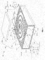
- Fig. 1 shows a simplified solar power harvesting system 300 of the present invention including a sunlight concentrating system 310, a TPV converter 200 including a spectrally-selective metamaterial emitter 100 and an associated PV cell 210, and a thermal power system 320 that combine to generate electrical energy E E-TOTAL with efficiencies that are much higher than is possible using conventional approaches.
- Sunlight concentrating system 310 utilizes one or more optical systems detailed below to provide concentrated sunlight (solar energy) E S to TPV converter 200.
- TPV converter 200 utilizes spectrally-selective metamaterial emitter 100 and associated PV cell 210 to convert solar energy E S into primary electrical energy E E1 with an efficiency that is significantly higher than that achieved by conventional TPV conversion approaches, and under certain operating conditions detailed below can reach 25% or higher.
- Thermal power system 320 enhances overall system efficiency by converting residual thermal energy E W (i.e., unconverted solar energy in the form of "waste" heat) into secondary electrical energy E E2 .
- solar power harvesting system 300 generates total electrical energy E E-TOTAL (i.e., the combination of primary electrical energy E E1 and secondary electrical energy E E2 ) with an efficiency of 42% or higher.
- sunlight concentrating system 310 utilizes one or more optical elements 311 to generate concentrated sunlight (solar energy) E S such that TPV converter 200 receives concentrated sunlight (solar energy) E S with an intensity greater than one-hundred (100) suns.
- optical elements 311 are depicted in Fig. 1 by lenses that focus and redirect sunlight beams SL onto TPV converter 200.
- sunlight concentrating system 310 is a ground-based heliostat including flat mirrors (optical elements) that are controlled using know techniques to track the sun's position such that reflected sunlight is directed toward TPV converter 200.
- optical elements 311 may include other flat mirror arrangements or curved mirrors to generate concentrated E S .
- metamaterial emitter 100 includes a box-like enclosure 110 on which is formed at least one bull's eye structure 120 that generates a radiant energy beam E R in the manner described below, and associated PV cell 210 is fixedly disposed adjacent to metamaterial emitter 100 such that it receives radiant energy beam E R .
- Box-like enclosure 110 includes a peripheral wall 111 defining (surrounding) an interior cavity 114 having an inlet opening 115, and is fixedly disposed relative to sunlight concentrating system 310 such that, during operation, concentrated sunlight E S is directed through inlet opening 115 and is thus supplied into interior cavity 114.
- Peripheral wall 111 includes an upper (first) peripheral wall portion 111-1 and a lower (second) peripheral wall portion 111-2 that are connected by respective side wall portions 111-3 and 111-4 such that peripheral wall portions 111-1 and 111-2 are disposed in an opposing spaced-apart (e.g., parallel) relationship, whereby a substantially rectangular interior cavity 114 is defined between wall portions 111-1 and 111-2.
- Peripheral wall portions 111-1 and 111-2 respectively include inward-facing surface portions 112-1 and 112-2 that face interior cavity 114C, and outward-facing surfaces 113-1 and 113-2 that face away from interior cavity 114 (i.e., upward and downward, respectively, from box-like enclosure 110).
- Peripheral wall portions 111-1 and 111-2 also extend between an inlet end 110-1 and an outlet end 110-2 of box-like enclosure 110, with inlet opening 115 being defined between respective front end portions 111-1F and 111-2F of peripheral wall portions 111-1 and 111-2, and an outlet opening 116 being defined between respective rear end portions 111-1R and 111-2F of peripheral wall portions 111C-1 and 111C-2.
- upper wall portion 111-1 is a planar, solid (plate-like) substrate formed such that lower (first) surface 112-1 and opposing upper (second) surface 113-1 are parallel planar surfaces.
- base substrate 111 is preferably entirely constructed from metal, and more preferably is entirely constructed using one or more refractory metals (e.g., Rhenium, Tantalum, or Tungsten), or a refractory metal alloy (e.g., Rhenium alloy).
- base substrate 111-1 has a thickness T on the order of more than a wavelength of emitted radiant energy E R (described below), but may have any arbitrary thickness outside of this constraint.
- bull's eye structure 120 includes concentric circular ridge structures 121-1, 121-2 and 121-3 that are integrally formed on upper surface 113-1 of upper wall portion (base substrate) 111-1 and respectively separated by intervening circular grooves 122-1, 122-2 and 122-3 that extend into (but not through) upper wall portion 111-1.
- circular ridge structures 121-1, 121-2 and 121-3 are either formed from the same material as upper wall portion 111-1 (e.g., by utilizing a subtractive process such as etching) or formed by an additive process such as sputtering that effectively melds (fuses) the added material to the base substrate material).
- Concentric ridge structures 121-1, 121-2 and 121-3 are formed such that each adjacent pair of ridge structures is separated by a fixed grating period (pitch distance) A.
- ridge structures 121-1 and 121-2 are separated by circular groove 122-1 such that the distance between an outside edge of ridge structure 121-1 and and outside edge of ridge structure 121-2 is equal to the grating period A.
- ridge structures 121-2 and 121-3 are separated by circular groove 122-2 such that the distance between an outside edge of ridge structure 121-2 and and outside edge of ridge structure 121-3 is equal to the same grating period ⁇ as that separating ridge structures 121-1 and 121-2.
- bull's eye structure 120 is configured such that, when solar energy E S is sufficient to heat box-like enclosure 110 to a temperature above 1000°K, radiant energy E R is emitted from upper surface 113-1 having a peak emission wavelength ⁇ peak that is roughly equal to (i.e., within 25% of) fixed grating period ⁇ .
- bull's eye structure 120 is configured such that emitted radiant energy beam E R is highly directional (i.e., 90% of the emitted radiant energy is within 0.5° of perpendicular (angle ⁇ ) to the planar outward-facing surface 113), narrow band (i.e., the full-width at half maximum of the emitted radiant energy is within 10% of peak emission wavelength ⁇ peak ), and peak emission wavelength ⁇ peak that is roughly equal to the fixed grating period ⁇ separating each adjacent pair of concentric circular ridge structures (i.e., the peak emission wavelength is within 25% of the grating period ⁇ ).
- metamaterial emitter 100 is selectively “tunable” (adjustable) by way of adjusting the fixed grating period ⁇ separating the concentric circular ridge structures 121-1 to 121-3.
- a relationship between the specific geometric dimensions associated with bull's eye structure 120 and the characteristics of emitted radiant energy beam E R are explained in additional detail in co-owned and co-pending U.S. Patent Application Serial Number 14/180,333 , entitled “SPECTRALLY-SELECTIVE METAMATERIAL EMITTER” [Atty Docket No. 20131311US01 (XCP-186-1)], which is incorporated herein by reference in its entirety.
- PV cell 210 is fixedly disposed adjacent to metamaterial emitter 100 such that radiant energy beam E R is directed onto PV cell 210, whereby PV cell 210 converts radiant energy beam E R into primary electrical energy E E1 using known photovoltaic techniques.
- bull's eye structure 120 is configured to generate radiant energy beam E R with an emission wavelength that is matched to the optimal conversion spectrum of PV cell 120.
- bull's eye structure 120 can include grating periods of almost any size
- ridge structures 121-1 to 121-3 typically have a grating period ⁇ in the range of 10 nanometers and 5.0 microns, which corresponds with the absorption curves of most commercially available PV cells (i.e., in the range of 0.5 microns to 3 microns).
- emitter 100 is produced with a grating period ⁇ in the range of 0.5 microns and 3.0 microns.
- PV cell 120 converts "in-band” photons (i.e., photons having energies within the specific optimal conversion spectrum of PV cell 120) at a higher efficiency than "out-of-band” photons (i.e., photons having energies outside the optimal conversion spectrum).
- bull's eye structure 120 is configured to "match" the EQE curve of PV cell 120 by forming bull's eye structure 120 with at least one fixed grating period A that is roughly equal to the wavelength of an "in-band" photon that is within the optimal absorption spectrum of PV cell 120.
- TPV converter 200 Additional details regarding TPV converter 200 are described in co-owned and co-pending U.S. Patent Application Serial Number xx/xxx,xxx, entitled “Metamaterial Enhanced Thermophotovoltaic Converter” [Atty Docket No. 20131311US02 (XCP-186-2)], which is incorporated herein by reference in its entirety.
- thermal power system 320 is positioned to receive unconverted thermal energy ("waste" heat energy) E W passed from the interior cavity 114 of the box-like enclosure 110 through outlet opening 116, and includes suitable mechanisms that convert thermal energy E W into secondary electric power E E2 .
- thermal power system 320 utilizes a heat exchanger that converts thermal energy E W to steam, and a generator that converts the steam into secondary electric power E E2 according to known techniques.
- thermal power system 320 is implemented using a high efficiency thermal power system (e.g., using a molten salt loop receiver). By combining TPV converter 200 with a suitable high efficiency thermal power system 320, the overall efficiency of solar power harvesting system 300 reaches 42% or higher.
- the performance of TPV converter 200 is enhanced using one or more features presented in the specific embodiments described below with reference to Figs. 2 to 5 .
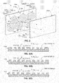
- Fig. 2 is a simplified perspective view showing a partial TPV converter 200A including a metamaterial emitter 100A having multiple bull's eye structures 120A-11 to 120A-13 and 120A-21 to 120A-23 that are formed on a "target-facing" surface 113A of a base substrate 111A in a manner similar to that described above.
- Figs. 3(A) to 3(C) are cross-sectional views taken along section lines 3A-3A, 3B-3B, and 3C-3C of Fig. 2 .
- Metamaterial emitter 100A is characterized in that it utilizes multiple bull's eye structures arranged in sets of three, where each bull's eye structure of each set has a different fixed grating period to effectively broaden a total radiant energy beam E R-TOTAL emitted by the metamaterial emitter 100A.
- the multiple bull's eye structures are arranged in two sets 120A-1 and 120A-2, where each set includes three bull's eye structures (i.e., set 120A-1 includes bull's eye structures 120A-11 to 120A-13, and set 120A-2 includes bull's eye structures 120A-21 to 120A-23).
- Each set 120A-1 and 120A-2 includes one bull's eye structure having grating period ⁇ 1, one bull's eye structure having grating period ⁇ 2, and one bull's eye structure having grating period ⁇ 3.
- set 120A-1 includes structure 120A-11 having concentric circular ridge structures spaced at a fixed grating period ⁇ 1 (e.g., the distance between adjacent structures 121A-111 and 121A-112 is equal to grating period ⁇ 1).
- Fig. 3(A) also represents bull's eye structure 210A-22 of set 120A-2, which includes ridge structures having fixed grating period ⁇ 1 formed in the same manner depicted by adjacent structures 121A-111 and 121A-112.
- Fig. 3(B) shows that both structure 120A-12 of set 120A-1 and structure 210A-22 of set 120A-2 have grating period ⁇ 2 (e.g., as depicted by adjacent structures 121A-121 and 121A-122, which are separated by grating period ⁇ 2)
- Fig. 3(C) shows that both structure 120A-13 of set 120A-1 and structure 210A-23 of set 120A-2 have grating period ⁇ 3 (e.g., as depicted by adjacent structures 121A-131 and 121A-132, which are separated by grating period ⁇ 3).
- metamaterial emitter 100A with three different grating periods is that this approach can be used to selectively broaden the overall spectrum of the total radiant energy beam E R-TOTAL emitted by metamaterial emitter 100A to associated PV cell 210A. That is, because the radiant energy generated by a particular bull's eye structure is related to its fixed grating period, a broadened the total radiant energy beam E R-TOTAL is generated by emitter 100A (shown in Fig. 2 ) by utilizing three different grating periods ⁇ l, ⁇ 2 and ⁇ 3. For example, assume fixed grating period ⁇ 3 is larger than fixed grating period ⁇ 2, and fixed grating period ⁇ 2 is larger than fixed grating period ⁇ 1. As indicated in Figs.
- these different grating periods generate component radiant energy beams to having different peak emission wavelengths. That is, because fixed grating period ⁇ 3 is greater than fixed grating period ⁇ 2, component radiant energy beams E R3 emitted from bull's eye structures 120-13 and 120-23 have a peak emission wavelength ⁇ peak3 that is greater than a peak emission wavelength ⁇ peak2 of radiant energy E R2 generated by bull's eye structures 120-12 and 120-22. Similarly, the peak emission wavelength ⁇ peak2 of radiant energy beam E R2 is greater than a peak emission wavelength ⁇ peak1 of radiant energy E R1 generated by bull's eye structures 120-11 and 120-21). Referring again to Fig.
- the total radiant energy beam E R-TOTAL is a combination of component radiant energy beams E R1 , E R2 and E R3 , and the effect of combining the adjacent narrowband spectra of component beams E R1 , E R2 and E R3 is to broaden the overall spectrum of total radiant energy beam E R-TOTAL .
- This approach can be used, for example, to provide more in-band photons to associated PV cell 210A, and consequently to increase the output power density of TPV converter 200A.
- a metamaterial emitter may include only two grating periods to facilitate the emission of a relatively narrow emission spectrum, or a spectrum having two separated "peak" emission wavelengths.
- the use of a large number of grating periods facilitates the emission of a relatively broad emission spectrum.
- Fig. 4 is a perspective view showing a TPV converter 200B having a metamaterial emitter 100B and a PV cell 210B, where metamaterial emitter 100B includes multiple bull's eye structures formed on a "target-facing" surface 113B of a base substrate 111B in a manner similar to that described above.
- Metamaterial emitter 100B differs from the previous embodiments in that the multiple bull's eye structures are formed in a "multiplexed" (overlapping) pattern (i.e., such that at least some of the circular ridge structures of one bull's eye structure intersect at least some of the circular ridge structures of at least one adjacent bull's eye structure). For example, referring to the upper left corner of Fig.
- bull's eye structure 120B-11 includes a first group of concentric circular ridge structures 121B-11
- adjacent bull's eye structure 120B-12 includes a second group of concentric circular ridge structures 121-12.
- Bull's eye structures 120B-11 and 120B-12 form a multiplexed pattern in that at least some of circular ridge structures 121B-11 of bull's eye structure 120B-11 intersect (overlap) at least some of circular ridge structures 121B-12 of bull's eye structure 120B-12.
- This multiplex pattern serves to concentrate radiant energy E R-TOTAL emitted by metamaterial emitter 100B, which can be used, for example, to provide more in-band photons to PV cell 210B, and consequently to increase the output power density of TPV converter 200B.
- metamaterial emitter 100B is also fabricated to employ the multiple-grating-period approach described above with reference to Fig. 2 (i.e., such that at least one bull's eye structure has a fixed grating period that is different (e.g., larger) than the fixed grating period of another bull's eye structure).
- the various multiplexed bull's eye structures of metamaterial emitter 100B are shown as being arranged in three sets: a first set 120B-1 including bull's eye structures 120B-11, 120B-12 and 120B-13, a second set 120B-2 including bull's eye structures 120B-21, 120B-22 and 120B-23, and a third set 120B-3 including bull's eye structures 120B-31, 120B-32 and 120B-33.
- Each set includes one bull's eye structure having a common first grating period (i.e., bull's eye structures 120B-11, 120B-21 and 120B-31 are fabricated using the same grating period in the manner described above with reference to Fig.
- one bull's eye structure having a second grating period i.e., bull's eye structures 120B-12, 120B-22 and 120B-32 are fabricated in the manner described above with reference to Fig. 3(B)
- one bull's eye structure having a third grating period i.e., bull's eye structures 120B-13, 120B-23 and 120B-33 are fabricated in the manner described above with reference to Fig. 3(B) ).
- metamaterial emitter 100B generates total radiant energy E R-TOTAL that both concentrates and combines adjacent narrowband spectra to produce a high energy emission with a broader overall spectrum that maximizes the number of in-band photons supplied to PV cell 210B, thereby maximizing the output power density of PV cell 210B.
- Fig. 5 is a perspective view showing a TPV converter 200C including a metamaterial emitter 100C and two PV cells 210C-1 and 210C-2.
- the "base substrate" of TPV converter 200C is formed as part of a box-like enclosure 110C that facilitates achieving optimal high operating temperatures (i.e., 1000°K to 1500°K).
- Box-like enclosure 110C includes a peripheral wall 111C having an upper (first) peripheral wall portion 111C-1 and a lower (second) peripheral wall portion 111C-2 that are connected by respective side wall portions in an opposing spaced-apart (e.g., parallel) relationship such that a substantially rectangular interior cavity 114C is defined between wall portions 111C-1 and 111C-2.
- Peripheral wall portions 111C-1 and 111C-2 respectively include inward-facing surface portions 112C-1 and 112C-2 that face an interior cavity 114C, and outward-facing surfaces 113C-1 and 113C-2 that face away from interior cavity 114C (i.e., upward and downward, respectively, from box-like enclosure 110C).
- Peripheral wall portions 111C-1 and 111C-2 extend between an inlet end 110C-1 and an outlet end 110C-2 of box-like enclosure 110C such that an inlet opening 115C is defined between respective front end portions 111C-1R and 111C-2R of peripheral wall portions 111C-1 and 111C-2, and an outlet opening 116C is defined between respective rear end portions 111C-1F and 111C-2R of peripheral wall portions 111C-1 and 111C-2.
- “source” heat energy E S is supplied into the interior cavity 114C through inlet opening 115C, and "waste" heat energy is evacuated through outlet opening 116C.
- Metamaterial emitter 100C includes two bull's eye structures 120C-1 and 120C-2 formed in the manner described above that are disposed on outward facing surfaces 113C-1 and 113C-2, respectively.
- bull's eye structure 120C-1 is disposed on upward-facing surface 113C-1 of upper peripheral wall portion 111C-1 and includes concentric circular ridge structures 121C-1 separated by intervening circular grooves 122C-1 and separated by a fixed grating period ⁇ 1
- bull's eye structure 120C-2 is disposed on downward-facing surface 113C-2 of lower peripheral wall portion 111C-2 and includes concentric circular ridge structures 121C-2 separated by intervening circular grooves 122C-2 and separated by a fixed grating period ⁇ 2.
- PV cells 210C-1 and 210C-2 are essentially identical (i.e., having the same spectral response), so fixed grating period ⁇ 2 is the same as fixed grating period ⁇ 1.
- PV cells 210C-1 and 210C-2 have different spectral responses, so fixed grating period ⁇ 2 is different from (e.g., larger or smaller than) fixed grating period ⁇ 1.
- the box-like enclosure arrangement of metamaterial emitter 100C provides optimal energy beam generation because flat/planar peripheral wall portions 111C-1 and 111C-2 facilitate cost-effective fabrication of the bull's eye structures thereon (e.g., using existing photolithographic fabrication techniques), and because rectangular-shaped interior cavity 114C facilitates the efficient transfer of heat energy over the "base substrate" formed by peripheral wall portions 111C-1 and 111C-2.
- the rectangular box-like arrangement facilitates the transfer of heat energy in the form of concentrated sunlight that reflects between the opposing upper and lower interior surfaces 112C-1 and 112C-2, thereby heating peripheral wall portions 111C-1 and 111C-2, and allowing associated waste heat to be removed from interior cavity 114C through outlet opening 116C.
- this arrangement allows TPV converter 200C to provide increased electricity generation over a single PV cell approach.
- the gist of this approach is further expanded to employ additional bull's eye structures and additional PV cells (e.g., disposed along the sides of box-like enclosure 110C, or along multiple surfaces of a non-rectangular box-shaped enclosure) to potentially further increase electricity generation.
- box-like enclosure 110C is constructed as an all-metal structure (e.g., constructed from a single metal block or by welding or otherwise securing four metal plates together).
- the all-metal structure facilitates achieving the required high operating temperatures (i.e., 1000 to 1500°K) over a suitable operating lifetime of metamaterial emitter 100C.
- the all-metal box-like enclosure 110C is formed entirely using one or more refractory metals (e.g., Rhenium, Tantalum or Tungsten) or refractory metal alloys to further enhance the enclosure's operational lifetime.
- Fig. 6 is a simplified diagram showing a solar tower power harvesting system 300D utilizing both a TPV converter 200D disposed on a tower 305D, a heliostat-type solar concentrating system 310D, and a conventional steam production-type thermal power system 320D.
- TPV converter 200D which is described in additional detail below, includes a metamaterial emitter 100D comprising a box-like enclosure 110D that is mounted to the top of tower 305D, and includes corresponding bull's eye structure arrays 120D-1 and 120D-2 and corresponding PV cells 210D-1 and 210D-2 that function as described herein to generate primary electrical energy E E1 .
- Heliostat-type solar concentrating system 310D includes an array of mirrors 311D (only three are shown for illustrative purposes) disposed at ground level in a designated (e.g., 100 meter by 100 meter) area next to tower 305D, and a control system (not shown) that controls mirrors 311D to track the sun's movement during daylight hours using known techniques in order to reflected sunlight through an inlet opening 115D of box-like enclosure 110D.
- a control system not shown
- Thermal power system 320D includes a primary heat exchange unit 321D that is connected to an associated receiver 323D by way of a first conduit 322D, a steam generating (secondary heat exchange) unit 324D connected to the receiver/pump 323D, a turbine 326D that is coupled by way of conduit 325D to receive steam from steam generating unit 324D, a steam condenser 327D, and a generator 328D driven by turbine 236D to generate secondary electrical energy E E2 .
- a heat transfer fluid is circulated by way of conduits 3322D to be heated in primary heat exchange unit 321D by waste heat exiting box-like enclosure 110D.
- the heated fluid is optionally stored in receiver 323D, and circulated through steam generating unit 324D to generate steam at a suitable temperature (e.g., 550°C).
- the steam is then passed by way of conduits 325D to drive turbine 326D, which in turn drives generator 328D.
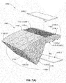
- Figs. 7(A) and 7(B) are perspective and cross-sectional side views showing metamaterial emitter 100D of TPV converter 200D in additional detail.
- Metamaterial emitter 100D is similar to that described above with reference to Fig. 5 in that box-like enclosure 110D includes opposing upper (first) and lower (second) peripheral wall portions 111D-1 and 111D-2 that are connected by respective side wall portions in an opposing spaced-apart (e.g., parallel) relationship, and such that arrays 120D-1 and 120D-2 of bull's eye structures are respectively formed on outward-facing surfaces 113D-1 and 113D-2 of wall portions 111D-1 and 111D-2.
- Bull's eye structure arrays 120D-1 and 120D-2 are implemented using any of the various arrangements described above, but preferably include a multiplexed arrangement such as that shown in Fig. 4 to maximize the amount of energy transmitted in emitted radiant energy beams E R1 and E R2 .
- Metamaterial emitter 100D differs from previous embodiments in that it includes a compound parabolic trough 117D disposed at the inlet end of box-like enclosure 110D.
- the compound parabolic trough includes an upper (first) compound parabolic trough structure 117D-1 integrally connected to a front end portion 111D-1F of upper peripheral wall portion 111D-1, and a lower (second) compound parabolic trough structure 117D-2 integrally connected to a front end portion 111D-2F of lower peripheral wall portion 111D-2.
- the compound parabolic trough includes an upper (first) compound parabolic trough structure 117D-1 integrally connected to a front end portion 111D-1F of upper peripheral wall portion 111D-1, and a lower (second) compound parabolic trough structure 117D-2 integrally connected to a front end portion 111D-2F of lower peripheral wall portion 111D-2.
- compound parabolic trough structures 117D-1 and 117D-2 are operably shaped to channel concentrated sunlight E S through the inlet opening 115D into interior cavity 114D between peripheral wall portions 111D-1 and 111D-2 such that the sunlight reflects between the inside surfaces 112D-212 and 112D-222 of peripheral wall portions 111D-1 and 111D-2 in a manner that maximizes the transfer of heat energy to bull's eye structure arrays 120D-1 and 120D-2, which in turn maximizes the amount of radiant energy emitted in beams E R1 and E R2 respectively emitted from bull's eye structure arrays 120D-1 and 120D-2 to PV cells 210D-1 and 210D-2, respectively.
- Metamaterial emitter 100D also differs from previous embodiments in that it includes a funnel-shaped outlet 117D disposed at the outlet end of box-like enclosure 110D that serves to control the release of "waste" heat from interior cavity 114D.
- the funnel-shaped outlet includes an upper (first) funnel-shaped outlet structure 118D-1 integrally connected to a rear end portion 111D-1R of upper peripheral wall portion 111D-1, and a lower (second) funnel-shaped outlet structure 118D-2 integrally connected to a rear end portion 111D-2R of lower peripheral wall portion 111D-2.
- funnel-shaped outlet structures 118D-1 and 118D-2 are operably shaped to channel "waste" heat energy E W from interior cavity 114D through outlet opening 116D at a rate that optimizes energy transfer to bull's eye structure arrays 120D-1 and 120D-2.
- the entirety of all-metal box-like enclosure 110D is constructed using metal, and more preferably using a single refractory metal (e.g., Rhenium, a Rhenium alloy, Tantalum or Tungsten).
- a single refractory metal e.g., Rhenium, a Rhenium alloy, Tantalum or Tungsten.
- box-like enclosure 110D is maintained at a tilted angle ⁇ relative to ground level GL in order to facilitate transfer of solar energy into interior cavity 114D, and also to cause a naturally occurring convective air current that moves the unconverted thermal energy E W from the interior cavity 114D through outlet opening 116D to thermal power system 320D (not shown).
- box-like enclosure 110D is maintained such that outlet opening 116D and funnel-shaped outlet structures 118D-1 and 118D-2 are higher (i.e., further from ground level) than inlet opening 115D compound parabolic trough structures 117D-1 and 117D-2.
- Fig. 8 shows a portion of a solar power system 300D according to another specific embodiment.
- Solar power system 300D is similar to the previous embodiment in that it utilizes TPV converter 200D (i.e., metamaterial emitter 100D and matched PV cells 210D-1 and 210D-2, described above) to generate primary electrical energy.
- Solar power system 300D differs from the previous embodiment in that it includes a thermal power system 320E implemented using a molten salt loop system, such as that used by Sandia National Laboratories in Livermore, CA, USA, in which molten salt is pumped between a receiver 323D and a heat exchanger 321D by way of conduits 322D.
- Heat exchanger 321d is operably thermally coupled to metamaterial emitter 110D such that waste heat exiting by way of outlet opening 116D is transferred to the circulating molten salt.
- the molten salt is an excellent energy storage media, which can then be collected in large storage vessels for later use to generate secondary electrical energy with high efficiency.
- the solar tower power harvesting system shown in Fig. 6 may be modified to utilize bull's eye structure arrays according to any of the approaches described with reference to Figs. 2 to 5 .
Landscapes
- Physics & Mathematics (AREA)
- Engineering & Computer Science (AREA)
- General Physics & Mathematics (AREA)
- Chemical & Material Sciences (AREA)
- Nanotechnology (AREA)
- Condensed Matter Physics & Semiconductors (AREA)
- Manufacturing & Machinery (AREA)
- Crystallography & Structural Chemistry (AREA)
- Optics & Photonics (AREA)
- Photovoltaic Devices (AREA)
Abstract
Description
- This invention relates to apparatus and methods for converting solar energy to electric power.
- Thermophotovoltaic (TPV) energy conversion involves the conversion of heat to electricity, and has been identified as a promising technology since the 1960's. A basic TPV system includes a thermal emitter and a photovoltaic diode receiver. The thermal emitter is typically a piece of solid material or a specially engineered structure that generates thermal emission when heated to a high temperature (i.e., typically in a range from about 1200°K to about 1500°K). Thermal emission is the spontaneous radiation (emission) of photons due to thermal motion of charges in the thermal emitter material. For normal TPV system operating temperatures, the radiated photons are mostly at near infrared and infrared frequencies. The photovoltaic diode receiver includes a photovoltaic (PV) cell positioned to absorb some of these radiated photons, and is constructed to convert the absorbed photons into free charge carriers (i.e., electricity) in the manner typically associated with conventional solar cells. In effect, a solar energy system is a type of TPV energy conversion system where the sun acts as the thermal emitter. However, the present invention is directed to "earth-bound" TPV energy conversion systems in which the thermal emitter is solid structure that is heated from an external source (e.g., by concentrated sunlight or other heat generator).
- Although TPV energy conversion is promising in theory, practical conventional TPV systems have achieved far lower efficiencies than theoretically predicted. A TPV system can be modeled as a heat engine in which the hot body (i.e., the heated thermal emitter) is described as a blackbody radiation source having a black body temperature TBB, and the relatively cold PV receiver has a temperature T PV, whereby the theoretical thermodynamic efficiency limit is given by the Carnot cycle η Carnot = (T BB-T PV) /T BB. For a thermal emitter temperature T BB equal to 1500°K and a PV receiver temperature T PV equal to 300°K, a theoretical efficiency η Carnot equals 0.8 (80%), which exceeds the Shockley-Queisser limit (i.e., the maximum theoretical efficiency of a solar cell using a p-n junction to collect power). In reality, however, the efficiencies of conventional TPV systems are reported to be below 10%. This is believed to stem from a mismatch between the spectrum of the thermal emitter and the PV cell.
- One reason for the lower realized efficiencies of conventional TPV systems is related to carrier thermalization at high temperatures caused by a mismatch between the emitted photons and the PV cells. Thermal radiation from the thermal emitter (hot body) of a TPV system has a spectral power density given by Planck's law, and the peak wavelength λmax is given by Wien's law (λ max ∼ (2898/T BB) µm). For high-temperature emitters (1100°K ≤T BB ≤1500°K), the peak wavelength λ max is in the range of 1.9 to 2.6 µm, which requires the TPV system to utilize PV cells having low bandgap semiconductors (i.e., around 0.5-0.8 eV). Using such low bandgap PV cells requires the use of emitter materials having bandgaps closer to 0.5 eV (∼2.5 µm) in order to obtain a larger fraction of in-band photons at reasonable emitter temperatures (i.e., 1100-1500°K). If emitter materials having bandgaps below 0.5 eV are used, the PV cell performance suffers from high carrier thermalization at the elevated temperatures required in TPV systems.
- What is needed is a solar power harvesting system that converts solar energy to electrical energy with an efficiency of 42% or higher.
- The present invention is directed to a high efficiency solar power system that utilizes a sunlight concentrating system (e.g., a heliostat) to provide solar energy (i.e., concentrated sunlight) to a novel solar thermophotovoltaic (TPV) converter and a thermal storage system. The novel solar TPV converter utilizes a spectrally-selective metamaterial emitter that matches the optimal conversion spectrum of an associated low-bandgap photovoltaic (PV) cell to convert the solar energy into primary electric energy with an efficiency of greater than 25% at elevated operating temperatures (i.e., greater than 1400°K). The thermal storage system is operably coupled to the metamaterial emitter to capture (and optionally store) unused thermal energy from (i.e., solar energy not converted by) the TPV converter, and to convert the unused thermal energy into secondary electric energy. By combining the novel solar TPV converter and the thermal storage system, the present invention provides a solar power system capable of generating total system electrical power at an efficiency of 42% or greater, which represents a dramatic improvement over existing conventional solar power systems.
- According to an aspect of the present invention, the spectrally-selective metamaterial emitter includes a box-like enclosure having an interior cavity surrounded by a peripheral wall, and at least one novel bull's eye structure disposed on outward-facing surfaces of the peripheral wall. The box-like enclosure is fixedly disposed and operably positioned relative to the sunlight concentrating system (e.g., on a tower above a ground-based heliostat) such that the concentrated sunlight is directed through an inlet opening into the interior cavity, whereby the box-like enclosure is heated to an suitable operating temperature (i.e., above 1000°K). The novel bull's eye structures includes concentric circular ridge structures disposed in an associated fixed grating period that emit a highly directional, narrow spectral width radiant energy beam having a peak emission wavelength roughly equal to the fixed grating period. That is, the metamaterial thermal emitter effectively functions as a narrowband filter element with a spectral response that is selectively "tunable" by way of adjusting the fixed grating period. The PV cells are positioned to receive the radiant energy beam, and are "matched" to the metamaterial emitter in that their optimal radiation absorption/conversion wavelengths (absorption curves) correspond to (i.e., equal or overlap) the peak emission wavelengths of the radiant energy beam. By optimally "matching" the spectrum of a PV cell using the spectrally-selective metamaterial emitter, the solar power system of the present invention is able to generate primary electric energy at much higher efficiencies than is possible using conventional systems.
- According to an embodiment of the present invention, the sunlight concentrating system includes multiple optical elements (e.g., lenses and/or mirrors) that are operably disposed to generate concentrated sunlight with a sufficient intensity (e.g., greater than 100 suns) at the inlet opening of the box-like enclosure to heat the metamaterial emitter to an optimal operating temperature (i.e., between 1000°K and 1500°K) during daylight hours. In addition, the entire metamaterial thermal emitter (i.e., both the box-like enclosure and the bull's eye" structures) is implemented as an all-metal structure (i.e., entirely formed using one or more metals or metal alloys). This all-metal construction is critical for withstanding the high optimal operating temperatures (i.e., 1000°K to 1500°K) without delamination (which can occur when one or more dielectric are used), and because metallic surfaces support surface plasmons or spoof surface plasmons that are required to facilitate the efficient emission of the highly directional, narrow band radiant energy and having the desired peak emission wavelength. In a specific embodiment, both the box-like enclosure and the bull's eye" structure are entirely formed using one or more refractory metals (e.g., Rhenium, Tantalum or Tungsten) because these metals are able to withstand the higher operating temperatures (i.e., approaching 1500°K) without melting or deforming. In a presently preferred embodiment, both the box-like enclosure and the bull's eye" structure are entirely formed using Rhenium or a Rhenium alloy because the ability of this metal/alloys to withstand high temperatures is well known from their use in high-performance jet and rocket engines.
- Because the in-band photons associated with most PV cells are in the range of 0.5 microns to 3 microns, this means that the bull's eye structures are fabricated with fixed grating periods in the range of 10 nanometers and 5 microns. In a presently preferred embodiment, a metamaterial emitter is produced with bull's eye structures having a grating period in the range of 0.5 to 3.0 microns (e.g., 1.5 microns) in order to match the specific absorption curves of a selected low-bandgap (e.g., GaSb) PV cell having a cell-specific optimal wavelength range of 1.0 to 2.0 microns.
- According to a specific embodiment of the present invention, the metamaterial thermal emitter is configured to include multiple bull's eye structures disposed in an array of the peripheral wall of the box-like enclosure in order to produce a broad spectral bandwidth radiant energy beam thus increasing the number of in-band photons that are efficiently converted by the associated PV cell into electricity. In a specific embodiment, the bull's eye structures are disposed in sets of two or more, with each bull's eye structure of each set having a corresponding fixed grating period between adjacent concentric circular ridges that is different from the fixed grating periods of the other bull's eye structures of that set. In an exemplary embodiment, the associated PV cell is a low-bandgap PV cell having an optimal wavelength range of approximately 1.5 microns, and each set includes three bull's eye structures respectively having concentric circular ridges that are formed with corresponding fixed grating periods that are equal to 1.3 microns, 1.5 microns and 1.7 microns, respectively. The different bull's eye structures of each set produce a mix of photons having the various wavelengths determined by the different grating periods, thereby producing a broadened emission spectrum that overlaps the associated PV cell's optimal wavelength range, which increases the number of in-band photons for conversion by the associated PV cell.
- In another specific embodiment, the metamaterial thermal emitter of a TPV converter is configured to include an array of bull's eye structures arranged in a multiplexed (overlapping) pattern (i.e., such that at least some of the concentric circular ridge structures of each bull's eye structure intersect at least some of the concentric circular ridge structures of an adjacent bull's eye structure, thereby concentrating the emitted radiant energy to increase the PV cell's output power density. Further, by disposing the bull's eye structures in sets having different fixed grating periods, as described above, the metamaterial thermal emitter both concentrates and combines adjacent narrowband spectra to produce a high energy emission with a broader overall spectrum that can be used, for example, to maximize the number of in-band photons converted by a target PV cell, thereby maximizing the PV cell's output power density.
- According to an exemplary embodiment of the present invention, the metamaterial emitter of a TPV converter includes a box-like enclosure formed by a peripheral wall, with one or more bull's eye structures disposed as described above on at least two outward facing surfaces of the peripheral wall (i.e., such that at least two radiant energy beams are emitted in at least two (e.g., upward and downward) directions from the metamaterial emitter), and the TPV converter further includes at least two PV cells positioned to receive the at least two radiant energy beams. The peripheral wall of the emitter's box-like enclosure surrounds a substantially rectangular interior cavity and includes an inlet opening through which heat energy (e.g., concentrated sunlight) is supplied into the cavity during operation, and an outlet opening through which waste heat is allowed to exit the cavity. Each bull's eye structure is configured to generate a radiant energy beam that is matched to the associated PV cell positioned to receive the radiant energy beam. This arrangement provides optimal energy beam generation because the flat/planar wall surfaces facilitate cost-effective fabrication of the bull's eye structures (i.e., using existing photolithographic fabrication techniques), and the rectangular-shaped interior cavity defined between the two opposing flat peripheral wall portions facilitates efficient transfer of heat energy (e.g., by allowing concentrated sunlight to reflect between the opposing interior surfaces as it propagates along the interior cavity). In one embodiment, the box-like enclosure is formed entirely from refractory metals (e.g., Rhenium, Tantalum or Tungsten) to facilitate the required high operating temperatures (i.e., 1000 to 1500°K) and to enhance the enclosure's operational lifetime.
- According to another embodiment of the present invention, a solar-tower power harvesting system is implemented by mounting a metamaterial emitter on a tower, and utilizes a heliostat (sunlight concentrating system) including multiple mirrors to reflect sunlight beams onto the raised metamaterial emitter. The heliostat includes an array of mirrors that are disposed at ground level and are controlled (e.g., rotated and tilted) in a manner that tracks the sun's azimuth and elevation angles such that sunlight is reflected onto the raised metamaterial emitter at all times during daylight hours. In yet another specific embodiment, the box-like enclosure includes compound parabolic trough structures respectively integrally connected to front end portions of the opposing peripheral wall portions, wherein the compound parabolic trough structures are configured to channel solar energy into the interior cavity in a manner that maximizes the transfer of heat energy to the peripheral wall portions, which in turn maximizes the amount of radiant energy emitted in the radiant energy beam to the associated PV cells. In addition, a funnel-shaped outlet opening is formed by corresponding metal structures respectively integrally connected to the rear end portions of the peripheral wall portions. In a specific embodiment, the box-like enclosure is maintained at a tilted angle (i.e., such that the outlet opening is higher than the inlet opening) in order to facilitate transfer of solar energy into the interior cavity, and also to cause a naturally occurring convective air current that moves the unconverted thermal energy from the interior cavity through the funnel-shaped outlet opening to the thermal power system. In another specific embodiment, a molten salt-based thermal storage system is operably coupled to the funnel-shaped outlet of the box-like enclosure that includes a receiver for storing the unconverted thermal energy passed out of the interior cavity, and corresponding mechanisms (e.g., a boiler, a turbine, a generator, and a steam condenser) are connected to the receiver and serve to convert the stored thermal energy into said secondary electric power. Various additional features discussed above are utilized in the solar-tower power harvesting system to further maximize efficiency (e.g., utilizing multiplexed bull's eye structures, utilizing an all-refractor-metal box-like structure, and matching the fixed grating periods of the bull's eye structures to the optimal conversion frequency of the associated PV cells).
- These and other features, aspects and advantages of the present invention will become better understood with regard to the following description, appended claims, and accompanying drawings, where:
-
Fig. 1 is a perspective view showing a simplified solar power harvesting system according to an embodiment of the present invention; -
Fig. 2 is a perspective view showing a TPV converter utilized by a solar power harvesting system according to a second embodiment of the present invention; -
Figs. 3(A), 3(B) and 3(C) are cross-sectional side views taken alongsection lines 3A-3A, 3B-3B and 3C-3C, respectively, ofFig. 2 showing bull's eye structures with different fixed grating periods; -
Fig. 4 is a perspective view showing a TPV converter utilized by a solar power harvesting system according to a third embodiment of the present invention; -
Fig. 5 is a perspective view showing a TPV converter utilized by a solar power harvesting system according to a fourth embodiment of the present invention; -
Fig. 6 is a diagram showing a solar tower power harvesting system according to a fifth embodiment of the present invention; -
Figs. 7(A) and7(B) are perspective and cross-sectional side views, respectively, showing a TPV converter utilized in the solar tower power harvesting system ofFig. 6 ; and -
Fig. 8 is a perspective view showing a partial solar power harvesting system according to a sixth embodiment of the present invention. - The present invention relates to an improved solar power harvesting system that utilizes a TPV converter. The following description is presented to enable one of ordinary skill in the art to make and use the invention as provided in the context of a particular application and its requirements. As used herein, directional terms such as "upper", "upward", "lower", "downward", "over", "under", "front" and "rear", are intended to provide relative positions for purposes of description, and are not intended to designate an absolute frame of reference. In addition, the phrases "integrally formed" and "integrally connected" are used herein to describe the connective relationship between two portions of a single fabricated or machined structure, and are distinguished from the terms "connected" or "coupled" (without the modifier "integrally"), which indicates two separate structures that are joined by way of, for example, adhesive, fastener, clip, or movable joint. Various modifications to the preferred embodiment will be apparent to those with skill in the art, and the general principles defined herein may be applied to other embodiments. Therefore, the present invention is not intended to be limited to the particular embodiments shown and described, but is to be accorded the widest scope consistent with the principles and novel features herein disclosed.
-
Fig. 1 shows a simplified solarpower harvesting system 300 of the present invention including asunlight concentrating system 310, aTPV converter 200 including a spectrally-selective metamaterial emitter 100 and an associatedPV cell 210, and athermal power system 320 that combine to generate electrical energy EE-TOTAL with efficiencies that are much higher than is possible using conventional approaches.Sunlight concentrating system 310 utilizes one or more optical systems detailed below to provide concentrated sunlight (solar energy) ES toTPV converter 200.TPV converter 200 utilizes spectrally-selective metamaterial emitter 100 and associatedPV cell 210 to convert solar energy ES into primary electrical energy EE1 with an efficiency that is significantly higher than that achieved by conventional TPV conversion approaches, and under certain operating conditions detailed below can reach 25% or higher.Thermal power system 320 enhances overall system efficiency by converting residual thermal energy EW (i.e., unconverted solar energy in the form of "waste" heat) into secondary electrical energy EE2. By combining the high efficiency ofTPV converter 200 with a high efficiencythermal power system 320, solarpower harvesting system 300 generates total electrical energy EE-TOTAL (i.e., the combination of primary electrical energy EE1 and secondary electrical energy EE2) with an efficiency of 42% or higher. - The various components of solar
power harvesting system 300 are now described in additional detail. - Referring to the lower left corner of
Fig. 1 ,sunlight concentrating system 310 utilizes one or moreoptical elements 311 to generate concentrated sunlight (solar energy) ES such thatTPV converter 200 receives concentrated sunlight (solar energy) ES with an intensity greater than one-hundred (100) suns. For simplicity,optical elements 311 are depicted inFig. 1 by lenses that focus and redirect sunlight beams SL ontoTPV converter 200. In a presently preferred embodiment,sunlight concentrating system 310 is a ground-based heliostat including flat mirrors (optical elements) that are controlled using know techniques to track the sun's position such that reflected sunlight is directed towardTPV converter 200. In other possible embodiments,optical elements 311 may include other flat mirror arrangements or curved mirrors to generate concentrated ES. - Referring to TPV converter 200 (located in the center of
Fig. 1 ),metamaterial emitter 100 includes a box-like enclosure 110 on which is formed at least one bull'seye structure 120 that generates a radiant energy beam ER in the manner described below, and associatedPV cell 210 is fixedly disposed adjacent tometamaterial emitter 100 such that it receives radiant energy beam ER. - Box-like enclosure 110 includes a
peripheral wall 111 defining (surrounding) aninterior cavity 114 having aninlet opening 115, and is fixedly disposed relative tosunlight concentrating system 310 such that, during operation, concentrated sunlight ES is directed through inlet opening 115 and is thus supplied intointerior cavity 114.Peripheral wall 111 includes an upper (first) peripheral wall portion 111-1 and a lower (second) peripheral wall portion 111-2 that are connected by respective side wall portions 111-3 and 111-4 such that peripheral wall portions 111-1 and 111-2 are disposed in an opposing spaced-apart (e.g., parallel) relationship, whereby a substantially rectangularinterior cavity 114 is defined between wall portions 111-1 and 111-2. Peripheral wall portions 111-1 and 111-2 respectively include inward-facing surface portions 112-1 and 112-2 that faceinterior cavity 114C, and outward-facing surfaces 113-1 and 113-2 that face away from interior cavity 114 (i.e., upward and downward, respectively, from box-like enclosure 110). Peripheral wall portions 111-1 and 111-2 also extend between an inlet end 110-1 and an outlet end 110-2 of box-like enclosure 110, with inlet opening 115 being defined between respective front end portions 111-1F and 111-2F of peripheral wall portions 111-1 and 111-2, and an outlet opening 116 being defined between respective rear end portions 111-1R and 111-2F ofperipheral wall portions 111C-1 and 111C-2. To facilitate the fabrication of bull'seye structure 120 using photolithography, upper wall portion 111-1 is a planar, solid (plate-like) substrate formed such that lower (first) surface 112-1 and opposing upper (second) surface 113-1 are parallel planar surfaces. In addition, for reasons set forth below,base substrate 111 is preferably entirely constructed from metal, and more preferably is entirely constructed using one or more refractory metals (e.g., Rhenium, Tantalum, or Tungsten), or a refractory metal alloy (e.g., Rhenium alloy). In an exemplary practical exemplary embodiment (e.g., when used as part of TPV system 200), base substrate 111-1 has a thickness T on the order of more than a wavelength of emitted radiant energy ER (described below), but may have any arbitrary thickness outside of this constraint. - Referring to the upper portion of box-like enclosure 110, bull's
eye structure 120 includes concentric circular ridge structures 121-1, 121-2 and 121-3 that are integrally formed on upper surface 113-1 of upper wall portion (base substrate) 111-1 and respectively separated by intervening circular grooves 122-1, 122-2 and 122-3 that extend into (but not through) upper wall portion 111-1. In particular, circular ridge structures 121-1, 121-2 and 121-3 are either formed from the same material as upper wall portion 111-1 (e.g., by utilizing a subtractive process such as etching) or formed by an additive process such as sputtering that effectively melds (fuses) the added material to the base substrate material). Concentric ridge structures 121-1, 121-2 and 121-3 are formed such that each adjacent pair of ridge structures is separated by a fixed grating period (pitch distance) A. For example, ridge structures 121-1 and 121-2 are separated by circular groove 122-1 such that the distance between an outside edge of ridge structure 121-1 and and outside edge of ridge structure 121-2 is equal to the grating period A.
Similarly, ridge structures 121-2 and 121-3 are separated by circular groove 122-2 such that the distance between an outside edge of ridge structure 121-2 and and outside edge of ridge structure 121-3 is equal to the same grating period Λ as that separating ridge structures 121-1 and 121-2. - According to an aspect of the present invention, bull's
eye structure 120 is configured such that, when solar energy ES is sufficient to heat box-like enclosure 110 to a temperature above 1000°K, radiant energy ER is emitted from upper surface 113-1 having a peak emission wavelength λpeak that is roughly equal to (i.e., within 25% of) fixed grating period Λ. According to another aspect of the present invention, bull'seye structure 120 is configured such that emitted radiant energy beam ER is highly directional (i.e., 90% of the emitted radiant energy is within 0.5° of perpendicular (angle θ) to the planar outward-facing surface 113), narrow band (i.e., the full-width at half maximum of the emitted radiant energy is within 10% of peak emission wavelength λpeak ), and peak emission wavelength λpeak that is roughly equal to the fixed grating period Λ separating each adjacent pair of concentric circular ridge structures (i.e., the peak emission wavelength is within 25% of the grating period Λ). Accordingly,metamaterial emitter 100 is selectively "tunable" (adjustable) by way of adjusting the fixed grating period Λ separating the concentric circular ridge structures 121-1 to 121-3. A relationship between the specific geometric dimensions associated with bull'seye structure 120 and the characteristics of emitted radiant energy beam ER are explained in additional detail in co-owned and co-pendingU.S. Patent Application Serial Number 14/180,333 , entitled "SPECTRALLY-SELECTIVE METAMATERIAL EMITTER" [Atty Docket No. 20131311US01 (XCP-186-1)], which is incorporated herein by reference in its entirety. - According to an aspect of the present invention,
PV cell 210 is fixedly disposed adjacent tometamaterial emitter 100 such that radiant energy beam ER is directed ontoPV cell 210, wherebyPV cell 210 converts radiant energy beam ER into primary electrical energy EE1 using known photovoltaic techniques. According to an embodiment of the present invention, bull'seye structure 120 is configured to generate radiant energy beam ER with an emission wavelength that is matched to the optimal conversion spectrum ofPV cell 120. That is, although bull'seye structure 120 can include grating periods of almost any size, ridge structures 121-1 to 121-3 typically have a grating period Λ in the range of 10 nanometers and 5.0 microns, which corresponds with the absorption curves of most commercially available PV cells (i.e., in the range of 0.5 microns to 3 microns). In a particularly preferred embodiment (e.g., whenPV cell 210 is a GaSb PV cell having an optimal wavelength range of said PV cell is 1.0 microns to 2.0 microns),emitter 100 is produced with a grating period Λ in the range of 0.5 microns and 3.0 microns. As is known in the art,PV cell 120 converts "in-band" photons (i.e., photons having energies within the specific optimal conversion spectrum of PV cell 120) at a higher efficiency than "out-of-band" photons (i.e., photons having energies outside the optimal conversion spectrum). To improve the efficiency ofTPV converter 200, bull'seye structure 120 is configured to "match" the EQE curve ofPV cell 120 by forming bull'seye structure 120 with at least one fixed grating period A that is roughly equal to the wavelength of an "in-band" photon that is within the optimal absorption spectrum ofPV cell 120. Accordingly, whenmetamaterial emitter 100 is heated to a temperature above 1000°K, bull'seye structure 120 generates radiant energy beam ER with a peak emission wavelength λpeak that is within the optimal conversion spectrum ofPV cell 120, whereby the spectrally-selective metamaterial emitter 100 is "matched" to the associatedPV cell 210 in the sense that a high percentage of the photons forming the radiant energy beam ER are absorbable/convertible byPV cell 120. Further, whenmetamaterial emitter 100 is heated to a temperature above 1400°K, the overall efficiency ofTPV converter 200 is increased to 25% or higher. - Additional details regarding
TPV converter 200 are described in co-owned and co-pending U.S. Patent Application Serial Number xx/xxx,xxx, entitled "Metamaterial Enhanced Thermophotovoltaic Converter" [Atty Docket No. 20131311US02 (XCP-186-2)], which is incorporated herein by reference in its entirety. - Referring to the right side of
Fig. 1 ,thermal power system 320 is positioned to receive unconverted thermal energy ("waste" heat energy) EW passed from theinterior cavity 114 of the box-like enclosure 110 through outlet opening 116, and includes suitable mechanisms that convert thermal energy EW into secondary electric power EE2. In a generalized exemplary embodiment,thermal power system 320 utilizes a heat exchanger that converts thermal energy EW to steam, and a generator that converts the steam into secondary electric power EE2 according to known techniques. In a preferred embodiment,thermal power system 320 is implemented using a high efficiency thermal power system (e.g., using a molten salt loop receiver). By combiningTPV converter 200 with a suitable high efficiencythermal power system 320, the overall efficiency of solarpower harvesting system 300 reaches 42% or higher. - According to alternative embodiments, the performance of
TPV converter 200 is enhanced using one or more features presented in the specific embodiments described below with reference toFigs. 2 to 5 . -
Fig. 2 is a simplified perspective view showing apartial TPV converter 200A including ametamaterial emitter 100A having multiple bull'seye structures 120A-11 to 120A-13 and 120A-21 to 120A-23 that are formed on a "target-facing"surface 113A of abase substrate 111A in a manner similar to that described above.Figs. 3(A) to 3(C) are cross-sectional views taken along section lines 3A-3A, 3B-3B, and 3C-3C ofFig. 2 .Metamaterial emitter 100A -
Metamaterial emitter 100A is characterized in that it utilizes multiple bull's eye structures arranged in sets of three, where each bull's eye structure of each set has a different fixed grating period to effectively broaden a total radiant energy beam ER-TOTAL emitted by themetamaterial emitter 100A. Referring toFig. 2 , the multiple bull's eye structures are arranged in twosets 120A-1 and 120A-2, where each set includes three bull's eye structures (i.e., set 120A-1 includes bull'seye structures 120A-11 to 120A-13, and set 120A-2 includes bull'seye structures 120A-21 to 120A-23). Each set 120A-1 and 120A-2 includes one bull's eye structure having grating period Λ1, one bull's eye structure having grating period Λ2, and one bull's eye structure having grating period Λ3. Specifically, as indicated inFig. 3(A) , set 120A-1 includesstructure 120A-11 having concentric circular ridge structures spaced at a fixed grating period Λ1 (e.g., the distance betweenadjacent structures 121A-111 and 121A-112 is equal to grating period Λ1).Fig. 3(A) also represents bull'seye structure 210A-22 ofset 120A-2, which includes ridge structures having fixed grating period Λ1 formed in the same manner depicted byadjacent structures 121A-111 and 121A-112. Similarly,Fig. 3(B) shows that bothstructure 120A-12 of set 120A-1 andstructure 210A-22 ofset 120A-2 have grating period Λ2 (e.g., as depicted byadjacent structures 121A-121 and 121A-122, which are separated by grating period Λ2), andFig. 3(C) shows that bothstructure 120A-13 of set 120A-1 andstructure 210A-23 ofset 120A-2 have grating period Λ3 (e.g., as depicted byadjacent structures 121A-131 and 121A-132, which are separated by grating period Λ3). - The benefit of forming
metamaterial emitter 100A with three different grating periods is that this approach can be used to selectively broaden the overall spectrum of the total radiant energy beam ER-TOTAL emitted bymetamaterial emitter 100A to associatedPV cell 210A. That is, because the radiant energy generated by a particular bull's eye structure is related to its fixed grating period, a broadened the total radiant energy beam ER-TOTAL is generated byemitter 100A (shown inFig. 2 ) by utilizing three different grating periods Λl, Λ2 and Λ3. For example, assume fixed grating period Λ3 is larger than fixed grating period Λ2, and fixed grating period Λ2 is larger than fixed grating period Λ1.
As indicated inFigs. 3(A) to 3(C) , these different grating periods generate component radiant energy beams to having different peak emission wavelengths. That is, because fixed grating period Λ3 is greater than fixed grating period Λ2, component radiant energy beams ER3 emitted from bull's eye structures 120-13 and 120-23 have a peak emission wavelength λpeak3 that is greater than a peak emission wavelength λpeak2 of radiant energy ER2 generated by bull's eye structures 120-12 and 120-22. Similarly, the peak emission wavelength λpeak2 of radiant energy beam ER2 is greater than a peak emission wavelength λpeak1 of radiant energy ER1 generated by bull's eye structures 120-11 and 120-21). Referring again toFig. 2 , the total radiant energy beam ER-TOTAL is a combination of component radiant energy beams ER1, ER2 and ER3, and the effect of combining the adjacent narrowband spectra of component beams ER1, ER2 and ER3 is to broaden the overall spectrum of total radiant energy beam ER-TOTAL. This approach can be used, for example, to provide more in-band photons to associatedPV cell 210A, and consequently to increase the output power density ofTPV converter 200A. - The approach set forth above with reference to
Figs. 2 and 3(A) to 3(C) is extendible to any number of fixed grating periods in order to selectively broaden the overall spectrum of a total radiant energy beam. That is, although the approach is described with reference to six bull's eye structures disposed in two sets of three that utilize three different grating periods, it is understood that the approach is extendable to any number of bull's eye structures disposed in any number of sets of two or more bull's eye structures. For example, a metamaterial emitter may include only two grating periods to facilitate the emission of a relatively narrow emission spectrum, or a spectrum having two separated "peak" emission wavelengths. Alternatively, the use of a large number of grating periods facilitates the emission of a relatively broad emission spectrum. It is also possible to fabricate a metamaterial emitter that in which all bull's eye structures have a unique fixed grating period (i.e., no two bull's eye structures have the same grating period). Unless otherwise specified, the appended claims are intended to cover all of the above-mentioned combinations of different grating periods. -
Fig. 4 is a perspective view showing aTPV converter 200B having ametamaterial emitter 100B and aPV cell 210B, wheremetamaterial emitter 100B includes multiple bull's eye structures formed on a "target-facing"surface 113B of abase substrate 111B in a manner similar to that described above.Metamaterial emitter 100B differs from the previous embodiments in that the multiple bull's eye structures are formed in a "multiplexed" (overlapping) pattern (i.e., such that at least some of the circular ridge structures of one bull's eye structure intersect at least some of the circular ridge structures of at least one adjacent bull's eye structure). For example, referring to the upper left corner ofFig. 4 , bull'seye structure 120B-11 includes a first group of concentriccircular ridge structures 121B-11, and adjacent bull'seye structure 120B-12 includes a second group of concentric circular ridge structures 121-12. Bull'seye structures 120B-11 and 120B-12 form a multiplexed pattern in that at least some ofcircular ridge structures 121B-11 of bull'seye structure 120B-11 intersect (overlap) at least some ofcircular ridge structures 121B-12 of bull'seye structure 120B-12. This multiplex pattern serves to concentrate radiant energy ER-TOTAL emitted bymetamaterial emitter 100B, which can be used, for example, to provide more in-band photons toPV cell 210B, and consequently to increase the output power density ofTPV converter 200B. - According to a presently preferred embodiment, in addition to the multiplexed pattern,
metamaterial emitter 100B is also fabricated to employ the multiple-grating-period approach described above with reference toFig. 2 (i.e., such that at least one bull's eye structure has a fixed grating period that is different (e.g., larger) than the fixed grating period of another bull's eye structure). By way of example, the various multiplexed bull's eye structures ofmetamaterial emitter 100B are shown as being arranged in three sets: afirst set 120B-1 including bull'seye structures 120B-11, 120B-12 and 120B-13, asecond set 120B-2 including bull'seye structures 120B-21, 120B-22 and 120B-23, and athird set 120B-3 including bull'seye structures 120B-31, 120B-32 and 120B-33. Each set includes one bull's eye structure having a common first grating period (i.e., bull'seye structures 120B-11, 120B-21 and 120B-31 are fabricated using the same grating period in the manner described above with reference toFig. 3(A) ), one bull's eye structure having a second grating period (i.e., bull'seye structures 120B-12, 120B-22 and 120B-32 are fabricated in the manner described above with reference toFig. 3(B) ), and one bull's eye structure having a third grating period (i.e., bull'seye structures 120B-13, 120B-23 and 120B-33 are fabricated in the manner described above with reference toFig. 3(B) ). With this arrangement,metamaterial emitter 100B generates total radiant energy ER-TOTAL that both concentrates and combines adjacent narrowband spectra to produce a high energy emission with a broader overall spectrum that maximizes the number of in-band photons supplied toPV cell 210B, thereby maximizing the output power density ofPV cell 210B. -
Fig. 5 is a perspective view showing aTPV converter 200C including ametamaterial emitter 100C and two PV cells 210C-1 and 210C-2. In this embodiment, the "base substrate" ofTPV converter 200C is formed as part of a box-like enclosure 110C that facilitates achieving optimal high operating temperatures (i.e., 1000°K to 1500°K). Box-like enclosure 110C includes aperipheral wall 111C having an upper (first)peripheral wall portion 111C-1 and a lower (second)peripheral wall portion 111C-2 that are connected by respective side wall portions in an opposing spaced-apart (e.g., parallel) relationship such that a substantially rectangularinterior cavity 114C is defined betweenwall portions 111C-1 and 111C-2.Peripheral wall portions 111C-1 and 111C-2 respectively include inward-facingsurface portions 112C-1 and 112C-2 that face aninterior cavity 114C, and outward-facingsurfaces 113C-1 and 113C-2 that face away frominterior cavity 114C (i.e., upward and downward, respectively, from box-like enclosure 110C).Peripheral wall portions 111C-1 and 111C-2 extend between aninlet end 110C-1 and anoutlet end 110C-2 of box-like enclosure 110C such that aninlet opening 115C is defined between respectivefront end portions 111C-1R and 111C-2R ofperipheral wall portions 111C-1 and 111C-2, and anoutlet opening 116C is defined between respectiverear end portions 111C-1F and 111C-2R ofperipheral wall portions 111C-1 and 111C-2. During operation, "source" heat energy ES is supplied into theinterior cavity 114C through inlet opening 115C, and "waste" heat energy is evacuated throughoutlet opening 116C. -
Metamaterial emitter 100C includes two bull'seye structures 120C-1 and 120C-2 formed in the manner described above that are disposed on outward facing surfaces 113C-1 and 113C-2, respectively. Specifically, bull'seye structure 120C-1 is disposed on upward-facingsurface 113C-1 of upperperipheral wall portion 111C-1 and includes concentriccircular ridge structures 121C-1 separated by interveningcircular grooves 122C-1 and separated by a fixed grating period Λ1, and bull'seye structure 120C-2 is disposed on downward-facingsurface 113C-2 of lowerperipheral wall portion 111C-2 and includes concentriccircular ridge structures 121C-2 separated by interveningcircular grooves 122C-2 and separated by a fixed grating period Λ2. In one specific embodiment, PV cells 210C-1 and 210C-2 are essentially identical (i.e., having the same spectral response), so fixed grating period Λ2 is the same as fixed grating period Λ1. In an alternative embodiment, PV cells 210C-1 and 210C-2 have different spectral responses, so fixed grating period Λ2 is different from (e.g., larger or smaller than) fixed grating period Λ1. With this arrangement, when heat energy ES is supplied into theinterior cavity 114C and is sufficient to heatperipheral wall 111C to a temperature above 1000°K, radiant energy ER1 is emitted upward from box-like enclosure 110C having a peak emission wavelength that is roughly equal to the fixed grating period Λ1 for conversion to electricity by PV cell 210C-1. At the same time, heat energy ES causes bull'seye structure 120C-2 to emit radiant energy ER2 downward from box-like enclosure 110C to PV cell 210C-2, where radiant energy ER2 has a peak emission wavelength that is roughly equal to the fixed grating period Λ2. - The box-like enclosure arrangement of
metamaterial emitter 100C provides optimal energy beam generation because flat/planarperipheral wall portions 111C-1 and 111C-2 facilitate cost-effective fabrication of the bull's eye structures thereon (e.g., using existing photolithographic fabrication techniques), and because rectangular-shapedinterior cavity 114C facilitates the efficient transfer of heat energy over the "base substrate" formed byperipheral wall portions 111C-1 and 111C-2. In one embodiment, the rectangular box-like arrangement facilitates the transfer of heat energy in the form of concentrated sunlight that reflects between the opposing upper and lowerinterior surfaces 112C-1 and 112C-2, thereby heatingperipheral wall portions 111C-1 and 111C-2, and allowing associated waste heat to be removed frominterior cavity 114C throughoutlet opening 116C. Moreover, because electricity is being generated by two PV cells 210C-1 and 210C-2 instead of just one (as in the generalized embodiments set forth above), this arrangement allowsTPV converter 200C to provide increased electricity generation over a single PV cell approach. In yet another embodiment (not shown), the gist of this approach is further expanded to employ additional bull's eye structures and additional PV cells (e.g., disposed along the sides of box-like enclosure 110C, or along multiple surfaces of a non-rectangular box-shaped enclosure) to potentially further increase electricity generation. - According to an aspect of the invention, box-
like enclosure 110C is constructed as an all-metal structure (e.g., constructed from a single metal block or by welding or otherwise securing four metal plates together). The all-metal structure facilitates achieving the required high operating temperatures (i.e., 1000 to 1500°K) over a suitable operating lifetime ofmetamaterial emitter 100C. In a specific embodiment, the all-metal box-like enclosure 110C is formed entirely using one or more refractory metals (e.g., Rhenium, Tantalum or Tungsten) or refractory metal alloys to further enhance the enclosure's operational lifetime. -
Fig. 6 is a simplified diagram showing a solar towerpower harvesting system 300D utilizing both aTPV converter 200D disposed on atower 305D, a heliostat-type solar concentratingsystem 310D, and a conventional steam production-typethermal power system 320D.TPV converter 200D, which is described in additional detail below, includes ametamaterial emitter 100D comprising a box-like enclosure 110D that is mounted to the top oftower 305D, and includes corresponding bull'seye structure arrays 120D-1 and 120D-2 andcorresponding PV cells 210D-1 and 210D-2 that function as described herein to generate primary electrical energy EE1. Heliostat-type solar concentratingsystem 310D includes an array ofmirrors 311D (only three are shown for illustrative purposes) disposed at ground level in a designated (e.g., 100 meter by 100 meter) area next to tower 305D, and a control system (not shown) that controlsmirrors 311D to track the sun's movement during daylight hours using known techniques in order to reflected sunlight through aninlet opening 115D of box-like enclosure 110D.Thermal power system 320D includes a primaryheat exchange unit 321D that is connected to an associatedreceiver 323D by way of afirst conduit 322D, a steam generating (secondary heat exchange)unit 324D connected to the receiver/pump 323D, aturbine 326D that is coupled by way ofconduit 325D to receive steam fromsteam generating unit 324D, asteam condenser 327D, and agenerator 328D driven by turbine 236D to generate secondary electrical energy EE2. A heat transfer fluid is circulated by way of conduits 3322D to be heated in primaryheat exchange unit 321D by waste heat exiting box-like enclosure 110D. The heated fluid is optionally stored inreceiver 323D, and circulated throughsteam generating unit 324D to generate steam at a suitable temperature (e.g., 550°C). The steam is then passed by way ofconduits 325D to driveturbine 326D, which in turn drivesgenerator 328D. -
Figs. 7(A) and7(B) are perspective and cross-sectional side views showingmetamaterial emitter 100D ofTPV converter 200D in additional detail.Metamaterial emitter 100D is similar to that described above with reference toFig. 5 in that box-like enclosure 110D includes opposing upper (first) and lower (second)peripheral wall portions 111D-1 and 111D-2 that are connected by respective side wall portions in an opposing spaced-apart (e.g., parallel) relationship, and such thatarrays 120D-1 and 120D-2 of bull's eye structures are respectively formed on outward-facingsurfaces 113D-1 and 113D-2 ofwall portions 111D-1 and 111D-2. Bull'seye structure arrays 120D-1 and 120D-2 are implemented using any of the various arrangements described above, but preferably include a multiplexed arrangement such as that shown inFig. 4 to maximize the amount of energy transmitted in emitted radiant energy beams ER1 and ER2. -
Metamaterial emitter 100D differs from previous embodiments in that it includes a compoundparabolic trough 117D disposed at the inlet end of box-like enclosure 110D. As indicated inFig. 7(B) , the compound parabolic trough includes an upper (first) compoundparabolic trough structure 117D-1 integrally connected to afront end portion 111D-1F of upperperipheral wall portion 111D-1, and a lower (second) compoundparabolic trough structure 117D-2 integrally connected to afront end portion 111D-2F of lowerperipheral wall portion 111D-2. As indicated by the dashed-line arrows inFig. 7(B) , compoundparabolic trough structures 117D-1 and 117D-2 are operably shaped to channel concentrated sunlight ES through the inlet opening 115D intointerior cavity 114D betweenperipheral wall portions 111D-1 and 111D-2 such that the sunlight reflects between theinside surfaces 112D-212 and 112D-222 ofperipheral wall portions 111D-1 and 111D-2 in a manner that maximizes the transfer of heat energy to bull'seye structure arrays 120D-1 and 120D-2, which in turn maximizes the amount of radiant energy emitted in beams ER1 and ER2 respectively emitted from bull'seye structure arrays 120D-1 and 120D-2 toPV cells 210D-1 and 210D-2, respectively. -
Metamaterial emitter 100D also differs from previous embodiments in that it includes a funnel-shapedoutlet 117D disposed at the outlet end of box-like enclosure 110D that serves to control the release of "waste" heat frominterior cavity 114D. As indicated inFig. 7(B) , the funnel-shaped outlet includes an upper (first) funnel-shapedoutlet structure 118D-1 integrally connected to arear end portion 111D-1R of upperperipheral wall portion 111D-1, and a lower (second) funnel-shapedoutlet structure 118D-2 integrally connected to arear end portion 111D-2R of lowerperipheral wall portion 111D-2. As indicated by the dashed-line arrows inFig. 7(B) , funnel-shapedoutlet structures 118D-1 and 118D-2 are operably shaped to channel "waste" heat energy EW frominterior cavity 114D throughoutlet opening 116D at a rate that optimizes energy transfer to bull'seye structure arrays 120D-1 and 120D-2. - For reasons similar to those set forth above (e.g., to minimize thermal cycling stresses and to maximize the operating lifetime) the entirety of all-metal box-
like enclosure 110D (i.e., includingperipheral wall portions 111D-1 and 111D-2, compoundparabolic trough structures 117D-1 and 117D-2, and funnel-shapedoutlet structures 118D-1 and 118D-2) is constructed using metal, and more preferably using a single refractory metal (e.g., Rhenium, a Rhenium alloy, Tantalum or Tungsten). - Referring to
Fig. 7(B) , according to a specific embodiment, box-like enclosure 110D is maintained at a tilted angle α relative to ground level GL in order to facilitate transfer of solar energy intointerior cavity 114D, and also to cause a naturally occurring convective air current that moves the unconverted thermal energy EW from theinterior cavity 114D throughoutlet opening 116D tothermal power system 320D (not shown). In particular, box-like enclosure 110D is maintained such thatoutlet opening 116D and funnel-shapedoutlet structures 118D-1 and 118D-2 are higher (i.e., further from ground level) than inlet opening 115D compoundparabolic trough structures 117D-1 and 117D-2. -
Fig. 8 shows a portion of asolar power system 300D according to another specific embodiment.Solar power system 300D is similar to the previous embodiment in that it utilizesTPV converter 200D (i.e.,metamaterial emitter 100D and matchedPV cells 210D-1 and 210D-2, described above) to generate primary electrical energy.Solar power system 300D differs from the previous embodiment in that it includes athermal power system 320E implemented using a molten salt loop system, such as that used by Sandia National Laboratories in Livermore, CA, USA, in which molten salt is pumped between areceiver 323D and aheat exchanger 321D by way ofconduits 322D. Heat exchanger 321d is operably thermally coupled tometamaterial emitter 110D such that waste heat exiting by way ofoutlet opening 116D is transferred to the circulating molten salt. The molten salt is an excellent energy storage media, which can then be collected in large storage vessels for later use to generate secondary electrical energy with high efficiency. - Although the present invention has been described with respect to certain specific embodiments, it will be clear to those skilled in the art that the inventive features of the present invention are applicable to other embodiments as well, all of which are intended to fall within the scope of the present invention. For example, the solar tower power harvesting system shown in
Fig. 6 may be modified to utilize bull's eye structure arrays according to any of the approaches described with reference toFigs. 2 to 5 .
Claims (10)
- A solar power harvesting system comprising:a sunlight concentrating system for generating concentrated sunlight;a solar thermophotovoltaic (TPV) converter including:metamaterial emitter including a box-like enclosure at least partially formed by a peripheral wall defining an interior cavity having an inlet opening, and at least one first bull's eye structure disposed on an outward-facing surface of the peripheral wall, wherein said box-like enclosure is fixedly disposed relative to said sunlight concentrating means such that the concentrated sunlight is directed through the inlet opening into the interior cavity, and wherein said at least one bull's eye structure includes a plurality of first concentric circular ridge structures disposed in an associated fixed grating period such that a radiant energy beam is emitted from said at least one bull's eye structure having a peak emission wavelength that roughly equal to said fixed grating period, andat least one photovoltaic (PV) cell fixedly disposed adjacent to the metamaterial emitter such that said at least one PV cell is positioned to receive said radiant energy beam emitted from said at least one bull's eye structure, wherein said at least one PV cell includes means for converting said radiant energy beam into primary electrical energy; anda thermal power system including means for receiving unconverted thermal energy passed from the interior cavity of the box-like enclosure, and for converting said unconverted thermal energy into secondary electric power.
- The solar power system of Claim 1, wherein the sunlight concentrating system comprises a heliostat including a plurality of mirrors operably disposed to generate said concentrated sunlight with an intensity greater than one-hundred suns at the inlet opening of the box-like enclosure.
- The solar power system of Claim 2, wherein said box-like enclosure comprises an all-metal structure.
- The solar power system of Claim 3,
wherein the optimal wavelength range of said at least one PV cell is 0.5 microns to 3 microns, and
wherein said at least one bull's eye structure is configured such that the fixed grating period separating the concentric circular ridge structures of each of said at least one bull's eye structure is in the range of 10 nanometers and 5 microns. - The solar power system of Claim 3,
wherein the PV cell comprises a low-bandgap PV cell and the optimal wavelength range of said PV cell is 1.0 microns to 2.0 microns, and
wherein said at least one bull's eye structure is configured such that the fixed grating period is in the range of 0.5 microns and 3 microns. - The solar power system of Claim 1,
wherein said metamaterial emitter comprises a plurality of bull's eye structures disposed in sets on said peripheral wall, each said set comprising a first bull's eye structure including a first group of concentric circular ridge structures having a first fixed grating period, and a second bull's eye structure including a second group of concentric circular ridge structures having a second fixed grating period, and
wherein the second fixed grating period is larger than the first fixed grating period. - The solar power system of Claim 1,
wherein said one or more bull's eye structure comprises a first bull's eye structure and a second bull's eye structure disposed on said base substrate, said first bull's eye structure including a first group of concentric circular ridge structures, and said second bull's eye structure including a second group of concentric circular ridge structures, and
wherein the first and second bull's eye structures are multiplexed such that at least some of the circular ridge structures of the first group intersect at least some of the circular ridge structures of second group. - The solar power system of Claim 7,
wherein said first group of concentric circular ridge structures of said first bull's eye structure have a first fixed grating period, and said second group of concentric circular ridge structures of said second bull's eye structure have a second fixed grating period, and
wherein the second fixed grating period is larger than the first fixed grating period. - The solar power system of Claim 2,
wherein the peripheral wall of the box-like enclosure includes spaced-apart first and second wall portions respectively having first and second inward-facing surfaces that faces the interior cavity, and respectively having first and second outward-facing surfaces that face away from the interior cavity,
wherein the at least one bull's eye structure includes at least one first bull's eye structure and at least one second bull's eye structure, the at least one first bull's eye structure being disposed on the first outward-facing surface of the first wall portion and including a plurality of first concentric circular ridge structures disposed in an associated first fixed grating period such that, when the metamaterial emitter is heated to a temperature above 1000°K, a first radiant energy beam is emitted from said at least one first bull's eye structures having a peak emission wavelength that roughly equal to said first fixed grating period, and said at least one second bull's eye structure being disposed on the second outward-facing surface of the second wall portion and including a plurality of second concentric circular ridge structures disposed in an associated second fixed grating period such that, when the metamaterial emitter is heated to a temperature above 1000°K, a second radiant energy beam is emitted from said at least one second bull's eye structures having a peak emission wavelength that roughly equal to said second fixed grating period, and
wherein said at least one PV cell includes first and second PV cells fixedly disposed adjacent to the metamaterial emitter such that said first PV cell is positioned to receive said first radiant energy beam emitted from said at least one first bull's eye structure, and such that said second PV cell is positioned to receive said second radiant energy beam emitted from said at least one second bull's eye structure. - The solar power system of Claim 2,
wherein the solar TPV converter is disposed on a tower, and
wherein the sunlight concentrating system comprises a heliostat including an array of mirrors disposed at ground level and controlled to reflected sunlight through the inlet opening of the box-like enclosure during daylight hours.
Applications Claiming Priority (1)
| Application Number | Priority Date | Filing Date | Title |
|---|---|---|---|
| US14/180,346 US9656861B2 (en) | 2014-02-13 | 2014-02-13 | Solar power harvesting system with metamaterial enhanced solar thermophotovoltaic converter (MESTC) |
Publications (2)
| Publication Number | Publication Date |
|---|---|
| EP2908432A1 true EP2908432A1 (en) | 2015-08-19 |
| EP2908432B1 EP2908432B1 (en) | 2019-12-25 |
Family
ID=52434687
Family Applications (1)
| Application Number | Title | Priority Date | Filing Date |
|---|---|---|---|
| EP15153689.3A Active EP2908432B1 (en) | 2014-02-13 | 2015-02-03 | Solar power harvesting system with metamaterial enhanced solar thermophotovoltaic converter (mestc) |
Country Status (3)
| Country | Link |
|---|---|
| US (1) | US9656861B2 (en) |
| EP (1) | EP2908432B1 (en) |
| JP (1) | JP6424105B2 (en) |
Families Citing this family (9)
| Publication number | Priority date | Publication date | Assignee | Title |
|---|---|---|---|---|
| US9656861B2 (en) | 2014-02-13 | 2017-05-23 | Palo Alto Research Center Incorporated | Solar power harvesting system with metamaterial enhanced solar thermophotovoltaic converter (MESTC) |
| US20150228836A1 (en) * | 2014-02-13 | 2015-08-13 | Palo Alto Research Center Incorporated | Metamaterial Enhanced Thermophotovoltaic Converter |
| JP6326871B2 (en) * | 2014-03-06 | 2018-05-23 | セイコーエプソン株式会社 | Power generation device, timepiece, and method of manufacturing power generation device |
| US10288323B2 (en) | 2015-12-15 | 2019-05-14 | Palo Alto Research Center Incorporated | Solar receiver with metamaterials-enhanced solar light absorbing structure |
| WO2017223305A1 (en) * | 2016-06-22 | 2017-12-28 | Massachusetts Institute Of Technology | Highly efficient near-field thermophotovoltaics using surface-polariton emitters and thin-film photovoltaic-cell absorbers |
| US11011658B2 (en) * | 2019-05-09 | 2021-05-18 | The United States Of America As Represented By The Secretary Of The Army | Method and system for waveguide thermophotovoltaic power generation |
| CN110602929B (en) * | 2019-10-08 | 2021-04-13 | 中国电子科技集团公司第十八研究所 | MPPT controlling means based on heat pipe heat dissipation |
| CN112099135B (en) * | 2020-09-15 | 2021-05-25 | 上海交通大学 | Construction method and system of subwavelength thermal radiation waveguide device based on near-field zero pole mode |
| CN116632092B (en) * | 2023-06-15 | 2025-08-01 | 浙江大学 | Thermophotovoltaic device based on hyperbolic metamaterial nanowire array and manufacturing method thereof |
Citations (1)
| Publication number | Priority date | Publication date | Assignee | Title |
|---|---|---|---|---|
| WO2010065071A2 (en) * | 2008-11-25 | 2010-06-10 | Regents Of The University Of Minnesota | Replication of patterned thin-film structures for use in plasmonics and metamaterials |
Family Cites Families (74)
| Publication number | Priority date | Publication date | Assignee | Title |
|---|---|---|---|---|
| US1111239A (en) | 1914-04-16 | 1914-09-22 | Henry D Smelser | Device for concentrating the rays of the sun. |
| US2712772A (en) | 1952-07-24 | 1955-07-12 | Ceutre Nat De La Rech Scient | Self-regulating automatic heliostat reflecting mirror device |
| US2913583A (en) | 1956-04-20 | 1959-11-17 | Hoffman Electronics Corp | Solar tracking system or the like |
| US3905352A (en) | 1973-08-31 | 1975-09-16 | Arnold Jahn | System for collecting and transferring usable solar heat |
| US3892433A (en) | 1973-09-21 | 1975-07-01 | Martin Marietta Corp | Direct solar hydro-electric integrated system and concentrating heliostat for same |
| US3923381A (en) | 1973-12-28 | 1975-12-02 | Univ Chicago | Radiant energy collection |
| US3861379A (en) | 1974-03-05 | 1975-01-21 | Jr Henry Anderson | Low profile solar ray concentrator |
| US3924604A (en) | 1974-05-31 | 1975-12-09 | Schjeldahl Co G T | Solar energy conversion system |
| US4218114A (en) | 1975-12-19 | 1980-08-19 | Bunch Jesse C | Heliostat apparatus |
| US4110009A (en) | 1975-12-19 | 1978-08-29 | Bunch Jesse C | Heliostat apparatus |
| US4068653A (en) | 1976-03-01 | 1978-01-17 | Leo Bourdon | Solar heating unit |
| US4114596A (en) | 1976-03-16 | 1978-09-19 | Chang Wei Yi | Method and apparatus for tracking the sun for use in a solar collector with linear focusing means |
| CH612541A5 (en) | 1976-05-06 | 1979-07-31 | Fraunhofer Ges Forschung | |
| US4117682A (en) | 1976-11-01 | 1978-10-03 | Smith Otto J M | Solar collector system |
| US4109638A (en) | 1977-04-04 | 1978-08-29 | Matlock William C | Solar energy converter carousel |
| US4110010A (en) | 1977-07-07 | 1978-08-29 | Hilton Richard D | Ganged heliostat |
| US4149902A (en) | 1977-07-27 | 1979-04-17 | Eastman Kodak Company | Fluorescent solar energy concentrator |
| US4148301A (en) | 1977-09-26 | 1979-04-10 | Cluff C Brent | Water-borne rotating solar collecting and storage systems |
| US4130109A (en) | 1977-11-25 | 1978-12-19 | Brueck Chris M | Solar energy concentrator |
| US4153813A (en) | 1978-06-19 | 1979-05-08 | Atlantic Richfield Company | Luminescent solar collector |
| US4193819A (en) | 1978-06-23 | 1980-03-18 | Atlantic Richfield Company | Luminescent photovoltaic solar collector |
| US4234352A (en) * | 1978-07-26 | 1980-11-18 | Electric Power Research Institute, Inc. | Thermophotovoltaic converter and cell for use therein |
| US4209231A (en) | 1978-08-24 | 1980-06-24 | Westinghouse Electric Corp. | Heliostat assemblies |
| US4261335A (en) | 1978-10-16 | 1981-04-14 | Balhorn Alan C | Solar energy apparatus |
| US4190465A (en) | 1978-11-13 | 1980-02-26 | Owens-Illinois, Inc. | Luminescent solar collector structure |
| US4266530A (en) | 1979-09-27 | 1981-05-12 | Steadman Robert W | Sun ray tracker |
| DE3107888A1 (en) | 1981-03-02 | 1982-09-16 | Imchemie Kunststoff Gmbh, 5632 Wermelskirchen | SOLAR CONCENTRATOR |
| DE3205439A1 (en) | 1981-03-02 | 1983-08-25 | Imchemie Kunststoff Gmbh, 5632 Wermelskirchen | Solar concentrator having concave mirrors |
| US4771764A (en) | 1984-04-06 | 1988-09-20 | Cluff C Brent | Water-borne azimuth-altitude tracking solar concentrators |
| DE3633172A1 (en) | 1986-09-30 | 1988-04-07 | Man Technologie Gmbh | Method for utilising solar energy and apparatus for carrying out the method |
| GB8629283D0 (en) | 1986-12-08 | 1987-01-14 | Gen Electric Co Plc | Radiation meters |
| US5180441A (en) | 1991-06-14 | 1993-01-19 | General Dynamics Corporation/Space Systems Division | Solar concentrator array |
| US5274497A (en) | 1991-11-29 | 1993-12-28 | Casey Paul A | Concentrating collector lens assembly |
| US5288337A (en) | 1992-06-25 | 1994-02-22 | Siemens Solar Industries, L.P. | Photovoltaic module with specular reflector |
| US5816238A (en) | 1994-11-28 | 1998-10-06 | Minnesota Mining And Manufacturing Company | Durable fluorescent solar collectors |
| US6239353B1 (en) | 1998-10-14 | 2001-05-29 | Christopher M. Hall | Solar tracker |
| JP2000272955A (en) * | 1999-03-26 | 2000-10-03 | Ube Ind Ltd | Rare earth selective emitter material |
| JP2001196622A (en) * | 2000-01-11 | 2001-07-19 | Toyota Motor Corp | Power generator |
| CA2402687C (en) | 2000-03-16 | 2010-10-26 | Led Products, Inc. | High efficiency non-imaging optics |
| DE10025212A1 (en) | 2000-05-22 | 2001-11-29 | Andreas Noehrig | Concentrating solar energy system |
| US6820611B2 (en) | 2000-11-10 | 2004-11-23 | Mikio Kinoshita | Solar radiation concentrator and method of concentration solar radiation |
| US6498290B1 (en) | 2001-05-29 | 2002-12-24 | The Sun Trust, L.L.C. | Conversion of solar energy |
| US7192146B2 (en) | 2003-07-28 | 2007-03-20 | Energy Innovations, Inc. | Solar concentrator array with grouped adjustable elements |
| US7677241B2 (en) | 2004-09-22 | 2010-03-16 | Energy Innovations, Inc. | Apparatus for redirecting parallel rays using rigid translation |
| JP4934986B2 (en) * | 2005-04-18 | 2012-05-23 | 宇部興産株式会社 | Emitter material for thermophotovoltaic power generation |
| US20070137691A1 (en) | 2005-12-19 | 2007-06-21 | Cobb Joshua M | Light collector and concentrator |
| US8283554B2 (en) | 2005-12-19 | 2012-10-09 | Corning Incorporated | Method and apparatus for concentrating light |
| WO2007109901A1 (en) | 2006-03-28 | 2007-10-04 | Menova Energy Inc. | Support structure kor a solar collector system |
| US7706030B2 (en) | 2006-04-21 | 2010-04-27 | Xerox Corporation | Document illuminator with parabolic optical element |
| US20090205701A1 (en) | 2006-12-22 | 2009-08-20 | General Electric Company | Luminescent solar collector having customizable viewing color |
| EP2132556B1 (en) * | 2007-03-22 | 2011-05-11 | Universite De Strasbourg (Etablissement Public à Caractère Scientifique, Culturel et Professionel) | Device for sorting and concentrating electromagnetic energy and apparatus comprising at least one such device |
| US20080308154A1 (en) | 2007-06-06 | 2008-12-18 | Green Volts, Inc. | Reflective secondary optic for concentrated photovoltaic systems |
| US8365719B2 (en) | 2007-08-07 | 2013-02-05 | Angeles Technologies, Inc. | Multi-receiver heliostat system architecture |
| US8324497B2 (en) | 2007-11-20 | 2012-12-04 | Sabic Innovative Plastics Ip B.V. | Luminescent solar concentrators |
| US20090229652A1 (en) | 2008-01-14 | 2009-09-17 | Mapel Jonathan K | Hybrid solar concentrator |
| CN101227158A (en) | 2008-01-21 | 2008-07-23 | 北京格物创道科技发明有限公司 | Automatic tracking type solar generator |
| US20100051016A1 (en) | 2008-08-27 | 2010-03-04 | Ammar Danny F | Modular fresnel solar energy collection system |
| EP2326889A4 (en) | 2008-09-19 | 2013-07-03 | Univ California | SYSTEM AND METHOD FOR SOLAR ENERGY CAPTURE AND METHOD OF MANUFACTURING THE SAME |
| JP5605531B2 (en) * | 2008-09-22 | 2014-10-15 | 独立行政法人 宇宙航空研究開発機構 | Solar power combined power generation system for teaching materials |
| US8127760B2 (en) | 2009-04-02 | 2012-03-06 | Ric Enterprises | Low-cost heliostatic mirror with protective inflation stabilizable surface element means |
| US20110000543A1 (en) * | 2009-07-02 | 2011-01-06 | Errico Joseph P | Solar energy collection and conversion system |
| US8969715B2 (en) | 2009-07-31 | 2015-03-03 | Peer+ B.V. | Luminescent optical device and solar cell system with such luminescent optical device |
| US20110079267A1 (en) | 2009-10-02 | 2011-04-07 | Genie Lens Technologies, Llc | Lens system with directional ray splitter for concentrating solar energy |
| WO2011146843A2 (en) | 2010-05-21 | 2011-11-24 | Massachusetts Institute Of Technology | Thermophotovoltaic energy generation |
| WO2011148307A2 (en) | 2010-05-25 | 2011-12-01 | Koninklijke Philips Electronics N.V. | Luminescent solar concentrator system |
| US8354628B2 (en) | 2010-08-09 | 2013-01-15 | Palo Alto Research Center Incorporated | Luminescent solar concentrator with distributed outcoupling structures and microoptical elements |
| US8674281B2 (en) | 2010-08-09 | 2014-03-18 | Palo Alto Research Center Incorporated | Solar energy harvesting system using luminescent solar concentrator with distributed outcoupling structures and microoptical elements |
| JP2012063086A (en) * | 2010-09-16 | 2012-03-29 | Tokyo Institute Of Technology | Cavity-type receiver of beam-down light condensing system for sunlight |
| US20120192917A1 (en) | 2011-01-27 | 2012-08-02 | Whitted William H | Solar tracker mechanism |
| US20120325313A1 (en) | 2011-06-22 | 2012-12-27 | Palo Alto Research Center Incorporated | Solar-Tower System With High-Focus-Accuracy Mirror Array |
| US20120325314A1 (en) | 2011-06-22 | 2012-12-27 | Palo Alto Research Center Incorporated | Solar Power Collection Using High-Focus-Accuracy Mirror Array |
| US8887711B2 (en) | 2011-08-22 | 2014-11-18 | Palo Alto Research Center Incorporated | Solar tower system with carousel heliostats |
| US8844515B2 (en) | 2011-08-22 | 2014-09-30 | Palo Alto Research Center Incorporated | Carousel heliostat having louvered horizontal mirrors for solar tower systems |
| US9656861B2 (en) | 2014-02-13 | 2017-05-23 | Palo Alto Research Center Incorporated | Solar power harvesting system with metamaterial enhanced solar thermophotovoltaic converter (MESTC) |
-
2014
- 2014-02-13 US US14/180,346 patent/US9656861B2/en not_active Expired - Fee Related
-
2015
- 2015-02-03 EP EP15153689.3A patent/EP2908432B1/en active Active
- 2015-02-10 JP JP2015024814A patent/JP6424105B2/en not_active Expired - Fee Related
Patent Citations (1)
| Publication number | Priority date | Publication date | Assignee | Title |
|---|---|---|---|---|
| WO2010065071A2 (en) * | 2008-11-25 | 2010-06-10 | Regents Of The University Of Minnesota | Replication of patterned thin-film structures for use in plasmonics and metamaterials |
Non-Patent Citations (4)
| Title |
|---|
| DAVID J NORRIS: "Thermal Plasmonics as a Route to Photovoltaics?", 17 February 2011 (2011-02-17), XP055192648, Retrieved from the Internet <URL:http://cmp.physics.iastate.edu/wavepro/program/presentations/Norris.pdf> [retrieved on 20150601] * |
| NILS-PETER HARDER ET AL: "Theoretical limits of thermophotovoltaic solar energy conversion", SEMICOND. SCI. TECHNOL., vol. 18, 4 March 2003 (2003-03-04), pages S151 - S157, XP055194095, Retrieved from the Internet <URL:http://iopscience.iop.org/0268-1242/18/5/303/pdf/0268-1242_18_5_303.pdf> [retrieved on 20150608], DOI: 10.1088/0268-1242/18/5/303 * |
| P. NAGPAL ET AL: "Ultrasmooth Patterned Metals for Plasmonics and Metamaterials", SCIENCE, vol. 325, no. 5940, 31 July 2009 (2009-07-31), pages 594 - 597, XP055006862, ISSN: 0036-8075, DOI: 10.1126/science.1174655 * |
| S. E. HAN ET AL: "Beaming thermal emission from hot metallic bull's eyes", OPTICS EXPRESS, vol. 18, no. 5, 23 February 2010 (2010-02-23), pages 4829, XP055030420, ISSN: 1094-4087, DOI: 10.1364/OE.18.004829 * |
Also Published As
| Publication number | Publication date |
|---|---|
| US9656861B2 (en) | 2017-05-23 |
| JP6424105B2 (en) | 2018-11-14 |
| EP2908432B1 (en) | 2019-12-25 |
| JP2015159715A (en) | 2015-09-03 |
| US20150228827A1 (en) | 2015-08-13 |
Similar Documents
| Publication | Publication Date | Title |
|---|---|---|
| EP2908432B1 (en) | Solar power harvesting system with metamaterial enhanced solar thermophotovoltaic converter (mestc) | |
| US8188366B2 (en) | Integrated solar energy conversion system, method, and apparatus | |
| EP2908431A1 (en) | Metamaterial enhanced thermophotovoltaic converter | |
| US11435506B2 (en) | Thin-film integrated spectrally-selective plasmonic absorber/emitter for solar thermophotovoltaic applications | |
| EP2908430A1 (en) | Spectrally-selective metamaterial emitter | |
| Olsen et al. | A high-temperature, high-efficiency solar thermoelectric generator prototype | |
| US20080314438A1 (en) | Integrated concentrator photovoltaics and water heater | |
| US5932029A (en) | Solar thermophotovoltaic power conversion method and apparatus | |
| US10320328B2 (en) | Photovoltaic thermal hybrid systems and method of operation thereof | |
| US20130008487A1 (en) | Interchangeable and fully adjustable solar thermal-photovoltaic concentrator systems | |
| JP2015159715A5 (en) | ||
| US10288323B2 (en) | Solar receiver with metamaterials-enhanced solar light absorbing structure | |
| US20100229908A1 (en) | Solar power conversion system and methods of use | |
| US11336224B2 (en) | Solar receivers and methods for capturing solar energy | |
| US20110162362A1 (en) | Multiple heat engine power generation system | |
| US9331258B2 (en) | Solar thermoelectric generator | |
| CN101083288A (en) | Spectral solar energy photocell | |
| JP7840480B2 (en) | Space-based solar power generation system | |
| KR100904666B1 (en) | Photovoltaic device using thermoelectric element | |
| KR101526943B1 (en) | The apparatus for utilizing the solar energy | |
| US20240291419A1 (en) | Tandem Photovoltaic and Thermophotovoltaic Cell Assemblies for Converting Solar Energy to Electricity and Methods and Systems Therefor | |
| US20090178705A1 (en) | Multi-cores stack solar thermal electric generator | |
| WO2026092860A1 (en) | Solar thermophotovoltaic device | |
| Regan et al. | Multisource thermophotovoltaic energy conversion | |
| WO2015031135A1 (en) | Split spectrum solar energy collector |
Legal Events
| Date | Code | Title | Description |
|---|---|---|---|
| PUAI | Public reference made under article 153(3) epc to a published international application that has entered the european phase |
Free format text: ORIGINAL CODE: 0009012 |
|
| AK | Designated contracting states |
Kind code of ref document: A1 Designated state(s): AL AT BE BG CH CY CZ DE DK EE ES FI FR GB GR HR HU IE IS IT LI LT LU LV MC MK MT NL NO PL PT RO RS SE SI SK SM TR |
|
| AX | Request for extension of the european patent |
Extension state: BA ME |
|
| 17P | Request for examination filed |
Effective date: 20160219 |
|
| RBV | Designated contracting states (corrected) |
Designated state(s): AL AT BE BG CH CY CZ DE DK EE ES FI FR GB GR HR HU IE IS IT LI LT LU LV MC MK MT NL NO PL PT RO RS SE SI SK SM TR |
|
| GRAP | Despatch of communication of intention to grant a patent |
Free format text: ORIGINAL CODE: EPIDOSNIGR1 |
|
| STAA | Information on the status of an ep patent application or granted ep patent |
Free format text: STATUS: GRANT OF PATENT IS INTENDED |
|
| INTG | Intention to grant announced |
Effective date: 20190718 |
|
| RIN1 | Information on inventor provided before grant (corrected) |
Inventor name: CASSE, BERNARD D. |
|
| GRAS | Grant fee paid |
Free format text: ORIGINAL CODE: EPIDOSNIGR3 |
|
| GRAA | (expected) grant |
Free format text: ORIGINAL CODE: 0009210 |
|
| STAA | Information on the status of an ep patent application or granted ep patent |
Free format text: STATUS: THE PATENT HAS BEEN GRANTED |
|
| AK | Designated contracting states |
Kind code of ref document: B1 Designated state(s): AL AT BE BG CH CY CZ DE DK EE ES FI FR GB GR HR HU IE IS IT LI LT LU LV MC MK MT NL NO PL PT RO RS SE SI SK SM TR |
|
| REG | Reference to a national code |
Ref country code: GB Ref legal event code: FG4D |
|
| REG | Reference to a national code |
Ref country code: CH Ref legal event code: EP |
|
| REG | Reference to a national code |
Ref country code: AT Ref legal event code: REF Ref document number: 1218253 Country of ref document: AT Kind code of ref document: T Effective date: 20200115 |
|
| REG | Reference to a national code |
Ref country code: DE Ref legal event code: R096 Ref document number: 602015044134 Country of ref document: DE |
|
| REG | Reference to a national code |
Ref country code: IE Ref legal event code: FG4D |
|
| REG | Reference to a national code |
Ref country code: NL Ref legal event code: MP Effective date: 20191225 |
|
| PG25 | Lapsed in a contracting state [announced via postgrant information from national office to epo] |
Ref country code: GR Free format text: LAPSE BECAUSE OF FAILURE TO SUBMIT A TRANSLATION OF THE DESCRIPTION OR TO PAY THE FEE WITHIN THE PRESCRIBED TIME-LIMIT Effective date: 20200326 Ref country code: NO Free format text: LAPSE BECAUSE OF FAILURE TO SUBMIT A TRANSLATION OF THE DESCRIPTION OR TO PAY THE FEE WITHIN THE PRESCRIBED TIME-LIMIT Effective date: 20200325 Ref country code: BG Free format text: LAPSE BECAUSE OF FAILURE TO SUBMIT A TRANSLATION OF THE DESCRIPTION OR TO PAY THE FEE WITHIN THE PRESCRIBED TIME-LIMIT Effective date: 20200325 Ref country code: FI Free format text: LAPSE BECAUSE OF FAILURE TO SUBMIT A TRANSLATION OF THE DESCRIPTION OR TO PAY THE FEE WITHIN THE PRESCRIBED TIME-LIMIT Effective date: 20191225 Ref country code: LT Free format text: LAPSE BECAUSE OF FAILURE TO SUBMIT A TRANSLATION OF THE DESCRIPTION OR TO PAY THE FEE WITHIN THE PRESCRIBED TIME-LIMIT Effective date: 20191225 Ref country code: SE Free format text: LAPSE BECAUSE OF FAILURE TO SUBMIT A TRANSLATION OF THE DESCRIPTION OR TO PAY THE FEE WITHIN THE PRESCRIBED TIME-LIMIT Effective date: 20191225 Ref country code: LV Free format text: LAPSE BECAUSE OF FAILURE TO SUBMIT A TRANSLATION OF THE DESCRIPTION OR TO PAY THE FEE WITHIN THE PRESCRIBED TIME-LIMIT Effective date: 20191225 |
|
| REG | Reference to a national code |
Ref country code: LT Ref legal event code: MG4D |
|
| PG25 | Lapsed in a contracting state [announced via postgrant information from national office to epo] |
Ref country code: HR Free format text: LAPSE BECAUSE OF FAILURE TO SUBMIT A TRANSLATION OF THE DESCRIPTION OR TO PAY THE FEE WITHIN THE PRESCRIBED TIME-LIMIT Effective date: 20191225 Ref country code: RS Free format text: LAPSE BECAUSE OF FAILURE TO SUBMIT A TRANSLATION OF THE DESCRIPTION OR TO PAY THE FEE WITHIN THE PRESCRIBED TIME-LIMIT Effective date: 20191225 |
|
| PG25 | Lapsed in a contracting state [announced via postgrant information from national office to epo] |
Ref country code: AL Free format text: LAPSE BECAUSE OF FAILURE TO SUBMIT A TRANSLATION OF THE DESCRIPTION OR TO PAY THE FEE WITHIN THE PRESCRIBED TIME-LIMIT Effective date: 20191225 |
|
| PG25 | Lapsed in a contracting state [announced via postgrant information from national office to epo] |
Ref country code: EE Free format text: LAPSE BECAUSE OF FAILURE TO SUBMIT A TRANSLATION OF THE DESCRIPTION OR TO PAY THE FEE WITHIN THE PRESCRIBED TIME-LIMIT Effective date: 20191225 Ref country code: NL Free format text: LAPSE BECAUSE OF FAILURE TO SUBMIT A TRANSLATION OF THE DESCRIPTION OR TO PAY THE FEE WITHIN THE PRESCRIBED TIME-LIMIT Effective date: 20191225 Ref country code: PT Free format text: LAPSE BECAUSE OF FAILURE TO SUBMIT A TRANSLATION OF THE DESCRIPTION OR TO PAY THE FEE WITHIN THE PRESCRIBED TIME-LIMIT Effective date: 20200520 Ref country code: RO Free format text: LAPSE BECAUSE OF FAILURE TO SUBMIT A TRANSLATION OF THE DESCRIPTION OR TO PAY THE FEE WITHIN THE PRESCRIBED TIME-LIMIT Effective date: 20191225 Ref country code: CZ Free format text: LAPSE BECAUSE OF FAILURE TO SUBMIT A TRANSLATION OF THE DESCRIPTION OR TO PAY THE FEE WITHIN THE PRESCRIBED TIME-LIMIT Effective date: 20191225 |
|
| PG25 | Lapsed in a contracting state [announced via postgrant information from national office to epo] |
Ref country code: SM Free format text: LAPSE BECAUSE OF FAILURE TO SUBMIT A TRANSLATION OF THE DESCRIPTION OR TO PAY THE FEE WITHIN THE PRESCRIBED TIME-LIMIT Effective date: 20191225 Ref country code: IS Free format text: LAPSE BECAUSE OF FAILURE TO SUBMIT A TRANSLATION OF THE DESCRIPTION OR TO PAY THE FEE WITHIN THE PRESCRIBED TIME-LIMIT Effective date: 20200425 Ref country code: SK Free format text: LAPSE BECAUSE OF FAILURE TO SUBMIT A TRANSLATION OF THE DESCRIPTION OR TO PAY THE FEE WITHIN THE PRESCRIBED TIME-LIMIT Effective date: 20191225 |
|
| REG | Reference to a national code |
Ref country code: DE Ref legal event code: R097 Ref document number: 602015044134 Country of ref document: DE |
|
| REG | Reference to a national code |
Ref country code: CH Ref legal event code: PL |
|
| REG | Reference to a national code |
Ref country code: BE Ref legal event code: MM Effective date: 20200229 |
|
| PG25 | Lapsed in a contracting state [announced via postgrant information from national office to epo] |
Ref country code: DK Free format text: LAPSE BECAUSE OF FAILURE TO SUBMIT A TRANSLATION OF THE DESCRIPTION OR TO PAY THE FEE WITHIN THE PRESCRIBED TIME-LIMIT Effective date: 20191225 Ref country code: ES Free format text: LAPSE BECAUSE OF FAILURE TO SUBMIT A TRANSLATION OF THE DESCRIPTION OR TO PAY THE FEE WITHIN THE PRESCRIBED TIME-LIMIT Effective date: 20191225 Ref country code: LU Free format text: LAPSE BECAUSE OF NON-PAYMENT OF DUE FEES Effective date: 20200203 Ref country code: MC Free format text: LAPSE BECAUSE OF FAILURE TO SUBMIT A TRANSLATION OF THE DESCRIPTION OR TO PAY THE FEE WITHIN THE PRESCRIBED TIME-LIMIT Effective date: 20191225 |
|
| PLBE | No opposition filed within time limit |
Free format text: ORIGINAL CODE: 0009261 |
|
| STAA | Information on the status of an ep patent application or granted ep patent |
Free format text: STATUS: NO OPPOSITION FILED WITHIN TIME LIMIT |
|
| REG | Reference to a national code |
Ref country code: AT Ref legal event code: MK05 Ref document number: 1218253 Country of ref document: AT Kind code of ref document: T Effective date: 20191225 |
|
| PG25 | Lapsed in a contracting state [announced via postgrant information from national office to epo] |
Ref country code: LI Free format text: LAPSE BECAUSE OF NON-PAYMENT OF DUE FEES Effective date: 20200229 Ref country code: CH Free format text: LAPSE BECAUSE OF NON-PAYMENT OF DUE FEES Effective date: 20200229 Ref country code: SI Free format text: LAPSE BECAUSE OF FAILURE TO SUBMIT A TRANSLATION OF THE DESCRIPTION OR TO PAY THE FEE WITHIN THE PRESCRIBED TIME-LIMIT Effective date: 20191225 |
|
| 26N | No opposition filed |
Effective date: 20200928 |
|
| PG25 | Lapsed in a contracting state [announced via postgrant information from national office to epo] |
Ref country code: IE Free format text: LAPSE BECAUSE OF NON-PAYMENT OF DUE FEES Effective date: 20200203 Ref country code: AT Free format text: LAPSE BECAUSE OF FAILURE TO SUBMIT A TRANSLATION OF THE DESCRIPTION OR TO PAY THE FEE WITHIN THE PRESCRIBED TIME-LIMIT Effective date: 20191225 Ref country code: IT Free format text: LAPSE BECAUSE OF FAILURE TO SUBMIT A TRANSLATION OF THE DESCRIPTION OR TO PAY THE FEE WITHIN THE PRESCRIBED TIME-LIMIT Effective date: 20191225 |
|
| PG25 | Lapsed in a contracting state [announced via postgrant information from national office to epo] |
Ref country code: BE Free format text: LAPSE BECAUSE OF NON-PAYMENT OF DUE FEES Effective date: 20200229 Ref country code: PL Free format text: LAPSE BECAUSE OF FAILURE TO SUBMIT A TRANSLATION OF THE DESCRIPTION OR TO PAY THE FEE WITHIN THE PRESCRIBED TIME-LIMIT Effective date: 20191225 |
|
| PG25 | Lapsed in a contracting state [announced via postgrant information from national office to epo] |
Ref country code: TR Free format text: LAPSE BECAUSE OF FAILURE TO SUBMIT A TRANSLATION OF THE DESCRIPTION OR TO PAY THE FEE WITHIN THE PRESCRIBED TIME-LIMIT Effective date: 20191225 Ref country code: MT Free format text: LAPSE BECAUSE OF FAILURE TO SUBMIT A TRANSLATION OF THE DESCRIPTION OR TO PAY THE FEE WITHIN THE PRESCRIBED TIME-LIMIT Effective date: 20191225 Ref country code: CY Free format text: LAPSE BECAUSE OF FAILURE TO SUBMIT A TRANSLATION OF THE DESCRIPTION OR TO PAY THE FEE WITHIN THE PRESCRIBED TIME-LIMIT Effective date: 20191225 |
|
| PG25 | Lapsed in a contracting state [announced via postgrant information from national office to epo] |
Ref country code: MK Free format text: LAPSE BECAUSE OF FAILURE TO SUBMIT A TRANSLATION OF THE DESCRIPTION OR TO PAY THE FEE WITHIN THE PRESCRIBED TIME-LIMIT Effective date: 20191225 |
|
| PGFP | Annual fee paid to national office [announced via postgrant information from national office to epo] |
Ref country code: DE Payment date: 20240123 Year of fee payment: 10 Ref country code: GB Payment date: 20240123 Year of fee payment: 10 |
|
| PGFP | Annual fee paid to national office [announced via postgrant information from national office to epo] |
Ref country code: FR Payment date: 20240123 Year of fee payment: 10 |
|
| REG | Reference to a national code |
Ref country code: DE Ref legal event code: R119 Ref document number: 602015044134 Country of ref document: DE |
|
| GBPC | Gb: european patent ceased through non-payment of renewal fee |
Effective date: 20250203 |
|
| PG25 | Lapsed in a contracting state [announced via postgrant information from national office to epo] |
Ref country code: DE Free format text: LAPSE BECAUSE OF NON-PAYMENT OF DUE FEES Effective date: 20250902 |
|
| PG25 | Lapsed in a contracting state [announced via postgrant information from national office to epo] |
Ref country code: GB Free format text: LAPSE BECAUSE OF NON-PAYMENT OF DUE FEES Effective date: 20250203 |
|
| PG25 | Lapsed in a contracting state [announced via postgrant information from national office to epo] |
Ref country code: FR Free format text: LAPSE BECAUSE OF NON-PAYMENT OF DUE FEES Effective date: 20250228 |