EP2908431A1 - Metamaterial enhanced thermophotovoltaic converter - Google Patents
Metamaterial enhanced thermophotovoltaic converter Download PDFInfo
- Publication number
- EP2908431A1 EP2908431A1 EP15153684.4A EP15153684A EP2908431A1 EP 2908431 A1 EP2908431 A1 EP 2908431A1 EP 15153684 A EP15153684 A EP 15153684A EP 2908431 A1 EP2908431 A1 EP 2908431A1
- Authority
- EP
- European Patent Office
- Prior art keywords
- bull
- structures
- eye
- cell
- grating period
- Prior art date
- Legal status (The legal status is an assumption and is not a legal conclusion. Google has not performed a legal analysis and makes no representation as to the accuracy of the status listed.)
- Withdrawn
Links
- 244000309464 bull Species 0.000 claims abstract description 137
- 238000001831 conversion spectrum Methods 0.000 claims abstract description 17
- 230000005611 electricity Effects 0.000 claims abstract description 16
- 239000000758 substrate Substances 0.000 claims description 42
- 229910052751 metal Inorganic materials 0.000 claims description 29
- 239000002184 metal Substances 0.000 claims description 29
- 238000000034 method Methods 0.000 claims description 20
- 238000004519 manufacturing process Methods 0.000 claims description 18
- 238000006243 chemical reaction Methods 0.000 claims description 13
- 239000007787 solid Substances 0.000 claims description 8
- 238000000206 photolithography Methods 0.000 claims description 3
- 238000000295 emission spectrum Methods 0.000 abstract description 4
- 230000002093 peripheral effect Effects 0.000 description 33
- 239000003870 refractory metal Substances 0.000 description 17
- 238000013459 approach Methods 0.000 description 11
- 238000001228 spectrum Methods 0.000 description 10
- 150000001875 compounds Chemical class 0.000 description 9
- 239000000463 material Substances 0.000 description 7
- 229920002120 photoresistant polymer Polymers 0.000 description 7
- 229910052702 rhenium Inorganic materials 0.000 description 7
- WUAPFZMCVAUBPE-UHFFFAOYSA-N rhenium atom Chemical compound [Re] WUAPFZMCVAUBPE-UHFFFAOYSA-N 0.000 description 7
- 238000012546 transfer Methods 0.000 description 7
- 238000003491 array Methods 0.000 description 6
- 230000008569 process Effects 0.000 description 6
- 230000003595 spectral effect Effects 0.000 description 6
- 229910052715 tantalum Inorganic materials 0.000 description 6
- GUVRBAGPIYLISA-UHFFFAOYSA-N tantalum atom Chemical compound [Ta] GUVRBAGPIYLISA-UHFFFAOYSA-N 0.000 description 6
- WFKWXMTUELFFGS-UHFFFAOYSA-N tungsten Chemical compound [W] WFKWXMTUELFFGS-UHFFFAOYSA-N 0.000 description 6
- 229910052721 tungsten Inorganic materials 0.000 description 6
- 239000010937 tungsten Substances 0.000 description 6
- 229910000691 Re alloy Inorganic materials 0.000 description 4
- 229910001092 metal group alloy Inorganic materials 0.000 description 4
- 239000000203 mixture Substances 0.000 description 4
- 239000004065 semiconductor Substances 0.000 description 4
- 239000000654 additive Substances 0.000 description 3
- 230000000996 additive effect Effects 0.000 description 3
- 239000012141 concentrate Substances 0.000 description 3
- 238000010276 construction Methods 0.000 description 3
- 238000004544 sputter deposition Methods 0.000 description 3
- 239000002918 waste heat Substances 0.000 description 3
- 239000002699 waste material Substances 0.000 description 3
- 229910005542 GaSb Inorganic materials 0.000 description 2
- 238000010521 absorption reaction Methods 0.000 description 2
- 229910045601 alloy Inorganic materials 0.000 description 2
- 239000000956 alloy Substances 0.000 description 2
- 230000008901 benefit Effects 0.000 description 2
- 230000032798 delamination Effects 0.000 description 2
- 238000010586 diagram Methods 0.000 description 2
- 230000000694 effects Effects 0.000 description 2
- 238000001914 filtration Methods 0.000 description 2
- 238000003306 harvesting Methods 0.000 description 2
- 150000002739 metals Chemical class 0.000 description 2
- 230000005855 radiation Effects 0.000 description 2
- 230000004044 response Effects 0.000 description 2
- 238000005382 thermal cycling Methods 0.000 description 2
- 230000005457 Black-body radiation Effects 0.000 description 1
- 238000000862 absorption spectrum Methods 0.000 description 1
- 239000000853 adhesive Substances 0.000 description 1
- 230000001070 adhesive effect Effects 0.000 description 1
- 230000004888 barrier function Effects 0.000 description 1
- 230000015572 biosynthetic process Effects 0.000 description 1
- 230000036760 body temperature Effects 0.000 description 1
- 239000002800 charge carrier Substances 0.000 description 1
- 238000002485 combustion reaction Methods 0.000 description 1
- 238000000151 deposition Methods 0.000 description 1
- 230000008021 deposition Effects 0.000 description 1
- 238000001312 dry etching Methods 0.000 description 1
- 238000005516 engineering process Methods 0.000 description 1
- 238000005530 etching Methods 0.000 description 1
- 238000000605 extraction Methods 0.000 description 1
- 238000010438 heat treatment Methods 0.000 description 1
- 230000006872 improvement Effects 0.000 description 1
- 230000008018 melting Effects 0.000 description 1
- 238000002844 melting Methods 0.000 description 1
- 239000007769 metal material Substances 0.000 description 1
- 238000003801 milling Methods 0.000 description 1
- 238000012986 modification Methods 0.000 description 1
- 230000004048 modification Effects 0.000 description 1
- 239000003607 modifier Substances 0.000 description 1
- 238000012545 processing Methods 0.000 description 1
- 239000011343 solid material Substances 0.000 description 1
- 230000002269 spontaneous effect Effects 0.000 description 1
- 238000012360 testing method Methods 0.000 description 1
- 238000003466 welding Methods 0.000 description 1
Images


Classifications
-
- H—ELECTRICITY
- H01—ELECTRIC ELEMENTS
- H01L—SEMICONDUCTOR DEVICES NOT COVERED BY CLASS H10
- H01L31/00—Semiconductor devices sensitive to infrared radiation, light, electromagnetic radiation of shorter wavelength or corpuscular radiation and specially adapted either for the conversion of the energy of such radiation into electrical energy or for the control of electrical energy by such radiation; Processes or apparatus specially adapted for the manufacture or treatment thereof or of parts thereof; Details thereof
- H01L31/02—Details
- H01L31/0232—Optical elements or arrangements associated with the device
- H01L31/02322—Optical elements or arrangements associated with the device comprising luminescent members, e.g. fluorescent sheets upon the device
-
- B—PERFORMING OPERATIONS; TRANSPORTING
- B82—NANOTECHNOLOGY
- B82Y—SPECIFIC USES OR APPLICATIONS OF NANOSTRUCTURES; MEASUREMENT OR ANALYSIS OF NANOSTRUCTURES; MANUFACTURE OR TREATMENT OF NANOSTRUCTURES
- B82Y40/00—Manufacture or treatment of nanostructures
-
- G—PHYSICS
- G02—OPTICS
- G02B—OPTICAL ELEMENTS, SYSTEMS OR APPARATUS
- G02B5/00—Optical elements other than lenses
- G02B5/008—Surface plasmon devices
-
- H—ELECTRICITY
- H01—ELECTRIC ELEMENTS
- H01L—SEMICONDUCTOR DEVICES NOT COVERED BY CLASS H10
- H01L31/00—Semiconductor devices sensitive to infrared radiation, light, electromagnetic radiation of shorter wavelength or corpuscular radiation and specially adapted either for the conversion of the energy of such radiation into electrical energy or for the control of electrical energy by such radiation; Processes or apparatus specially adapted for the manufacture or treatment thereof or of parts thereof; Details thereof
- H01L31/02—Details
- H01L31/0232—Optical elements or arrangements associated with the device
- H01L31/02325—Optical elements or arrangements associated with the device the optical elements not being integrated nor being directly associated with the device
-
- H—ELECTRICITY
- H01—ELECTRIC ELEMENTS
- H01L—SEMICONDUCTOR DEVICES NOT COVERED BY CLASS H10
- H01L31/00—Semiconductor devices sensitive to infrared radiation, light, electromagnetic radiation of shorter wavelength or corpuscular radiation and specially adapted either for the conversion of the energy of such radiation into electrical energy or for the control of electrical energy by such radiation; Processes or apparatus specially adapted for the manufacture or treatment thereof or of parts thereof; Details thereof
- H01L31/04—Semiconductor devices sensitive to infrared radiation, light, electromagnetic radiation of shorter wavelength or corpuscular radiation and specially adapted either for the conversion of the energy of such radiation into electrical energy or for the control of electrical energy by such radiation; Processes or apparatus specially adapted for the manufacture or treatment thereof or of parts thereof; Details thereof adapted as photovoltaic [PV] conversion devices
- H01L31/054—Optical elements directly associated or integrated with the PV cell, e.g. light-reflecting means or light-concentrating means
- H01L31/0549—Optical elements directly associated or integrated with the PV cell, e.g. light-reflecting means or light-concentrating means comprising spectrum splitting means, e.g. dichroic mirrors
-
- H—ELECTRICITY
- H02—GENERATION; CONVERSION OR DISTRIBUTION OF ELECTRIC POWER
- H02S—GENERATION OF ELECTRIC POWER BY CONVERSION OF INFRARED RADIATION, VISIBLE LIGHT OR ULTRAVIOLET LIGHT, e.g. USING PHOTOVOLTAIC [PV] MODULES
- H02S10/00—PV power plants; Combinations of PV energy systems with other systems for the generation of electric power
- H02S10/30—Thermophotovoltaic systems
-
- H—ELECTRICITY
- H02—GENERATION; CONVERSION OR DISTRIBUTION OF ELECTRIC POWER
- H02S—GENERATION OF ELECTRIC POWER BY CONVERSION OF INFRARED RADIATION, VISIBLE LIGHT OR ULTRAVIOLET LIGHT, e.g. USING PHOTOVOLTAIC [PV] MODULES
- H02S30/00—Structural details of PV modules other than those related to light conversion
- H02S30/10—Frame structures
-
- H—ELECTRICITY
- H02—GENERATION; CONVERSION OR DISTRIBUTION OF ELECTRIC POWER
- H02S—GENERATION OF ELECTRIC POWER BY CONVERSION OF INFRARED RADIATION, VISIBLE LIGHT OR ULTRAVIOLET LIGHT, e.g. USING PHOTOVOLTAIC [PV] MODULES
- H02S40/00—Components or accessories in combination with PV modules, not provided for in groups H02S10/00 - H02S30/00
- H02S40/20—Optical components
- H02S40/22—Light-reflecting or light-concentrating means
-
- B—PERFORMING OPERATIONS; TRANSPORTING
- B82—NANOTECHNOLOGY
- B82Y—SPECIFIC USES OR APPLICATIONS OF NANOSTRUCTURES; MEASUREMENT OR ANALYSIS OF NANOSTRUCTURES; MANUFACTURE OR TREATMENT OF NANOSTRUCTURES
- B82Y20/00—Nanooptics, e.g. quantum optics or photonic crystals
-
- B—PERFORMING OPERATIONS; TRANSPORTING
- B82—NANOTECHNOLOGY
- B82Y—SPECIFIC USES OR APPLICATIONS OF NANOSTRUCTURES; MEASUREMENT OR ANALYSIS OF NANOSTRUCTURES; MANUFACTURE OR TREATMENT OF NANOSTRUCTURES
- B82Y30/00—Nanotechnology for materials or surface science, e.g. nanocomposites
-
- Y—GENERAL TAGGING OF NEW TECHNOLOGICAL DEVELOPMENTS; GENERAL TAGGING OF CROSS-SECTIONAL TECHNOLOGIES SPANNING OVER SEVERAL SECTIONS OF THE IPC; TECHNICAL SUBJECTS COVERED BY FORMER USPC CROSS-REFERENCE ART COLLECTIONS [XRACs] AND DIGESTS
- Y02—TECHNOLOGIES OR APPLICATIONS FOR MITIGATION OR ADAPTATION AGAINST CLIMATE CHANGE
- Y02E—REDUCTION OF GREENHOUSE GAS [GHG] EMISSIONS, RELATED TO ENERGY GENERATION, TRANSMISSION OR DISTRIBUTION
- Y02E10/00—Energy generation through renewable energy sources
- Y02E10/50—Photovoltaic [PV] energy
- Y02E10/52—PV systems with concentrators
Definitions
- This invention relates to apparatus and methods for generating electricity using thermophotovoltaic energy conversion.
- Thermophotovoltaic (TPV) energy conversion involves the conversion of heat to electricity, and has been identified as a promising technology since the 1960's.
- a basic TPV system includes a thermal emitter and a photovoltaic diode receiver.
- the thermal emitter is typically a piece of solid material or a specially engineered structure that generates thermal emission when heated to a high temperature (i.e., typically in a range from about 1200°K to about 1500°K).
- Thermal emission is the spontaneous radiation (emission) of photons due to thermal motion of charges in the thermal emitter material.
- the radiated photons are mostly at near infrared and infrared frequencies.
- the photovoltaic diode receiver includes a photovoltaic (PV) cell positioned to absorb some of these radiated photons, and is constructed to convert the absorbed photons into free charge carriers (i.e., electricity) in the manner typically associated with conventional solar cells.
- PV photovoltaic
- a solar energy system is a type of TPV energy conversion system where the sun acts as the thermal emitter.
- the present invention is directed to "earth-bound" TPV energy conversion systems in which the thermal emitter is solid structure that is heated from an external source (e.g., by concentrated sunlight or other heat generator).
- a theoretical efficiency ⁇ Carnot equals 0.8 (80%), which exceeds the Shockley-Queisser limit (i.e., the maximum theoretical efficiency of a solar cell using a p-n junction to collect power).
- the Shockley-Queisser limit i.e., the maximum theoretical efficiency of a solar cell using a p-n junction to collect power.
- the efficiencies of conventional TPV systems are reported to be below 10%. This is believed to stem from a mismatch between the spectrum of the thermal emitter and the PV cell.
- Thermal radiation from the thermal emitter (hot body) of a TPV system has a spectral power density given by Planck's law, and the peak wavelength ⁇ max is given by Wien's law ( ⁇ max ⁇ (2898/ T BB ) ⁇ m).
- the peak wavelength ⁇ max is in the range of 1.9 to 2.6 ⁇ m, which requires the TPV system to utilize PV cells having low bandgap semiconductors (i.e., around 0.5-0.8 eV).
- thermophotovoltaic (TPV) converter that overcomes the problems set forth above and converts heat energy to electricity with a much higher efficiency than achieved using conventional TPV approaches.
- TPV converter that achieves efficiencies of at least 25% with a wide variety of different PV cell types.
- the present invention is directed to a TPV converter that utilizes a spectrally-selective metamaterial emitter and an associated PV cell to convert heat energy (e.g., concentrated sunlight or heat from combustion process) into electrical energy (electricity) with efficiencies that are much higher than those achieved using conventional TPV approaches.
- the spectrally-selective metamaterial emitter includes a novel bull's eye (circular target-shaped) structure that converts heat energy into a highly directional, narrow bandwidth radiant energy beam having a peak emission wavelength that is roughly equal to a fixed grating period separating concentric circular ridge structures that form the bull's eye structure.
- the TPV converter By fabricating a spectrally-selective metamaterial emitter including bull's eye structures having a fixed grating period that roughly equals (or overlaps) the EQE curve (optimal conversion spectrum) of the associated ("matched") PV cell, the TPV converter achieves an efficiency of 25% or higher at elevated operating temperatures of more than 1400°K. Moreover, because the peak emission wavelength of the radiant energy beam is easily changed by way of changing the fixed grating period, the spectrally-selective metamaterial emitter is effectively "tunable" (adjustable) to match the optimal conversion spectrums of different PV cell types.
- the TPV converter utilizes a spectrally-selective metamaterial emitter having one or more bull's eye structures disposed on a planar surface of a plate-like (solid) base substrate, and an associated PV cell disposed in a fixed relationship to receive the radiant energy beam emitted from the bull's eye structure(s).
- Each bull's eye structure includes multiple concentric circular ridge structures that extend from the planar surface of the base substrate and are separated by intervening circular grooves, where each adjacent pair of ridge structures is separated by a fixed grating period.
- the associated PV cell includes one or more semiconducting materials that convert light to electricity by capturing (absorbing) "in-band” photons (i.e., photons having certain energies/wavelengths that are conducive to capture by the PV cell's particular semiconducting material composition) in way that generates electron-hole pairs, which are then separated for extraction.
- the "in-band" photons associated with the PV cell are photons that have energies/wavelengths within the PV cell's optimal conversion spectrum (i.e., as determined by the PV cell's External Quantum Efficiency (EQE) curve), which in part depends on the associated PV cell's composition).
- EQE External Quantum Efficiency
- the associated PV cell's efficiency (i.e., the ratio of photons absorbed/converted over the total number of incident photons) is directly related to the percentage of incident photons that are "in-band” photons (i.e., photons having energies within its optimal conversion spectrum). That is, each PV cell converts "in-band” photons at a higher efficiency than "out-of-band” photons (i.e., photons having energies outside the optimal conversion spectrum).
- the bull's eye structure is configured to "match" the EQE curve of the associated PV cell by fabricating the bull's eye structure with a fixed grating period that is roughly equal to the wavelength of an "in-band" photon that is within the optimal absorption spectrum of the associated PV cell. Accordingly, when the metamaterial emitter is heated to a temperature above 1000°K, a radiant energy beam emitted from the bull's eye structure has a peak emission wavelength that is within the associated PV cell's optimal conversion spectrum, whereby the spectrally-selective metamaterial emitter is "matched” to the associated PV cell in the sense that a high percentage of the photons forming the radiant energy beam are absorbable/convertible by the associated PV cell. Further, when the metamaterial emitter is heated to a temperature above 1400°K, the overall efficiency of the TPV emitter is increased to 25% or higher.
- a TPV converter utilizing a low-bandgap PV cell having "in-band" photons that are in the optimal conversion wavelength range of 0.5 microns to 3 microns.
- the metamaterial emitter is fabricated to include bull's eye structures having fixed grating periods in the range of 10 nanometers and 5 microns.
- a metamaterial emitter is produced with bull's eye structures having a grating period in the range of 0.5 to 3.0 microns (e.g., 1.5 microns) in order to match the specific absorption curve of a selected low-bandgap (e.g., GaSb) PV cell having a cell-specific optimal conversion wavelength range of 1.0 to 2.0 microns.
- a selected low-bandgap e.g., GaSb
- the present invention facilitates the production of high-efficiency TPV converters that utilize a wide range of PV cell types, thereby facilitating a strategic selection of the associated PV cell type (e.g., based on low-cost or high-performance) without sacrificing converter efficiency.
- the entire metamaterial thermal emitter i.e., both the base substrate and the bull's eye” structure
- the entire metamaterial thermal emitter are entirely formed using one or more metals.
- This all-metal construction is critical for withstanding high optimal operating temperatures (i.e., 1000 to 1500°K) without delamination (which can occur when one or more dielectric are used), and because metallic surfaces support surface plasmons (or spoof surface plasmons) that are required to facilitate the efficient emission of the highly directional, narrow band radiant energy and having the desired peak emission wavelength.
- both the base substrate and the bull's eye” structure are entirely formed using one or more refractory metals (e.g., Rhenium, Tantalum or Tungsten), or metal alloys, because these metals are able to withstand the higher operating temperatures (i.e., approaching 1500°K) without melting or deforming.
- both the base substrate and the bull's eye” structure are entirely formed using Rhenium or a Rhenium alloy because the ability of this metal/alloy to withstand high temperatures is well known from their use in high-performance jet and rocket engines.
- the metamaterial thermal emitter of a TPV converter is configured to include multiple bull's eye structures disposed in an array of the base substrate in order to produce radiant energy beam with a broad spectral bandwidth, in order to increase the number of in-band photons that are efficiently converted by the associated PV cell into electricity.
- the bull's eye structures are disposed in sets of two or more, with each bull's eye structure of each set having a corresponding fixed grating period between adjacent concentric circular ridges that is different from the fixed grating periods of the other bull's eye structures of that set.
- the associated PV cell is a low-bandgap PV cell having a bandgap of approximately 1.72 microns
- each set includes three bull's eye structures respectively having concentric circular ridges that are formed with corresponding fixed grating periods that are equal to 1.3 microns, 1.5 microns and 1.7 microns, respectively.
- the different bull's eye structures of each set emit a mix of photons having the various wavelengths determined by the different grating periods, thereby producing a broadened emission spectrum that increases the number of in-band photons for conversion by the associated PV cell.
- a metamaterial emitterof a TPV converter is configured to include an array of bull's eye structures arranged in a multiplexed (overlapping) pattern (i.e., such that at least some of the concentric circular ridge structures of each bull's eye structure intersect at least some of the concentric circular ridge structures of an adjacent bull's eye structure, thereby concentrating the emitted radiant energy to increase spectral bandwidth.
- the metamaterial emitter both concentrates and combines adjacent narrowband spectra to produce a high energy emission with a broader overall spectrum that can be used, for example, to maximize the number of in-band photons converted by a target PV cell, thereby maximizing the PV cell's output power density.
- the metamaterial emitter of a TPV converter includes a box-like enclosure formed by a peripheral wall, with one or more bull's eye structures disposed as described above on at least two outward facing surfaces of the peripheral wall (i.e., such that at least two radiant energy beams are emitted in at least two (e.g., upward and downward) directions from the metamaterial emitter), and the TPV converter further includes at least two PV cells positioned to receive the at least two radiant energy beams.
- the peripheral wall of the emitter's box-like enclosure surrounds a substantially rectangular interior cavity and includes an inlet opening through which heat energy (e.g., concentrated sunlight) is supplied into the cavity during operation, and an outlet opening through which waste heat is allowed to exit the cavity.
- heat energy e.g., concentrated sunlight
- Each bull's eye structure is configured to generate a radiant energy beam that is matched to the associated PV cell positioned to receive the radiant energy beam.
- the box-like enclosure is an all-metal structure to facilitate the required high operating temperatures (i.e., 1000 to 1500°K) without delamination (which can occur with metal/dielectric structures).
- the all-metal box-like enclosure is formed entirely from refractory metals (e.g., Rhenium, Tantalum or Tungsten) to further enhance the enclosure's operational lifetime.
- refractory metals e.g., Rhenium, Tantalum or Tungsten
- at least one bull's eye structure is disposed on the outward-facing surfaces of two opposing (e.g., upper and lower) peripheral wall portions, thereby generating two radiant energy beams that are directed in different directions from the metamaterial emitter.
- This arrangement provides optimal energy beam generation because the flat/planar wall surfaces facilitate cost-effective fabrication of the bull's eye structures (i.e., using existing photolithographic fabrication techniques), and the rectangular-shaped interior cavity defined between the two opposing flat peripheral wall portions facilitates efficient transfer of heat energy (e.g., by allowing concentrated sunlight to reflect between the opposing interior surfaces as it propagates along the interior cavity).
- the all-metal box-like enclosure is configured to channel solar energy into the interior cavity defined between the two opposing peripheral wall portions in a manner that maximizes the transfer of heat energy to the peripheral wall portions, which in turn maximizes the amount of radiant energy emitted in first and second radiant energy beam respectively emitted from the bull's eye structures formed on the respective outward-facing surfaces to two associated PV cells fixedly positioned to receive the first and second radiant energy beams, respectively.
- a compound parabolic trough is formed by corresponding metal structures that are respectively integrally connected to corresponding front end portions of the opposing peripheral wall portions, wherein the compound parabolic trough is operably shaped to channel concentrated sunlight through the inlet opening into the interior cavity such that it reflects between the inside surfaces of the two opposing peripheral wall portions.
- a funnel-shaped outlet is formed by corresponding metal structures respectively integrally connected to the rear end portions of the peripheral wall portions that releases waste heat from interior cavity through the outlet opening in a manner that enhances energy transfer to the bull's eye structures.
- multiple multiplexed bull's eye structures are formed in arrays as described above on the outward-facing surfaces of the peripheral wall portions.
- the entire all-metal box-like enclosure i.e., including the peripheral wall portions, the compound parabolic trough structures, and the funnel-shaped outlet structures
- a refractory metal e.g., Rhenium, Tantalum or Tungsten
- a refractory metal alloy e.g., Rhenium alloy
- a TPV converter is produced by determining an optimal conversion spectrum (wavelength range) associated with in-band photons converted by a PV cell into electricity, and then fabricating a spectrally-selective metamaterial emitter by generating a patterned mask on a planar surface of a refractory metal substrate by way of photolithography such that the patterned mask includes concentric circular resist structures having a fixed grating period that is roughly equal to the predetermined optimal wavelength, then utilizing the mask to form concentric circular refractory metal ridge structures on the planar surface having the fixed grating period.
- the concentric circular ridge structures are formed either using an additive process (e.g., where refractory metal, which can be the same or different from the base substrate, is deposited by way of sputtering or other technique into slots formed in the mask) or a subtractive process (e.g., where the base substrate is dry etched through the mask slots, whereby the concentric ridge structures comprise the same refractory metal as the base substrate).
- an additive process e.g., where refractory metal, which can be the same or different from the base substrate, is deposited by way of sputtering or other technique into slots formed in the mask
- a subtractive process e.g., where the base substrate is dry etched through the mask slots, whereby the concentric ridge structures comprise the same refractory metal as the base substrate.
- the mask is formed with concentric circular resist structures disposed in the desired multiplexed arrangement.
- the mask is removed to expose the intervening concentric circular grooves separating the ridges, thereby completing fabrication of one or more bull's eye structures that generates radiant energy whose peak emission wavelength is "matched" to the optimal conversion spectrum of the PV cell.
- the PV cell is fixedly mounted over the one or more bull's eye structures, thereby completing production of the TPV converter.
- the present invention relates to an improvement in TPV (heat-to-electricity) converters.
- TPV heat-to-electricity
- the following description is presented to enable one of ordinary skill in the art to make and use the invention as provided in the context of a particular application and its requirements.
- directional terms such as "upper”, “upward”, “lower”, “downward”, “over”, “under”, “front” and “rear”, are intended to provide relative positions for purposes of description, and are not intended to designate an absolute frame of reference.
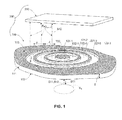
- Fig. 1 is a perspective top view showing a generalized TPV converter 200 comprising a simplified spectrally-selective metamaterial emitter 100 that converts heat energy E S into a highly directional radiant energy beam E R , and an associated PV cell 210 that is fixedly disposed to receive photons transmitted in radiant energy beam E R .
- Spectrally-selective metamaterial emitter 100 generally includes a base substrate 111 and a novel bull's eye (circular target-shaped) structure 120 that is integrally formed on base substrate 111.
- Base substrate 111 is a solid (wall-like) plate having a planar lower (first) surface 112 and an opposing planar upper (second) surface 113 on which bull's eye structure 120 is integrally formed.
- lower surface 112 faces a source of heat energy E S
- upper surface 113 faces away from the heat energy source.
- Base substrate 111 is preferably entirely constructed from metal, and more preferably is entirely constructed using one or more refractory metals (e.g., Rhenium, Tantalum, or Tungsten), or a refractory metal alloy (e.g., Rhenium alloy).
- base substrate 111 has a thickness T on the order of more than a wavelength of emitted radiant energy E R (described below), but may have any arbitrary thickness outside of this constraint.
- Bull's eye structure 120 includes concentric circular ridge structures 121-1, 121-2 and 121-3 that are integrally formed on upper surface 113 of base substrate 111 (i.e., either formed from the same material as base substrate 111 by a subtractive process such as etching or milling, or formed by an additive process such as sputtering that effectively melds (fuses) the added material to the base substrate material).
- Ridge structures 121-1, 121-2 and 121-3 are respectively separated by intervening circular grooves 122-1, 122-2 and 122-3 that extend into (but not through) base substrate 111 such that each adjacent pair of ridge structures is separated by a fixed grating period (pitch distance) A.
- ridge structures 121-1 and 121-2 are separated by circular groove 122-1 such that the distance between an outside edge of ridge structure 121-1 and and outside edge of ridge structure 121-2 is equal to the grating period A.
- ridge structures 121-2 and 121-3 are separated by circular groove 122-2 such that the distance between an outside edge of ridge structure 121-2 and and outside edge of ridge structure 121-3 is equal to the same grating period A as that separating ridge structures 121-1 and 121-2.
- Ridge structures 121-1 to 121-3 comprise metal that may be different from the material that forms base substrate 111, but preferably both the ridge structures and the base substrate comprise the same metal material to avoid thermal mismatch issues.
- bull's eye structure 120 is configured such that, when heat energy E S is applied to lower surface 112 and is sufficient to heat base substrate 111 to a temperature above 1000°K, radiant energy E R is emitted from upper surface 113 having a peak emission wavelength ⁇ peak that is roughly equal to (i.e., within 25% of) fixed grating period A.
- a relationship between the specific geometric dimensions associated with bull's eye structure 120 and the characteristics of emitted radiant energy beam E R are explained in additional detail in co-owned and co-pending U.S. Patent Application Serial Number 14/180,333 , entitled “SPECTRALLY-SELECTIVE METAMATERIAL EMITTER” [Atty Docket No. 20131311US01 (XCP-186-1)], which is incorporated herein by reference in its entirety.
- emitted radiant energy beam E R is highly directional (i.e., 90% of the emitted radiant energy is within 0.5° of perpendicular (angle ⁇ ) to the planar outward-facing surface 113), narrow band (i.e., the full-width at half maximum of the emitted radiant energy is within 10% of peak emission wavelength ⁇ peak ), and peak emission wavelength ⁇ peak that is roughly equal to the fixed grating period A separating each adjacent pair of concentric circular ridge structures (i.e., the peak emission wavelength is within 25% of the grating period ⁇ ).
- metamaterial emitter 100 is selectively “tunable” (adjustable) by way of adjusting the fixed grating period A separating the concentric circular ridge structures 121-1 to 121-3. For example, if a first metamaterial emitter is found to generate radiant energy whose peak wavelength is non-optimal (e.g., too low) for a particular PV cell, then a second metamaterial emitter with an appropriately adjusted (e.g., larger) fixed grating period can be fabricated that generates a higher peak wavelength, thereby effectively "tuning" the radiant energy to the optimal peak wavelength.
- emitter 100 can include grating periods of almost any size, in the exemplary practical embodiment depicted in Fig. 1 (e.g., when used as part of TPV system 200 including a low-bandgap PV cell 210), ridge structures typically has a grating period A in the range of 0.5 microns and 5.0 microns, which corresponds with the absorption curves of most commercially available PV cells.
- a particularly preferred embodiment e.g., when PV cell 210 is a GaSb PV cell having an optimal wavelength range of said PV cell is 1.0 microns to 2.0 microns
- emitter 100 is produced with a grating period ⁇ in the range of 0.5 microns and 3.0 microns.
- metamaterial emitter 100 effectively functions as a narrowband filter element (spectral control element) that only passes in-band photons to an associated target (e.g., photons having wavelengths within the EQE curve of a target PV cell), and is capable of preventing out-of-band photons from reaching the target.
- a narrowband filter element spectral control element
- This filtering function is illustrated in Fig. 1 , where the broadband characteristics of the photons associated with heat energy E S are identified using S-parameter S11 to indicate out-of-band photons, and S-parameter S12 to indicate in-band photons.
- metamaterial emitter 100 effectively "passes” in-band photons S12 to PV cell 120.
- the all-metal structure of metamaterial emitter 100 forms a type of barrier between heat energy E S and PV cell 210 that effectively "blocks" (i.e., prevents out-of-band photons S12 from reaching the PV cell. Note that this filtering functionality would not be possible if base substrate 111 were not a solid sheet (i.e., if the substrate included holes that allowed both S11 and S12 to pass through).
- the present invention greatly increases the efficiency of TPV converter 200 over conventional approaches.
- Fig. 2 is a simplified perspective view showing a TPV converter 200A including a metamaterial emitter 100A having multiple bull's eye structures 120A-11 to 120A-13 and 120A-21 to 120A-23 that are formed on a "target-facing" surface 113A of a base substrate 111A in a manner similar to that described above.
- Figs. 3(A) to 3(C) are cross-sectional views taken along section lines 3A-3A, 3B-3B, and 3C-3C of Fig. 2 .
- Metamaterial emitter 100A is characterized in that it utilizes multiple bull's eye structures arranged in sets of three, where each bull's eye structure of each set has a different fixed grating period to effectively broaden a total radiant energy beam E R-T0TAL emitted by the metamaterial emitter 100A.
- the multiple bull's eye structures are arranged in two sets 120A-1 and 120A-2, where each set includes three bull's eye structures (i.e., set 120A-1 includes bull's eye structures 120A-11 to 120A-13, and set 120A-2 includes bull's eye structures 120A-21 to 120A-23).
- Each set 120A-1 and 120A-2 includes one bull's eye structure having grating period ⁇ 1, one bull's eye structure having grating period ⁇ 2, and one bull's eye structure having grating period ⁇ 3.
- set 120A-1 includes structure 120A-11 having concentric circular ridge structures spaced at a fixed grating period ⁇ 1 (e.g., the distance between adjacent structures 121A-111 and 121A-112 is equal to grating period ⁇ 1).
- Fig. 3(A) also represents bull's eye structure 210A-22 of set 120A-2, which includes ridge structures having fixed grating period ⁇ 1 formed in the same manner depicted by adjacent structures 121A-111 and 121A-112.
- Fig. 3(B) shows that both structure 120A-12 of set 120A-1 and structure 210A-22 of set 120A-2 have grating period ⁇ 2 (e.g., as depicted by adjacent structures 121A-121 and 121A-122, which are separated by grating period ⁇ 2)
- Fig. 3(C) shows that both structure 120A-13 of set 120A-1 and structure 210A-23 of set 120A-2 have grating period ⁇ 3 (e.g., as depicted by adjacent structures 121A-131 and 121A-132, which are separated by grating period ⁇ 3).
- metamaterial emitter 100A with three different grating periods is that this approach can be used to selectively broaden the overall spectrum of the total radiant energy beam E R-TOTAL emitted by metamaterial emitter 100A to associated PV cell 210A. That is, because the radiant energy generated by a particular bull's eye structure is related to its fixed grating period, a broadened the total radiant energy beam E R-TOTAL is generated by emitter 100A (shown in Fig. 2 ) by utilizing three different grating periods ⁇ 1, ⁇ 2 and ⁇ 3. For example, assume fixed grating period ⁇ 3 is larger than fixed grating period ⁇ 2, and fixed grating period ⁇ 2 is larger than fixed grating period ⁇ 1. As indicated in Figs.
- these different grating periods generate component radiant energy beams to having different peak emission wavelengths. That is, because fixed grating period ⁇ 3 is greater than fixed grating period ⁇ 2, component radiant energy beams E R3 emitted from bull's eye structures 120-13 and 120-23 have a peak emission wavelength ⁇ peak3 that is greater than a peak emission wavelength ⁇ peak2 of radiant energy E R2 generated by bull's eye structures 120-12 and 120-22. Similarly, the peak emission wavelength ⁇ peak2 of radiant energy beam E R2 is greater than a peak emission wavelength ⁇ peak1 of radiant energy E R1 generated by bull's eye structures 120-11 and 120-21). Referring again to Fig.
- the total radiant energy beam E R-TOTAL is a combination of component radiant energy beams E R1 , E R2 and E R3 , and the effect of combining the adjacent narrowband spectra of component beams E R1 , E R2 and E R3 is to broaden the overall spectrum of total radiant energy beam E R-TOTAL .
- This approach can be used, for example, to provide more in-band photons to associated PV cell 210A, and consequently to increase the output power density of TPV converter 200A.
- a metamaterial emitter may include only two grating periods to facilitate the emission of a relatively narrow emission spectrum, or a spectrum having two separated "peak" emission wavelengths.
- the use of a large number of grating periods facilitates the emission of a relatively broad emission spectrum.
- Fig. 4 is a perspective view showing a TPV converter 200B having a metamaterial emitter 100B and a PV cell 210B, where metamaterial emitter 100B includes multiple bull's eye structures formed on a "target-facing" surface 113B of a base substrate 111B in a manner similar to that described above.
- Metamaterial emitter 100B differs from the previous embodiments in that the multiple bull's eye structures are formed in a "multiplexed" (overlapping) pattern (i.e., such that at least some of the circular ridge structures of one bull's eye structure intersect at least some of the circular ridge structures of at least one adjacent bull's eye structure). For example, referring to the upper left corner of Fig.
- bull's eye structure 120B-11 includes a first group of concentric circular ridge structures 121B-11
- adjacent bull's eye structure 120B-12 includes a second group of concentric circular ridge structures 121-12.
- Bull's eye structures 120B-11 and 120B-12 form a multiplexed pattern in that at least some of circular ridge structures 121B-11 of bull's eye structure 120B-11 intersect (overlap) at least some of circular ridge structures 121B-12 of bull's eye structure 120B-12.
- This multiplex pattern serves to concentrate radiant energy E R-TOTAL emitted by metamaterial emitter 100B, which can be used, for example, to provide more in-band photons to PV cell 210B, and consequently to increase the output power density of TPV converter 200B.
- metamaterial emitter 100B is also fabricated to employ the multiple-grating-period approach described above with reference to Fig. 2 (i.e., such that at least one bull's eye structure has a fixed grating period that is different (e.g., larger) than the fixed grating period of another bull's eye structure).
- the various multiplexed bull's eye structures of metamaterial emitter 100B are shown as being arranged in three sets: a first set 120B-1 including bull's eye structures 120B-11, 120B-12 and 120B-13, a second set 120B-2 including bull's eye structures 120B-21, 120B-22 and 120B-23, and a third set 120B-3 including bull's eye structures 120B-31, 120B-32 and 120B-33.
- Each set includes one bull's eye structure having a common first grating period (i.e., bull's eye structures 120B-11, 120B-21 and 120B-31 are fabricated using the same grating period in the manner described above with reference to Fig.
- one bull's eye structure having a second grating period i.e., bull's eye structures 120B-12, 120B-22 and 120B-32 are fabricated in the manner described above with reference to Fig. 3(B)
- one bull's eye structure having a third grating period i.e., bull's eye structures 120B-13, 120B-23 and 120B-33 are fabricated in the manner described above with reference to Fig. 3(B) ).
- metamaterial emitter 100B generates total radiant energy E R-TOTAL that both concentrates and combines adjacent narrowband spectra to produce a high energy emission with a broader overall spectrum that maximizes the number of in-band photons supplied to PV cell 210B, thereby maximizing the output power density of PV cell 210B.
- Fig. 5 is a perspective view showing a TPV converter 200C including a metamaterial emitter 100C and two PV cells 210C-1 and 210C-2.
- the "base substrate" of TPV converter 200C is formed as part of a box-like enclosure 110C that facilitates achieving optimal high operating temperatures (i.e., 1000°K to 1500°K).
- Box-like enclosure 110C includes a peripheral wall 111C having an upper (first) peripheral wall portion 111C-1 and a lower (second) peripheral wall portion 111C-2 that are connected by respective side wall portions in an opposing spaced-apart (e.g., parallel) relationship such that a substantially rectangular interior cavity 114C is defined between wall portions 111C-1 and 111C-2.
- Peripheral wall portions 111C-1 and 111C-2 respectively include inward-facing surface portions 112C-1 and 112C-2 that face an interior cavity 114C, and outward-facing surfaces 113C-1 and 113C-2 that face away from interior cavity 114C (i.e., upward and downward, respectively, from box-like enclosure 110C).
- Peripheral wall portions 111C-1 and 111C-2 extend between an inlet end 110C-1 and an outlet end 110C-2 of box-like enclosure 110C such that an inlet opening 115C is defined between respective front end portions 111C-1F and 111C-2F of peripheral wall portions 111C-1 and 111C-2, and an outlet opening 116C is defined between respective rear end portions 111C-1R and 111C-2R of peripheral wall portions 111C-1 and 111C-2.
- “source” heat energy E S is supplied into the interior cavity 114C through inlet opening 115C, and "waste" heat energy is evacuated through outlet opening 116C.
- Metamaterial emitter 100C includes two bull's eye structures 120C-1 and 120C-2 formed in the manner described above that are disposed on outward facing surfaces 113C-1 and 113C-2, respectively.
- bull's eye structure 120C-1 is disposed on upward-facing surface 113C-1 of upper peripheral wall portion 111C-1 and includes concentric circular ridge structures 121C-1 separated by intervening circular grooves 122C-1 and separated by a fixed grating period ⁇ 1
- bull's eye structure 120C-2 is disposed on downward-facing surface 113C-2 of lower peripheral wall portion 111C-2 and includes concentric circular ridge structures 121C-2 separated by intervening circular grooves 122C-2 and separated by a fixed grating period ⁇ 2.
- PV cells 210C-1 and 210C-2 are essentially identical (i.e., having the same spectral response), so fixed grating period ⁇ 2 is the same as fixed grating period ⁇ 1.
- PV cells 210C-1 and 210C-2 have different spectral responses, so fixed grating period ⁇ 2 is different from (e.g., larger or smaller than) fixed grating period ⁇ 1.
- the box-like enclosure arrangement of metamaterial emitter 100C provides optimal energy beam generation because flat/planar peripheral wall portions 111C-1 and 111C-2 facilitate cost-effective fabrication of the bull's eye structures thereon (e.g., using existing photolithographic fabrication techniques), and because rectangular-shaped interior cavity 114C facilitates the efficient transfer of heat energy over the "base substrate" formed by peripheral wall portions 111C-1 and 111C-2.
- the rectangular box-like arrangement facilitates the transfer of heat energy in the form of concentrated sunlight that reflects between the opposing upper and lower interior surfaces 112C-1 and 112C-2, thereby heating peripheral wall portions 111C-1 and 111C-2, and allowing associated waste heat to be removed from interior cavity 114C through outlet opening 116C.
- this arrangement allows TPV converter 200C to provide increased electricity generation over a single PV cell approach.
- the gist of this approach is further expanded to employ additional bull's eye structures and additional PV cells (e.g., disposed along the sides of box-like enclosure 110C, or along multiple surfaces of a non-rectangular box-shaped enclosure) to potentially further increase electricity generation.
- box-like enclosure 110C is constructed as an all-metal structure (e.g., constructed from a single metal block or by welding or otherwise securing four metal plates together).
- the all-metal structure facilitates achieving the required high operating temperatures (i.e., 1000 to 1500°K) over a suitable operating lifetime of metamaterial emitter 100C.
- the all-metal box-like enclosure 110C is formed entirely using one or more refractory metals (e.g., Rhenium, Tantalum or Tungsten) or refractory metal alloys to further enhance the enclosure's operational lifetime.
- Figs. 6(A) and 6(B) are perspective and cross-sectional side views showing a TPV converter 200D including a metamaterial emitter 100D and two PV cells 210D-1 and 210D-2 arranged in accordance with another embodiment.
- metamaterial emitter 100D includes an all-metal box-like enclosure 110D that is configured for use in a solar tower power harvesting system such as that described in co-owned and co-pending U.S. Patent Application Serial Number xx/xxx,xxx, entitled “Solar Tower Power Harvesting System With Metamaterial Enhanced Solar Thermophotovoltaic Converter (MESTC)" [Atty Docket No. 20131311US03 (XCP-186-3)], which is incorporated herein by reference in its entirety.
- MESTC Metal Enhanced Solar Thermophotovoltaic Converter
- Metamaterial emitter 100D is similar to that described above with reference to Fig. 5 in that box-like enclosure 110D includes opposing upper (first) and lower (second) peripheral wall portions 111D-1 and 111D-2 that are connected by respective side wall portions in an opposing spaced-apart (e.g., parallel) relationship, and such that arrays 120D-1 and 120D-2 of bull's eye structures are respectively formed on outward-facing surfaces 113D-1 and 113D-2 of wall portions 111D-1 and 111D-2.
- Bull's eye structure arrays 120D-1 and 120D-2 are implemented using any of the various arrangements described above, but preferably include a multiplexed arrangement such as that shown in Fig. 4 to maximize the amount of energy transmitted in emitted radiant energy beams E R1 and E R2 .
- Metamaterial emitter 100D differs from previous embodiments in that it includes a compound parabolic trough 117D disposed at the inlet end of box-like enclosure 110D.
- the compound parabolic trough includes an upper (first) compound parabolic trough structure 117D-1 integrally connected to a front end portion 111D-1F of upper peripheral wall portion 111D-1, and a lower (second) compound parabolic trough structure 117D-2 integrally connected to a front end portion 111D-2F of lower peripheral wall portion 111D-2.
- the compound parabolic trough includes an upper (first) compound parabolic trough structure 117D-1 integrally connected to a front end portion 111D-1F of upper peripheral wall portion 111D-1, and a lower (second) compound parabolic trough structure 117D-2 integrally connected to a front end portion 111D-2F of lower peripheral wall portion 111D-2.
- compound parabolic trough structures 117D-1 and 117D-2 are operably shaped to channel concentrated sunlight E S through the inlet opening 115D into interior cavity 114D between peripheral wall portions 111D-1 and 111D-2 such that the sunlight reflects between the inside surfaces 112D-212 and 112D-222 of peripheral wall portions 111D-1 and 111D-2 in a manner that maximizes the transfer of heat energy to bull's eye structure arrays 120D-1 and 120D-2, which in turn maximizes the amount of radiant energy emitted in beams E R1 and E R2 respectively emitted from bull's eye structure arrays 120D-1 and 120D-2 to PV cells 210D-1 and 210D-2, respectively.
- Metamaterial emitter 100D also differs from previous embodiments in that it includes a funnel-shaped outlet 117D disposed at the outlet end of box-like enclosure 110D that serves to control the release of "waste" heat from interior cavity 114D.
- the funnel-shaped outlet includes an upper (first) funnel-shaped outlet structure 118D-1 integrally connected to a rear end portion 111D-1R of upper peripheral wall portion 111D-1, and a lower (second) funnel-shaped outlet structure 118D-2 integrally connected to a rear end portion 111D-2R of lower peripheral wall portion 111D-2.
- funnel-shaped outlet structures 118D-1 and 118D-2 are operably shaped to channel "waste" heat energy E W from interior cavity 114D through outlet opening 116D at a rate that optimizes energy transfer to bull's eye structure arrays 120D-1 and 120D-2.
- the entirety of all-metal box-like enclosure 110D is constructed using metal, and more preferably using a single refractory metal (e.g., Rhenium, a Rhenium alloy, Tantalum or Tungsten).
- a single refractory metal e.g., Rhenium, a Rhenium alloy, Tantalum or Tungsten.
- Fig. 7 is a flow diagram showing a generalized method for producing a TPV converter according to another embodiment of the present invention.
- the production method applies to any of the TPV converters described with reference to Figs. 1 to 6(B) , that is, including a spectrally-selective metamaterial emitter having one or more bull's eye structures and an associated PV cell.
- the production method begins by determining the optimal conversion spectrum (e.g., from a previously generated EQE curve, or through testing) of the associated PV cell.
- the optimal conversion spectrum identifies "in-band" photon wavelengths that are most efficiently converted by the associated PV cell into electricity, and varies by PV cell type.
- the production process then involves fabricating a spectrally-selective metamaterial emitter with bull's eye structures having concentric circular ridge structures separated by a fixed grating period that is roughly equal to the PV cell's optimal conversion spectrum.
- this portion of the production process is carried out as set forth with reference to Figs. 8(A) to 8(F) , which illustrate fabricating a spectrally-selective metamaterial emitter using photolithographic processing techniques.
- Figs. 8(A) to 8(D) illustrate the use of photolithography to generate a patterned mask on a planar upper surface 113 of a solid base substrate 111 (shown in Fig. 8(A) .
- base substrate 111 comprises one of the refractory metals (or alloys thereof) that are mentioned above.
- Fig. 8(B) shows the deposition of a photoresist 210 that forms a photoresist layer 215 on upper surface 113 of base substrate 111.
- FIG. 8(C) depicts the subsequent use of a reticle 220 to expose photoresist layer 215 using known techniques, but modified in that reticle includes an aperture pattern having a "mirror" shaped pattern corresponding to a "negative" of the desired bull's eye structures (i.e., including concentric circular apertures 222 set at a grating period in the range of 10 nanometers to 5 microns), whereby light 225 passing through apertures 222 develop corresponding concentric circular portions of photoresist layer 215.
- a reticle 220 to expose photoresist layer 215 using known techniques, but modified in that reticle includes an aperture pattern having a "mirror" shaped pattern corresponding to a "negative" of the desired bull's eye structures (i.e., including concentric circular apertures 222 set at a grating period in the range of 10 nanometers to 5 microns), whereby light 225 passing through apertures 222 develop corresponding concentric circular portions of photoresist layer 215.
- photoresist mask 230 including a plurality of concentric circular resist structures 231 having a fixed grating period ⁇ in the range of 0.5 to 5 microns, wherein each adjacent pair of concentric circular resist structures 231 are separated by an intervening concentric circular slot 232.
- Fig. 8(E) depicts utilizing mask 230 to form a bull's eye structure on upper surface 113 according to a specific "additive" embodiment of the present invention.
- a refractory metal 240 (which can either be the same refractory metal as forming base substrate 111 or a different refractory metal) is deposited (e.g., by way of sputter deposition) over mask 230 and exposed portions of upper surface 113 that are exposed between concentric circular resist structures 231, thereby forming ridge structures 121 having the fixed grating period A between adjacent pairs of resist structures 231.
- mask 230 is utilized to form bull's eye structures by dry etching exposed portions of the base substrate through the mask slots, thereby forming the concentric grooves between corresponding circular ridge structures 121-2 that have a composition identical to that of the base substrate.
- Fig. 8(F) depicts the subsequent removal of the photoresist mask using a suitable etchant 250 mask 230 from the planar upper surface 113, thereby completing the fabrication of metamaterial emitter 100 including a bull's eye structure 120 disposed on base substrate 111, where bull's eye structure 120 includes concentric circular ridge structures 121-2 separated by intervening circular grooves 122 and spaced at a grating period A in the range of 0.5 to 5 microns.
- final construction of the metamaterial emitter is completed, and then (as indicated in block 403), the PV cell (or PV cells) are operably secured in a fixed relationship relative to the metamaterial emitter such that radiant energy generated by the bull's eye structures is directed onto the PV cell(s) for conversion into electricity.
- Final construction of the metamaterial emitter may include, for example, connecting the metal plate (base substrate) on which the bull's eye structures are formed into a box-like enclosure similar to those described above.
- Securing the PV cells may involve, for example, mounting the PV cells directly to the box-like enclosure, mounting the PV cells onto a water-cooled platform disposed adjacent to the metamaterial emitter, or at a suitable distance from the metamaterial emitter that minimizes heat damage of the PV cell.
- a reticle is produced in which a concentric circular pattern is repeated in an overlapping manner to form apertures having a multiplexed arrangement, and then the reticle is used to generate a patterned mask including concentric circular resist structures disposed in the multiplexed arrangement, and then using the process described above to form multiple pluralities of overlapping concentric circular metal ridge structures in the multiplexed arrangement.
- TPV converters described herein include metamaterial emitters having all-metal structures to maximize operational lifetime
- TPV converters utilizing less robust metamaterial emitters e.g., having metal bull's eyes structures formed on dielectric base substrates or all-semiconductor platforms
Landscapes
- Physics & Mathematics (AREA)
- Engineering & Computer Science (AREA)
- General Physics & Mathematics (AREA)
- Condensed Matter Physics & Semiconductors (AREA)
- Computer Hardware Design (AREA)
- Electromagnetism (AREA)
- Microelectronics & Electronic Packaging (AREA)
- Power Engineering (AREA)
- Chemical & Material Sciences (AREA)
- Nanotechnology (AREA)
- Crystallography & Structural Chemistry (AREA)
- Manufacturing & Machinery (AREA)
- Optics & Photonics (AREA)
- Photovoltaic Devices (AREA)
Abstract
Description
- This invention relates to apparatus and methods for generating electricity using thermophotovoltaic energy conversion.
- Thermophotovoltaic (TPV) energy conversion involves the conversion of heat to electricity, and has been identified as a promising technology since the 1960's. A basic TPV system includes a thermal emitter and a photovoltaic diode receiver. The thermal emitter is typically a piece of solid material or a specially engineered structure that generates thermal emission when heated to a high temperature (i.e., typically in a range from about 1200°K to about 1500°K). Thermal emission is the spontaneous radiation (emission) of photons due to thermal motion of charges in the thermal emitter material. For normal TPV system operating temperatures, the radiated photons are mostly at near infrared and infrared frequencies. The photovoltaic diode receiver includes a photovoltaic (PV) cell positioned to absorb some of these radiated photons, and is constructed to convert the absorbed photons into free charge carriers (i.e., electricity) in the manner typically associated with conventional solar cells. In effect, a solar energy system is a type of TPV energy conversion system where the sun acts as the thermal emitter. However, the present invention is directed to "earth-bound" TPV energy conversion systems in which the thermal emitter is solid structure that is heated from an external source (e.g., by concentrated sunlight or other heat generator).
- Although TPV energy conversion is promising in theory, practical conventional TPV systems have achieved far lower efficiencies than theoretically predicted. A TPV system can be modeled as a heat engine in which the hot body (i.e., the heated thermal emitter) is described as a blackbody radiation source having a black body temperature TBB, and the relatively cold PV receiver has a temperature T PV, whereby the theoretical thermodynamic efficiency limit is given by the Carnot cycle η Carnot = (T BB-T PV)/T BB. For a thermal emitter temperature T BB equal to 1500°K and a PV receiver temperature T PV equal to 300°K, a theoretical efficiency η Carnot equals 0.8 (80%), which exceeds the Shockley-Queisser limit (i.e., the maximum theoretical efficiency of a solar cell using a p-n junction to collect power). In reality, however, the efficiencies of conventional TPV systems are reported to be below 10%. This is believed to stem from a mismatch between the spectrum of the thermal emitter and the PV cell.
- One reason for the lower realized efficiencies of conventional TPV systems is related to carrier thermalization at high temperatures caused by a mismatch between the emitted photons and the PV cells. Thermal radiation from the thermal emitter (hot body) of a TPV system has a spectral power density given by Planck's law, and the peak wavelength λ max is given by Wien's law (λ max ∼ (2898/T BB) µm). For high-temperature emitters (1100°K ≤T BB ≤1500°K), the peak wavelength λ max is in the range of 1.9 to 2.6 µm, which requires the TPV system to utilize PV cells having low bandgap semiconductors (i.e., around 0.5-0.8 eV). Using such low bandgap PV cells requires the use of emitter materials having bandgaps closer to 0.5 eV (∼2.5 µm) in order to obtain a larger fraction of in-band photons at reasonable emitter temperatures (i.e., 1100-1500°K). If emitter materials having bandgaps below 0.5 eV are used, the PV cell performance suffers from high carrier thermalization at the elevated temperatures required in TPV systems.
- What is needed is a thermophotovoltaic (TPV) converter that overcomes the problems set forth above and converts heat energy to electricity with a much higher efficiency than achieved using conventional TPV approaches. What is particularly needed is a TPV converter that achieves efficiencies of at least 25% with a wide variety of different PV cell types.
- The present invention is directed to a TPV converter that utilizes a spectrally-selective metamaterial emitter and an associated PV cell to convert heat energy (e.g., concentrated sunlight or heat from combustion process) into electrical energy (electricity) with efficiencies that are much higher than those achieved using conventional TPV approaches. The spectrally-selective metamaterial emitter includes a novel bull's eye (circular target-shaped) structure that converts heat energy into a highly directional, narrow bandwidth radiant energy beam having a peak emission wavelength that is roughly equal to a fixed grating period separating concentric circular ridge structures that form the bull's eye structure. By fabricating a spectrally-selective metamaterial emitter including bull's eye structures having a fixed grating period that roughly equals (or overlaps) the EQE curve (optimal conversion spectrum) of the associated ("matched") PV cell, the TPV converter achieves an efficiency of 25% or higher at elevated operating temperatures of more than 1400°K. Moreover, because the peak emission wavelength of the radiant energy beam is easily changed by way of changing the fixed grating period, the spectrally-selective metamaterial emitter is effectively "tunable" (adjustable) to match the optimal conversion spectrums of different PV cell types.
- According to a generalized embodiment of the present invention, the TPV converter utilizes a spectrally-selective metamaterial emitter having one or more bull's eye structures disposed on a planar surface of a plate-like (solid) base substrate, and an associated PV cell disposed in a fixed relationship to receive the radiant energy beam emitted from the bull's eye structure(s). Each bull's eye structure includes multiple concentric circular ridge structures that extend from the planar surface of the base substrate and are separated by intervening circular grooves, where each adjacent pair of ridge structures is separated by a fixed grating period. The associated PV cell includes one or more semiconducting materials that convert light to electricity by capturing (absorbing) "in-band" photons (i.e., photons having certain energies/wavelengths that are conducive to capture by the PV cell's particular semiconducting material composition) in way that generates electron-hole pairs, which are then separated for extraction. The "in-band" photons associated with the PV cell are photons that have energies/wavelengths within the PV cell's optimal conversion spectrum (i.e., as determined by the PV cell's External Quantum Efficiency (EQE) curve), which in part depends on the associated PV cell's composition). The associated PV cell's efficiency (i.e., the ratio of photons absorbed/converted over the total number of incident photons) is directly related to the percentage of incident photons that are "in-band" photons (i.e., photons having energies within its optimal conversion spectrum). That is, each PV cell converts "in-band" photons at a higher efficiency than "out-of-band" photons (i.e., photons having energies outside the optimal conversion spectrum). According to an aspect of the present invention, the bull's eye structure is configured to "match" the EQE curve of the associated PV cell by fabricating the bull's eye structure with a fixed grating period that is roughly equal to the wavelength of an "in-band" photon that is within the optimal absorption spectrum of the associated PV cell. Accordingly, when the metamaterial emitter is heated to a temperature above 1000°K, a radiant energy beam emitted from the bull's eye structure has a peak emission wavelength that is within the associated PV cell's optimal conversion spectrum, whereby the spectrally-selective metamaterial emitter is "matched" to the associated PV cell in the sense that a high percentage of the photons forming the radiant energy beam are absorbable/convertible by the associated PV cell. Further, when the metamaterial emitter is heated to a temperature above 1400°K, the overall efficiency of the TPV emitter is increased to 25% or higher.
- In accordance with an embodiment of the present invention, a TPV converter utilizing a low-bandgap PV cell having "in-band" photons that are in the optimal conversion wavelength range of 0.5 microns to 3 microns. In order to generate/emit a high percentage of in-band photons for such low-bandgap PV cells, the metamaterial emitter is fabricated to include bull's eye structures having fixed grating periods in the range of 10 nanometers and 5 microns. In a presently preferred embodiment, a metamaterial emitter is produced with bull's eye structures having a grating period in the range of 0.5 to 3.0 microns (e.g., 1.5 microns) in order to match the specific absorption curve of a selected low-bandgap (e.g., GaSb) PV cell having a cell-specific optimal conversion wavelength range of 1.0 to 2.0 microns. By determining the optimal wavelength range of a PV cell and then fabricating a "matching" spectrally-selective metamaterial emitter (i.e., including bull's eye structures having one or more fixed grating periods that are within the determined associated optimal wavelength range), the present invention facilitates the production of high-efficiency TPV converters that utilize a wide range of PV cell types, thereby facilitating a strategic selection of the associated PV cell type (e.g., based on low-cost or high-performance) without sacrificing converter efficiency.
- According to an aspect of the present invention, the entire metamaterial thermal emitter (i.e., both the base substrate and the bull's eye" structure) are entirely formed using one or more metals. This all-metal construction is critical for withstanding high optimal operating temperatures (i.e., 1000 to 1500°K) without delamination (which can occur when one or more dielectric are used), and because metallic surfaces support surface plasmons (or spoof surface plasmons) that are required to facilitate the efficient emission of the highly directional, narrow band radiant energy and having the desired peak emission wavelength. In a specific embodiment, both the base substrate and the bull's eye" structure are entirely formed using one or more refractory metals (e.g., Rhenium, Tantalum or Tungsten), or metal alloys, because these metals are able to withstand the higher operating temperatures (i.e., approaching 1500°K) without melting or deforming. In a presently preferred embodiment, both the base substrate and the bull's eye" structure are entirely formed using Rhenium or a Rhenium alloy because the ability of this metal/alloy to withstand high temperatures is well known from their use in high-performance jet and rocket engines.
- According to a specific embodiment of the present invention, the metamaterial thermal emitter of a TPV converter is configured to include multiple bull's eye structures disposed in an array of the base substrate in order to produce radiant energy beam with a broad spectral bandwidth, in order to increase the number of in-band photons that are efficiently converted by the associated PV cell into electricity. In a specific embodiment, the bull's eye structures are disposed in sets of two or more, with each bull's eye structure of each set having a corresponding fixed grating period between adjacent concentric circular ridges that is different from the fixed grating periods of the other bull's eye structures of that set. In an exemplary embodiment, the associated PV cell is a low-bandgap PV cell having a bandgap of approximately 1.72 microns, and each set includes three bull's eye structures respectively having concentric circular ridges that are formed with corresponding fixed grating periods that are equal to 1.3 microns, 1.5 microns and 1.7 microns, respectively. The different bull's eye structures of each set emit a mix of photons having the various wavelengths determined by the different grating periods, thereby producing a broadened emission spectrum that increases the number of in-band photons for conversion by the associated PV cell.
- In another specific embodiment, a metamaterial emitterof a TPV converter is configured to include an array of bull's eye structures arranged in a multiplexed (overlapping) pattern (i.e., such that at least some of the concentric circular ridge structures of each bull's eye structure intersect at least some of the concentric circular ridge structures of an adjacent bull's eye structure, thereby concentrating the emitted radiant energy to increase spectral bandwidth. Further, by disposing the bull's eye structures in sets having different fixed grating periods, as described above, the metamaterial emitter both concentrates and combines adjacent narrowband spectra to produce a high energy emission with a broader overall spectrum that can be used, for example, to maximize the number of in-band photons converted by a target PV cell, thereby maximizing the PV cell's output power density.
- According to an exemplary practical embodiment of the present invention, the metamaterial emitter of a TPV converter includes a box-like enclosure formed by a peripheral wall, with one or more bull's eye structures disposed as described above on at least two outward facing surfaces of the peripheral wall (i.e., such that at least two radiant energy beams are emitted in at least two (e.g., upward and downward) directions from the metamaterial emitter), and the TPV converter further includes at least two PV cells positioned to receive the at least two radiant energy beams. The peripheral wall of the emitter's box-like enclosure surrounds a substantially rectangular interior cavity and includes an inlet opening through which heat energy (e.g., concentrated sunlight) is supplied into the cavity during operation, and an outlet opening through which waste heat is allowed to exit the cavity. Each bull's eye structure is configured to generate a radiant energy beam that is matched to the associated PV cell positioned to receive the radiant energy beam. In one embodiment, the box-like enclosure is an all-metal structure to facilitate the required high operating temperatures (i.e., 1000 to 1500°K) without delamination (which can occur with metal/dielectric structures). In a specific embodiment, the all-metal box-like enclosure is formed entirely from refractory metals (e.g., Rhenium, Tantalum or Tungsten) to further enhance the enclosure's operational lifetime. In another specific embodiment, at least one bull's eye structure is disposed on the outward-facing surfaces of two opposing (e.g., upper and lower) peripheral wall portions, thereby generating two radiant energy beams that are directed in different directions from the metamaterial emitter. This arrangement provides optimal energy beam generation because the flat/planar wall surfaces facilitate cost-effective fabrication of the bull's eye structures (i.e., using existing photolithographic fabrication techniques), and the rectangular-shaped interior cavity defined between the two opposing flat peripheral wall portions facilitates efficient transfer of heat energy (e.g., by allowing concentrated sunlight to reflect between the opposing interior surfaces as it propagates along the interior cavity).
- In yet another specific embodiment optimized for converting concentrated solar energy into infrared emissions, the all-metal box-like enclosure is configured to channel solar energy into the interior cavity defined between the two opposing peripheral wall portions in a manner that maximizes the transfer of heat energy to the peripheral wall portions, which in turn maximizes the amount of radiant energy emitted in first and second radiant energy beam respectively emitted from the bull's eye structures formed on the respective outward-facing surfaces to two associated PV cells fixedly positioned to receive the first and second radiant energy beams, respectively. First, a compound parabolic trough is formed by corresponding metal structures that are respectively integrally connected to corresponding front end portions of the opposing peripheral wall portions, wherein the compound parabolic trough is operably shaped to channel concentrated sunlight through the inlet opening into the interior cavity such that it reflects between the inside surfaces of the two opposing peripheral wall portions. In addition, a funnel-shaped outlet is formed by corresponding metal structures respectively integrally connected to the rear end portions of the peripheral wall portions that releases waste heat from interior cavity through the outlet opening in a manner that enhances energy transfer to the bull's eye structures. To maximize the amount of emitted radiant energy, multiple multiplexed bull's eye structures are formed in arrays as described above on the outward-facing surfaces of the peripheral wall portions. To minimize thermal cycling stresses and to maximize the operating lifetime of the metamaterial emitter, the entire all-metal box-like enclosure (i.e., including the peripheral wall portions, the compound parabolic trough structures, and the funnel-shaped outlet structures) are constructed using a refractory metal (e.g., Rhenium, Tantalum or Tungsten) or a refractory metal alloy (e.g., Rhenium alloy).
- In yet another embodiment of the present invention, a TPV converter is produced by determining an optimal conversion spectrum (wavelength range) associated with in-band photons converted by a PV cell into electricity, and then fabricating a spectrally-selective metamaterial emitter by generating a patterned mask on a planar surface of a refractory metal substrate by way of photolithography such that the patterned mask includes concentric circular resist structures having a fixed grating period that is roughly equal to the predetermined optimal wavelength, then utilizing the mask to form concentric circular refractory metal ridge structures on the planar surface having the fixed grating period. In alternative embodiments, the concentric circular ridge structures are formed either using an additive process (e.g., where refractory metal, which can be the same or different from the base substrate, is deposited by way of sputtering or other technique into slots formed in the mask) or a subtractive process (e.g., where the base substrate is dry etched through the mask slots, whereby the concentric ridge structures comprise the same refractory metal as the base substrate). To generate multiplexed bull's eye structures, the mask is formed with concentric circular resist structures disposed in the desired multiplexed arrangement. After forming the concentric circular ridge structures, the mask is removed to expose the intervening concentric circular grooves separating the ridges, thereby completing fabrication of one or more bull's eye structures that generates radiant energy whose peak emission wavelength is "matched" to the optimal conversion spectrum of the PV cell. Once fabrication of the spectrally-selective metamaterial emitter is completed, the PV cell is fixedly mounted over the one or more bull's eye structures, thereby completing production of the TPV converter.
- These and other features, aspects and advantages of the present invention will become better understood with regard to the following description, appended claims, and accompanying drawings, where:
-
Fig. 1 is a perspective view showing a partial TPV converter according to an embodiment of the present invention; -
Fig. 2 is a perspective view showing a TPV converter according to a second embodiment of the present invention; -
Figs. 3(A), 3(B) and 3(C) are cross-sectional side views taken along section lines 3A-3A, 3B-3B and 3C-3C, respectively, ofFig. 2 showing bull's eye structures with different fixed grating periods; -
Fig. 4 is a perspective view showing a TPV converter according to a third embodiment of the present invention; -
Fig. 5 is a perspective view showing a TPV converter according to a fourth embodiment of the present invention; -
Figs. 6(A) and6(B) are perspective and cross-sectional side views showing a TPV converter according to a fifth embodiment of the present invention; -
Fig. 7 is a flow diagram showing a generalized method for producing a TPV converter according to another embodiment of the present invention; and -
Figs. 8(A), 8(B), 8(C), 8(D), 8(E) and 8(F) are simplified cross-sections illustrating a method for fabricating bull's eye structures according to a specific embodiment of the method ofFig. 7 . - The present invention relates to an improvement in TPV (heat-to-electricity) converters. The following description is presented to enable one of ordinary skill in the art to make and use the invention as provided in the context of a particular application and its requirements. As used herein, directional terms such as "upper", "upward", "lower", "downward", "over", "under", "front" and "rear", are intended to provide relative positions for purposes of description, and are not intended to designate an absolute frame of reference. In addition, the phrases "integrally formed" and "integrally connected" are used herein to describe the connective relationship between two portions of a single fabricated or machined structure, and are distinguished from the terms "connected" or "coupled" (without the modifier "integrally"), which indicates two separate structures that are joined by way of, for example, adhesive, fastener, clip, or movable joint. Various modifications to the preferred embodiment will be apparent to those with skill in the art, and the general principles defined herein may be applied to other embodiments. Therefore, the present invention is not intended to be limited to the particular embodiments shown and described, but is to be accorded the widest scope consistent with the principles and novel features herein disclosed.
-
Fig. 1 is a perspective top view showing ageneralized TPV converter 200 comprising a simplified spectrally-selective metamaterial emitter 100 that converts heat energy ES into a highly directional radiant energy beam ER, and an associatedPV cell 210 that is fixedly disposed to receive photons transmitted in radiant energy beam ER. - Spectrally-
selective metamaterial emitter 100 generally includes abase substrate 111 and a novel bull's eye (circular target-shaped)structure 120 that is integrally formed onbase substrate 111. -
Base substrate 111 is a solid (wall-like) plate having a planar lower (first)surface 112 and an opposing planar upper (second)surface 113 on which bull'seye structure 120 is integrally formed. During operation,lower surface 112 faces a source of heat energy ES, andupper surface 113 faces away from the heat energy source.Base substrate 111 is preferably entirely constructed from metal, and more preferably is entirely constructed using one or more refractory metals (e.g., Rhenium, Tantalum, or Tungsten), or a refractory metal alloy (e.g., Rhenium alloy). In an exemplary practical exemplary embodiment (e.g., when used as part of TPV system 200),base substrate 111 has a thickness T on the order of more than a wavelength of emitted radiant energy ER (described below), but may have any arbitrary thickness outside of this constraint. - Bull's
eye structure 120 includes concentric circular ridge structures 121-1, 121-2 and 121-3 that are integrally formed onupper surface 113 of base substrate 111 (i.e., either formed from the same material asbase substrate 111 by a subtractive process such as etching or milling, or formed by an additive process such as sputtering that effectively melds (fuses) the added material to the base substrate material). Ridge structures 121-1, 121-2 and 121-3 are respectively separated by intervening circular grooves 122-1, 122-2 and 122-3 that extend into (but not through)base substrate 111 such that each adjacent pair of ridge structures is separated by a fixed grating period (pitch distance) A. For example, ridge structures 121-1 and 121-2 are separated by circular groove 122-1 such that the distance between an outside edge of ridge structure 121-1 and and outside edge of ridge structure 121-2 is equal to the grating period A. Similarly, ridge structures 121-2 and 121-3 are separated by circular groove 122-2 such that the distance between an outside edge of ridge structure 121-2 and and outside edge of ridge structure 121-3 is equal to the same grating period A as that separating ridge structures 121-1 and 121-2. Ridge structures 121-1 to 121-3 comprise metal that may be different from the material that formsbase substrate 111, but preferably both the ridge structures and the base substrate comprise the same metal material to avoid thermal mismatch issues. - According to an aspect of the present invention, bull's
eye structure 120 is configured such that, when heat energy ES is applied tolower surface 112 and is sufficient to heatbase substrate 111 to a temperature above 1000°K, radiant energy ER is emitted fromupper surface 113 having a peak emission wavelength λpeak that is roughly equal to (i.e., within 25% of) fixed grating period A. A relationship between the specific geometric dimensions associated with bull'seye structure 120 and the characteristics of emitted radiant energy beam ER are explained in additional detail in co-owned and co-pendingU.S. Patent Application Serial Number 14/180,333 , entitled "SPECTRALLY-SELECTIVE METAMATERIAL EMITTER" [Atty Docket No. 20131311US01 (XCP-186-1)], which is incorporated herein by reference in its entirety. - According to another aspect of the present invention, emitted radiant energy beam ER is highly directional (i.e., 90% of the emitted radiant energy is within 0.5° of perpendicular (angle θ) to the planar outward-facing surface 113), narrow band (i.e., the full-width at half maximum of the emitted radiant energy is within 10% of peak emission wavelength λpeak ), and peak emission wavelength λpeak that is roughly equal to the fixed grating period A separating each adjacent pair of concentric circular ridge structures (i.e., the peak emission wavelength is within 25% of the grating period Λ). Accordingly,
metamaterial emitter 100 is selectively "tunable" (adjustable) by way of adjusting the fixed grating period A separating the concentric circular ridge structures 121-1 to 121-3. For example, if a first metamaterial emitter is found to generate radiant energy whose peak wavelength is non-optimal (e.g., too low) for a particular PV cell, then a second metamaterial emitter with an appropriately adjusted (e.g., larger) fixed grating period can be fabricated that generates a higher peak wavelength, thereby effectively "tuning" the radiant energy to the optimal peak wavelength. - Although
emitter 100 can include grating periods of almost any size, in the exemplary practical embodiment depicted inFig. 1 (e.g., when used as part ofTPV system 200 including a low-bandgap PV cell 210), ridge structures typically has a grating period A in the range of 0.5 microns and 5.0 microns, which corresponds with the absorption curves of most commercially available PV cells. In a particularly preferred embodiment (e.g., whenPV cell 210 is a GaSb PV cell having an optimal wavelength range of said PV cell is 1.0 microns to 2.0 microns),emitter 100 is produced with a grating period Λ in the range of 0.5 microns and 3.0 microns. - According to another aspect of the present invention,
metamaterial emitter 100 effectively functions as a narrowband filter element (spectral control element) that only passes in-band photons to an associated target (e.g., photons having wavelengths within the EQE curve of a target PV cell), and is capable of preventing out-of-band photons from reaching the target. This filtering function is illustrated inFig. 1 , where the broadband characteristics of the photons associated with heat energy ES are identified using S-parameter S11 to indicate out-of-band photons, and S-parameter S12 to indicate in-band photons. Because bull'seye structure 120 is "tuned" to the EQE curve ofPV cell 210,metamaterial emitter 100 effectively "passes" in-band photons S12 toPV cell 120. Conversely, the all-metal structure ofmetamaterial emitter 100 forms a type of barrier between heat energy ES andPV cell 210 that effectively "blocks" (i.e., prevents out-of-band photons S12 from reaching the PV cell. Note that this filtering functionality would not be possible ifbase substrate 111 were not a solid sheet (i.e., if the substrate included holes that allowed both S11 and S12 to pass through). By passing only in-band photons to associatedPV cell 210, the present invention greatly increases the efficiency ofTPV converter 200 over conventional approaches. -
Fig. 2 is a simplified perspective view showing aTPV converter 200A including ametamaterial emitter 100A having multiple bull'seye structures 120A-11 to 120A-13 and 120A-21 to 120A-23 that are formed on a "target-facing"surface 113A of abase substrate 111A in a manner similar to that described above.Figs. 3(A) to 3(C) are cross-sectional views taken along section lines 3A-3A, 3B-3B, and 3C-3C ofFig. 2 . -
Metamaterial emitter 100A is characterized in that it utilizes multiple bull's eye structures arranged in sets of three, where each bull's eye structure of each set has a different fixed grating period to effectively broaden a total radiant energy beam ER-T0TAL emitted by themetamaterial emitter 100A. Referring toFig. 2 , the multiple bull's eye structures are arranged in twosets 120A-1 and 120A-2, where each set includes three bull's eye structures (i.e., set 120A-1 includes bull'seye structures 120A-11 to 120A-13, and set 120A-2 includes bull'seye structures 120A-21 to 120A-23). Each set 120A-1 and 120A-2 includes one bull's eye structure having grating period Λ1, one bull's eye structure having grating period Λ2, and one bull's eye structure having grating period Λ3. Specifically, as indicated inFig. 3(A) , set 120A-1 includesstructure 120A-11 having concentric circular ridge structures spaced at a fixed grating period Λ1 (e.g., the distance betweenadjacent structures 121A-111 and 121A-112 is equal to grating period Λ1).Fig. 3(A) also represents bull'seye structure 210A-22 ofset 120A-2, which includes ridge structures having fixed grating period Λ1 formed in the same manner depicted byadjacent structures 121A-111 and 121A-112. Similarly,Fig. 3(B) shows that bothstructure 120A-12 of set 120A-1 andstructure 210A-22 ofset 120A-2 have grating period Λ2 (e.g., as depicted byadjacent structures 121A-121 and 121A-122, which are separated by grating period Λ2), andFig. 3(C) shows that bothstructure 120A-13 of set 120A-1 andstructure 210A-23 ofset 120A-2 have grating period Λ3 (e.g., as depicted byadjacent structures 121A-131 and 121A-132, which are separated by grating period Λ3). - The benefit of forming
metamaterial emitter 100A with three different grating periods is that this approach can be used to selectively broaden the overall spectrum of the total radiant energy beam ER-TOTAL emitted bymetamaterial emitter 100A to associatedPV cell 210A. That is, because the radiant energy generated by a particular bull's eye structure is related to its fixed grating period, a broadened the total radiant energy beam ER-TOTAL is generated byemitter 100A (shown inFig. 2 ) by utilizing three different grating periods Λ1, Λ2 and Λ3. For example, assume fixed grating period Λ3 is larger than fixed grating period Λ2, and fixed grating period Λ2 is larger than fixed grating period Λ1. As indicated inFigs. 3(A) to 3(C) , these different grating periods generate component radiant energy beams to having different peak emission wavelengths. That is, because fixed grating period Λ3 is greater than fixed grating period Λ2, component radiant energy beams ER3 emitted from bull's eye structures 120-13 and 120-23 have a peak emission wavelength λpeak3 that is greater than a peak emission wavelength λpeak2 of radiant energy ER2 generated by bull's eye structures 120-12 and 120-22. Similarly, the peak emission wavelength λpeak2 of radiant energy beam ER2 is greater than a peak emission wavelength λpeak1 of radiant energy ER1 generated by bull's eye structures 120-11 and 120-21). Referring again toFig. 2 , the total radiant energy beam ER-TOTAL is a combination of component radiant energy beams ER1, ER2 and ER3, and the effect of combining the adjacent narrowband spectra of component beams ER1, ER2 and ER3 is to broaden the overall spectrum of total radiant energy beam ER-TOTAL. This approach can be used, for example, to provide more in-band photons to associatedPV cell 210A, and consequently to increase the output power density ofTPV converter 200A. - The approach set forth above with reference to
Figs. 2 and 3(A) to 3(C) is extendible to any number of fixed grating periods in order to selectively broaden the overall spectrum of a total radiant energy beam. That is, although the approach is described with reference to six bull's eye structures disposed in two sets of three that utilize three different grating periods, it is understood that the approach is extendable to any number of bull's eye structures disposed in any number of sets of two or more bull's eye structures. For example, a metamaterial emitter may include only two grating periods to facilitate the emission of a relatively narrow emission spectrum, or a spectrum having two separated "peak" emission wavelengths. Alternatively, the use of a large number of grating periods facilitates the emission of a relatively broad emission spectrum. It is also possible to fabricate a metamaterial emitter that in which all bull's eye structures have a unique fixed grating period (i.e., no two bull's eye structures have the same grating period). Unless otherwise specified, the appended claims are intended to cover all of the above-mentioned combinations of different grating periods. -
Fig. 4 is a perspective view showing aTPV converter 200B having ametamaterial emitter 100B and aPV cell 210B, wheremetamaterial emitter 100B includes multiple bull's eye structures formed on a "target-facing"surface 113B of abase substrate 111B in a manner similar to that described above.Metamaterial emitter 100B differs from the previous embodiments in that the multiple bull's eye structures are formed in a "multiplexed" (overlapping) pattern (i.e., such that at least some of the circular ridge structures of one bull's eye structure intersect at least some of the circular ridge structures of at least one adjacent bull's eye structure). For example, referring to the upper left corner ofFig. 4 , bull'seye structure 120B-11 includes a first group of concentriccircular ridge structures 121B-11, and adjacent bull'seye structure 120B-12 includes a second group of concentric circular ridge structures 121-12. Bull'seye structures 120B-11 and 120B-12 form a multiplexed pattern in that at least some ofcircular ridge structures 121B-11 of bull'seye structure 120B-11 intersect (overlap) at least some ofcircular ridge structures 121B-12 of bull'seye structure 120B-12. This multiplex pattern serves to concentrate radiant energy ER-TOTAL emitted bymetamaterial emitter 100B, which can be used, for example, to provide more in-band photons toPV cell 210B, and consequently to increase the output power density ofTPV converter 200B. - According to a presently preferred embodiment, in addition to the multiplexed pattern,
metamaterial emitter 100B is also fabricated to employ the multiple-grating-period approach described above with reference toFig. 2 (i.e., such that at least one bull's eye structure has a fixed grating period that is different (e.g., larger) than the fixed grating period of another bull's eye structure). By way of example, the various multiplexed bull's eye structures ofmetamaterial emitter 100B are shown as being arranged in three sets: afirst set 120B-1 including bull'seye structures 120B-11, 120B-12 and 120B-13, asecond set 120B-2 including bull'seye structures 120B-21, 120B-22 and 120B-23, and athird set 120B-3 including bull'seye structures 120B-31, 120B-32 and 120B-33. Each set includes one bull's eye structure having a common first grating period (i.e., bull'seye structures 120B-11, 120B-21 and 120B-31 are fabricated using the same grating period in the manner described above with reference toFig. 3(A) ), one bull's eye structure having a second grating period (i.e., bull'seye structures 120B-12, 120B-22 and 120B-32 are fabricated in the manner described above with reference toFig. 3(B) ), and one bull's eye structure having a third grating period (i.e., bull'seye structures 120B-13, 120B-23 and 120B-33 are fabricated in the manner described above with reference toFig. 3(B) ). With this arrangement,metamaterial emitter 100B generates total radiant energy ER-TOTAL that both concentrates and combines adjacent narrowband spectra to produce a high energy emission with a broader overall spectrum that maximizes the number of in-band photons supplied toPV cell 210B, thereby maximizing the output power density ofPV cell 210B. -
Fig. 5 is a perspective view showing a TPV converter 200C including ametamaterial emitter 100C and two PV cells 210C-1 and 210C-2. In this embodiment, the "base substrate" of TPV converter 200C is formed as part of a box-like enclosure 110C that facilitates achieving optimal high operating temperatures (i.e., 1000°K to 1500°K). Box-like enclosure 110C includes aperipheral wall 111C having an upper (first)peripheral wall portion 111C-1 and a lower (second)peripheral wall portion 111C-2 that are connected by respective side wall portions in an opposing spaced-apart (e.g., parallel) relationship such that a substantially rectangularinterior cavity 114C is defined betweenwall portions 111C-1 and 111C-2.Peripheral wall portions 111C-1 and 111C-2 respectively include inward-facingsurface portions 112C-1 and 112C-2 that face aninterior cavity 114C, and outward-facingsurfaces 113C-1 and 113C-2 that face away frominterior cavity 114C (i.e., upward and downward, respectively, from box-like enclosure 110C).Peripheral wall portions 111C-1 and 111C-2 extend between aninlet end 110C-1 and anoutlet end 110C-2 of box-like enclosure 110C such that aninlet opening 115C is defined between respectivefront end portions 111C-1F and 111C-2F ofperipheral wall portions 111C-1 and 111C-2, and anoutlet opening 116C is defined between respectiverear end portions 111C-1R and 111C-2R ofperipheral wall portions 111C-1 and 111C-2. During operation, "source" heat energy ES is supplied into theinterior cavity 114C through inlet opening 115C, and "waste" heat energy is evacuated throughoutlet opening 116C. -
Metamaterial emitter 100C includes two bull'seye structures 120C-1 and 120C-2 formed in the manner described above that are disposed on outward facing surfaces 113C-1 and 113C-2, respectively. Specifically, bull'seye structure 120C-1 is disposed on upward-facingsurface 113C-1 of upperperipheral wall portion 111C-1 and includes concentriccircular ridge structures 121C-1 separated by interveningcircular grooves 122C-1 and separated by a fixed grating period Λ1, and bull'seye structure 120C-2 is disposed on downward-facingsurface 113C-2 of lowerperipheral wall portion 111C-2 and includes concentriccircular ridge structures 121C-2 separated by interveningcircular grooves 122C-2 and separated by a fixed grating period Λ2. In one specific embodiment, PV cells 210C-1 and 210C-2 are essentially identical (i.e., having the same spectral response), so fixed grating period Λ2 is the same as fixed grating period Λ1. In an alternative embodiment, PV cells 210C-1 and 210C-2 have different spectral responses, so fixed grating period Λ2 is different from (e.g., larger or smaller than) fixed grating period Λ1. With this arrangement, when heat energy ES is supplied into theinterior cavity 114C and is sufficient to heatperipheral wall 111C to a temperature above 1000°K, radiant energy ER1 is emitted upward from box-like enclosure 110C having a peak emission wavelength that is roughly equal to the fixed grating period Λ1 for conversion to electricity by PV cell 210C-1. At the same time, heat energy ES causes bull'seye structure 120C-2 to emit radiant energy ER2 downward from box-like enclosure 110C to PV cell 210C-2, where radiant energy ER2 has a peak emission wavelength that is roughly equal to the fixed grating period Λ2. - The box-like enclosure arrangement of
metamaterial emitter 100C provides optimal energy beam generation because flat/planarperipheral wall portions 111C-1 and 111C-2 facilitate cost-effective fabrication of the bull's eye structures thereon (e.g., using existing photolithographic fabrication techniques), and because rectangular-shapedinterior cavity 114C facilitates the efficient transfer of heat energy over the "base substrate" formed byperipheral wall portions 111C-1 and 111C-2. In one embodiment, the rectangular box-like arrangement facilitates the transfer of heat energy in the form of concentrated sunlight that reflects between the opposing upper and lowerinterior surfaces 112C-1 and 112C-2, thereby heatingperipheral wall portions 111C-1 and 111C-2, and allowing associated waste heat to be removed frominterior cavity 114C throughoutlet opening 116C. Moreover, because electricity is being generated by two PV cells 210C-1 and 210C-2 instead of just one (as in the generalized embodiments set forth above), this arrangement allows TPV converter 200C to provide increased electricity generation over a single PV cell approach. In yet another embodiment (not shown), the gist of this approach is further expanded to employ additional bull's eye structures and additional PV cells (e.g., disposed along the sides of box-like enclosure 110C, or along multiple surfaces of a non-rectangular box-shaped enclosure) to potentially further increase electricity generation. - According to an aspect of the invention, box-
like enclosure 110C is constructed as an all-metal structure (e.g., constructed from a single metal block or by welding or otherwise securing four metal plates together). The all-metal structure facilitates achieving the required high operating temperatures (i.e., 1000 to 1500°K) over a suitable operating lifetime ofmetamaterial emitter 100C. In a specific embodiment, the all-metal box-like enclosure 110C is formed entirely using one or more refractory metals (e.g., Rhenium, Tantalum or Tungsten) or refractory metal alloys to further enhance the enclosure's operational lifetime. -
Figs. 6(A) and6(B) are perspective and cross-sectional side views showing aTPV converter 200D including ametamaterial emitter 100D and twoPV cells 210D-1 and 210D-2 arranged in accordance with another embodiment. In this embodiment,metamaterial emitter 100D includes an all-metal box-like enclosure 110D that is configured for use in a solar tower power harvesting system such as that described in co-owned and co-pending U.S. Patent Application Serial Number xx/xxx,xxx, entitled "Solar Tower Power Harvesting System With Metamaterial Enhanced Solar Thermophotovoltaic Converter (MESTC)" [Atty Docket No. 20131311US03 (XCP-186-3)], which is incorporated herein by reference in its entirety. -
Metamaterial emitter 100D is similar to that described above with reference toFig. 5 in that box-like enclosure 110D includes opposing upper (first) and lower (second)peripheral wall portions 111D-1 and 111D-2 that are connected by respective side wall portions in an opposing spaced-apart (e.g., parallel) relationship, and such thatarrays 120D-1 and 120D-2 of bull's eye structures are respectively formed on outward-facingsurfaces 113D-1 and 113D-2 ofwall portions 111D-1 and 111D-2. Bull'seye structure arrays 120D-1 and 120D-2 are implemented using any of the various arrangements described above, but preferably include a multiplexed arrangement such as that shown inFig. 4 to maximize the amount of energy transmitted in emitted radiant energy beams ER1 and ER2. -
Metamaterial emitter 100D differs from previous embodiments in that it includes a compoundparabolic trough 117D disposed at the inlet end of box-like enclosure 110D. As indicated inFig. 6(B) , the compound parabolic trough includes an upper (first) compoundparabolic trough structure 117D-1 integrally connected to afront end portion 111D-1F of upperperipheral wall portion 111D-1, and a lower (second) compoundparabolic trough structure 117D-2 integrally connected to afront end portion 111D-2F of lowerperipheral wall portion 111D-2. As indicated by the dashed-line arrows inFig. 6(B) , compoundparabolic trough structures 117D-1 and 117D-2 are operably shaped to channel concentrated sunlight ES through the inlet opening 115D intointerior cavity 114D betweenperipheral wall portions 111D-1 and 111D-2 such that the sunlight reflects between theinside surfaces 112D-212 and 112D-222 ofperipheral wall portions 111D-1 and 111D-2 in a manner that maximizes the transfer of heat energy to bull'seye structure arrays 120D-1 and 120D-2, which in turn maximizes the amount of radiant energy emitted in beams ER1 and ER2 respectively emitted from bull'seye structure arrays 120D-1 and 120D-2 toPV cells 210D-1 and 210D-2, respectively. -
Metamaterial emitter 100D also differs from previous embodiments in that it includes a funnel-shapedoutlet 117D disposed at the outlet end of box-like enclosure 110D that serves to control the release of "waste" heat frominterior cavity 114D. As indicated inFig. 6(B) , the funnel-shaped outlet includes an upper (first) funnel-shapedoutlet structure 118D-1 integrally connected to arear end portion 111D-1R of upperperipheral wall portion 111D-1, and a lower (second) funnel-shapedoutlet structure 118D-2 integrally connected to arear end portion 111D-2R of lowerperipheral wall portion 111D-2. As indicated by the dashed-line arrows inFig. 6(B) , funnel-shapedoutlet structures 118D-1 and 118D-2 are operably shaped to channel "waste" heat energy EW frominterior cavity 114D throughoutlet opening 116D at a rate that optimizes energy transfer to bull'seye structure arrays 120D-1 and 120D-2. - For reasons similar to those set forth above (e.g., to minimize thermal cycling stresses and to maximize the operating lifetime) the entirety of all-metal box-
like enclosure 110D (i.e., includingperipheral wall portions 111D-1 and 111D-2, compoundparabolic trough structures 117D-1 and 117D-2, and funnel-shapedoutlet structures 118D-1 and 118D-2) is constructed using metal, and more preferably using a single refractory metal (e.g., Rhenium, a Rhenium alloy, Tantalum or Tungsten). -
Fig. 7 is a flow diagram showing a generalized method for producing a TPV converter according to another embodiment of the present invention. The production method applies to any of the TPV converters described with reference toFigs. 1 to 6(B) , that is, including a spectrally-selective metamaterial emitter having one or more bull's eye structures and an associated PV cell. - Referring to the upper portion of
Fig. 7 (block 401), the production method begins by determining the optimal conversion spectrum (e.g., from a previously generated EQE curve, or through testing) of the associated PV cell. As explained above, the optimal conversion spectrum identifies "in-band" photon wavelengths that are most efficiently converted by the associated PV cell into electricity, and varies by PV cell type. - As indicated in block 702 (
Fig. 7 ), the production process then involves fabricating a spectrally-selective metamaterial emitter with bull's eye structures having concentric circular ridge structures separated by a fixed grating period that is roughly equal to the PV cell's optimal conversion spectrum. In an exemplary embodiment, this portion of the production process is carried out as set forth with reference toFigs. 8(A) to 8(F) , which illustrate fabricating a spectrally-selective metamaterial emitter using photolithographic processing techniques. -
Figs. 8(A) to 8(D) illustrate the use of photolithography to generate a patterned mask on a planarupper surface 113 of a solid base substrate 111 (shown inFig. 8(A) . According to a preferred embodiment,base substrate 111 comprises one of the refractory metals (or alloys thereof) that are mentioned above.Fig. 8(B) shows the deposition of aphotoresist 210 that forms a photoresist layer 215 onupper surface 113 ofbase substrate 111.Fig. 8(C) depicts the subsequent use of a reticle 220 to expose photoresist layer 215 using known techniques, but modified in that reticle includes an aperture pattern having a "mirror" shaped pattern corresponding to a "negative" of the desired bull's eye structures (i.e., including concentriccircular apertures 222 set at a grating period in the range of 10 nanometers to 5 microns), whereby light 225 passing throughapertures 222 develop corresponding concentric circular portions of photoresist layer 215.Fig. 8(D) show the subsequent removal of undeveloped photoresist (i.e., using a suitable etchant 229), thereby completing photoresist mask 230 including a plurality of concentric circular resist structures 231 having a fixed grating period Λ in the range of 0.5 to 5 microns, wherein each adjacent pair of concentric circular resist structures 231 are separated by an intervening concentric circular slot 232. -
Fig. 8(E) depicts utilizing mask 230 to form a bull's eye structure onupper surface 113 according to a specific "additive" embodiment of the present invention. In this case, a refractory metal 240 (which can either be the same refractory metal as formingbase substrate 111 or a different refractory metal) is deposited (e.g., by way of sputter deposition) over mask 230 and exposed portions ofupper surface 113 that are exposed between concentric circular resist structures 231, thereby formingridge structures 121 having the fixed grating period A between adjacent pairs of resist structures 231. In an alternative "subtractive" embodiment (not shown), mask 230 is utilized to form bull's eye structures by dry etching exposed portions of the base substrate through the mask slots, thereby forming the concentric grooves between corresponding circular ridge structures 121-2 that have a composition identical to that of the base substrate. -
Fig. 8(F) depicts the subsequent removal of the photoresist mask using a suitable etchant 250 mask 230 from the planarupper surface 113, thereby completing the fabrication ofmetamaterial emitter 100 including a bull'seye structure 120 disposed onbase substrate 111, where bull'seye structure 120 includes concentric circular ridge structures 121-2 separated by interveningcircular grooves 122 and spaced at a grating period A in the range of 0.5 to 5 microns. - Returning to
Fig. 7 , once the bull's eye structure fabrication process described with reference toFigs. 8(A) to 8(F) is completed, final construction of the metamaterial emitter is completed, and then (as indicated in block 403), the PV cell (or PV cells) are operably secured in a fixed relationship relative to the metamaterial emitter such that radiant energy generated by the bull's eye structures is directed onto the PV cell(s) for conversion into electricity. Final construction of the metamaterial emitter may include, for example, connecting the metal plate (base substrate) on which the bull's eye structures are formed into a box-like enclosure similar to those described above. Securing the PV cells may involve, for example, mounting the PV cells directly to the box-like enclosure, mounting the PV cells onto a water-cooled platform disposed adjacent to the metamaterial emitter, or at a suitable distance from the metamaterial emitter that minimizes heat damage of the PV cell. - Although the fabrication methodology described above with reference to
Figs. 8(A) to 8(F) depict the formation of a metamaterial emitter having a single bull's eye structure, it is understood that the method is expandable using known techniques to generate multiple bull's eye structures, such as the bull's eye structure sets depicted inFigs. 3 and4 . In the case of the multiplexed bull's eye structures shown inFig. 4 , a reticle is produced in which a concentric circular pattern is repeated in an overlapping manner to form apertures having a multiplexed arrangement, and then the reticle is used to generate a patterned mask including concentric circular resist structures disposed in the multiplexed arrangement, and then using the process described above to form multiple pluralities of overlapping concentric circular metal ridge structures in the multiplexed arrangement. - Although the present invention has been described with respect to certain specific embodiments, it will be clear to those skilled in the art that the inventive features of the present invention are applicable to other embodiments as well, all of which are intended to fall within the scope of the present invention. For example, although the TPV converters described herein include metamaterial emitters having all-metal structures to maximize operational lifetime, TPV converters utilizing less robust metamaterial emitters (e.g., having metal bull's eyes structures formed on dielectric base substrates or all-semiconductor platforms) may be also used.
Claims (10)
- A thermophotovoltaic (TPV) converter comprising:a spectrally-selective metamaterial emitter including one or more bull's eye structures disposed on a solid base substrate, each of said one or more bull's eye structures including a plurality of concentric circular ridge structures separated by intervening circular grooves such that each adjacent pair of ridge structures is separated by a fixed grating period; anda photovoltaic (PV) cell fixedly disposed to receive radiant energy generated by said spectrally-selective metamaterial emitter, said PV cell including means for converting in-band photons at a higher efficiency than out-of-band photons, said in-band photons having associated first wavelengths within an optimal conversion wavelength range, and said out-of-band photons having associated second wavelengths outside of said optimal conversion wavelength range,wherein said one or more bull's eye structures are configured such that, when the metamaterial emitter is heated to a temperature above 1000°K, radiant energy is emitted from said one or more bull's eye structures having a peak emission wavelength that is within said optimal wavelength range, whereby said spectrally-selective metamaterial emitter is matched to the PV cell.
- The TPV converter of Claim 1,
wherein the optimal wavelength range of said PV cell is 1 microns to 3 microns, and
wherein said one or more bull's eye structures are configured such that the fixed grating period separating the concentric circular ridge structures of each of said one or more bull's eye structures is in the range of 10 nanometers and 5.0 microns. - The TPV converter of Claim 2,
wherein the PV cell comprises a low-bandgap PV cell and the optimal wavelength range of said PV cell is 1.0 microns to 2.0 microns, and
wherein said one or more bull's eye structures are configured such that the fixed grating period is in the range of 0.5 microns and 3.0 microns. - The TPV converter of Claim 3, wherein said spectrally-selective metamaterial emitter consists entirely of metal.
- The TPV converter of Claim 1, wherein said one or more bull's eye structure comprises a plurality of bull's eye structures disposed in sets on said base substrate, each said set comprising a first bull's eye structure including a first group of concentric circular ridge structures having a first fixed grating period, and a second bull's eye structure including a second group of concentric circular ridge structures having a second fixed grating period, and wherein the second fixed grating period is larger than the first fixed grating period.
- The TPV converter of Claim 1,
wherein said one or more bull's eye structure comprises a first bull's eye structure and a second bull's eye structure disposed on said base substrate, said first bull's eye structure including a first group of concentric circular ridge structures, and said second bull's eye structure including a second group of concentric circular ridge structures, and
wherein the first and second bull's eye structures are multiplexed such that at least some of the circular ridge structures of the first group intersect at least some of the circular ridge structures of second group. - The TPV converter of Claim 6,
wherein said first group of concentric circular ridge structures of said first bull's eye structure have a first fixed grating period, and said second group of concentric circular ridge structures of said second bull's eye structure have a second fixed grating period, and
wherein the second fixed grating period is larger than the first fixed grating period. - A method for producing a thermophotovoltaic (TPV) converter including a spectrally-selective metamaterial emitter and a photovoltaic (PV) cell, said PV cell including means for efficiently converting into electricity radiant energy that is directed onto said PV cell and has an associated optimal conversion spectrum, the method comprising:determining the associated optimal conversion spectrum of the PV cell; andfabricating the spectrally-selective metamaterial emitter such that the spectrally-selective metamaterial emitter includes one or more bull's eye structures, each of said one or more bull's eye structures including a plurality of concentric circular ridge structures separated by a fixed grating period that is within the determined associated optimal conversion spectrum; andfixedly mounting the PV cell relative to the metamaterial emitter such that, when the spectrally-selective metamaterial emitter is subsequently heated to a temperature above 1000°K, radiant energy emitted from said one or more bull's eye structures is directed onto the PV cell.
- The method of Claim 8, wherein fabricating the metamaterial emitter comprises:utilizing photolithography to generate a patterned mask on a planar surface of a solid metal substrate such that the patterned mask includes a plurality of concentric circular resist structures having said fixed grating period;utilizing the mask to form said plurality of concentric circular ridge structures on the planar surface; andremoving said mask from the planar surface of the solid metal substrate, thereby forming said one or more bull's eye structure including said plurality of concentric circular ridge structures having said fixed grating period.
- The method of Claim 8, wherein fabricating the metamaterial emitter comprises forming said one or more bull's eye structures with said fixed grating period in the range of 0.5 microns and 5.0 microns; and
wherein the PV cell comprises a low-bandgap PV cell having said optimal wavelength range of 1.0 microns to 2.0 microns, and
wherein fabricating the metamaterial emitter comprises forming a plurality of said bull's eye structures having associated said fixed grating periods in the range of 0.5 microns and 3.0 microns.
Applications Claiming Priority (1)
| Application Number | Priority Date | Filing Date | Title |
|---|---|---|---|
| US14/180,341 US20150228836A1 (en) | 2014-02-13 | 2014-02-13 | Metamaterial Enhanced Thermophotovoltaic Converter |
Publications (1)
| Publication Number | Publication Date |
|---|---|
| EP2908431A1 true EP2908431A1 (en) | 2015-08-19 |
Family
ID=52446259
Family Applications (1)
| Application Number | Title | Priority Date | Filing Date |
|---|---|---|---|
| EP15153684.4A Withdrawn EP2908431A1 (en) | 2014-02-13 | 2015-02-03 | Metamaterial enhanced thermophotovoltaic converter |
Country Status (3)
| Country | Link |
|---|---|
| US (2) | US20150228836A1 (en) |
| EP (1) | EP2908431A1 (en) |
| JP (1) | JP2015154714A (en) |
Families Citing this family (6)
| Publication number | Priority date | Publication date | Assignee | Title |
|---|---|---|---|---|
| USD864856S1 (en) * | 2014-07-29 | 2019-10-29 | Solaero Technologies Corp. | Solar cell |
| KR20190069411A (en) * | 2016-09-14 | 2019-06-19 | 레드웨이브 에너지, 인코포레이티드 | Structure, system and method for converting electromagnetic radiation into electrical energy using metamaterials, rectenas, and compensation structures |
| USD833383S1 (en) | 2016-11-16 | 2018-11-13 | Solaero Technologies Corp. | Solar cell with via |
| USD835571S1 (en) | 2016-12-08 | 2018-12-11 | Solaero Technologies Corp. | Solar cell with via |
| USD835030S1 (en) | 2016-12-12 | 2018-12-04 | Solaero Technologies Corp. | Solar cell with VIA |
| CN108614325B (en) * | 2018-05-09 | 2020-06-26 | 南京邮电大学 | Hybrid plasmon waveguide Bragg grating with double forbidden bands |
Citations (1)
| Publication number | Priority date | Publication date | Assignee | Title |
|---|---|---|---|---|
| WO2010065071A2 (en) * | 2008-11-25 | 2010-06-10 | Regents Of The University Of Minnesota | Replication of patterned thin-film structures for use in plasmonics and metamaterials |
Family Cites Families (69)
| Publication number | Priority date | Publication date | Assignee | Title |
|---|---|---|---|---|
| US1111239A (en) | 1914-04-16 | 1914-09-22 | Henry D Smelser | Device for concentrating the rays of the sun. |
| US2712772A (en) | 1952-07-24 | 1955-07-12 | Ceutre Nat De La Rech Scient | Self-regulating automatic heliostat reflecting mirror device |
| US2913583A (en) | 1956-04-20 | 1959-11-17 | Hoffman Electronics Corp | Solar tracking system or the like |
| US3905352A (en) | 1973-08-31 | 1975-09-16 | Arnold Jahn | System for collecting and transferring usable solar heat |
| US3892433A (en) | 1973-09-21 | 1975-07-01 | Martin Marietta Corp | Direct solar hydro-electric integrated system and concentrating heliostat for same |
| US3923381A (en) | 1973-12-28 | 1975-12-02 | Univ Chicago | Radiant energy collection |
| US3861379A (en) | 1974-03-05 | 1975-01-21 | Jr Henry Anderson | Low profile solar ray concentrator |
| US3924604A (en) | 1974-05-31 | 1975-12-09 | Schjeldahl Co G T | Solar energy conversion system |
| US4218114A (en) | 1975-12-19 | 1980-08-19 | Bunch Jesse C | Heliostat apparatus |
| US4110009A (en) | 1975-12-19 | 1978-08-29 | Bunch Jesse C | Heliostat apparatus |
| US4068653A (en) | 1976-03-01 | 1978-01-17 | Leo Bourdon | Solar heating unit |
| US4114596A (en) | 1976-03-16 | 1978-09-19 | Chang Wei Yi | Method and apparatus for tracking the sun for use in a solar collector with linear focusing means |
| CH612541A5 (en) | 1976-05-06 | 1979-07-31 | Fraunhofer Ges Forschung | |
| US4117682A (en) | 1976-11-01 | 1978-10-03 | Smith Otto J M | Solar collector system |
| US4109638A (en) | 1977-04-04 | 1978-08-29 | Matlock William C | Solar energy converter carousel |
| US4110010A (en) | 1977-07-07 | 1978-08-29 | Hilton Richard D | Ganged heliostat |
| US4149902A (en) | 1977-07-27 | 1979-04-17 | Eastman Kodak Company | Fluorescent solar energy concentrator |
| US4148301A (en) | 1977-09-26 | 1979-04-10 | Cluff C Brent | Water-borne rotating solar collecting and storage systems |
| US4130109A (en) | 1977-11-25 | 1978-12-19 | Brueck Chris M | Solar energy concentrator |
| US4153813A (en) | 1978-06-19 | 1979-05-08 | Atlantic Richfield Company | Luminescent solar collector |
| US4193819A (en) | 1978-06-23 | 1980-03-18 | Atlantic Richfield Company | Luminescent photovoltaic solar collector |
| US4234352A (en) * | 1978-07-26 | 1980-11-18 | Electric Power Research Institute, Inc. | Thermophotovoltaic converter and cell for use therein |
| US4209231A (en) | 1978-08-24 | 1980-06-24 | Westinghouse Electric Corp. | Heliostat assemblies |
| US4261335A (en) | 1978-10-16 | 1981-04-14 | Balhorn Alan C | Solar energy apparatus |
| US4190465A (en) | 1978-11-13 | 1980-02-26 | Owens-Illinois, Inc. | Luminescent solar collector structure |
| US4266530A (en) | 1979-09-27 | 1981-05-12 | Steadman Robert W | Sun ray tracker |
| DE3205439A1 (en) | 1981-03-02 | 1983-08-25 | Imchemie Kunststoff Gmbh, 5632 Wermelskirchen | Solar concentrator having concave mirrors |
| DE3107888A1 (en) | 1981-03-02 | 1982-09-16 | Imchemie Kunststoff Gmbh, 5632 Wermelskirchen | SOLAR CONCENTRATOR |
| US4771764A (en) | 1984-04-06 | 1988-09-20 | Cluff C Brent | Water-borne azimuth-altitude tracking solar concentrators |
| DE3633172A1 (en) | 1986-09-30 | 1988-04-07 | Man Technologie Gmbh | Method for utilising solar energy and apparatus for carrying out the method |
| GB8629283D0 (en) | 1986-12-08 | 1987-01-14 | Gen Electric Co Plc | Radiation meters |
| US5180441A (en) | 1991-06-14 | 1993-01-19 | General Dynamics Corporation/Space Systems Division | Solar concentrator array |
| US5274497A (en) | 1991-11-29 | 1993-12-28 | Casey Paul A | Concentrating collector lens assembly |
| US5288337A (en) | 1992-06-25 | 1994-02-22 | Siemens Solar Industries, L.P. | Photovoltaic module with specular reflector |
| US5816238A (en) | 1994-11-28 | 1998-10-06 | Minnesota Mining And Manufacturing Company | Durable fluorescent solar collectors |
| US6239353B1 (en) | 1998-10-14 | 2001-05-29 | Christopher M. Hall | Solar tracker |
| EP1266255B1 (en) | 2000-03-16 | 2008-11-12 | Lee Products, Inc. | Method of designing and manufacturing high efficiency non-imaging optics |
| DE10025212A1 (en) | 2000-05-22 | 2001-11-29 | Andreas Noehrig | Solar energy concentrator with tracking parabolic reflector, has lower edge adjacent to support plane and pivotal axis |
| JP3855164B2 (en) | 2000-11-10 | 2006-12-06 | 幹夫 木下 | Solar radiation concentration apparatus and solar radiation concentration method |
| US6498290B1 (en) | 2001-05-29 | 2002-12-24 | The Sun Trust, L.L.C. | Conversion of solar energy |
| US7192146B2 (en) | 2003-07-28 | 2007-03-20 | Energy Innovations, Inc. | Solar concentrator array with grouped adjustable elements |
| US7677241B2 (en) | 2004-09-22 | 2010-03-16 | Energy Innovations, Inc. | Apparatus for redirecting parallel rays using rigid translation |
| US8283554B2 (en) | 2005-12-19 | 2012-10-09 | Corning Incorporated | Method and apparatus for concentrating light |
| US20070137691A1 (en) | 2005-12-19 | 2007-06-21 | Cobb Joshua M | Light collector and concentrator |
| WO2007109901A1 (en) | 2006-03-28 | 2007-10-04 | Menova Energy Inc. | Support structure kor a solar collector system |
| US7706030B2 (en) | 2006-04-21 | 2010-04-27 | Xerox Corporation | Document illuminator with parabolic optical element |
| US20090205701A1 (en) | 2006-12-22 | 2009-08-20 | General Electric Company | Luminescent solar collector having customizable viewing color |
| US8174696B2 (en) * | 2007-03-22 | 2012-05-08 | Universite De Strasbourg | Device for sorting and concentrating electromagnetic energy and apparatus comprising at least one such device |
| US20080308154A1 (en) | 2007-06-06 | 2008-12-18 | Green Volts, Inc. | Reflective secondary optic for concentrated photovoltaic systems |
| US8365719B2 (en) | 2007-08-07 | 2013-02-05 | Angeles Technologies, Inc. | Multi-receiver heliostat system architecture |
| US8324497B2 (en) | 2007-11-20 | 2012-12-04 | Sabic Innovative Plastics Ip B.V. | Luminescent solar concentrators |
| US20090229652A1 (en) | 2008-01-14 | 2009-09-17 | Mapel Jonathan K | Hybrid solar concentrator |
| CN101227158A (en) | 2008-01-21 | 2008-07-23 | 北京格物创道科技发明有限公司 | Automatic tracking type solar generator |
| US20100051016A1 (en) | 2008-08-27 | 2010-03-04 | Ammar Danny F | Modular fresnel solar energy collection system |
| EP2326889A4 (en) | 2008-09-19 | 2013-07-03 | Univ California | System and method for solar energy capture and related method of manufacturing |
| US8127760B2 (en) | 2009-04-02 | 2012-03-06 | Ric Enterprises | Low-cost heliostatic mirror with protective inflation stabilizable surface element means |
| US20110000543A1 (en) | 2009-07-02 | 2011-01-06 | Errico Joseph P | Solar energy collection and conversion system |
| JP5619160B2 (en) | 2009-07-31 | 2014-11-05 | ペールプリュス ベスローテン フェノーツハップPeer+ B.V. | Light emitting optical element and solar cell system including the light emitting optical element |
| US20110079267A1 (en) | 2009-10-02 | 2011-04-07 | Genie Lens Technologies, Llc | Lens system with directional ray splitter for concentrating solar energy |
| US9116537B2 (en) * | 2010-05-21 | 2015-08-25 | Massachusetts Institute Of Technology | Thermophotovoltaic energy generation |
| CN102893416B (en) | 2010-05-25 | 2016-03-30 | 皇家飞利浦电子股份有限公司 | Luminous solar concentrator system |
| US8674281B2 (en) | 2010-08-09 | 2014-03-18 | Palo Alto Research Center Incorporated | Solar energy harvesting system using luminescent solar concentrator with distributed outcoupling structures and microoptical elements |
| US8354628B2 (en) | 2010-08-09 | 2013-01-15 | Palo Alto Research Center Incorporated | Luminescent solar concentrator with distributed outcoupling structures and microoptical elements |
| US20120192917A1 (en) | 2011-01-27 | 2012-08-02 | Whitted William H | Solar tracker mechanism |
| US20120325314A1 (en) | 2011-06-22 | 2012-12-27 | Palo Alto Research Center Incorporated | Solar Power Collection Using High-Focus-Accuracy Mirror Array |
| US20120325313A1 (en) | 2011-06-22 | 2012-12-27 | Palo Alto Research Center Incorporated | Solar-Tower System With High-Focus-Accuracy Mirror Array |
| US8887711B2 (en) | 2011-08-22 | 2014-11-18 | Palo Alto Research Center Incorporated | Solar tower system with carousel heliostats |
| US8844515B2 (en) | 2011-08-22 | 2014-09-30 | Palo Alto Research Center Incorporated | Carousel heliostat having louvered horizontal mirrors for solar tower systems |
| US9656861B2 (en) * | 2014-02-13 | 2017-05-23 | Palo Alto Research Center Incorporated | Solar power harvesting system with metamaterial enhanced solar thermophotovoltaic converter (MESTC) |
-
2014
- 2014-02-13 US US14/180,341 patent/US20150228836A1/en not_active Abandoned
-
2015
- 2015-02-03 EP EP15153684.4A patent/EP2908431A1/en not_active Withdrawn
- 2015-02-10 JP JP2015024813A patent/JP2015154714A/en active Pending
-
2016
- 2016-05-09 US US15/149,997 patent/US9691920B2/en active Active
Patent Citations (1)
| Publication number | Priority date | Publication date | Assignee | Title |
|---|---|---|---|---|
| WO2010065071A2 (en) * | 2008-11-25 | 2010-06-10 | Regents Of The University Of Minnesota | Replication of patterned thin-film structures for use in plasmonics and metamaterials |
Non-Patent Citations (3)
| Title |
|---|
| DAVID J NORRIS: "Thermal Plasmonics as a Route to Photovoltaics?", 17 February 2011 (2011-02-17), XP055192648, Retrieved from the Internet <URL:http://cmp.physics.iastate.edu/wavepro/program/presentations/Norris.pdf> [retrieved on 20150601] * |
| P. NAGPAL ET AL: "Ultrasmooth Patterned Metals for Plasmonics and Metamaterials", SCIENCE, vol. 325, no. 5940, 31 July 2009 (2009-07-31), pages 594 - 597, XP055006862, ISSN: 0036-8075, DOI: 10.1126/science.1174655 * |
| S. E. HAN ET AL: "Beaming thermal emission from hot metallic bull's eyes", OPTICS EXPRESS, vol. 18, no. 5, 23 February 2010 (2010-02-23), pages 4829, XP055030420, ISSN: 1094-4087, DOI: 10.1364/OE.18.004829 * |
Also Published As
| Publication number | Publication date |
|---|---|
| US20160254396A1 (en) | 2016-09-01 |
| US20150228836A1 (en) | 2015-08-13 |
| US9691920B2 (en) | 2017-06-27 |
| JP2015154714A (en) | 2015-08-24 |
Similar Documents
| Publication | Publication Date | Title |
|---|---|---|
| US9691920B2 (en) | Metamaterial enhanced thermophotovoltaic converter | |
| EP2908430A1 (en) | Spectrally-selective metamaterial emitter | |
| EP2908432B1 (en) | Solar power harvesting system with metamaterial enhanced solar thermophotovoltaic converter (mestc) | |
| US20210151620A1 (en) | Method and means for a high power solar cell | |
| US7081584B2 (en) | Solar based electrical energy generation with spectral cooling | |
| US5626687A (en) | Thermophotovoltaic in-situ mirror cell | |
| US20080314438A1 (en) | Integrated concentrator photovoltaics and water heater | |
| US10288323B2 (en) | Solar receiver with metamaterials-enhanced solar light absorbing structure | |
| AU2010280575B2 (en) | Hybrid solar energy collector, and solar power plant including at least one such collector | |
| US20070289622A1 (en) | Integrated solar energy conversion system, method, and apparatus | |
| US20030213514A1 (en) | Concentrating photovoltaic cavity converters for extreme solar-to-electric conversion efficiencies | |
| US20100229908A1 (en) | Solar power conversion system and methods of use | |
| JP2015159715A5 (en) | ||
| EP2269235A2 (en) | Solar energy production system | |
| Khvostikov et al. | Thermophotovoltaic cells for conversion of thermal radiation and concentrated sunlight to electricity | |
| US20240291419A1 (en) | Tandem Photovoltaic and Thermophotovoltaic Cell Assemblies for Converting Solar Energy to Electricity and Methods and Systems Therefor | |
| Haywood | Thermophotovoltaics: Can they make a significant contribution? | |
| Ward et al. | New concepts for high-intensity PV modules for use with dish concentrator systems |
Legal Events
| Date | Code | Title | Description |
|---|---|---|---|
| PUAI | Public reference made under article 153(3) epc to a published international application that has entered the european phase |
Free format text: ORIGINAL CODE: 0009012 |
|
| AK | Designated contracting states |
Kind code of ref document: A1 Designated state(s): AL AT BE BG CH CY CZ DE DK EE ES FI FR GB GR HR HU IE IS IT LI LT LU LV MC MK MT NL NO PL PT RO RS SE SI SK SM TR |
|
| AX | Request for extension of the european patent |
Extension state: BA ME |
|
| 17P | Request for examination filed |
Effective date: 20160219 |
|
| RBV | Designated contracting states (corrected) |
Designated state(s): AL AT BE BG CH CY CZ DE DK EE ES FI FR GB GR HR HU IE IS IT LI LT LU LV MC MK MT NL NO PL PT RO RS SE SI SK SM TR |
|
| STAA | Information on the status of an ep patent application or granted ep patent |
Free format text: STATUS: THE APPLICATION IS DEEMED TO BE WITHDRAWN |
|
| 18D | Application deemed to be withdrawn |
Effective date: 20180901 |