EP2908412A2 - Elektromechanisches Stellglied, das einen Elektromotor umfasst, Anlage, die ein solches Stellglied umfasst, Auswahlpalette an Stellgliedern und entsprechendes Herstellungsverfahren - Google Patents
Elektromechanisches Stellglied, das einen Elektromotor umfasst, Anlage, die ein solches Stellglied umfasst, Auswahlpalette an Stellgliedern und entsprechendes Herstellungsverfahren Download PDFInfo
- Publication number
- EP2908412A2 EP2908412A2 EP15155163.7A EP15155163A EP2908412A2 EP 2908412 A2 EP2908412 A2 EP 2908412A2 EP 15155163 A EP15155163 A EP 15155163A EP 2908412 A2 EP2908412 A2 EP 2908412A2
- Authority
- EP
- European Patent Office
- Prior art keywords
- rotor
- stator
- elements
- polar
- magnetic elements
- Prior art date
- Legal status (The legal status is an assumption and is not a legal conclusion. Google has not performed a legal analysis and makes no representation as to the accuracy of the status listed.)
- Granted
Links
Images


Classifications
-
- H—ELECTRICITY
- H02—GENERATION; CONVERSION OR DISTRIBUTION OF ELECTRIC POWER
- H02K—DYNAMO-ELECTRIC MACHINES
- H02K21/00—Synchronous motors having permanent magnets; Synchronous generators having permanent magnets
- H02K21/12—Synchronous motors having permanent magnets; Synchronous generators having permanent magnets with stationary armatures and rotating magnets
- H02K21/14—Synchronous motors having permanent magnets; Synchronous generators having permanent magnets with stationary armatures and rotating magnets with magnets rotating within the armatures
- H02K21/16—Synchronous motors having permanent magnets; Synchronous generators having permanent magnets with stationary armatures and rotating magnets with magnets rotating within the armatures having annular armature cores with salient poles
-
- H—ELECTRICITY
- H02—GENERATION; CONVERSION OR DISTRIBUTION OF ELECTRIC POWER
- H02K—DYNAMO-ELECTRIC MACHINES
- H02K15/00—Processes or apparatus specially adapted for manufacturing, assembling, maintaining or repairing of dynamo-electric machines
-
- H—ELECTRICITY
- H02—GENERATION; CONVERSION OR DISTRIBUTION OF ELECTRIC POWER
- H02K—DYNAMO-ELECTRIC MACHINES
- H02K15/00—Processes or apparatus specially adapted for manufacturing, assembling, maintaining or repairing of dynamo-electric machines
- H02K15/02—Processes or apparatus specially adapted for manufacturing, assembling, maintaining or repairing of dynamo-electric machines of stator or rotor bodies
- H02K15/03—Processes or apparatus specially adapted for manufacturing, assembling, maintaining or repairing of dynamo-electric machines of stator or rotor bodies having permanent magnets
-
- H—ELECTRICITY
- H02—GENERATION; CONVERSION OR DISTRIBUTION OF ELECTRIC POWER
- H02K—DYNAMO-ELECTRIC MACHINES
- H02K2213/00—Specific aspects, not otherwise provided for and not covered by codes H02K2201/00 - H02K2211/00
- H02K2213/03—Machines characterised by numerical values, ranges, mathematical expressions or similar information
-
- H—ELECTRICITY
- H02—GENERATION; CONVERSION OR DISTRIBUTION OF ELECTRIC POWER
- H02K—DYNAMO-ELECTRIC MACHINES
- H02K2213/00—Specific aspects, not otherwise provided for and not covered by codes H02K2201/00 - H02K2211/00
- H02K2213/09—Machines characterised by the presence of elements which are subject to variation, e.g. adjustable bearings, reconfigurable windings, variable pitch ventilators
-
- H—ELECTRICITY
- H02—GENERATION; CONVERSION OR DISTRIBUTION OF ELECTRIC POWER
- H02K—DYNAMO-ELECTRIC MACHINES
- H02K2213/00—Specific aspects, not otherwise provided for and not covered by codes H02K2201/00 - H02K2211/00
- H02K2213/12—Machines characterised by the modularity of some components
Definitions
- the present invention relates to an electromechanical actuator comprising a motor with a motor stator provided with a profile adapted to cooperate with at least two rotors, a home automation system for closing or solar protection comprising such an actuator, a range of at least two such actuators and a method of manufacturing such an actuator.
- the present invention relates to the field of occultation devices comprising a motorized drive device moving a screen between at least a first position and a second position.
- a motorized drive device comprises an electromechanical actuator of a movable closure, concealment or sun protection element such as a shutter, a door, a grating, a blind, or any other equivalent material, hereafter called screen.
- the screens fitted to the buildings have various dimensions and the choice of materials used has a considerable impact on the mass and inertia of the moving parts and, consequently, on the torque required for the operation of the latter.
- the invention relates in particular to so-called tubular actuators used in home automation installations.
- the motors generally used in this type of actuators are asynchronous motors, which can be powered directly from the AC mains.
- Other motors used are DC motors, with brushes and collectors, which are fed from the AC network by means of a continuous AC converter or directly from an energy storage device, such as 'a battery.
- electronically commutated brushless electric motors are regularly used in other applications, such as pumps, fans or electrical tools.
- Actuators comprising a motor are already known.
- the motor comprises a rotor and a stator positioned coaxially about an axis of rotation.
- the rotor comprises a rotor body provided with magnetic elements surrounded by the stator.
- the Magnetic elements constitute pairs of poles.
- the stator is formed by a stator core comprising polar elements distributed on the periphery of the stator.
- the tubular actuators generally have an elongated casing for threading into a winding tube on which the screen winds to release access, such as for example a through door or a window.
- the motors included in such electric actuators are therefore designed to have a diameter that is restricted in relation to their length.
- the motor can thus have a larger output torque, which goes hand in hand with the increase in the winding diameter of the screen.
- the motor can thus have a larger output torque, which can possibly go hand in hand with the increase in the winding length of the screen.
- actuators have the disadvantage, depending on the torque to be delivered, not to include elements constituting the electric motor having a common construction of an actuator to another, such as the stator and the rotor.
- the change of the magnetic elements of the rotor of an electric motor requires modifying the construction of the rotor, the stator and the polar elements so as to maintain the electromagnetic behavior of the motor.
- US-2009/0127960 discloses an electric motor whose rotor comprises an anisotropic and cylindrical permanent magnet which cooperates with teeth belonging to a stator core, without a ratio between the angular polar opening width of the teeth and the angular width of magnetic elements of the rotor is not considered significant, in terms of engine operation. The same goes for the known engine of US-2006/0273684 .
- US-B-6,531,794 and JP-A-2007 174790 disclose methods for manufacturing electric motors with different characteristics, without identifying any particular function for the relationship between an angular polar opening width of parts of a stator and the angular width of magnetic elements of a rotor.
- the object of the present invention is to solve the aforementioned drawbacks and to propose an electromechanical actuator, a range of at least two actuators, as well as a method for manufacturing such an actuator, making it possible to standardize the construction of the components between several actuator references each comprising an electric motor delivering a specific torque, while minimizing the manufacturing costs of the motors of a range of actuators.
- an electromechanical actuator comprising an electronically commutated DC brushless electric motor, the motor comprising a rotor and a stator positioned coaxially about an axis of rotation, the rotor comprising a rotor body provided with magnetic elements surrounded by the stator, these magnetic elements surrounding the rotor body and constituting a permanent magnet as well as pairs of poles, the stator being formed by a stator core comprising polar elements distributed on the outer periphery of the stator.
- the polar elements having an angular polar opening width smaller than the angular width of the magnetic elements of the rotor.
- the angular polar opening width of the polar elements is at least two times smaller than the angular width of the magnetic elements of the first rotor.
- an actuator comprising an electric motor provided with a stator in which the polar elements have an angular polar opening width smaller than the angular width of the magnetic elements of a first rotor is able to cooperate with this first rotor so as to deliver a first torque value.
- the stator is also able to cooperate with a second rotor, so as to deliver a second torque value, in particular a second torque value greater than the first torque value when the angular width of the magnetic elements of the second rotor is less than the angular width of the magnetic elements of the first rotor.
- an actuator comprising an electric motor provided with a stator having polar elements of a size smaller than the angular width of the magnetic elements of a first rotor, has a stator profile able to cooperate with multiple rotors, so that a manufacturer can produce at least two different electric motors including a stator having an identical profile, and wherein each electric motor delivers a different torque.
- such a construction of an electric actuator motor can reduce the costs of development and industrialization of the actuators, using a common design and industrial tool, and reduce the manufacturing cost of the actuators of an actuator. range respectively comprising a common construction stator.
- the polar elements have an angular polar opening width defined by the following relation: AT ⁇ 360 ⁇ ° 4 ⁇ p ⁇ 1 , where p1 corresponds to the number of pairs of poles of the first rotor of the electric motor.
- a particular arrangement of the polar elements is adopted, according to which the number of pairs of poles of the first rotor is two, the polar opening width of the polar elements is in a range extending between 20 ° and 40 ° and the number of polar elements is six.
- the stator has a common multipurpose profile and an arrangement of polar elements configured to cooperate with different types of rotor.
- the stator core comprises magnetic short-circuit connectors connecting two polar elements to each other.
- the magnetic short circuits of the stator core correspond to mechanical connections between two polar elements.
- the profile of the stator is configured to cooperate at least with the first rotor comprising a first number of pairs of poles and with a second rotor comprising a second number of pairs of poles, where the second number of The pairs of poles are different from the first number of pole pairs, and the polar polar opening width of the polar elements is configured to cooperate with the first rotor and the second rotor.
- the stator has a multipurpose profile, and this stator profile makes it possible to produce at least two electric motors, where each electric motor makes it possible to deliver a specific torque value, by means of a single polar element arrangement making it possible to guarantee satisfactory operation of each of the electric motors differentiated by the rotor associated with the stator having a common common profile multiple.
- the invention relates to a home automation system for closing or solar protection which comprises a windable screen on a winding tube rotated by an electromechanical actuator as mentioned above.
- an actuator assembly respectively comprises an electric motor provided with a stator having a common multipurpose profile configured to cooperate firstly with a first rotor so as to deliver a first torque value and secondly with a second rotor so as to output a second torque value.
- first and second actuators respectively comprise an electric motor provided with a stator having the same profile so that a manufacturer can produce at least two different electric motors comprising a stator of similar construction, and where each electric motor deliver a different couple.
- the polar elements have an angular polar opening width substantially equal to the angular width of the magnetic elements of a second rotor.
- At least a portion of the rotor body of the first rotor and at least a portion of the rotor body of the second rotor are made of a different material.
- the rotor body of the first rotor comprises ferrite magnetic elements
- the rotor body of the second rotor comprises magnetic elements made of neodymium boron iron.
- the number of pairs of poles of the first rotor is smaller than the number of pairs of poles of the second rotor.
- the number of pairs of poles of each of the rotors is adapted according to the electric motor so as to guarantee satisfactory operation for all the motors of the range using a stator having a common multipurpose profile.
- the size of the magnetic elements of the first rotor is greater than the size of the magnetic elements of the second rotor.
- the size of the magnetic elements is reduced so as to use the stator having the common multipurpose profile, without having to make any modifications to this profile.
- the magnetic elements are arranged on the outer circumference of the rotor body.
- the present invention aims, according to a fourth aspect, a method of manufacturing an electromechanical actuator, said actuator comprising an electronically commutated DC brushless electric motor, the motor comprising a rotor and a stator positioned coaxially around an axis of rotation, the rotor comprising a rotor body provided with magnetic elements surrounded by the stator, said magnetic elements surrounding the rotor body and constituting a permanent magnet, and pairs of poles, the stator being formed by a stator core comprising polar elements distributed on the outer periphery of the stator.
- This method of manufacturing an actuator has characteristics and advantages similar to those described above in relation to the actuator and the range of at least two actuators according to the invention.
- a home automation system according to the invention and installed in a building with an opening 1, window or door, equipped with a screen 2 belonging to a concealment device 3, in particular a motorized roller shutter.
- the concealment device 3 may be a rolling shutter, a fabric blind or with adjustable blades, or a rolling gate.
- the present invention applies to all types of occulting device.
- the screen 2 of the occulting device 3 is wound on a winding tube 4 driven by a motorized drive device 5 and movable between a wound position, particularly high, and a unwound position, particularly low.
- a shutter 3 comprises an apron comprising horizontal blades articulated to each other, forming the screen 2 of the shutter 3, and guided by two lateral rails 6. These blades are contiguous when the deck 2 of the shutter 3 reaches its low position unrolled.
- the wound up position corresponds to the support of a final L-shaped end plate 8 of the deck 2 of the shutter 3 against an edge of a box 9 of the shutter 3
- the lowered low position corresponds to the support of the final end blade 8 of the deck 2 of the shutter 3 against a threshold 7 of the opening 1.
- the first blade of the shutter 3, opposite to the end plate, is connected to the winding tube 4 by means of at least one hinge 10.
- the winding tube 4 is disposed inside the trunk 9 of the roller shutter 3.
- the apron 2 of the roller shutter 3 winds and unwinds around the winding tube 4 and is housed at least in part at the inside the trunk 9.
- the motorized drive device 5 is controlled by a control unit not shown.
- the control unit may be for example a local control unit, where the local control unit can be connected in a wired or non-wired connection with a central control unit.
- the central control unit controls the local control unit, as well as other similar local control units distributed throughout the building.
- the central control unit can be in communication with a remote weather station outside the building, including in particular one or more sensors that can be configured to determine for example a temperature, a brightness, or a wind speed.
- a remote control not shown and provided with a control keyboard, which includes selection and display means, further allows a user to intervene on the local control unit and / or the central control unit .
- the motorized drive device 5 and the local control unit are preferably configured to execute the unwinding or winding commands of the screen 2 of the occulting device 3, which can be acquired in particular by the remote control.
- the motorized drive device 5 comprises an electromechanical actuator 11, in particular of the tubular type, making it possible to rotate the winding tube 4 so as to unroll or wind up the screen 2 of the occulting device 3.
- the concealment device 3 comprises the winding tube 4 for winding the screen 2, where, in the mounted state, the electromechanical actuator 11 is inserted into the winding tube 4.
- the electromechanical actuator 11 comprises an electric motor, a torque support, and further including a gear reduction device and an output shaft.
- the electromechanical actuator 11 also comprises a housing 31, preferably of cylindrical shape.
- an actuator 11 is shown, this actuator being part of a range of actuators.
- the actuators 11 of the range are supplied with electrical energy by the power supply network of the sector represented by the phase P and neutral N wires. They make it possible to move the screen 2 of a concealment device 3.
- the movable screen 2 of the concealment device 3 is a closure, concealment and / or sun protection screen, winding on the winding tube 4 whose inner diameter is substantially equivalent to the outer diameter of the actuator 11, so that the actuator 11 can be inserted into the winding tube 4 during assembly of the occulting device 3.
- the actuator 11 is intended to be placed in a U-shaped rail.
- the actuator 11 comprises an electric motor 12.
- the motor 12 comprises a rotor 13 and a stator 14 positioned coaxially about an axis of rotation X.
- the rotor 13 comprises a rotor body 15 provided with magnetic elements 16 surrounded by the stator 14.
- the magnetic elements 16 constitute pairs of poles.
- the magnetic elements 16 are arranged on the outer circumference of the rotor body 15.
- the magnetic elements 16 of the rotor 13 constitute a permanent magnet.
- the permanent magnet formed by the magnetic elements 16 surrounds the body of the rotor 15.
- the permanent magnet is separated from the stator 14 by an air gap 25, radial with respect to the axis of rotation X.
- the separate magnetic elements 16 constituting the permanent magnet can be reported on the outer circumference of the rotor body 15 by gluing, overmolding or any other known technique.
- the stator 14 is formed by a stator core 17 comprising polar elements 28 distributed on the periphery of the stator 14, preferably on the outer periphery of the stator 14.
- the rotor body 15 is integrally connected in rotation to a rotor shaft 24.
- the rotor shaft 24 is centered on the axis of rotation X and protrudes on either side of the rotor body 15.
- the rotor shaft 24 comprises first and second ends 24a, 24b protruding from the rotor body 15.
- the electric motor 12 of the actuator range 11 is of the brushless dc type with electronic commutation.
- Each actuator 11 in the range comprises a continuous alternating converter 19.
- the continuous AC converter 19 has the same electronic structure for all the actuators 11 of the range, the sizing of certain components being different from one actuator 11 to the other.
- the continuous AC converter 19 is of the switching type, according to the PWM (Pulse Width Modulation) technique.
- the continuous AC converter 19 is of transformer and rectifier type.
- the continuous AC converter 19 comprises a rectifier 20 of the mains voltage, a capacitor 21, a transistor 22 and a control circuit 23, which are adapted to the power range that can be delivered by the motor 12.
- the mains voltage is rectified by the rectifier 20 and is used to charge the capacitor 21 disposed between the output terminals of the continuous AC converter 19.
- the capacitor 21 is controlled by the transistor 22, itself controlled by the control circuit 23.
- the rotor body 15 is formed from a sheet stack.
- the rotor body 15 is made of a solid shaft.
- the stator 14 defines a cylindrical inner space E with a circular section in which the rotor 13, including in particular the elements 16, is positioned and inside which the rotor 13 is rotated when the motor 12 operates.
- the diameter D1 of the cylindrical space E is such that this space E receives the rotor 13 as well as the magnetic elements 16.
- the magnetic or magnetized part of the rotor 13 located inside the cylindrical space E inside the stator 14 , the rotor 13 is called internal rotor.
- the cylindrical space E also receives a first bearing 26 and a second bearing 27 for rotating support of the rotor shaft 24.
- the rotor shaft 24 is rotatably mounted at its two ends 24a and 24b by through the two levels 26,27.
- first end 24a of the rotor shaft 24 is in contact with the first bearing 26, while the second end 24b of the rotor shaft 24 is in contact with the second bearing 27.
- At least one of the bearings 26, 27 is a ball bearing.
- the first and second bearings 26, 27 are thus positioned on either side of the rotor body 15 along the axis of rotation X.
- the motor 12 comprises a single bearing supporting the rotor shaft 24.
- a central core is here formed by the stator core 17 belonging to the stator 14.
- the stator core 17 is made of magnetizable material and more specifically of ferromagnetic material. It is generally formed by a stack of sheets and provided with insulating fittings.
- the stator core 17 comprises polar elements 28 distributed over the outer periphery of the stator 14.
- the pole elements 28 of the core 17 project outwardly from the electric motor 12.
- Windings 29 are positioned around the pole elements 28 of the stator 14.
- each polar element 28 is surrounded by a winding 29 which is specific to it.
- the coils 29 are connected so that when they are traversed by a current, they produce a rotating magnetic field which rotates the rotor 13.
- the coils 29 are isolated from the stator core 17.
- the stator 14 comprises, on its outer circumference, a yoke 30.
- the yoke 30 surrounds the stator 14, that is to say the central core 17, which is adapted to receive it, and is centered on the axis of rotation X. This yoke 30 allows the circulation of the magnetic flux.
- the angular polar opening width of a polar element 28 of the stator 14 is defined as the angle at the apex of an angular sector centered on the axis of rotation X and delimited by two straight lines passing respectively through the two ends of a part of this element which defines the gap 25, this angle being defined in a plane radial to the axis X and containing this polar element 28.
- This angular polar opening width is sometimes called "polar expansion".
- the angular width ⁇ of a magnetic element 16 of the rotor 13 is defined as the angle at the apex of an angular sector of minimum area, centered on the axis of rotation X in radial section of the motor 12 and which includes this element. magnetic 16.
- the pole elements 28 have an angular polar opening width A less than the angular width ⁇ 1 of the magnetic elements 16 of the first rotor 13 which belongs to the motor 12.
- an actuator 11 comprising an electric motor 12 provided with a stator 14 whose polar elements 28 have an angular polar opening width less than the angular width ⁇ 1 of the magnetic elements 16 of a first rotor 13 is able to cooperate with at least with a first rotor 13 so as to deliver a first torque value.
- this stator 14 is also able to cooperate with a second rotor 13, so as to deliver a second torque value, while the first torque value is less than the second torque value and the angular width ⁇ 1 of the magnetic elements 16 of the first rotor 13 is greater than the angular width ⁇ 2 of the magnetic elements 16 of the second rotor 13.
- an actuator 11 comprising an electric motor 12 provided with a stator 14 having polar elements 28 with an angular polar opening width smaller than the angular width ⁇ 1 of the magnetic elements of a first rotor, presents a stator profile 14 adapted to cooperate with a plurality of rotors 13, so that a manufacturer can produce at least two different electric motors 12 comprising a stator 14 having an identical profile, and wherein each electric motor 12 delivers a different torque.
- the angular polar opening width A of the polar elements 28 is at least two times smaller than the angular width ⁇ 1 of the magnetic elements 16 of the first rotor 13.
- the angular polar opening width A of the polar elements 28 is of the order of 24 ° and the angular width ⁇ 1 of the magnetic elements 16 of the first rotor 13 is of the order of 85 °.
- the polar elements 28 have an angular polar opening width A substantially equal to the angular width ⁇ 2 of the magnetic elements 16 of the second rotor 13.
- the angular polar opening width A of the polar elements 28 is of the order of 24 ° and the angular width ⁇ 2 of the magnetic elements 16 of the first rotor 13 is of the order of 22 °.
- the polar elements 28 have an angular polar opening width A defined by the following relation: AT ⁇ 360 ⁇ ° 4 ⁇ p ⁇ 1 , where p1 corresponds to the number of pairs of poles of the first rotor 13 of the electric motor 12.
- the number of pole pairs of the first rotor 13 is two.
- the angular polar opening width A of polar elements 28 is in a range between 20 ° and 40 °, and the number of polar elements 28 is six.
- the angular polar opening width A of the polar elements 28 is of the order of 30 °.
- the stator 14 has a common multipurpose profile and an arrangement of the polar elements 28 configured to cooperate with different types of rotor 13.
- an actuator 11 comprising an electric motor 12 provided with a stator 14, where the stator 14 has a common multipurpose profile, is adapted to cooperate with at least one first rotor 13, so as to deliver a first torque value, and with a second rotor 13, so as to deliver a second torque value, in particular where the first torque value is less than the second value of couple.
- the stator core 17 comprises magnetic short-circuit connectors 18 connecting two polar elements 28 to each other.
- the magnetic short circuits 18 of the stator core 17 correspond to mechanical links between two polar elements 28.
- the magnetic short circuits 18 of the stator core 17 channel a portion of the magnetic flux generated by the electric motor 12 inside the Thus, the magnetic short circuits 18 of the stator core 17 limit the magnetic flux passing through the coils 29 positioned around the polar elements 28.
- the profile of the stator 14 is configured to cooperate at least with the first rotor 13 comprising a first number of pairs of poles and with a second rotor 13 comprising a second number of pairs of poles, where the second number of pairs of poles is different from the first number of pairs of poles and where the angular polar opening width A of polar elements 28 is configured to cooperate with the first rotor 13 and the second rotor 13.
- the stator 14 has a common multipurpose profile, and this stator profile 14 makes it possible to produce a range of at least two electric motors 12, where each electric motor 12 makes it possible to deliver a specific torque value, by means of a unique arrangement of the polar elements 28 to ensure satisfactory operation of each of the electric motors 12 differentiated by the rotor 13 associated with the stator 14 having a common multipurpose profile.
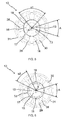
- the profile of the stator 14 of the electric motor 12 corresponds to the section, in other words to the geometric shape, of the stator 14 defined by a sectional plane VV orthogonal to the axis of rotation X of the stator 14, such as those of the Figures 5 and 6 .
- An electric motor stator 14 having a profile common to a range of actuators 11 may have a different stator length 14 depending on the motors.
- the length of the stator 14 is in no way limiting.
- the stator 14 can thus be of identical or different length, for each of the actuators 11 of a range.
- first rotor 13 and the second rotor 13 are internal rotors, that is to say rotors 13 disposed within the stator 14 having a common multi-purpose profile.
- first rotor 13 and the second rotor 13 are non-wound rotors.
- the coils 29 are positioned around the pole elements 28 of the stator 14 having a common multipurpose profile.
- An electric motor stator 14 having a profile common to a range of actuators 11 may have coils 29 having a different number of turns for each actuator.
- the number of turns of the coils 29 is in no way limiting.
- the coils 29 may thus comprise a number of turns, identical or different for each of the actuators 11 of a range.
- the stator 14 of the motor 12 is a multipurpose common stator, the stator 14 being configured to cooperate at least with a first rotor 13 so as to deliver a first torque value and with a second rotor 13 so as to output a second torque value, wherein the first torque value is less than the second torque value.
- an actuator 11 comprises an electric motor 12 provided with a common multipurpose stator 14 and configured to cooperate on the one hand with a first rotor 13 so as to deliver a first torque value and on the other hand with a second rotor 13 so as to deliver a second torque value.
- a first and a second actuator 11 respectively comprise an electric motor 12 provided with the same stator 14 so that a manufacturer can produce at least two different electric motors 12 comprising an identical stator 14, and where each electric motor 12 delivers a different couple.
- the coils 29 positioned around the pole elements 28 of the stator 14 may be identical for a range of actuators 11.
- the length of the stator 14 is identical for a range of actuators 11.
- At least a portion of the rotor body 15 of the first rotor 13 and at least a portion of the rotor body 15 of the second rotor 13 are made of a different material.
- the change of material for the rotor body 15 of the first and second rotors 13 makes it possible to modify the torque value delivered by an electric motor 12, so as to reduce the cost of the various references of actuators 11 by using a stator 14. having a common multipurpose profile.
- the change of material for the rotor body 15 of the first and second rotors 13 can make it possible to optimize the cost of an electric motor 12 by using a more or less expensive material making it possible to obtain a desired torque value. for an actuator reference 11.
- the change of material for the rotor body 15 of the first and second types of rotors 13 can supply a manufacturer of actuators in the event that one of the materials is broken.
- the rotor body 15 of the first rotor 13 comprises magnetic elements 16 made of ferrite
- the rotor body 15 of the second rotor 13 comprises magnetic elements 16 made of neodymium boron iron.
- a first actuator 11 as illustrated in FIG. figure 5 , comprising a first electric motor 12, wherein the first electric motor 12 comprises a first stator 14 having a common multi-purpose profile and a first rotor 13, and wherein the rotor body 15 of the first rotor 13 comprises ferrite magnetic elements 16 , delivers a weak couple.
- a second actuator 11, as illustrated in FIG. figure 6 comprising a second electric motor 12, wherein the second electric motor 12 comprises a second stator 14 having the common multipurpose profile and a second rotor 13, and wherein the rotor body 15 of the second rotor 13 comprises neodymium magnetic elements 16 iron boron, delivers a strong couple.
- a range of actuators 11 comprising electric motors 12 provided respectively with a stator 14 having a common multipurpose profile makes it possible to propose different torque values for each of the actuators 11 while minimizing the cost of obtaining them.
- the second actuator 11 may be of identical length to the first actuator 11 and can deliver a higher torque, and possibly achieve a better performance.
- the stator 14 having a common multipurpose profile comprises an arrangement of the pole elements 28 configured to cooperate with the first rotor 13 and with the second rotor 13.
- stator 14 having a common multipurpose profile makes it possible to produce at least two electric motors 12, where each electric motor 12 is differentiated by the delivered torque, by means of a single arrangement of the polar elements 28 to guarantee operation satisfactory of each of the electric motors 12 differentiated by the rotor 13 associated with this stator 14.
- pole members 28 of the stator 14 having a common multipurpose profile are dimensioned so as to guarantee satisfactory operation for all the motors 12 of the range using the same stator profile 14.
- the dimensioning of the polar elements 28 of the stator 14 having a common multipurpose profile consists in defining the width of the angular polar aperture A of each polar element 28 near the air gap 25. This dimensioning of the polar elements 28 of the stator 14 having a common multipurpose profile also consists in defining the number of polar elements 28.
- At least one parameter relating to the magnetic elements 16 of the first rotor 13 and the second rotor 13 is different.
- At least one parameter relating to the magnetic elements 16 of each of the rotors 13 is adapted as a function of the electric motor 12, so as to guarantee satisfactory operation for all the motors 12 of the range using the same stator profile 14.
- This at least one parameter may be in particular the material of the magnetic elements 16 of each of the rotors 13, the number of magnetic elements 16 of each of the rotors 13, the size of the magnetic elements 16 of each of the rotors 13 or the assembly method magnetic elements 16 with the rotor body 15 of each of the rotors 13.
- the number of pairs of poles of the first rotor 13 is smaller than the number of pairs of poles of the second rotor 13.
- the number of pairs of poles of each of the rotors 13 is adapted as a function of the electric motor 12, so as to to guarantee satisfactory operation for all the motors 12 of the range using a stator 14 having a common multipurpose profile.
- the number of pairs of poles of each of the rotors 13 is adapted according to the material of the magnetic elements 16. In this way, in the case where the magnetic elements 16 are powerful because of their material, in particular the elements In the case of ferrite magnets 16, the number of pole pairs of the rotor 13 is increased so as to use the stator 14 having a common multipurpose profile, without having to make modifications to this profile. .
- the size of the magnetic elements 16 of the first rotor 13 is greater than the size of the magnetic elements 16 of the second rotor 13.
- the size of the magnetic elements 16 is reduced, so as to use the stator 14 having the common multi-purpose profile, without having to make changes to this profile.
- the number of pairs of poles of the rotor 13 is defined so as to guarantee the generation of a magnetic flux by the electric motor 12 making it possible to saturate the magnetic short circuits 18 of the stator core 17.
- two electric motors 12 of actuators 11 belonging to a range comprising a stator 14 having a common multipurpose profile are defined by the following relationships: Br ⁇ 2 p ⁇ 2 + 1 ⁇ Br ⁇ 1 p ⁇ 1 ⁇ Br ⁇ 2 p ⁇ 2 where Br1 corresponds to the magnetic field of the magnetic elements 16 of a first rotor 13 of a first electric motor 12, Br2 corresponds to the magnetic field of the magnetic elements 16 of a second rotor 13 of a second electric motor 12, p1 to the number pairs of poles of the first rotor 13 of the first electric motor 12, and p2 the number of pairs of poles of the second rotor 13 of the second electric motor 12; and AT ⁇ 360 ⁇ ° 4 ⁇ p ⁇ 2 where A is the width of the polar angular aperture.
- Relation 1 makes it possible to guarantee satisfactory operation for all the motors 12 of the range using a stator 14 having a common multipurpose profile, in particular to maintain a suitable magnetic flux density, by the use of a number of whole pole pairs for the first and second rotors 13.
- the relation 2 makes it possible to determine an angular polar opening width A smaller than the narrowest angular width ⁇ 1, ⁇ 2 of the magnetic elements 16 of the first and second rotors 13.
- the range of electric motors 12 that can be implemented with a stator 14 having a common multipurpose profile may comprise a first electric motor 12 comprising a first rotor 13 provided with four ferrite magnetic elements 16, therefore two pairs of poles, and a second electric motor 12 comprising a second rotor 13 provided with eight magnetic elements 16 neodymium boron iron, therefore four pairs of poles.
- the magnetic field of the magnetic elements 16 of the first rotor 13 of the first electric motor 12 is of the order of 0.5 Tesla.
- the magnetic field of the magnetic elements 16 of the second rotor 13 of the second electric motor 12 is of the order of 1 Tesla.
- stator 14 having a common common profile multiple cooperating with the first and second rotors 13 comprises a number of polar elements 28 equal to six.
- the optimum angular polar opening width A for the first rotor 13 provided with four ferrite magnetic elements 16 is in a range between 30 ° and 55 °, and preferably of the order of 50 °.
- the optimum angular polar opening width A for the second rotor 13 provided with eight magnetic elements 16 in neodymium boron iron is in a range between 20 ° and 30 °, and preferably of the order of 25 °.
- the permissible operating range of the angular polar opening width A for a stator 14 having a common multipurpose profile with the first and second rotors 13 is between 20 ° and 40 °.
- Such an angular polar opening width A thus generates a loss of a portion of the magnetic flux generated by the magnetic circuit of the first electric motor 12 comprising the first rotor 13 provided with four ferrite magnetic elements 16.
- an angular polar opening width A of the polar elements 28 of the order of 45 ° can not be retained during the definition of the stator 14 having a common multi-purpose profile since the second rotor 13 provided with eight magnetic elements 16 in neodymium iron boron would be non-functional if such a value were retained.
- a stator 14 having a common multipurpose profile is assembled with either a first rotor 13 or with a second rotor 13 depending on the torque value that the motor Electric 12 to produce must deliver.
- stator profile 14 for a range of actuators 11 makes it possible to meet the need for applications requiring different motors that can deliver different torque values, in particular for motorization applications of flaps or doors of size and / or different weights.
Landscapes
- Engineering & Computer Science (AREA)
- Power Engineering (AREA)
- Manufacturing & Machinery (AREA)
- Iron Core Of Rotating Electric Machines (AREA)
- Connection Of Motors, Electrical Generators, Mechanical Devices, And The Like (AREA)
Priority Applications (1)
| Application Number | Priority Date | Filing Date | Title |
|---|---|---|---|
| PL15155163T PL2908412T3 (pl) | 2014-02-17 | 2015-02-16 | Siłownik elektromechaniczny zawierający silnik elektryczny, instalacja zawierająca taki siłownik, zakres siłowników i powiązany sposób wytwarzania |
Applications Claiming Priority (1)
| Application Number | Priority Date | Filing Date | Title |
|---|---|---|---|
| FR1451245A FR3017753B1 (fr) | 2014-02-17 | 2014-02-17 | Actionneur electromecanique comprenant un moteur electrique, installation comprenant un tel actionneur, gamme d'actionneurs et procede de fabrication associe |
Publications (3)
| Publication Number | Publication Date |
|---|---|
| EP2908412A2 true EP2908412A2 (de) | 2015-08-19 |
| EP2908412A3 EP2908412A3 (de) | 2016-06-15 |
| EP2908412B1 EP2908412B1 (de) | 2020-03-18 |
Family
ID=50976805
Family Applications (1)
| Application Number | Title | Priority Date | Filing Date |
|---|---|---|---|
| EP15155163.7A Active EP2908412B1 (de) | 2014-02-17 | 2015-02-16 | Elektromechanisches Stellglied, das einen Elektromotor umfasst, Anlage, die ein solches Stellglied umfasst, Auswahlpalette an Stellgliedern und entsprechendes Herstellungsverfahren |
Country Status (4)
| Country | Link |
|---|---|
| EP (1) | EP2908412B1 (de) |
| CN (1) | CN104852483A (de) |
| FR (1) | FR3017753B1 (de) |
| PL (1) | PL2908412T3 (de) |
Cited By (3)
| Publication number | Priority date | Publication date | Assignee | Title |
|---|---|---|---|---|
| CN105450097A (zh) * | 2016-01-07 | 2016-03-30 | 湖州鸿远电机有限公司 | 一种卷帘门无刷电机驱动装置 |
| CN105450102A (zh) * | 2016-01-07 | 2016-03-30 | 湖州鸿远电机有限公司 | 一种自动卷帘门控制系统 |
| CN105515462A (zh) * | 2016-01-07 | 2016-04-20 | 湖州鸿远电机有限公司 | 一种自动卷帘门系统 |
Families Citing this family (3)
| Publication number | Priority date | Publication date | Assignee | Title |
|---|---|---|---|---|
| GB201515845D0 (en) * | 2015-09-07 | 2015-10-21 | Trw Ltd | An electromechanical actuator |
| GB201515843D0 (en) * | 2015-09-07 | 2015-10-21 | Trw Ltd | An electromechanical actuator |
| CA3208813A1 (en) | 2021-01-19 | 2022-07-28 | Gates Corporation | Axial flux motor having a mechanically independent stator |
Citations (4)
| Publication number | Priority date | Publication date | Assignee | Title |
|---|---|---|---|---|
| US6531794B1 (en) | 2000-07-20 | 2003-03-11 | General Electric Company | Method for fabricating motors of different outputs using standardized parts |
| US20060273684A1 (en) | 2005-06-01 | 2006-12-07 | Denso Corporation | Multi-phase brushless motor with reduced number of stator poles |
| JP2007174790A (ja) | 2005-12-21 | 2007-07-05 | Kokusan Denki Co Ltd | 電動機用回転子 |
| US20090127960A1 (en) | 2007-11-12 | 2009-05-21 | Kiyomi Kawamura | Anisotropic permanent magnet motor |
Family Cites Families (6)
| Publication number | Priority date | Publication date | Assignee | Title |
|---|---|---|---|---|
| JP2930556B2 (ja) * | 1997-01-16 | 1999-08-03 | ファナック株式会社 | 同期電動機の機種拡張方法及び該拡張方法により製造される同期電動機 |
| JP2005080381A (ja) * | 2003-08-29 | 2005-03-24 | Mitsubishi Heavy Ind Ltd | Ipm回転電機 |
| FR2945388B1 (fr) * | 2009-05-11 | 2013-04-12 | Moving Magnet Technologies M M T | Moteur electrique triphase a faible couple de detente |
| DE102009056647A1 (de) * | 2009-12-02 | 2011-06-09 | Brose Fahrzeugteile GmbH & Co. Kommanditgesellschaft, Würzburg | Stator für einen Elektromotor sowie Verfahren zu dessen Herstellung |
| JP2011130605A (ja) * | 2009-12-18 | 2011-06-30 | Minebea Co Ltd | ブラシレスモータ |
| US9231459B2 (en) * | 2011-05-06 | 2016-01-05 | Qm Power, Inc. | Motor topology with exchangeable components to form different classes of motors |
-
2014
- 2014-02-17 FR FR1451245A patent/FR3017753B1/fr active Active
-
2015
- 2015-02-16 PL PL15155163T patent/PL2908412T3/pl unknown
- 2015-02-16 EP EP15155163.7A patent/EP2908412B1/de active Active
- 2015-02-17 CN CN201510085328.2A patent/CN104852483A/zh active Pending
Patent Citations (4)
| Publication number | Priority date | Publication date | Assignee | Title |
|---|---|---|---|---|
| US6531794B1 (en) | 2000-07-20 | 2003-03-11 | General Electric Company | Method for fabricating motors of different outputs using standardized parts |
| US20060273684A1 (en) | 2005-06-01 | 2006-12-07 | Denso Corporation | Multi-phase brushless motor with reduced number of stator poles |
| JP2007174790A (ja) | 2005-12-21 | 2007-07-05 | Kokusan Denki Co Ltd | 電動機用回転子 |
| US20090127960A1 (en) | 2007-11-12 | 2009-05-21 | Kiyomi Kawamura | Anisotropic permanent magnet motor |
Cited By (3)
| Publication number | Priority date | Publication date | Assignee | Title |
|---|---|---|---|---|
| CN105450097A (zh) * | 2016-01-07 | 2016-03-30 | 湖州鸿远电机有限公司 | 一种卷帘门无刷电机驱动装置 |
| CN105450102A (zh) * | 2016-01-07 | 2016-03-30 | 湖州鸿远电机有限公司 | 一种自动卷帘门控制系统 |
| CN105515462A (zh) * | 2016-01-07 | 2016-04-20 | 湖州鸿远电机有限公司 | 一种自动卷帘门系统 |
Also Published As
| Publication number | Publication date |
|---|---|
| FR3017753A1 (fr) | 2015-08-21 |
| FR3017753B1 (fr) | 2017-08-25 |
| EP2908412A3 (de) | 2016-06-15 |
| CN104852483A (zh) | 2015-08-19 |
| PL2908412T3 (pl) | 2020-09-07 |
| EP2908412B1 (de) | 2020-03-18 |
Similar Documents
| Publication | Publication Date | Title |
|---|---|---|
| EP2908412B1 (de) | Elektromechanisches Stellglied, das einen Elektromotor umfasst, Anlage, die ein solches Stellglied umfasst, Auswahlpalette an Stellgliedern und entsprechendes Herstellungsverfahren | |
| EP3440764B1 (de) | Elektromechanischer aktuator zur steuerung von abschirmungen und heimautomatisierungsausrüstung mit solch einem aktuator | |
| EP3283721B1 (de) | Motorisierte antriebsvorrichtung für eine schliess- oder sonnenschutz-heimautomatisierungsanlage, zugehörige heimautomatisierungsanlage und verfahren zur steuerung des betriebs solch einer vorrichtung | |
| EP2922183B1 (de) | Elektromechanisches Betätigungselement, zugeordnet Domotik-Installation und Herstellungsverfahren. | |
| EP4082156B1 (de) | Elektromechanischer aktuator zum antrieb eines verschlusses oder sonnenschutzschirmes, verschluss- oder sonnenschutzsystem mit einem solchen aktuator und verfahren zur dimensionierung einer kompensationsfeder für eine reihe von jalousien mit je einem solchen aktuator | |
| EP3870796A1 (de) | Elektromechanischer aktuator und heimautomatisierungsanlage mit einem solchen aktuator | |
| EP3209845B1 (de) | Spektrum an vorrichtungen mit motorisiertem antrieb für jalousien | |
| EP3440765B1 (de) | Elektromechanischer aktuator zur steuerung von anzeigebildschirmen, hausautomatisiserungssystem mit diesem aktuator und satz aus mindestens zwei dieser aktuatoren | |
| WO2023247867A1 (fr) | Actionneur electromagnetique comprenant un moteur synchrone compact et silencieux avec des aimants permanents encastrés | |
| FR2801146A1 (fr) | Actionneur de vanne de climatisation d'air pour vehicule automobile | |
| EP4544664A1 (de) | Elektromechanischer aktuator mit einem kompakten und geräuscharmen synchronreluktanzmotor | |
| EP3017525B1 (de) | Anordnung eines elektrischen stellantriebs und verfahren zum herstellen eines motors eines zu einer solchen anordnung gehöhrenden stellantriebs. | |
| EP3139487B1 (de) | Bremssystem und -methode eines elektromotors | |
| EP4020777B1 (de) | Rotor für einen elektromotor, elektromotor mit einem solchen rotor und herstellungsverfahren eines solchen rotors | |
| WO2024141726A1 (fr) | Dispositif et procédé de contrôle d'un moteur électrique prenant en compte un environnement mécanique du moteur | |
| WO2024141725A1 (fr) | Dispositif et procede de controle d'un moteur electrique avec une loi de commande de type pas a pas | |
| FR3055486A1 (fr) | Rotor pour un moteur electrique, moteur electrique comprenant un tel rotor et procede de fabrication d'un tel rotor | |
| EP4576463A1 (de) | Stromversorgungsvorrichtung, motorisierte antriebsvorrichtung mit solch einer stromversorgungsvorrichtung und verdunkelungsvorrichtung dafür | |
| WO2023111415A1 (fr) | Dispositif et procédé de contrôle d'un moteur électrique en vue de réduire un bruit de fonctionnement | |
| FR3139592A1 (fr) | Dispositif d’entraînement motorisé d’un dispositif d’occultation et dispositif d’occultation associé |
Legal Events
| Date | Code | Title | Description |
|---|---|---|---|
| PUAI | Public reference made under article 153(3) epc to a published international application that has entered the european phase |
Free format text: ORIGINAL CODE: 0009012 |
|
| AK | Designated contracting states |
Kind code of ref document: A2 Designated state(s): AL AT BE BG CH CY CZ DE DK EE ES FI FR GB GR HR HU IE IS IT LI LT LU LV MC MK MT NL NO PL PT RO RS SE SI SK SM TR |
|
| AX | Request for extension of the european patent |
Extension state: BA ME |
|
| PUAL | Search report despatched |
Free format text: ORIGINAL CODE: 0009013 |
|
| AK | Designated contracting states |
Kind code of ref document: A3 Designated state(s): AL AT BE BG CH CY CZ DE DK EE ES FI FR GB GR HR HU IE IS IT LI LT LU LV MC MK MT NL NO PL PT RO RS SE SI SK SM TR |
|
| AX | Request for extension of the european patent |
Extension state: BA ME |
|
| RIC1 | Information provided on ipc code assigned before grant |
Ipc: H02K 15/00 20060101AFI20160512BHEP Ipc: H02K 15/03 20060101ALN20160512BHEP Ipc: H02K 21/16 20060101ALN20160512BHEP |
|
| STAA | Information on the status of an ep patent application or granted ep patent |
Free format text: STATUS: REQUEST FOR EXAMINATION WAS MADE |
|
| 17P | Request for examination filed |
Effective date: 20161201 |
|
| RBV | Designated contracting states (corrected) |
Designated state(s): AL AT BE BG CH CY CZ DE DK EE ES FI FR GB GR HR HU IE IS IT LI LT LU LV MC MK MT NL NO PL PT RO RS SE SI SK SM TR |
|
| STAA | Information on the status of an ep patent application or granted ep patent |
Free format text: STATUS: EXAMINATION IS IN PROGRESS |
|
| 17Q | First examination report despatched |
Effective date: 20170503 |
|
| GRAP | Despatch of communication of intention to grant a patent |
Free format text: ORIGINAL CODE: EPIDOSNIGR1 |
|
| STAA | Information on the status of an ep patent application or granted ep patent |
Free format text: STATUS: GRANT OF PATENT IS INTENDED |
|
| RIC1 | Information provided on ipc code assigned before grant |
Ipc: H02K 15/00 20060101AFI20191001BHEP Ipc: H02K 15/03 20060101ALN20191001BHEP Ipc: H02K 21/16 20060101ALN20191001BHEP |
|
| INTG | Intention to grant announced |
Effective date: 20191024 |
|
| RAP1 | Party data changed (applicant data changed or rights of an application transferred) |
Owner name: SOMFY ACTIVITES SA |
|
| GRAS | Grant fee paid |
Free format text: ORIGINAL CODE: EPIDOSNIGR3 |
|
| GRAA | (expected) grant |
Free format text: ORIGINAL CODE: 0009210 |
|
| STAA | Information on the status of an ep patent application or granted ep patent |
Free format text: STATUS: THE PATENT HAS BEEN GRANTED |
|
| AK | Designated contracting states |
Kind code of ref document: B1 Designated state(s): AL AT BE BG CH CY CZ DE DK EE ES FI FR GB GR HR HU IE IS IT LI LT LU LV MC MK MT NL NO PL PT RO RS SE SI SK SM TR |
|
| REG | Reference to a national code |
Ref country code: GB Ref legal event code: FG4D Free format text: NOT ENGLISH |
|
| REG | Reference to a national code |
Ref country code: DE Ref legal event code: R096 Ref document number: 602015048868 Country of ref document: DE |
|
| REG | Reference to a national code |
Ref country code: AT Ref legal event code: REF Ref document number: 1247067 Country of ref document: AT Kind code of ref document: T Effective date: 20200415 Ref country code: IE Ref legal event code: FG4D Free format text: LANGUAGE OF EP DOCUMENT: FRENCH |
|
| PG25 | Lapsed in a contracting state [announced via postgrant information from national office to epo] |
Ref country code: RS Free format text: LAPSE BECAUSE OF FAILURE TO SUBMIT A TRANSLATION OF THE DESCRIPTION OR TO PAY THE FEE WITHIN THE PRESCRIBED TIME-LIMIT Effective date: 20200318 Ref country code: FI Free format text: LAPSE BECAUSE OF FAILURE TO SUBMIT A TRANSLATION OF THE DESCRIPTION OR TO PAY THE FEE WITHIN THE PRESCRIBED TIME-LIMIT Effective date: 20200318 Ref country code: NO Free format text: LAPSE BECAUSE OF FAILURE TO SUBMIT A TRANSLATION OF THE DESCRIPTION OR TO PAY THE FEE WITHIN THE PRESCRIBED TIME-LIMIT Effective date: 20200618 |
|
| REG | Reference to a national code |
Ref country code: NL Ref legal event code: MP Effective date: 20200318 |
|
| PG25 | Lapsed in a contracting state [announced via postgrant information from national office to epo] |
Ref country code: BG Free format text: LAPSE BECAUSE OF FAILURE TO SUBMIT A TRANSLATION OF THE DESCRIPTION OR TO PAY THE FEE WITHIN THE PRESCRIBED TIME-LIMIT Effective date: 20200618 Ref country code: HR Free format text: LAPSE BECAUSE OF FAILURE TO SUBMIT A TRANSLATION OF THE DESCRIPTION OR TO PAY THE FEE WITHIN THE PRESCRIBED TIME-LIMIT Effective date: 20200318 Ref country code: GR Free format text: LAPSE BECAUSE OF FAILURE TO SUBMIT A TRANSLATION OF THE DESCRIPTION OR TO PAY THE FEE WITHIN THE PRESCRIBED TIME-LIMIT Effective date: 20200619 Ref country code: LV Free format text: LAPSE BECAUSE OF FAILURE TO SUBMIT A TRANSLATION OF THE DESCRIPTION OR TO PAY THE FEE WITHIN THE PRESCRIBED TIME-LIMIT Effective date: 20200318 Ref country code: SE Free format text: LAPSE BECAUSE OF FAILURE TO SUBMIT A TRANSLATION OF THE DESCRIPTION OR TO PAY THE FEE WITHIN THE PRESCRIBED TIME-LIMIT Effective date: 20200318 |
|
| REG | Reference to a national code |
Ref country code: LT Ref legal event code: MG4D |
|
| PG25 | Lapsed in a contracting state [announced via postgrant information from national office to epo] |
Ref country code: NL Free format text: LAPSE BECAUSE OF FAILURE TO SUBMIT A TRANSLATION OF THE DESCRIPTION OR TO PAY THE FEE WITHIN THE PRESCRIBED TIME-LIMIT Effective date: 20200318 |
|
| PG25 | Lapsed in a contracting state [announced via postgrant information from national office to epo] |
Ref country code: IS Free format text: LAPSE BECAUSE OF FAILURE TO SUBMIT A TRANSLATION OF THE DESCRIPTION OR TO PAY THE FEE WITHIN THE PRESCRIBED TIME-LIMIT Effective date: 20200718 Ref country code: SK Free format text: LAPSE BECAUSE OF FAILURE TO SUBMIT A TRANSLATION OF THE DESCRIPTION OR TO PAY THE FEE WITHIN THE PRESCRIBED TIME-LIMIT Effective date: 20200318 Ref country code: SM Free format text: LAPSE BECAUSE OF FAILURE TO SUBMIT A TRANSLATION OF THE DESCRIPTION OR TO PAY THE FEE WITHIN THE PRESCRIBED TIME-LIMIT Effective date: 20200318 Ref country code: PT Free format text: LAPSE BECAUSE OF FAILURE TO SUBMIT A TRANSLATION OF THE DESCRIPTION OR TO PAY THE FEE WITHIN THE PRESCRIBED TIME-LIMIT Effective date: 20200812 Ref country code: LT Free format text: LAPSE BECAUSE OF FAILURE TO SUBMIT A TRANSLATION OF THE DESCRIPTION OR TO PAY THE FEE WITHIN THE PRESCRIBED TIME-LIMIT Effective date: 20200318 Ref country code: EE Free format text: LAPSE BECAUSE OF FAILURE TO SUBMIT A TRANSLATION OF THE DESCRIPTION OR TO PAY THE FEE WITHIN THE PRESCRIBED TIME-LIMIT Effective date: 20200318 Ref country code: CZ Free format text: LAPSE BECAUSE OF FAILURE TO SUBMIT A TRANSLATION OF THE DESCRIPTION OR TO PAY THE FEE WITHIN THE PRESCRIBED TIME-LIMIT Effective date: 20200318 Ref country code: RO Free format text: LAPSE BECAUSE OF FAILURE TO SUBMIT A TRANSLATION OF THE DESCRIPTION OR TO PAY THE FEE WITHIN THE PRESCRIBED TIME-LIMIT Effective date: 20200318 |
|
| REG | Reference to a national code |
Ref country code: AT Ref legal event code: MK05 Ref document number: 1247067 Country of ref document: AT Kind code of ref document: T Effective date: 20200318 |
|
| REG | Reference to a national code |
Ref country code: DE Ref legal event code: R097 Ref document number: 602015048868 Country of ref document: DE |
|
| PLBE | No opposition filed within time limit |
Free format text: ORIGINAL CODE: 0009261 |
|
| STAA | Information on the status of an ep patent application or granted ep patent |
Free format text: STATUS: NO OPPOSITION FILED WITHIN TIME LIMIT |
|
| PG25 | Lapsed in a contracting state [announced via postgrant information from national office to epo] |
Ref country code: DK Free format text: LAPSE BECAUSE OF FAILURE TO SUBMIT A TRANSLATION OF THE DESCRIPTION OR TO PAY THE FEE WITHIN THE PRESCRIBED TIME-LIMIT Effective date: 20200318 Ref country code: IT Free format text: LAPSE BECAUSE OF FAILURE TO SUBMIT A TRANSLATION OF THE DESCRIPTION OR TO PAY THE FEE WITHIN THE PRESCRIBED TIME-LIMIT Effective date: 20200318 Ref country code: ES Free format text: LAPSE BECAUSE OF FAILURE TO SUBMIT A TRANSLATION OF THE DESCRIPTION OR TO PAY THE FEE WITHIN THE PRESCRIBED TIME-LIMIT Effective date: 20200318 Ref country code: AT Free format text: LAPSE BECAUSE OF FAILURE TO SUBMIT A TRANSLATION OF THE DESCRIPTION OR TO PAY THE FEE WITHIN THE PRESCRIBED TIME-LIMIT Effective date: 20200318 |
|
| 26N | No opposition filed |
Effective date: 20201221 |
|
| PG25 | Lapsed in a contracting state [announced via postgrant information from national office to epo] |
Ref country code: SI Free format text: LAPSE BECAUSE OF FAILURE TO SUBMIT A TRANSLATION OF THE DESCRIPTION OR TO PAY THE FEE WITHIN THE PRESCRIBED TIME-LIMIT Effective date: 20200318 |
|
| PG25 | Lapsed in a contracting state [announced via postgrant information from national office to epo] |
Ref country code: MC Free format text: LAPSE BECAUSE OF FAILURE TO SUBMIT A TRANSLATION OF THE DESCRIPTION OR TO PAY THE FEE WITHIN THE PRESCRIBED TIME-LIMIT Effective date: 20200318 |
|
| GBPC | Gb: european patent ceased through non-payment of renewal fee |
Effective date: 20210216 |
|
| REG | Reference to a national code |
Ref country code: BE Ref legal event code: MM Effective date: 20210228 |
|
| PG25 | Lapsed in a contracting state [announced via postgrant information from national office to epo] |
Ref country code: CH Free format text: LAPSE BECAUSE OF NON-PAYMENT OF DUE FEES Effective date: 20210228 Ref country code: LU Free format text: LAPSE BECAUSE OF NON-PAYMENT OF DUE FEES Effective date: 20210216 Ref country code: LI Free format text: LAPSE BECAUSE OF NON-PAYMENT OF DUE FEES Effective date: 20210228 |
|
| PG25 | Lapsed in a contracting state [announced via postgrant information from national office to epo] |
Ref country code: IE Free format text: LAPSE BECAUSE OF NON-PAYMENT OF DUE FEES Effective date: 20210216 Ref country code: GB Free format text: LAPSE BECAUSE OF NON-PAYMENT OF DUE FEES Effective date: 20210216 |
|
| PG25 | Lapsed in a contracting state [announced via postgrant information from national office to epo] |
Ref country code: BE Free format text: LAPSE BECAUSE OF NON-PAYMENT OF DUE FEES Effective date: 20210228 |
|
| PG25 | Lapsed in a contracting state [announced via postgrant information from national office to epo] |
Ref country code: HU Free format text: LAPSE BECAUSE OF FAILURE TO SUBMIT A TRANSLATION OF THE DESCRIPTION OR TO PAY THE FEE WITHIN THE PRESCRIBED TIME-LIMIT; INVALID AB INITIO Effective date: 20150216 |
|
| PG25 | Lapsed in a contracting state [announced via postgrant information from national office to epo] |
Ref country code: CY Free format text: LAPSE BECAUSE OF FAILURE TO SUBMIT A TRANSLATION OF THE DESCRIPTION OR TO PAY THE FEE WITHIN THE PRESCRIBED TIME-LIMIT Effective date: 20200318 |
|
| PG25 | Lapsed in a contracting state [announced via postgrant information from national office to epo] |
Ref country code: MK Free format text: LAPSE BECAUSE OF FAILURE TO SUBMIT A TRANSLATION OF THE DESCRIPTION OR TO PAY THE FEE WITHIN THE PRESCRIBED TIME-LIMIT Effective date: 20200318 |
|
| PG25 | Lapsed in a contracting state [announced via postgrant information from national office to epo] |
Ref country code: MT Free format text: LAPSE BECAUSE OF FAILURE TO SUBMIT A TRANSLATION OF THE DESCRIPTION OR TO PAY THE FEE WITHIN THE PRESCRIBED TIME-LIMIT Effective date: 20200318 |
|
| PG25 | Lapsed in a contracting state [announced via postgrant information from national office to epo] |
Ref country code: TR Free format text: LAPSE BECAUSE OF FAILURE TO SUBMIT A TRANSLATION OF THE DESCRIPTION OR TO PAY THE FEE WITHIN THE PRESCRIBED TIME-LIMIT Effective date: 20200318 |
|
| PGFP | Annual fee paid to national office [announced via postgrant information from national office to epo] |
Ref country code: FR Payment date: 20251219 Year of fee payment: 12 |
|
| PGFP | Annual fee paid to national office [announced via postgrant information from national office to epo] |
Ref country code: DE Payment date: 20260206 Year of fee payment: 12 |
|
| PGFP | Annual fee paid to national office [announced via postgrant information from national office to epo] |
Ref country code: PL Payment date: 20260119 Year of fee payment: 12 |