EP2908407B1 - Elektrischer Antriebsmotor, Pumpe und Haushaltsgerät mit einer solchen Pumpe - Google Patents
Elektrischer Antriebsmotor, Pumpe und Haushaltsgerät mit einer solchen Pumpe Download PDFInfo
- Publication number
- EP2908407B1 EP2908407B1 EP15153872.5A EP15153872A EP2908407B1 EP 2908407 B1 EP2908407 B1 EP 2908407B1 EP 15153872 A EP15153872 A EP 15153872A EP 2908407 B1 EP2908407 B1 EP 2908407B1
- Authority
- EP
- European Patent Office
- Prior art keywords
- drive motor
- electric drive
- end wall
- permanent magnet
- side wall
- Prior art date
- Legal status (The legal status is an assumption and is not a legal conclusion. Google has not performed a legal analysis and makes no representation as to the accuracy of the status listed.)
- Active
Links
Images

Classifications
-
- H—ELECTRICITY
- H02—GENERATION; CONVERSION OR DISTRIBUTION OF ELECTRIC POWER
- H02K—DYNAMO-ELECTRIC MACHINES
- H02K1/00—Details of the magnetic circuit
- H02K1/06—Details of the magnetic circuit characterised by the shape, form or construction
- H02K1/22—Rotating parts of the magnetic circuit
- H02K1/27—Rotor cores with permanent magnets
- H02K1/2706—Inner rotors
- H02K1/272—Inner rotors the magnetisation axis of the magnets being perpendicular to the rotor axis
- H02K1/274—Inner rotors the magnetisation axis of the magnets being perpendicular to the rotor axis the rotor consisting of two or more circumferentially positioned magnets
- H02K1/2753—Inner rotors the magnetisation axis of the magnets being perpendicular to the rotor axis the rotor consisting of two or more circumferentially positioned magnets the rotor consisting of magnets or groups of magnets arranged with alternating polarity
- H02K1/278—Surface mounted magnets; Inset magnets
-
- H—ELECTRICITY
- H02—GENERATION; CONVERSION OR DISTRIBUTION OF ELECTRIC POWER
- H02K—DYNAMO-ELECTRIC MACHINES
- H02K5/00—Casings; Enclosures; Supports
- H02K5/04—Casings or enclosures characterised by the shape, form or construction thereof
- H02K5/12—Casings or enclosures characterised by the shape, form or construction thereof specially adapted for operating in liquid or gas
- H02K5/128—Casings or enclosures characterised by the shape, form or construction thereof specially adapted for operating in liquid or gas using air-gap sleeves or air-gap discs
-
- H—ELECTRICITY
- H02—GENERATION; CONVERSION OR DISTRIBUTION OF ELECTRIC POWER
- H02K—DYNAMO-ELECTRIC MACHINES
- H02K15/00—Processes or apparatus specially adapted for manufacturing, assembling, maintaining or repairing of dynamo-electric machines
- H02K15/12—Impregnating, moulding insulation, heating or drying of windings, stators, rotors or machines
-
- H—ELECTRICITY
- H02—GENERATION; CONVERSION OR DISTRIBUTION OF ELECTRIC POWER
- H02K—DYNAMO-ELECTRIC MACHINES
- H02K2213/00—Specific aspects, not otherwise provided for and not covered by codes H02K2201/00 - H02K2211/00
- H02K2213/03—Machines characterised by numerical values, ranges, mathematical expressions or similar information
Definitions
- the invention relates to an electric drive motor for a pump, comprising an electrically controllable stator winding and a rotor in the field of the stator winding while leaving an annular gap rotatably mounted rotor having a motor shaft, a seated on the motor shaft magnet carrier and a plurality of at least one circumferential surface of the magnet carrier distributed permanent magnets each having at least one outer surface and which are secured by means of a plastic body by encapsulating the magnetic carrier on the magnetic carrier, wherein the magnetic carrier has a polygonal cross-section, each permanent magnet pointing in the direction of the magnetic carrier planar base and an outer surface with a cylinder jacket segment-shaped shape has, wherein the permanent magnets on its the annular gap facing outer surface by the plastic body such a positive and / or non-positively held s ind that at least a part of these outer surfaces is exposed in the annular gap.
- the invention also relates to a pump with such a drive motor and a household appliance, in particular a dishwasher, washing machine or dryer, with such an electric drive motor and / or such a pump.
- An electric drive motor of the type mentioned is for example from the DE 84 27 707 U1 known.
- Magnetic segments are mounted on the outer circumference of a rotating support body of soft magnetic material in that plastic material is injected into slots of the support body and between the magnet segments. The magnet segments are thereby held on the support body by an anchored in the interior of the support body plastic cage.
- the WO 01/11756 A1 describes a brushless electric motor of a pump.
- the rotor of the motor consists of a laminated core, the surface of which has a substantially prismatic shape. Magnetic segments are arranged on the surfaces having substantially rectangular cross-sections and flat side surfaces. The magnet segments are thereby connected to the laminated core that they are completely covered by a plastic melt.
- the plastic melt forms a cylindrical body of the rotor, in which the magnet segments are completely embedded.
- the rotor of the US 2012/0313463 A1 has in cross-section in the interior as a magnetic yoke four "arcs of steel 109", ie four circular arc sections made of steel, which are each assembled with a remaining circumferential gap between each two circumferentially adjacent "arcs of steel” to a circular ring. On this outside four individual (viewed in cross-section) arcuate magnets are arranged.
- FIG. 1 of the JP 2002034188 A is viewed in cross-section a ferromagnetic yoke in the form of a circular ring provided. On this outside sit individual magnets, each having a circular arc section-shaped cross-sectional shape. They are fixed in position by a "resin 14" on the yoke.
- the individual magnets also formed as a circular arc section-like elements and held in the form of a magnet ring in a circular arc-shaped cage.
- the inner surfaces of the magnets are in contact with a metallic insert (section [0064]: "and the inner surfaces of the magnets are in contact with the metal insert 17").
- the magnets are each formed in cross-section arcuate portion-shaped and arranged on the outer circumference of a circular cylindrical core, which is designed as a laminated core "lamination packet" and serves as a magnetic inference for the magnetic fields of the magnets 10.
- the JP H01 286747 A relates to a motor of a recirculation pump in an atomic reactor.
- the iron material of the engine core contains only 0.4 to 2% chromium. This improves the corrosion resistance of the motor without losing its magnetic properties.
- the EP 1 967 288 A2 provides in the field of oil and gas industry a rotor shaft and stator assembly for example turboexpander, pumps, compressors, ... with magnetic bearings for supporting a circular cylindrical rotor shaft before.
- Their section indicates as material for the rotor shaft "a magnetic steel of type 17-4PH stainless steel alloy, a precipitation hardened martensitic stainless steel alloy" makes it clear, however, that this leads to magnetic losses.
- the object of the invention is to provide an electric drive motor for a pump, a pump with such an electric drive motor, and a household appliance with such an electric drive motor and / or such a pump, which is inexpensive and has an improved life and / or a having improved efficiency.
- an electric drive motor for a pump has an electrically controllable stator winding and a rotor rotatably mounted in the field of the stator winding while leaving an annular gap, which has a motor shaft, a magnet carrier seated on the motor shaft and a plurality of permanent magnets distributed around at least one lateral surface of the magnet carrier, each having at least one outer surface and which are fixed by means of a plastic body produced by encapsulation of the magnetic carrier on the magnetic carrier, wherein the magnetic carrier has a polygonal cross-section, each permanent magnet having a pointing in the direction of the magnetic carrier planar base and an outer surface with a cylinder jacket segment-shaped shape, and wherein the permanent magnets are held in such a form and / or non-positively by the plastic body at its outer surface facing the annular gap, that at least part of these outer surfaces is exposed in the annular gap.
- the magnetic carrier made of a ferentially by the plastic body at its outer surface facing the annular gap, that at least part of these outer surfaces is
- the magnetic carrier made of a ferromagnetic chrome steel may have a hexagonal cross-section.
- the plastic body may be formed as a plastic cage, the form-fitting and / or frictionally engages the respectively exposed part of the outer surface of each permanent magnet.
- each permanent magnet facing the annular gap is wetted by the liquid present in the annular gap.
- the outer surfaces of each permanent magnet facing the annular gap are surrounded by the air or gas present in the annular gap.
- the plastic cage formed by the encapsulation may have a peripheral surface, which complement with the outer surfaces of the permanent magnets, which face the annular gap, to form a cylindrical jacket wall, which forms an outer jacket wall of the rotor.
- the outer surfaces of the permanent magnets can so far flush with the peripheral surface of the plastic cage, in particular while lying on the same radius.
- the permanent magnets can be attached to the magnet carrier by means of a plastic cage designed as a plastic body, which encloses each permanent magnet in a form-fitting and / or non-positively locking manner, each freeing a part of the outer surfaces that points to the annular gap.
- each permanent magnet may have at least one chamfer, in particular at least one circumferential around its outer surface chamfer, of the Plastic body, in particular of the plastic cage is framed form and / or non-positively.
- the width of the annular gap is reduced as much as possible.
- the rotor is constructed such that the outer surfaces of the permanent magnets directly adjoin the annular gap.
- the distance between the outer surfaces of the permanent magnets can be significantly reduced to the stator winding, whereby the efficiency of the increased electric drive motor.
- each permanent magnet has an outer surface adjoining the annular gap, which is delimited by at least one bevel surrounding the outer surface and which is frictionally enclosed by the plastic cage, the largest possible surface area of the outer surface of the permanent magnets can directly adjoin the annular gap by the inventively around the outer surface at least one chamfer the permanent magnets are held by the plastic cage positively on the magnetic carrier, without the need for a separate steel pot or a permanent magnets completely enclosing plastic cage, whereby the permanent magnets would inevitably be arranged at a greater distance from the stator winding ,
- All permanent magnets of a rotor are preferably identical. In particular, they can be distributed at equal distances from one another over the circumference of the magnet carrier.
- the outer surfaces of the permanent magnets have a cylinder jacket segment-shaped shape.
- the distributed over the circumference of the magnetic carrier permanent magnets complement each other in their outer surfaces so far to a substantially cylindrical outer surface, which are interrupted only by slight webs of the plastic cage.
- each permanent magnet has at least one circumferential chamfer, which are arranged around the magnet carrier permanent magnets can be positively secured by the overmolded plastic cage on the magnet carrier such that the plastic cage together with the permanent magnet forms a smooth-walled cylindrical shell wall of the rotor, which forms windows be formed directly from the outer surfaces of the permanent magnets.
- each permanent magnet may include a front end wall, a rear end wall, a sidewall advancing in the direction of rotation of the rotor, and a trailing sidewall, wherein the at least one chamfer is formed by the front end wall, the rear end wall, the leading sidewall, and the trailing sidewall in each case from one to a pointing in the direction of the magnetic carrier surface of the permanent magnet perpendicular position beveled by an angle inwardly employed position.
- the front end wall of the permanent magnet is so far a side wall of the permanent magnet, which points in an installed position of the permanent magnet on the rotor in the direction of the front shaft end of the motor shaft, which end of the shaft carries in particular in the case of a pump impeller.
- the rear end wall of the permanent magnet is a side wall of the permanent magnet opposed to the front end wall, which faces away from the front shaft end of the motor shaft in an installed position of the permanent magnet on the rotor. With its base surface of the respective permanent magnet is applied to a lateral surface of the magnetic carrier in particular touching.
- the property that the front end wall, the rear end wall, the leading side wall and the trailing side wall are each bevelled beveled from a position perpendicular to a pointing in the direction of the magnetic carrier base surface of the permanent magnet position by an angle inwardly salaried position, in other words meaning different in that the permanent magnets have a truncated pyramidal shape, the larger base area of the truncated pyramid being formed by the base area of the permanent magnet and the smaller top area of the truncated pyramid being formed by the outer surface of the permanent magnet and in particular the perpendicular passing through the imaginary tip intersecting the base area.
- the base can be rectangular or square in particular.
- the height of the permanent magnet is smaller by a multiple than the length or width of the base.
- the angle that is, the angle of inclination of the side surfaces of the truncated pyramidal permanent magnet with respect to its base inwardly can be in a range of values of 1 to 20 degrees, in particular has a value of 8 degrees.
- the front end wall, the rear end wall, the leading sidewall and the trailing sidewall each directly connecting side edges to form a single, edgeless around the outer surface of the permanent magnet circumferential bevel are rounded.
- a single circumferential chamfer can be formed, which runs around the permanent magnet without corners.
- Such a chamfer can be made in a favorable manner, can reduce material stresses in the permanent magnet and favor a fixation by the overmolded plastic cage.
- At least one of the front end wall, the rear end wall, the leading sidewall and / or the trailing sidewall respectively directly to the outer surface directly connecting surface edge, in particular the leading sidewall and the trailing sidewall each with the outer surface directly connecting surface edges may be stepped.
- the plastic material of the plastic cage can include or include the permanent magnets particularly well.
- the plastic material has a minimum layer thickness of about 0.5 to 0.7, in particular 0.6 millimeters.
- all chamfers and / or steps during encapsulation can be completely filled with plastic material and even after curing of the plastic material of the plastic cage at its edges to the outer surface of the permanent magnets out sufficiently dimensionally stable and / or resistant to wear, especially peeling.
- the stepped surface edge can be formed by a recess having a width in the axial cross section of the permanent magnet, which is between 10% and 15%, in particular 12% or 13% of the total width of the permanent magnet.
- the stepped surface edge formed may be formed by a recess having a minimum height of at least 0.5 millimeters, in particular of at least 0.6 millimeters in the axial cross section of the permanent magnet.
- At least one of the front end wall, the rear end wall, the leading side wall and / or the trailing side wall in each case with the pointing in the direction of the magnetic carrier base surface of the permanent magnet directly connecting the bottom edge may be provided with a further chamfer.
- each permanent magnet has a flat base surface pointing in the direction of the magnet carrier, and the magnet carrier has a polygonal, in particular hexagonal, cross section.
- the inner jacket wall is provided with projecting ribs, which extend in particular in the axial direction.
- the ribs cause a particularly reliable attachment of the magnet carrier on the motor shaft.
- the invention also relates to a pump, comprising an electric drive motor as described according to the invention, in which the rotor is rotatably mounted in a wet chamber of the pump and the outer surfaces of the permanent magnets are in contact with a located in the annular gap of the electric drive motor fluid of the wet space.
- the liquid in the wet space serves to cool and / or lubricate the rotor or the bearings of the rotor.
- the outer jacket wall of the rotor ie the rotor magnet is constructively brought as close as possible to the stator winding. This has the consequence that only a very small gap is present between the rotor or rotor magnet and the inner wall of the wet space, which is traversed by the liquid only relatively little, in particular during a rotation of the rotor. In that regard, a remote from a liquid inlet wet space area is very difficult to be flushed through this gap alone.
- the pump chamber facing away from the wet chamber area can accumulate undesirable air and / or vapor bubbles. Due to the rotation of the rotor, air bubbles and / or vapor bubbles tend to accumulate in the near-center of the wet space the motor shaft and not in an outer circumference near the gap.
- the liquid can circulate particularly well and in particular air and / or vapor bubbles can be led out so that there is no danger that the bearings of the rotor run dry, which would reduce the life of the pump and the efficiency of the pump , By discharging air and / or vapor bubbles of the drive motor and thus also the pump runs quieter.
- the pump may have an impeller driven by the electric drive motor and the motor shaft of the electric drive motor additionally have a knurling on which the impeller is mounted.
- the impeller driven by the electric drive motor and the motor shaft of the electric drive motor additionally have a knurling on which the impeller is mounted.
- the drive motor may be a brushless DC wet-running pump drive motor.
- the rotor may generally be formed as a permanent magnet inner rotor.
- the DC pump drive motor can generally be designed as a liquid-flow wet-running motor and the permanent-magnet rotor can be in direct contact with the liquid.
- the magnetic carrier may be formed integrally in all versions or be made of a laminated core of several stacked, interconnected metal plates.
- the magnetic carrier according to the invention is made of a ferromagnetic chromium steel.
- the magnetic carrier is made of stainless steel.
- the magnetic carrier according to the invention is made of a ferritic or martensitic chromium steel with at least 10.5% chromium content.
- the magnetic carrier can be made of a nickel-free chrome steel.
- the magnetic carrier from a chromium steel with 16% to 18% chromium, in particular about 17% chromium, in particular the material number 1.4016 according to EN 10027-2 (X6Cr17, AISI 430) to be made.
- the motor shaft can also be made of chrome steel.
- the motor shaft may be made of stainless steel.
- the motor shaft may be made of a hardenable, in particular austenitic or martensitic chromium steel.
- the invention also relates to a household appliance, in particular a dishwasher, a washing machine or a dryer, which has an electric drive motor according to the invention and / or a pump according to the invention, as described.
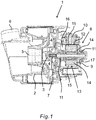
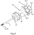
- An in Fig. 1 exemplified pump 1 of a household appliance has a pump housing 2, in which a pump impeller 3 is rotatably arranged.
- the impeller 3 has a plurality of blades 4, which are formed and arranged to suck liquid via an inlet opening 5 axially and eject via an outlet opening 6 radially.
- the pump 1 thus forms a centrifugal pump in the design of a radial pump.
- the impeller 3 is non-rotatably mounted on a motor shaft 7 of a brushless DC wet-running pump drive motor 8.
- the DC wet rotor pump drive motor 8 is disposed in a motor housing 9.
- the motor housing 9 is connected directly to the pump housing 2 in the case of the present embodiment.
- the motor housing 9 together with the pump housing 2 form a structural unit, or even be formed in one piece.
- the DC wet-rotor pump drive motor 8 has an electrically controllable stator winding 10 and a rotor 13 which can be driven in the field of the stator winding 10 and is rotatably mounted by means of the motor shaft 7 in the field between two opposite bearings 11.
- the DC wet-rotor pump drive motor 8 of the illustrated embodiment is designed as a liquid-flowed wet-rotor motor, in which the rotor 13 is mounted within a motor housing 9 in a wet space 16, which is flooded with liquid from the pump housing 2.
- the stator winding 10 is arranged in a dry environment outside of the motor housing 9.
- the rotor 13 essentially comprises the motor shaft 7, a magnet carrier 14 fixed in a rotationally fixed manner on the motor shaft 7, and permanent magnets 15 fixed to the magnet carrier 14 by means of a plastic cage 17 produced by extrusion coating.
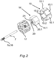
- This permanent magnet inner rotor is in Fig. 2 shown in an exploded representation closer.
- the motor shaft 7 has a front shaft end 7a to which the impeller 3 is to be fastened. At this front shaft end 7a, the motor shaft 7 on its outer circumferential wall has a knurling 18, which is designed to fix the impeller 3 rotatably on the motor shaft 7.
- the permanent magnets 15 of the rotor 13 are with their outer surfaces 15.1 in the wet space 16 in the region of an annular gap 12 between the rotor 13 and the stator winding 10 in direct contact with the liquid ( Fig. 1 ).
- the permanent magnets 15 are made of a ferromagnetic material.
- the rotatably mounted in the wet chamber 16 of the pump 1 rotatably mounted rotor 13 has a plurality of evenly distributed over a circumference arranged permanent magnets 15 whose outer surfaces 15.1 are in contact with a located in the annular gap 12 of the electric drive motor 8 liquid of the wet space 16.
- the permanent magnets 15 are held on the magnetic carrier 14 in a frame-like manner by means of a plastic cage 17 produced by encapsulation of the magnetic carrier 14.
- each permanent magnet 15 has at least one around the outer surface 15.1 circumferential chamfer 19, which is filled by the plastic cage 17, whereby the respective permanent magnet 15 form fit is enclosed by the plastic cage 17.
- the magnetic carrier 14 has a polygonal, in particular hexagonal, cross section.
- the magnetic carrier 14 may be formed solid, or be constructed of a stack of a plurality of polygonal, in particular hexagonal stamping sheets in a manner known to those skilled in the art.
- the magnet carrier 14 has a hub 20 in which the motor shaft 7 is received.
- projecting ribs 21 are provided on an inner jacket wall 20.1, which extend in particular in the axial direction.
- each permanent magnet 15 has a plane base surface 15.2, which points in the direction of the magnetic carrier 14 and covers the lateral surface 14.1 of the magnetic carrier 14 in a planar manner.
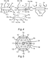
- each permanent magnet 15 has a front end wall 15.3, a rear end wall 15.4, a forward in the direction of rotation of the rotor 13 side wall 15.5 and a trailing side wall 15.6.
- the at least one chamfer 19 according to the invention is formed by the front end wall 15.3, the rear end wall 15.4, the leading side wall 15.5 and the trailing side wall 15.6 each of a vertical position L perpendicular to a base surface 15.2 of the permanent magnet 15 pointing in the direction of the magnetic carrier 14 beveled an angle a inwardly employed position, as in particular in the cross-sectional view of Fig. 4 shown, is formed.
- the angle a can lie in a value range of 1 to 20 degrees, and has a value of approximately 8 degrees, in particular in the illustrated exemplary embodiments.
- the four side edges 15a of the permanent magnet 15, which respectively directly connect the front end wall 15.3, the rear end wall 15.4, the leading side wall 15.5 and the trailing side wall 15.6, are rounded to form a single chamfer 19 encircling the outer surface 15.1 of the permanent magnet 15.
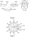
- Both in the first embodiment of according to Fig. 2 to Fig. 5 , as well as in the second embodiment according to Fig. 6 and Fig. 7 is at least one of the front end wall 15.3, the rear end wall 15.4, the leading side wall 15.5 and / or the trailing side wall 15.6 respectively directly to the outer surface 15.1 directly connecting surface edge 15b, in particular the front end wall 15.3 and the rear end wall 15.4 each with the outer surface 15.1 immediately connecting surface edges 15b provided with an additional chamfer 19b.
- the base edges 15c which in each case directly connect the front end wall 15.3, the rear end wall 15.4, the leading side wall 15.5 and the trailing side wall 15.6 with the base 15.2 of the permanent magnet 15 pointing in the direction of the magnetic carrier 14, each have a further chamfer 19c ,
- FIG. 5 shows how the overmolded plastic material of the plastic cage 17, the bevels 19 and 19c of the permanent magnets 15 according to the first embodiment form-fitting manner surrounds to hold the permanent magnets 15 to the magnetic carrier 14.
- the permanent magnets 15 are initially in accordance with their shape analogous to the first embodiment Fig. 2 to Fig. 5 educated.
- the permanent magnets 15 of the second embodiment have additionally stepped surface edges 15d.
- the stepped surface edge 15d is formed by a recess 22 having a width in the axial cross section of the permanent magnet, which is between 10% and 15%, in particular 12% or 13% of the total width of the permanent magnet.
- the stepped surface edge formed by a recess has a minimum height of at least 0.5 millimeter, in particular of at least 0.6 millimeter.
- the at least one, the front end wall 15.3, the rear end wall 15.4, the leading side wall 15.5 and / or the trailing side wall 15.6 each with the pointing in the direction of the magnetic carrier 14 base 15.2 of the permanent magnet 15 directly connecting the bottom edge 15c with provided the further chamfer 19c.
- FIG. 7 shows how the overmolded plastic material of the plastic cage 17, the chamfers 19 and 19c and the stepped recesses 22 of the permanent magnets 15 according to the second embodiment form-fitting manner to hold the permanent magnets 15 to the magnetic carrier 14.
- each permanent magnet 15 has a base 15.2 pointing in the direction of the magnetic carrier 14 and circular in cross-section, and the magnetic carrier 14 has a circular cross-section.
Landscapes
- Engineering & Computer Science (AREA)
- Power Engineering (AREA)
- Permanent Field Magnets Of Synchronous Machinery (AREA)
- Structures Of Non-Positive Displacement Pumps (AREA)
- Iron Core Of Rotating Electric Machines (AREA)
Priority Applications (1)
| Application Number | Priority Date | Filing Date | Title |
|---|---|---|---|
| PL15153872T PL2908407T3 (pl) | 2014-02-12 | 2015-02-05 | Elektryczny silnik napędowy, pompa i urządzenie gospodarstwa domowego z taką pompą |
Applications Claiming Priority (1)
| Application Number | Priority Date | Filing Date | Title |
|---|---|---|---|
| DE102014202572.9A DE102014202572A1 (de) | 2014-02-12 | 2014-02-12 | Elektrischer Antriebsmotor, Pumpe und Haushaltsgerät mit einer solchen Pumpe |
Publications (3)
| Publication Number | Publication Date |
|---|---|
| EP2908407A2 EP2908407A2 (de) | 2015-08-19 |
| EP2908407A3 EP2908407A3 (de) | 2016-03-09 |
| EP2908407B1 true EP2908407B1 (de) | 2019-01-02 |
Family
ID=52469622
Family Applications (1)
| Application Number | Title | Priority Date | Filing Date |
|---|---|---|---|
| EP15153872.5A Active EP2908407B1 (de) | 2014-02-12 | 2015-02-05 | Elektrischer Antriebsmotor, Pumpe und Haushaltsgerät mit einer solchen Pumpe |
Country Status (4)
| Country | Link |
|---|---|
| EP (1) | EP2908407B1 (pl) |
| DE (1) | DE102014202572A1 (pl) |
| ES (1) | ES2712882T3 (pl) |
| PL (1) | PL2908407T3 (pl) |
Families Citing this family (17)
| Publication number | Priority date | Publication date | Assignee | Title |
|---|---|---|---|---|
| EP3208912A1 (de) * | 2016-02-19 | 2017-08-23 | Siemens Aktiengesellschaft | Läufer |
| DE102016219973A1 (de) | 2016-10-13 | 2018-04-19 | BSH Hausgeräte GmbH | Elektrischer Antriebsmotor |
| DE102016219974B3 (de) | 2016-10-13 | 2018-03-08 | BSH Hausgeräte GmbH | Elektrischer Antriebsmotor |
| DE102016014526A1 (de) * | 2016-12-07 | 2018-06-07 | Wilo Se | Permanentmagnetrotor für eine elektrische Maschine |
| DE102017206089B4 (de) | 2017-04-10 | 2020-01-16 | BSH Hausgeräte GmbH | Nassläufer-Pumpe und Haushaltsgerät |
| DE102017206091B3 (de) | 2017-04-10 | 2018-10-11 | BSH Hausgeräte GmbH | Elektrischer Antriebsmotor, Nassläufer-Pumpe und Haushaltsgerät, sowie Verfahren zur Herstellung eines solchen elektrischen Antriebsmotors |
| DE102017206092A1 (de) * | 2017-04-10 | 2018-10-11 | BSH Hausgeräte GmbH | Elektrischer Antriebsmotor |
| CN107154692A (zh) * | 2017-06-16 | 2017-09-12 | 浙江迪贝电气股份有限公司 | 一种永磁铁氧体转子 |
| CN107634632A (zh) * | 2017-10-24 | 2018-01-26 | 江苏大学 | 一种表贴式永磁同步电机及设计方法 |
| DE102017223256A1 (de) | 2017-12-19 | 2019-06-19 | BSH Hausgeräte GmbH | Elektrischer Antriebsmotor, Nassläufer-Pumpe und Haushaltsgerät |
| JP7037970B2 (ja) * | 2018-03-16 | 2022-03-17 | 本田技研工業株式会社 | ロータ、回転電機及びロータの磁石取付方法 |
| DE102018208820A1 (de) | 2018-06-05 | 2019-12-05 | BSH Hausgeräte GmbH | Elektrischer Antriebsmotor, Nassläufer-Pumpe und Haushaltsgerät |
| DE102018116988A1 (de) * | 2018-07-13 | 2020-01-16 | Nidec Corporation | Elektromotor mit einstückigem Innenläufer-Rotorkern |
| DE102019117432A1 (de) * | 2019-06-27 | 2020-12-31 | Ebm-Papst Landshut Gmbh | Rotor für einen Elektromotor |
| DE102020109019A1 (de) * | 2020-04-01 | 2021-10-07 | Bayerische Motoren Werke Aktiengesellschaft | Rotor sowie elektrische Maschine |
| CN113206565B (zh) * | 2021-05-13 | 2022-05-27 | 珠海格力电器股份有限公司 | 一种用于电机的磁瓦以及电机转子、电机 |
| CN113364175A (zh) * | 2021-05-25 | 2021-09-07 | 浙江亚特电器有限公司 | 一种模块化嵌入式电机转子及电机 |
Citations (3)
| Publication number | Priority date | Publication date | Assignee | Title |
|---|---|---|---|---|
| JPH01286747A (ja) * | 1988-05-12 | 1989-11-17 | Toshiba Corp | インターナルポンプ |
| JPH0919091A (ja) * | 1995-06-30 | 1997-01-17 | Fanuc Ltd | 同期電動機のロータ |
| EP1967288A2 (en) * | 2007-03-08 | 2008-09-10 | General Electric Company | Rotor and stator assemblies that utilize magnetic bearings for use in corrosive environments |
Family Cites Families (6)
| Publication number | Priority date | Publication date | Assignee | Title |
|---|---|---|---|---|
| DE8427707U1 (de) * | 1984-09-20 | 1986-01-23 | Robert Bosch Gmbh, 7000 Stuttgart | Rotor für permanentmagnetisch erregte elektrische Maschinen |
| ITTO990154U1 (it) | 1999-08-06 | 2001-02-06 | Bitron Spa | Motore elettrico per la pompa della benzina di un motore a combustioneinterna. |
| JP4848580B2 (ja) * | 2000-07-13 | 2011-12-28 | パナソニック株式会社 | 永久磁石電動機の製造方法 |
| ATE414342T1 (de) * | 2000-11-30 | 2008-11-15 | C D R Pompe S P A | Mechanische, magnetkraftbetriebene antriebsvorrichtung |
| ATE467938T1 (de) * | 2005-11-18 | 2010-05-15 | Askoll Holding Srl | Verfahren zur herstellung eines permanentmagnetischen läufers für einen synchronmotor insbesondere für eine waschmaschinenpumpe für den hausgebrauch und industrielle anwendungen und ähnliches, und entsprechender läufer |
| NZ582764A (en) * | 2010-01-20 | 2012-04-27 | Wellington Drive Technologies Ltd | Rotor or stator with magnets contacting flux returns |
-
2014
- 2014-02-12 DE DE102014202572.9A patent/DE102014202572A1/de not_active Withdrawn
-
2015
- 2015-02-05 PL PL15153872T patent/PL2908407T3/pl unknown
- 2015-02-05 EP EP15153872.5A patent/EP2908407B1/de active Active
- 2015-02-05 ES ES15153872T patent/ES2712882T3/es active Active
Patent Citations (3)
| Publication number | Priority date | Publication date | Assignee | Title |
|---|---|---|---|---|
| JPH01286747A (ja) * | 1988-05-12 | 1989-11-17 | Toshiba Corp | インターナルポンプ |
| JPH0919091A (ja) * | 1995-06-30 | 1997-01-17 | Fanuc Ltd | 同期電動機のロータ |
| EP1967288A2 (en) * | 2007-03-08 | 2008-09-10 | General Electric Company | Rotor and stator assemblies that utilize magnetic bearings for use in corrosive environments |
Also Published As
| Publication number | Publication date |
|---|---|
| ES2712882T3 (es) | 2019-05-16 |
| DE102014202572A1 (de) | 2015-08-13 |
| PL2908407T3 (pl) | 2019-08-30 |
| EP2908407A2 (de) | 2015-08-19 |
| EP2908407A3 (de) | 2016-03-09 |
Similar Documents
| Publication | Publication Date | Title |
|---|---|---|
| EP2908407B1 (de) | Elektrischer Antriebsmotor, Pumpe und Haushaltsgerät mit einer solchen Pumpe | |
| EP3105838B1 (de) | Elektrischer antriebsmotor mit chromstahl, pumpe und haushaltsgerät mit einer solchen pumpe | |
| EP3011661B1 (de) | Pumpe mit einer verdrehsicherung und haushaltsgerät mit einer solchen pumpe | |
| EP0900572B1 (de) | Zentrifugalpumpe | |
| DE102011079226B4 (de) | Flüssigkeitspumpe, insbesondere Wasserpumpe | |
| EP2678921A2 (de) | Intern erregter synchronmotor mit mehrfach korrosionsgeschütztem permanentmagnetrotor | |
| EP2607710B1 (de) | Naßlaufkreiselpumpe | |
| EP4530471B1 (de) | Scrollvakuumpumpe und scrollvakuumpumpen-system | |
| EP3011663B1 (de) | Pumpe mit wenigstens einem strömungskanal und haushaltsgerät mit einer solchen pumpe | |
| DE102017206091B3 (de) | Elektrischer Antriebsmotor, Nassläufer-Pumpe und Haushaltsgerät, sowie Verfahren zur Herstellung eines solchen elektrischen Antriebsmotors | |
| DE102007049209B4 (de) | Gleichstrommotor | |
| WO2015067514A1 (de) | Elektromotorische wasserpumpe | |
| DE10240800B4 (de) | Pumpe für chemisch aggressive Fördermedien | |
| EP1079112A2 (de) | Elektromotorisch angetriebene Kreiselpumpe mit aussenliegendem Rotor | |
| EP1209799B1 (de) | Rotor einer elektrischen Maschine und Verfahren zu dessen Herstellung | |
| DE102018201841B3 (de) | Pumpenlaufrad, Verfahren zur Herstellung eines Pumpenlaufrads und Pumpe mit dem Pumpenlaufrad | |
| EP4038722B1 (de) | Permanenterregter rotor mit verbesserter magnetgeometrie | |
| WO2023104229A1 (de) | Stator für eine axialflussmaschine | |
| EP4089284B1 (de) | Nassläuferpumpe | |
| WO2023046332A1 (de) | Rotor für eine elektrische rotierende maschine, elektrische rotierende maschine, gondelantrieb und wasserfahrzeug | |
| EP1928075A2 (de) | Bürstenlose elektrische Maschine | |
| EP2778424B1 (de) | Pumpenaggregat | |
| DE202025104845U1 (de) | Rotor und Flüssigkeitspumpe dafür | |
| DE202021103004U1 (de) | Elektrische Maschine mit verbesserter direkter Flüssigkühlung | |
| DE102023105142A1 (de) | Rotoreinrichtung für eine fremderregte elektrische Maschine |
Legal Events
| Date | Code | Title | Description |
|---|---|---|---|
| PUAI | Public reference made under article 153(3) epc to a published international application that has entered the european phase |
Free format text: ORIGINAL CODE: 0009012 |
|
| AK | Designated contracting states |
Kind code of ref document: A2 Designated state(s): AL AT BE BG CH CY CZ DE DK EE ES FI FR GB GR HR HU IE IS IT LI LT LU LV MC MK MT NL NO PL PT RO RS SE SI SK SM TR |
|
| AX | Request for extension of the european patent |
Extension state: BA ME |
|
| PUAL | Search report despatched |
Free format text: ORIGINAL CODE: 0009013 |
|
| AK | Designated contracting states |
Kind code of ref document: A3 Designated state(s): AL AT BE BG CH CY CZ DE DK EE ES FI FR GB GR HR HU IE IS IT LI LT LU LV MC MK MT NL NO PL PT RO RS SE SI SK SM TR |
|
| AX | Request for extension of the european patent |
Extension state: BA ME |
|
| RIC1 | Information provided on ipc code assigned before grant |
Ipc: H02K 5/128 20060101ALI20160129BHEP Ipc: H02K 1/27 20060101AFI20160129BHEP Ipc: H02K 15/12 20060101ALN20160129BHEP |
|
| 17P | Request for examination filed |
Effective date: 20160909 |
|
| RBV | Designated contracting states (corrected) |
Designated state(s): AL AT BE BG CH CY CZ DE DK EE ES FI FR GB GR HR HU IE IS IT LI LT LU LV MC MK MT NL NO PL PT RO RS SE SI SK SM TR |
|
| 17Q | First examination report despatched |
Effective date: 20161014 |
|
| STAA | Information on the status of an ep patent application or granted ep patent |
Free format text: STATUS: EXAMINATION IS IN PROGRESS |
|
| GRAP | Despatch of communication of intention to grant a patent |
Free format text: ORIGINAL CODE: EPIDOSNIGR1 |
|
| STAA | Information on the status of an ep patent application or granted ep patent |
Free format text: STATUS: GRANT OF PATENT IS INTENDED |
|
| RIC1 | Information provided on ipc code assigned before grant |
Ipc: H02K 1/27 20060101AFI20180810BHEP Ipc: H02K 5/128 20060101ALI20180810BHEP Ipc: H02K 15/12 20060101ALN20180810BHEP |
|
| INTG | Intention to grant announced |
Effective date: 20180910 |
|
| GRAS | Grant fee paid |
Free format text: ORIGINAL CODE: EPIDOSNIGR3 |
|
| GRAA | (expected) grant |
Free format text: ORIGINAL CODE: 0009210 |
|
| STAA | Information on the status of an ep patent application or granted ep patent |
Free format text: STATUS: THE PATENT HAS BEEN GRANTED |
|
| AK | Designated contracting states |
Kind code of ref document: B1 Designated state(s): AL AT BE BG CH CY CZ DE DK EE ES FI FR GB GR HR HU IE IS IT LI LT LU LV MC MK MT NL NO PL PT RO RS SE SI SK SM TR |
|
| REG | Reference to a national code |
Ref country code: GB Ref legal event code: FG4D Free format text: NOT ENGLISH |
|
| REG | Reference to a national code |
Ref country code: CH Ref legal event code: EP Ref country code: AT Ref legal event code: REF Ref document number: 1085654 Country of ref document: AT Kind code of ref document: T Effective date: 20190115 |
|
| REG | Reference to a national code |
Ref country code: IE Ref legal event code: FG4D Free format text: LANGUAGE OF EP DOCUMENT: GERMAN |
|
| REG | Reference to a national code |
Ref country code: DE Ref legal event code: R096 Ref document number: 502015007487 Country of ref document: DE |
|
| RAP2 | Party data changed (patent owner data changed or rights of a patent transferred) |
Owner name: BSH HAUSGERAETE GMBH |
|
| REG | Reference to a national code |
Ref country code: NL Ref legal event code: MP Effective date: 20190102 |
|
| REG | Reference to a national code |
Ref country code: ES Ref legal event code: FG2A Ref document number: 2712882 Country of ref document: ES Kind code of ref document: T3 Effective date: 20190516 |
|
| REG | Reference to a national code |
Ref country code: LT Ref legal event code: MG4D |
|
| PG25 | Lapsed in a contracting state [announced via postgrant information from national office to epo] |
Ref country code: NL Free format text: LAPSE BECAUSE OF FAILURE TO SUBMIT A TRANSLATION OF THE DESCRIPTION OR TO PAY THE FEE WITHIN THE PRESCRIBED TIME-LIMIT Effective date: 20190102 |
|
| PG25 | Lapsed in a contracting state [announced via postgrant information from national office to epo] |
Ref country code: PT Free format text: LAPSE BECAUSE OF FAILURE TO SUBMIT A TRANSLATION OF THE DESCRIPTION OR TO PAY THE FEE WITHIN THE PRESCRIBED TIME-LIMIT Effective date: 20190502 Ref country code: LT Free format text: LAPSE BECAUSE OF FAILURE TO SUBMIT A TRANSLATION OF THE DESCRIPTION OR TO PAY THE FEE WITHIN THE PRESCRIBED TIME-LIMIT Effective date: 20190102 Ref country code: NO Free format text: LAPSE BECAUSE OF FAILURE TO SUBMIT A TRANSLATION OF THE DESCRIPTION OR TO PAY THE FEE WITHIN THE PRESCRIBED TIME-LIMIT Effective date: 20190402 Ref country code: SE Free format text: LAPSE BECAUSE OF FAILURE TO SUBMIT A TRANSLATION OF THE DESCRIPTION OR TO PAY THE FEE WITHIN THE PRESCRIBED TIME-LIMIT Effective date: 20190102 Ref country code: FI Free format text: LAPSE BECAUSE OF FAILURE TO SUBMIT A TRANSLATION OF THE DESCRIPTION OR TO PAY THE FEE WITHIN THE PRESCRIBED TIME-LIMIT Effective date: 20190102 |
|
| PG25 | Lapsed in a contracting state [announced via postgrant information from national office to epo] |
Ref country code: GR Free format text: LAPSE BECAUSE OF FAILURE TO SUBMIT A TRANSLATION OF THE DESCRIPTION OR TO PAY THE FEE WITHIN THE PRESCRIBED TIME-LIMIT Effective date: 20190403 Ref country code: IS Free format text: LAPSE BECAUSE OF FAILURE TO SUBMIT A TRANSLATION OF THE DESCRIPTION OR TO PAY THE FEE WITHIN THE PRESCRIBED TIME-LIMIT Effective date: 20190502 Ref country code: BG Free format text: LAPSE BECAUSE OF FAILURE TO SUBMIT A TRANSLATION OF THE DESCRIPTION OR TO PAY THE FEE WITHIN THE PRESCRIBED TIME-LIMIT Effective date: 20190402 Ref country code: RS Free format text: LAPSE BECAUSE OF FAILURE TO SUBMIT A TRANSLATION OF THE DESCRIPTION OR TO PAY THE FEE WITHIN THE PRESCRIBED TIME-LIMIT Effective date: 20190102 Ref country code: LV Free format text: LAPSE BECAUSE OF FAILURE TO SUBMIT A TRANSLATION OF THE DESCRIPTION OR TO PAY THE FEE WITHIN THE PRESCRIBED TIME-LIMIT Effective date: 20190102 Ref country code: HR Free format text: LAPSE BECAUSE OF FAILURE TO SUBMIT A TRANSLATION OF THE DESCRIPTION OR TO PAY THE FEE WITHIN THE PRESCRIBED TIME-LIMIT Effective date: 20190102 |
|
| REG | Reference to a national code |
Ref country code: CH Ref legal event code: PL |
|
| REG | Reference to a national code |
Ref country code: DE Ref legal event code: R097 Ref document number: 502015007487 Country of ref document: DE |
|
| PG25 | Lapsed in a contracting state [announced via postgrant information from national office to epo] |
Ref country code: SK Free format text: LAPSE BECAUSE OF FAILURE TO SUBMIT A TRANSLATION OF THE DESCRIPTION OR TO PAY THE FEE WITHIN THE PRESCRIBED TIME-LIMIT Effective date: 20190102 Ref country code: RO Free format text: LAPSE BECAUSE OF FAILURE TO SUBMIT A TRANSLATION OF THE DESCRIPTION OR TO PAY THE FEE WITHIN THE PRESCRIBED TIME-LIMIT Effective date: 20190102 Ref country code: CZ Free format text: LAPSE BECAUSE OF FAILURE TO SUBMIT A TRANSLATION OF THE DESCRIPTION OR TO PAY THE FEE WITHIN THE PRESCRIBED TIME-LIMIT Effective date: 20190102 Ref country code: MC Free format text: LAPSE BECAUSE OF FAILURE TO SUBMIT A TRANSLATION OF THE DESCRIPTION OR TO PAY THE FEE WITHIN THE PRESCRIBED TIME-LIMIT Effective date: 20190102 Ref country code: LU Free format text: LAPSE BECAUSE OF NON-PAYMENT OF DUE FEES Effective date: 20190205 Ref country code: AL Free format text: LAPSE BECAUSE OF FAILURE TO SUBMIT A TRANSLATION OF THE DESCRIPTION OR TO PAY THE FEE WITHIN THE PRESCRIBED TIME-LIMIT Effective date: 20190102 Ref country code: DK Free format text: LAPSE BECAUSE OF FAILURE TO SUBMIT A TRANSLATION OF THE DESCRIPTION OR TO PAY THE FEE WITHIN THE PRESCRIBED TIME-LIMIT Effective date: 20190102 Ref country code: EE Free format text: LAPSE BECAUSE OF FAILURE TO SUBMIT A TRANSLATION OF THE DESCRIPTION OR TO PAY THE FEE WITHIN THE PRESCRIBED TIME-LIMIT Effective date: 20190102 |
|
| PLBE | No opposition filed within time limit |
Free format text: ORIGINAL CODE: 0009261 |
|
| STAA | Information on the status of an ep patent application or granted ep patent |
Free format text: STATUS: NO OPPOSITION FILED WITHIN TIME LIMIT |
|
| REG | Reference to a national code |
Ref country code: BE Ref legal event code: MM Effective date: 20190228 |
|
| REG | Reference to a national code |
Ref country code: IE Ref legal event code: MM4A |
|
| PG25 | Lapsed in a contracting state [announced via postgrant information from national office to epo] |
Ref country code: SM Free format text: LAPSE BECAUSE OF FAILURE TO SUBMIT A TRANSLATION OF THE DESCRIPTION OR TO PAY THE FEE WITHIN THE PRESCRIBED TIME-LIMIT Effective date: 20190102 |
|
| 26N | No opposition filed |
Effective date: 20191003 |
|
| GBPC | Gb: european patent ceased through non-payment of renewal fee |
Effective date: 20190402 |
|
| PG25 | Lapsed in a contracting state [announced via postgrant information from national office to epo] |
Ref country code: LI Free format text: LAPSE BECAUSE OF NON-PAYMENT OF DUE FEES Effective date: 20190228 Ref country code: CH Free format text: LAPSE BECAUSE OF NON-PAYMENT OF DUE FEES Effective date: 20190228 |
|
| PG25 | Lapsed in a contracting state [announced via postgrant information from national office to epo] |
Ref country code: GB Free format text: LAPSE BECAUSE OF NON-PAYMENT OF DUE FEES Effective date: 20190402 Ref country code: IE Free format text: LAPSE BECAUSE OF NON-PAYMENT OF DUE FEES Effective date: 20190205 |
|
| PG25 | Lapsed in a contracting state [announced via postgrant information from national office to epo] |
Ref country code: BE Free format text: LAPSE BECAUSE OF NON-PAYMENT OF DUE FEES Effective date: 20190228 Ref country code: SI Free format text: LAPSE BECAUSE OF FAILURE TO SUBMIT A TRANSLATION OF THE DESCRIPTION OR TO PAY THE FEE WITHIN THE PRESCRIBED TIME-LIMIT Effective date: 20190102 Ref country code: FR Free format text: LAPSE BECAUSE OF NON-PAYMENT OF DUE FEES Effective date: 20190302 |
|
| PG25 | Lapsed in a contracting state [announced via postgrant information from national office to epo] |
Ref country code: TR Free format text: LAPSE BECAUSE OF FAILURE TO SUBMIT A TRANSLATION OF THE DESCRIPTION OR TO PAY THE FEE WITHIN THE PRESCRIBED TIME-LIMIT Effective date: 20190102 |
|
| PG25 | Lapsed in a contracting state [announced via postgrant information from national office to epo] |
Ref country code: MT Free format text: LAPSE BECAUSE OF FAILURE TO SUBMIT A TRANSLATION OF THE DESCRIPTION OR TO PAY THE FEE WITHIN THE PRESCRIBED TIME-LIMIT Effective date: 20190102 |
|
| REG | Reference to a national code |
Ref country code: AT Ref legal event code: MM01 Ref document number: 1085654 Country of ref document: AT Kind code of ref document: T Effective date: 20200205 |
|
| PG25 | Lapsed in a contracting state [announced via postgrant information from national office to epo] |
Ref country code: AT Free format text: LAPSE BECAUSE OF NON-PAYMENT OF DUE FEES Effective date: 20200205 Ref country code: CY Free format text: LAPSE BECAUSE OF FAILURE TO SUBMIT A TRANSLATION OF THE DESCRIPTION OR TO PAY THE FEE WITHIN THE PRESCRIBED TIME-LIMIT Effective date: 20190102 |
|
| PG25 | Lapsed in a contracting state [announced via postgrant information from national office to epo] |
Ref country code: HU Free format text: LAPSE BECAUSE OF FAILURE TO SUBMIT A TRANSLATION OF THE DESCRIPTION OR TO PAY THE FEE WITHIN THE PRESCRIBED TIME-LIMIT; INVALID AB INITIO Effective date: 20150205 |
|
| PG25 | Lapsed in a contracting state [announced via postgrant information from national office to epo] |
Ref country code: MK Free format text: LAPSE BECAUSE OF FAILURE TO SUBMIT A TRANSLATION OF THE DESCRIPTION OR TO PAY THE FEE WITHIN THE PRESCRIBED TIME-LIMIT Effective date: 20190102 |
|
| PGFP | Annual fee paid to national office [announced via postgrant information from national office to epo] |
Ref country code: PL Payment date: 20250127 Year of fee payment: 11 |
|
| PGFP | Annual fee paid to national office [announced via postgrant information from national office to epo] |
Ref country code: ES Payment date: 20260319 Year of fee payment: 12 |
|
| PGFP | Annual fee paid to national office [announced via postgrant information from national office to epo] |
Ref country code: DE Payment date: 20260228 Year of fee payment: 12 |
|
| PGFP | Annual fee paid to national office [announced via postgrant information from national office to epo] |
Ref country code: IT Payment date: 20260227 Year of fee payment: 12 |