EP2908309A2 - Bildanzeigevorrichtung - Google Patents
Bildanzeigevorrichtung Download PDFInfo
- Publication number
- EP2908309A2 EP2908309A2 EP15152448.5A EP15152448A EP2908309A2 EP 2908309 A2 EP2908309 A2 EP 2908309A2 EP 15152448 A EP15152448 A EP 15152448A EP 2908309 A2 EP2908309 A2 EP 2908309A2
- Authority
- EP
- European Patent Office
- Prior art keywords
- display panel
- image display
- display device
- moving bar
- calibration
- Prior art date
- Legal status (The legal status is an assumption and is not a legal conclusion. Google has not performed a legal analysis and makes no representation as to the accuracy of the status listed.)
- Ceased
Links
Images




Classifications
-
- G—PHYSICS
- G09—EDUCATION; CRYPTOGRAPHY; DISPLAY; ADVERTISING; SEALS
- G09G—ARRANGEMENTS OR CIRCUITS FOR CONTROL OF INDICATING DEVICES USING STATIC MEANS TO PRESENT VARIABLE INFORMATION
- G09G3/00—Control arrangements or circuits, of interest only in connection with visual indicators other than cathode-ray tubes
- G09G3/006—Electronic inspection or testing of displays and display drivers, e.g. of LED or LCD displays
-
- G—PHYSICS
- G01—MEASURING; TESTING
- G01J—MEASUREMENT OF INTENSITY, VELOCITY, SPECTRAL CONTENT, POLARISATION, PHASE OR PULSE CHARACTERISTICS OF INFRARED, VISIBLE OR ULTRAVIOLET LIGHT; COLORIMETRY; RADIATION PYROMETRY
- G01J3/00—Spectrometry; Spectrophotometry; Monochromators; Measuring colours
- G01J3/02—Details
- G01J3/0205—Optical elements not provided otherwise, e.g. optical manifolds, diffusers, windows
- G01J3/0237—Adjustable, e.g. focussing
-
- G—PHYSICS
- G01—MEASURING; TESTING
- G01J—MEASUREMENT OF INTENSITY, VELOCITY, SPECTRAL CONTENT, POLARISATION, PHASE OR PULSE CHARACTERISTICS OF INFRARED, VISIBLE OR ULTRAVIOLET LIGHT; COLORIMETRY; RADIATION PYROMETRY
- G01J3/00—Spectrometry; Spectrophotometry; Monochromators; Measuring colours
- G01J3/46—Measurement of colour; Colour measuring devices, e.g. colorimeters
- G01J3/50—Measurement of colour; Colour measuring devices, e.g. colorimeters using electric radiation detectors
- G01J3/506—Measurement of colour; Colour measuring devices, e.g. colorimeters using electric radiation detectors measuring the colour produced by screens, monitors, displays or CRTs
-
- G—PHYSICS
- G09—EDUCATION; CRYPTOGRAPHY; DISPLAY; ADVERTISING; SEALS
- G09G—ARRANGEMENTS OR CIRCUITS FOR CONTROL OF INDICATING DEVICES USING STATIC MEANS TO PRESENT VARIABLE INFORMATION
- G09G3/00—Control arrangements or circuits, of interest only in connection with visual indicators other than cathode-ray tubes
- G09G3/20—Control arrangements or circuits, of interest only in connection with visual indicators other than cathode-ray tubes for presentation of an assembly of a number of characters, e.g. a page, by composing the assembly by combination of individual elements arranged in a matrix no fixed position being assigned to or needed to be assigned to the individual characters or partial characters
- G09G3/2092—Details of a display terminals using a flat panel, the details relating to the control arrangement of the display terminal and to the interfaces thereto
-
- G—PHYSICS
- G09—EDUCATION; CRYPTOGRAPHY; DISPLAY; ADVERTISING; SEALS
- G09G—ARRANGEMENTS OR CIRCUITS FOR CONTROL OF INDICATING DEVICES USING STATIC MEANS TO PRESENT VARIABLE INFORMATION
- G09G5/00—Control arrangements or circuits for visual indicators common to cathode-ray tube indicators and other visual indicators
- G09G5/14—Display of multiple viewports
-
- H—ELECTRICITY
- H04—ELECTRIC COMMUNICATION TECHNIQUE
- H04N—PICTORIAL COMMUNICATION, e.g. TELEVISION
- H04N17/00—Diagnosis, testing or measuring for television systems or their details
- H04N17/04—Diagnosis, testing or measuring for television systems or their details for receivers
-
- G—PHYSICS
- G06—COMPUTING OR CALCULATING; COUNTING
- G06F—ELECTRIC DIGITAL DATA PROCESSING
- G06F1/00—Details not covered by groups G06F3/00 - G06F13/00 and G06F21/00
- G06F1/16—Constructional details or arrangements
- G06F1/1601—Constructional details related to the housing of computer displays, e.g. of CRT monitors, of flat displays
-
- G—PHYSICS
- G09—EDUCATION; CRYPTOGRAPHY; DISPLAY; ADVERTISING; SEALS
- G09G—ARRANGEMENTS OR CIRCUITS FOR CONTROL OF INDICATING DEVICES USING STATIC MEANS TO PRESENT VARIABLE INFORMATION
- G09G2320/00—Control of display operating conditions
- G09G2320/02—Improving the quality of display appearance
- G09G2320/0242—Compensation of deficiencies in the appearance of colours
-
- G—PHYSICS
- G09—EDUCATION; CRYPTOGRAPHY; DISPLAY; ADVERTISING; SEALS
- G09G—ARRANGEMENTS OR CIRCUITS FOR CONTROL OF INDICATING DEVICES USING STATIC MEANS TO PRESENT VARIABLE INFORMATION
- G09G2320/00—Control of display operating conditions
- G09G2320/06—Adjustment of display parameters
- G09G2320/0613—The adjustment depending on the type of the information to be displayed
-
- G—PHYSICS
- G09—EDUCATION; CRYPTOGRAPHY; DISPLAY; ADVERTISING; SEALS
- G09G—ARRANGEMENTS OR CIRCUITS FOR CONTROL OF INDICATING DEVICES USING STATIC MEANS TO PRESENT VARIABLE INFORMATION
- G09G2320/00—Control of display operating conditions
- G09G2320/06—Adjustment of display parameters
- G09G2320/0666—Adjustment of display parameters for control of colour parameters, e.g. colour temperature
-
- G—PHYSICS
- G09—EDUCATION; CRYPTOGRAPHY; DISPLAY; ADVERTISING; SEALS
- G09G—ARRANGEMENTS OR CIRCUITS FOR CONTROL OF INDICATING DEVICES USING STATIC MEANS TO PRESENT VARIABLE INFORMATION
- G09G2320/00—Control of display operating conditions
- G09G2320/06—Adjustment of display parameters
- G09G2320/0673—Adjustment of display parameters for control of gamma adjustment, e.g. selecting another gamma curve
-
- G—PHYSICS
- G09—EDUCATION; CRYPTOGRAPHY; DISPLAY; ADVERTISING; SEALS
- G09G—ARRANGEMENTS OR CIRCUITS FOR CONTROL OF INDICATING DEVICES USING STATIC MEANS TO PRESENT VARIABLE INFORMATION
- G09G2320/00—Control of display operating conditions
- G09G2320/06—Adjustment of display parameters
- G09G2320/0686—Adjustment of display parameters with two or more screen areas displaying information with different brightness or colours
-
- G—PHYSICS
- G09—EDUCATION; CRYPTOGRAPHY; DISPLAY; ADVERTISING; SEALS
- G09G—ARRANGEMENTS OR CIRCUITS FOR CONTROL OF INDICATING DEVICES USING STATIC MEANS TO PRESENT VARIABLE INFORMATION
- G09G2320/00—Control of display operating conditions
- G09G2320/06—Adjustment of display parameters
- G09G2320/0693—Calibration of display systems
-
- G—PHYSICS
- G09—EDUCATION; CRYPTOGRAPHY; DISPLAY; ADVERTISING; SEALS
- G09G—ARRANGEMENTS OR CIRCUITS FOR CONTROL OF INDICATING DEVICES USING STATIC MEANS TO PRESENT VARIABLE INFORMATION
- G09G2360/00—Aspects of the architecture of display systems
- G09G2360/14—Detecting light within display terminals, e.g. using a single or a plurality of photosensors
- G09G2360/145—Detecting light within display terminals, e.g. using a single or a plurality of photosensors the light originating from the display screen
-
- H—ELECTRICITY
- H04—ELECTRIC COMMUNICATION TECHNIQUE
- H04N—PICTORIAL COMMUNICATION, e.g. TELEVISION
- H04N21/00—Selective content distribution, e.g. interactive television or video on demand [VOD]
- H04N21/40—Client devices specifically adapted for the reception of or interaction with content, e.g. set-top-box [STB]; Operations thereof
- H04N21/41—Structure of client; Structure of client peripherals
- H04N21/422—Input-only peripherals, i.e. input devices connected to specially adapted client devices, e.g. global positioning system [GPS]
- H04N21/42202—Input-only peripherals, i.e. input devices connected to specially adapted client devices, e.g. global positioning system [GPS] environmental sensors, e.g. for detecting temperature, luminosity, pressure, earthquakes
Definitions
- the present invention relates to an image display device with a calibration sensor.
- Image display devices include every device that receives and outputs a broadcast, or records and plays video or audio. Examples of this image display device include a television, a monitor, a projector, a tablet, etc.
- image display devices As the functions of image display devices are diversified, they are being implemented in the form of a multimedia player equipped with complex functions, such as photographing and video capturing functions, gaming functions, broadcast reception functions, as well as broadcast outputting functions and video playback functions.
- complex functions such as photographing and video capturing functions, gaming functions, broadcast reception functions, as well as broadcast outputting functions and video playback functions.
- the color, brightness, and saturation of a display panel for an image display device can change slightly over time. Even minor differences among types of hardware or software may cause subtle differences in color on the same display panel. Accordingly, these factors should be adjusted for the display panel to produce the best color possible.
- the adjustment is made by resetting control signals for the display panel based on values detected by an optical sensor such as a calibration sensor.
- an optical sensor such as a calibration sensor.
- the principle of calibration is widely known in the art.
- An aspect of the present invention is to provide an image display device capable of calibrating a certain area of a display panel using a built-in calibration sensor.
- an image display device including: a display panel that outputs visual information; a casing that holds the display panel; a moving bar that is mounted on the casing and configured to be movable in a first direction while overlapping the display panel; a calibration sensor that is mounted at the moving bar so as to be movable in a second direction perpendicular to the first direction and obtains calibration information for the display panel; and a controller that controls the display panel using the obtained calibration information.
- the moving bar is configured to be held in a holder portion provided on one side of the display panel.
- the holder portion may be placed at the lower edge of the display panel, and the moving bar may be configured to be movable from the lower edge of the display panel to the upper edge.
- the casing and the moving bar may lie in a plane perpendicular to the display panel while the moving bar is held in the holder portion.
- the calibration sensor is configured to face the display panel, and a shielding wall protruding toward the display panel is formed on the moving bar so that ambient light is shielded when the calibration sensor obtains calibration information.
- the shielding wall may extend along the circumference of the moving bar so as to surround the calibration sensor.
- a lead screw with a thread on the outer circumference may be placed on at least one side of the casing to extend along the side of the casing and rotate by a driving unit, and the moving bar may be screwed to the lead screw and move in the first direction as the lead screw turns.
- the moving bar comprises: a lead screw with a thread on the outer circumference that extends in the lengthwise direction of the moving bar; a driving unit that turns the lead screw; and a moving member where the calibration sensor is mounted and which is screwed to the lead screw and moves in the second direction as the lead screw turns.
- the calibration sensor may be configured to be movable toward a certain area once the moving member is placed on the certain area.
- the display panel is divided into a plurality of screen regions that output different information, and the controller controls the position of the calibration sensor to obtain calibration information for each of the screen regions.
- the controller may control the position of the calibration sensor so that the calibration sensor is positioned sequentially in the divided regions.
- the controller may do a calculation on the central area of each of the screen regions and position the calibration sensor in each central area.
- the controller may divide the rest of the screen region, excluding the another screen region, into a plurality of sub regions, do a calculation on the central area of one of the divided sub regions, and position the calibration sensor in the central area.
- the one of the divided sub regions may be the largest.
- the image display device further includes a memory unit that contains calibration information optimized for each screen mode, and the controller controls the display panel through a comparative analysis of the obtained calibration information and the optimized calibration information.
- the optimized calibration information may include color temperature information and gamma value information.
- a singular representation may include a plural representation unless it represents a definitely different meaning from the context.
- An image display device related to the present invention includes every device equipped with a display panel, such as a device for receiving and outputting broadcasts, a device for playing back videos, etc.
- a display panel such as a device for receiving and outputting broadcasts, a device for playing back videos, etc.
- the image display device related to the present invention will be described taking a television as an example.
- FIG. 1 is a block diagram for explaining a calibration process of an image display device 100 related to the present invention.
- the image display device 100 includes a display panel 110 that outputs visual information, a calibration sensor 140 that obtains calibration information for the display panel 110, a controller 150 with an image processor 151, and a memory unit 160 that stores calibration information.
- Other components of the image display device 100 are not directly related to the following description, so they will be omitted.
- the calibration sensor 140 When a control command associated with calibration is issued, the calibration sensor 140 obtains calibration information for (e.g., the color, brightness, saturation, etc of) the display panel 110.
- the calibration sensor 140 may be placed in a certain area of the display panel 110 and obtain calibration information by a mechanism to be described later.
- the memory unit 160 stores calibration information optimized for the display panel 110.
- the optimized calibration information may include calibration information optimized for each screen mode (e.g., video playback mode, text output mode, search mode, etc).
- Such optimized calibration information may include color temperature information and gamma value information which are optimized for each screen mode.
- the controller 150 controls all the components including the calibration sensor 140.
- the image processor 151 provided in the controller 150 generates a control signal for controlling the display panel 100 by using calibration information.
- the image display device 100 capable of calibrating a certain area of the display panel 110 using the built-in calibration sensor 140 will be described in more detail.
- FIG. 2 is a conceptual diagram showing an example of the image display device related to the present invention.
- FIG. 3 is a conceptual diagram showing the moving bar 130 of FIG. 2 moving in a first direction.
- FIG. 4 is a conceptual diagram showing the calibration sensor 140 of FIG. 2 moving in a second direction.
- the image display device 100 includes a display panel 110, a casing 120, a moving bar 130, a calibration sensor 140, and a controller 150.
- the display panel 110 can convert a video signal, data signal, or OSD signal processed by the controller 150 into an RGB signal to generate a driving signal. By this, the display panel 110 outputs visual information.
- the display panel 110 can be implemented in various forms, such as a plasma display panel PDP, a liquid crystal display LCD, a thin film transistor-liquid crystal display TFT-LCD, an organic light emitting diode OLED, a flexible display, a 3D display, an e-ink display, etc.
- the display panel 110 can be implemented as a touch screen by forming an interlayer with a touch sensor or by being integrated with it.
- This touch screen can function as a user input unit that provides an input interface between the image display device 100 and the user.
- the casing 120 accommodates the display panel 110, and constitutes the appearance of the image display device 100.
- the casing 120 may be called other terms, like frame, housing, cover, and so on. As shown in the drawings, the casing 120 may be configured to cover the edge of the display panel 110.
- the moving bar 130 is movably mounted on the casing 120.
- the moving bar 130 is in the shape of a bar that extends longitudinally towards both sides of the display panel 110.
- the moving bar 130 is configured to be movable in the first direction while overlapping the display panel 110.
- FIG. 2 illustrates that the moving bar 130 is arranged longitudinally in the transverse direction of the display panel 110 and movable between the upper and lower edges of the display panel 100.
- the calibration sensor 140 is mounted at the moving bar 130 so as to be movable in a second direction perpendicular to the first direction and obtains calibration information for the display panel 110.
- FIG. 3 illustrates that the calibration sensor 140 is mounted to be movable along the direction of extension of the moving bar 130 and this results in making the display panel 100 movable to the left and right sides of the display panel 110.
- a certain area of the display panel 110 can be calibrated as the moving bar 130 is configured to be movable in the first direction while overlapping the display panel 110 and the calibration sensor 140 is mounted at the moving bar 130 so as to be movable in the second direction perpendicular to the first direction.
- the controller 150 controls the display panel 110 using obtained calibration information.
- the image processor provided in the controller 150 can do a comparative analysis of the optimized calibration information stored in the memory unit 160 and the calibration information obtained by the calibration sensor 140 and convert an RGB signal the display panel 110 receives.
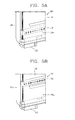
- FIGS. 5A and 5B are conceptual diagrams showing the moving bar 130 of FIG. 2 held in a holder portion 120a and the moving bar 130 of FIG. 2 being pulled out from the holder portion 120a, respectively.
- FIG. 6 is an enlarged view of the part A shown in FIG. 3 .
- the holder portion 120a for holding the moving bar 130 is provided on one side of the display panel 100.
- the holder portion 120a may be a space between the display panel 110 and the casing 120 or a space formed in the casing 120.
- the moving bar 130 is held in the holder portion 120a so as not to cover the visual information output on the display panel 110 while calibration is not performed.
- the casing 120 may be configured to cover the moving bar 130 to avoid the moving bar 130 from being visible on the front side of the display panel 110 when the moving bar 130 is held in the holder portion 120a. That is, the moving bar 130 is held in the holder portion 120a and covered and hidden by the casing 120.
- the casing 120 and the moving bar 130 may lie in a plane perpendicular to the display panel 110 while the moving bar 130 is held in the holder portion 120a. Accordingly, no level difference occurs between the casing 12 and the moving bar 130 while the moving bar 130 is held, which smartens up the appearance.
- the holder portion 120a may be provided on one side of the display panel 110. This drawing illustrates that the holder portion 120a is provided at the lower edge of the display panel 110 and the moving bar 130 is configured to move from the lower edge of the display panel 110 to the top edge. It is to be noted that the moving bar 130 can be configured to move from the upper edge of the display panel 110 to the lower edge.
- the moving bar 120a can also be provided on the top edge of the display panel 110.
- the controller 150 can control the movement of the moving bar 130 so that the moving bar 130 is held in the adjacent one of two holder portions 120a on either edge, after obtaining calibration information for a certain area of the display panel 110. Accordingly, calibration can be done faster.
- a lead screw 171 with a thread on the outer circumference is placed on at least one side of the casing 120 to extend along the side of the casing 120 and rotate by a driving unit 172.
- This drawing illustrates that the lead screw 171 is arranged longitudinally on the left side of the case 120 in the lengthwise direction of the display panel 110.
- the moving bar 130 is screwed to the lead screw 171 and move as the lead screw 171 turns in the first direction. For example, when the lead screw 171 rotates in one direction, the moving bar 130 moves from the lower edge of the display panel 110 to the upper edge, and when the lead screw 171 rotates in the other direction, the moving bar 130 moves from the upper edge of the display panel 110 to the lower edge.
- the above structure also may be provided symmetrically on the right side of the casing 120.
- a guide structure for guiding the movement of the moving bar 130 may be provided on the right side of the casing 120.
- a guide bar is longitudinally arranged on the right side of the casing 120 in the lengthwise direction of the display panel 110, and the right side of the moving bar 130 may be connected to the guide bar and guided during movement.
- FIG. 7 is a conceptual diagram showing the inside of the moving bar 130 of FIG. 2 .
- the calibration sensor 140 is configured to be held in the moving bar 130 and face the display panel 110. If ambient light enters during calibration, this makes it difficult to obtain accurate calibration information.
- a shielding wall 131 protruding toward the display panel 110 is formed on the moving bar 130 so that the ambient light is shielded when the calibration sensor 140 obtains calibration information.
- the shielding wall 131 may extend along the circumference of the moving bar 130 so as to surround the calibration sensor 140.
- the shielding wall 131 can maintain contact with the display panel 110 when the moving bar 130 moves.
- a protective sheet of fibrous material e.g., non-woven fabric
- the moving bar 130 includes a holder portion 130a.
- a lead screw 181, driving unit 182, and moving member 183 can be mounted in the holder portion 130a to move the calibration sensor 140.
- the lead screw 181 with a thread on the outer circumference is placed on the moving bar 130 to extend along the length of the moving bar 120 and rotate by the driving unit 182.
- the lead screw 181 for moving the calibration sensor 140 is placed perpendicular to the lead screw 171 for moving the moving bar 130.
- the calibration sensor 140 is mounted at the moving member 183, and the moving member 183 is configured to be screwed to the lead screw 181 movable in the second direction as the lead screw 181 rotates. That is, the moving member 183 moves from one side to the other side or vice versa according to the direction of rotation of the lead screw 181.
- the calibration sensor 140 may be configured to be movable toward a certain area once the moving member 183 is placed on the certain area. Also, this movement of the calibration sensor 140 may cause the calibration sensor 140 to come into contact with the display panel 110. To accomplish this, a driving unit for moving the calibration sensor 140 in a third direction perpendicular to the first and second directions may be mounted at the moving member 183. This allows for more accurate calibration.
- FIGS. 8 to 10 are conceptual diagrams showing examples of calibration in the image display device 100 of FIG. 2 .
- FIG. 8 illustrates that calibration is performed while the display panel 110 is outputting one piece of information.
- the central area of the display panel 110 can be calibrated. Accordingly, as shown in this drawing, the controller 150 can do a calculation on the central area of the display panel 110 and position the calibration sensor 140 in the central area.
- the controller 150 can divide the display panel 110 into a plurality of regions and calibrate the divided regions.
- the controller 150 may control the position of the calibration sensor 140 so that the calibration sensor 140 is positioned sequentially in the divided regions. This allows for more accurate calibration of the display panel 110.
- FIGS. 9 and 10 illustrate that calibration is performed after the display panel 110 is divided into a plurality of screen regions 100a and 110b; or 110c and 110d which output different information.
- FIG. 9 shows another screen region 110a which is positioned within one screen region 110a (PIP: Picture In Picture).
- FIG. 10 shows a plurality of screen regions 110c and 110d which are positioned left and right or up and down in such a way that they do not overlap each other.
- the controller 150 can control the position of the calibration sensor 140 to obtain calibration information for each of the screen regions 110a and 110b; or 110c and 110d.
- the controller 150 may control the calibration sensor 140 so that the calibration sensor 140 is positioned sequentially in the screen regions 110a and 110b; or 110c and 110d according to a set criteria.
- the calibration sensor 140 may be positioned in the screen regions 110a and 110b; or 110c and 110d from larger to smaller or from left to right.
- the controller 150 can do a calculation on the central area of each of the screen regions 110a and 110b; or 110c and 110d and position the calibration sensor 140 in each central area.
- the controller 150 may divide the rest of the one screen region 110a, excluding the another screen region 110b, into a plurality of sub regions, do a calculation on the central area of one of the divided sub regions, and position the calibration sensor 140 in the central area.
- the one of the divided sub regions may be the largest. This is to increase calibration efficiency by substantially calibrating the most noticeable region.
- the criteria for division into a plurality of sub regions may vary according to the user settings. Besides, all of the divided sub regions may be sequentially calibrated for more accurate calibration.
- the screen regions 110a and 110b; or 110c and 110d can be driven in different modes. For example, one screen region can be driven in video playback mode, and the other screen region can be driven in text output mode.
- the memory unit 160 can include calibration information optimized for each screen mode, and the controller 150 can control each of the screen regions 110a and 110b; or 110c and 110d through a comparative analysis of the obtained calibration information and the optimized calibration information.
- the controller 150 can control the calibration sensor 140 so that each of the screen regions 110a and 110b; or 110c and 110d is calibrated. Accordingly, optimized visual information can be provided for each of the divided screen regions 110a and 110b; or 110c and 110d.
Landscapes
- Engineering & Computer Science (AREA)
- Physics & Mathematics (AREA)
- General Physics & Mathematics (AREA)
- Spectroscopy & Molecular Physics (AREA)
- Theoretical Computer Science (AREA)
- Computer Hardware Design (AREA)
- Multimedia (AREA)
- Signal Processing (AREA)
- Health & Medical Sciences (AREA)
- General Health & Medical Sciences (AREA)
- Biomedical Technology (AREA)
- Controls And Circuits For Display Device (AREA)
- Testing, Inspecting, Measuring Of Stereoscopic Televisions And Televisions (AREA)
- User Interface Of Digital Computer (AREA)
- Devices For Indicating Variable Information By Combining Individual Elements (AREA)
- Control Of Indicators Other Than Cathode Ray Tubes (AREA)
Applications Claiming Priority (1)
| Application Number | Priority Date | Filing Date | Title |
|---|---|---|---|
| KR1020140016114A KR20150095056A (ko) | 2014-02-12 | 2014-02-12 | 영상표시기기 |
Publications (2)
| Publication Number | Publication Date |
|---|---|
| EP2908309A2 true EP2908309A2 (de) | 2015-08-19 |
| EP2908309A3 EP2908309A3 (de) | 2015-10-28 |
Family
ID=52394171
Family Applications (1)
| Application Number | Title | Priority Date | Filing Date |
|---|---|---|---|
| EP15152448.5A Ceased EP2908309A3 (de) | 2014-02-12 | 2015-01-26 | Bildanzeigevorrichtung |
Country Status (4)
| Country | Link |
|---|---|
| US (1) | US9640098B2 (de) |
| EP (1) | EP2908309A3 (de) |
| KR (1) | KR20150095056A (de) |
| CN (1) | CN104837040B (de) |
Cited By (2)
| Publication number | Priority date | Publication date | Assignee | Title |
|---|---|---|---|---|
| DE102016206585A1 (de) * | 2016-04-19 | 2017-10-19 | Siemens Aktiengesellschaft | Anzeigevorrichtung sowie Verfahren zum Erfassen von Prüfdaten |
| EP3574639A4 (de) * | 2017-07-13 | 2020-07-29 | Hewlett-Packard Development Company, L.P. | Monitorkalibrierung |
Families Citing this family (7)
| Publication number | Priority date | Publication date | Assignee | Title |
|---|---|---|---|---|
| CN105023512B (zh) * | 2015-07-23 | 2018-08-24 | 苏州佳世达电通有限公司 | 显示设备 |
| JP2019535031A (ja) | 2016-10-20 | 2019-12-05 | ヒューレット−パッカード デベロップメント カンパニー エル.ピー.Hewlett‐Packard Development Company, L.P. | 較正装置を有するディスプレイ |
| CN108491111B (zh) * | 2018-05-19 | 2024-07-26 | 江西盛显科技有限公司 | 一种触摸屏频点校准装置及校准方法 |
| CN109521592B (zh) * | 2018-12-18 | 2022-04-12 | 苏州佳世达电通有限公司 | 显示设备 |
| CN112017614A (zh) * | 2019-05-29 | 2020-12-01 | 宏碁股份有限公司 | 色彩校正系统及显示器 |
| CN113141739B (zh) * | 2020-01-20 | 2023-02-03 | 苏州佳世达电通有限公司 | 校色器 |
| KR102754312B1 (ko) * | 2023-04-25 | 2025-01-14 | 엘지전자 주식회사 | 디스플레이 장치 |
Citations (2)
| Publication number | Priority date | Publication date | Assignee | Title |
|---|---|---|---|---|
| US20050190136A1 (en) * | 2003-12-19 | 2005-09-01 | Siemens Aktiengesellschaft | Arrangement with a flat screen panel |
| WO2012172707A1 (ja) * | 2011-06-14 | 2012-12-20 | 株式会社ナナオ | 光センサ装置及び画像表示装置 |
Family Cites Families (6)
| Publication number | Priority date | Publication date | Assignee | Title |
|---|---|---|---|---|
| US6271825B1 (en) | 1996-04-23 | 2001-08-07 | Rainbow Displays, Inc. | Correction methods for brightness in electronic display |
| JP2002098641A (ja) | 2000-09-21 | 2002-04-05 | Olympus Optical Co Ltd | 大型基板検査装置 |
| US6933967B2 (en) * | 2002-09-10 | 2005-08-23 | Sony Corporation | Color reference system for display monitor |
| US7633550B1 (en) | 2004-09-13 | 2009-12-15 | Intermec Ip Corp. | Apparatus and method for display screen flicker detection and correction |
| US20070120763A1 (en) | 2005-11-23 | 2007-05-31 | Lode De Paepe | Display system for viewing multiple video signals |
| US20080294298A1 (en) | 2007-04-11 | 2008-11-27 | Dooyang Systems Inc. | Automatic transportation apparatus of characteristic value measurement sensor unit of video appliance and transportation method of the same |
-
2014
- 2014-02-12 KR KR1020140016114A patent/KR20150095056A/ko not_active Withdrawn
- 2014-12-05 US US14/561,647 patent/US9640098B2/en active Active
-
2015
- 2015-01-22 CN CN201510032754.XA patent/CN104837040B/zh not_active Expired - Fee Related
- 2015-01-26 EP EP15152448.5A patent/EP2908309A3/de not_active Ceased
Patent Citations (3)
| Publication number | Priority date | Publication date | Assignee | Title |
|---|---|---|---|---|
| US20050190136A1 (en) * | 2003-12-19 | 2005-09-01 | Siemens Aktiengesellschaft | Arrangement with a flat screen panel |
| WO2012172707A1 (ja) * | 2011-06-14 | 2012-12-20 | 株式会社ナナオ | 光センサ装置及び画像表示装置 |
| EP2722836A1 (de) * | 2011-06-14 | 2014-04-23 | EIZO Corporation | Optische sensorvorrichtung und bildanzeigevorrichtung |
Cited By (3)
| Publication number | Priority date | Publication date | Assignee | Title |
|---|---|---|---|---|
| DE102016206585A1 (de) * | 2016-04-19 | 2017-10-19 | Siemens Aktiengesellschaft | Anzeigevorrichtung sowie Verfahren zum Erfassen von Prüfdaten |
| EP3574639A4 (de) * | 2017-07-13 | 2020-07-29 | Hewlett-Packard Development Company, L.P. | Monitorkalibrierung |
| US11232765B2 (en) | 2017-07-13 | 2022-01-25 | Hewlett-Packard Development Company, L.P. | Monitor calibration |
Also Published As
| Publication number | Publication date |
|---|---|
| US9640098B2 (en) | 2017-05-02 |
| EP2908309A3 (de) | 2015-10-28 |
| CN104837040B (zh) | 2019-02-12 |
| KR20150095056A (ko) | 2015-08-20 |
| CN104837040A (zh) | 2015-08-12 |
| US20150228213A1 (en) | 2015-08-13 |
Similar Documents
| Publication | Publication Date | Title |
|---|---|---|
| US9640098B2 (en) | Image display device | |
| CN105993044B (zh) | 显示设备及其控制方法 | |
| JP4495518B2 (ja) | 番組選択支援装置及び番組選択支援プログラム | |
| US9264700B2 (en) | Multi viewer display and displaying method of the same | |
| KR102483086B1 (ko) | 영상표시장치 | |
| KR102300925B1 (ko) | 영상표시기기 | |
| KR100703939B1 (ko) | 영상처리장치 및 영상처리방법 | |
| US20120127285A1 (en) | Synchronization apparatus and synchronization method | |
| JP2012252415A (ja) | 情報処理装置及びキャリブレーション方法 | |
| CN107615134B (zh) | 头戴式显示装置 | |
| CN100542234C (zh) | 显示设备及其控制方法 | |
| US20170074452A1 (en) | Display apparatus and control method thereof | |
| KR20130011041A (ko) | 영상표시장치 및 그 동작방법 | |
| US10488576B2 (en) | Image display apparatus | |
| US20070058080A1 (en) | Video processing apparatus and video processing method | |
| KR20140002353A (ko) | 디스플레이장치 및 그 캘리브레이션 방법 | |
| KR102957827B1 (ko) | 디스플레이 장치 및 그 동작방법 | |
| JP2008085407A (ja) | 携帯型電子機器および液晶ディスプレ用のフード | |
| EP3389266B1 (de) | Betrachtungsvorrichtung und verfahren | |
| US20100164988A1 (en) | Image Display Device and Image Display Method | |
| JP2009017197A (ja) | テレビジョン受像機 | |
| JP2012252708A (ja) | 情報処理装置、キャリブレーション方法及びプログラム | |
| JP4580907B2 (ja) | 推奨視聴位置指示装置、テレビジョン受像機、推奨視聴位置指示方法 | |
| JP2010028719A (ja) | 電子装置カバー及びディスプレイ装置 | |
| US20130031583A1 (en) | Electronic apparatus, control method of electronic apparatus and non-transitory computer-readable medium storing computer executable control program of electronic apparatus |
Legal Events
| Date | Code | Title | Description |
|---|---|---|---|
| PUAI | Public reference made under article 153(3) epc to a published international application that has entered the european phase |
Free format text: ORIGINAL CODE: 0009012 |
|
| 17P | Request for examination filed |
Effective date: 20150126 |
|
| AK | Designated contracting states |
Kind code of ref document: A2 Designated state(s): AL AT BE BG CH CY CZ DE DK EE ES FI FR GB GR HR HU IE IS IT LI LT LU LV MC MK MT NL NO PL PT RO RS SE SI SK SM TR |
|
| AX | Request for extension of the european patent |
Extension state: BA ME |
|
| PUAL | Search report despatched |
Free format text: ORIGINAL CODE: 0009013 |
|
| AK | Designated contracting states |
Kind code of ref document: A3 Designated state(s): AL AT BE BG CH CY CZ DE DK EE ES FI FR GB GR HR HU IE IS IT LI LT LU LV MC MK MT NL NO PL PT RO RS SE SI SK SM TR |
|
| AX | Request for extension of the european patent |
Extension state: BA ME |
|
| RBV | Designated contracting states (corrected) |
Designated state(s): AL AT BE BG CH CY CZ DE DK EE ES FI FR GB GR HR HU IE IS IT LI LT LU LV MC MK MT NL NO PL PT RO RS SE SI SK SM TR |
|
| 17Q | First examination report despatched |
Effective date: 20160315 |
|
| STAA | Information on the status of an ep patent application or granted ep patent |
Free format text: STATUS: THE APPLICATION HAS BEEN REFUSED |
|
| 18R | Application refused |
Effective date: 20170427 |