EP2908276A1 - Verwaltung von in Möbelstücken in Gebäuden aufbewahrten Artikelbeständen - Google Patents
Verwaltung von in Möbelstücken in Gebäuden aufbewahrten Artikelbeständen Download PDFInfo
- Publication number
- EP2908276A1 EP2908276A1 EP14305208.2A EP14305208A EP2908276A1 EP 2908276 A1 EP2908276 A1 EP 2908276A1 EP 14305208 A EP14305208 A EP 14305208A EP 2908276 A1 EP2908276 A1 EP 2908276A1
- Authority
- EP
- European Patent Office
- Prior art keywords
- furniture
- pieces
- items
- facility
- processing system
- Prior art date
- Legal status (The legal status is an assumption and is not a legal conclusion. Google has not performed a legal analysis and makes no representation as to the accuracy of the status listed.)
- Ceased
Links
Images


Classifications
-
- G—PHYSICS
- G06—COMPUTING; CALCULATING OR COUNTING
- G06Q—INFORMATION AND COMMUNICATION TECHNOLOGY [ICT] SPECIALLY ADAPTED FOR ADMINISTRATIVE, COMMERCIAL, FINANCIAL, MANAGERIAL OR SUPERVISORY PURPOSES; SYSTEMS OR METHODS SPECIALLY ADAPTED FOR ADMINISTRATIVE, COMMERCIAL, FINANCIAL, MANAGERIAL OR SUPERVISORY PURPOSES, NOT OTHERWISE PROVIDED FOR
- G06Q10/00—Administration; Management
- G06Q10/08—Logistics, e.g. warehousing, loading or distribution; Inventory or stock management
- G06Q10/087—Inventory or stock management, e.g. order filling, procurement or balancing against orders
-
- G—PHYSICS
- G06—COMPUTING; CALCULATING OR COUNTING
- G06K—GRAPHICAL DATA READING; PRESENTATION OF DATA; RECORD CARRIERS; HANDLING RECORD CARRIERS
- G06K7/00—Methods or arrangements for sensing record carriers, e.g. for reading patterns
- G06K7/10—Methods or arrangements for sensing record carriers, e.g. for reading patterns by electromagnetic radiation, e.g. optical sensing; by corpuscular radiation
- G06K7/10009—Methods or arrangements for sensing record carriers, e.g. for reading patterns by electromagnetic radiation, e.g. optical sensing; by corpuscular radiation sensing by radiation using wavelengths larger than 0.1 mm, e.g. radio-waves or microwaves
- G06K7/10316—Methods or arrangements for sensing record carriers, e.g. for reading patterns by electromagnetic radiation, e.g. optical sensing; by corpuscular radiation sensing by radiation using wavelengths larger than 0.1 mm, e.g. radio-waves or microwaves using at least one antenna particularly designed for interrogating the wireless record carriers
- G06K7/10356—Methods or arrangements for sensing record carriers, e.g. for reading patterns by electromagnetic radiation, e.g. optical sensing; by corpuscular radiation sensing by radiation using wavelengths larger than 0.1 mm, e.g. radio-waves or microwaves using at least one antenna particularly designed for interrogating the wireless record carriers using a plurality of antennas, e.g. configurations including means to resolve interference between the plurality of antennas
Definitions
- the present invention generally relates to the automatic stock management in facilities storing items.
- the present invention relates to the management of stocks of items directly disposed in pieces of furniture in said facilities, in order to organise the provisioning.
- brands can place pieces of furniture containing manufactured goods to be sold to customers.
- the brand directly provides the store or the supermarket with the goods and also the pieces of furniture (typically a gondola).
- the brand does not have stocks within the store and the only goods it has available at the store are those presented in the piece of furniture.
- RFID systems are used in many different applications including, in particular, retail applications for managing inventory.
- an RFID reader comprising an antenna interrogates RFID tags located in the vicinity of the reader's antenna.
- the kind of information returned by an RFID tag depends on its type.
- the data read on an RFID tag generally relates to the identification of the item associated with the RFID tag.
- identification may comprise an identifier of the item, a description of the item, an identifier of the manufacturer of the item, and the like.
- One of the main advantages of the use of RFID technology over other technologies like barcode technology lies in its capacity to interrogate several RFID tags simultaneously that may not be in direct line of sight of the reader.
- RFID tags for their localization (that is to say, for identifying the location of the items).
- RFID tags for localizing an object such as a wallet or to help in controlling movements of a robot.
- RFID tags can be usefully implemented in facilities, in particular in retail areas, for example to help customers localize desired items, to help storekeepers in supplying gondolas and to verify that each item is at its correct place.
- GPS Global Positioning System
- RFID readers that can be mobile or not. Accordingly, after detecting an RFID tag, an RFID reader can obtain identification data from the RFID tag and localization data from a GPS module. These data may be combined so as to provide RFID tag identification and position data to a central processing system.
- GPS based solutions are not adapted for indoor use because of signal attenuation.
- GPS solutions are not adapted to accurately determine the elevation of an item.
- the coordinates of the RFID tags are stored in the latter.
- an RFID writer having positioning means or having means for determining the current or future positions of the RFID tags is used to program the tags.
- Such a solution presents several drawbacks among which is storage of the coordinates of each RFID tag in its memory.
- Still other solutions are based on triangulation or trilateration using received signal strength, round-trip time-of-flight, time-difference-of-arrival, and/or phase-difference-of-arrival.
- these solutions may enable accurate positioning measurements to be obtained, they are difficult to implement in a real environment.
- RFID tags may present numerous advantages over traditional technologies, there remain some drawbacks.
- RFID readers are generally expensive and the communication range allowing communication between an RFID reader and a low cost RFID tag is limited.
- antennas can be connected to a single RFID reader via a multiplexer which is used to select the antenna to be used.
- the antennas used for retail applications are typically patch antennas that is to say planar resonant antennas for narrow-band microwave wireless links that require semi-hemispherical coverage. They are often used as elements for an array. It is noted that most retail applications are based upon UHF (Ultra High Frequency) RFID tags whose signal frequency is comprised between 860 and 960 MHz.
- UHF Ultra High Frequency
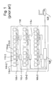
- FIG. 1 illustrates schematically a back view of a back panel 100 of a shelving structure comprising horizontal shelves 105-1 to 105-3 for CDs, DVDs, books, or the like.
- back panel 100 includes an RFID infrastructure. More precisely, back panel 100 comprises several arrays of antennas, each array of antennas being associated with one multiplexer allowing the selection of an antenna in the array. For example, each of the antennas 110-1 to 110-5 is connected to the multiplexer 115-1. Similarly, antennas are connected to the multiplexer 115-1, as shown.
- multiplexers 115-1 and 115-i are themselves connected to another multiplexer 120.
- multiplexer 120 is typically connected to an electronic circuit 125 comprising a microprocessor, for example a personal computer. Accordingly, the electronic circuit 125 can select and activate one antenna amongst all the antennas of the back panel 100 by controlling paths established by the multiplexers.
- the activation of an antenna allows electronic tags located in its vicinity to be read. For the sake of illustration, the activation of antenna 110-3 allows access to the information stored in the RFID tags attached to the items located in front of the antenna 110-3 (in front of the back panel 100) on the horizontal shelf 105-1.
- said first and/or second numbers are determined in real-time.
- said first and/or second numbers are regularly determined.
- the method may further comprise a step of receiving a request for stock information from said stock management system, and said stock information may be transmitted in response to said request.
- said stock information is regularly transmitted to said stock management system.
- said stock information is transmitted over a public telecommunication network.
- said first and second numbers are determined for types of items, and the stock information enables to trigger supply of the facilities for meeting respective needs of each facility for items
- said stock information comprises first localization information for localizing the items in the corresponding piece of furniture.
- said stock information comprises second localization information for localizing the facility from which it originates.
- said step of determining said first number is performed by each local processing system associated with a set of pieces of furniture.
- said step of determining said second total number and/ or said step of transmitting said stock information is performed, in each facility, by a central processing unit to which are connected each processing system.
- the advantages provided by such a computer program are similar to those described above.
- a central computing system of a facility is connected to several local processing systems.
- Each local processing system comprises at least one electronic tag reader that is connected to several antennas that are mounted within pieces of furniture.
- the relative positions of the antennas within the pieces of furniture are known or can be obtained by the corresponding local processing system so that an antenna can be localized for example as a function of the multiplexer or switches used to activate the antenna and according to a predetermined setting.
- the central computing system can access a layout mapping of the pieces of furniture in the facility.
- patch antennas are used to interrogate RFID tags of the UHF type whose signal frequency is approximately equal to 860 MHz or to 960 MHz.
- the patch antenna structure is designed so as to minimize the amount of cabling and the number of UHF connectors.
- parts of the furniture can be used as elements of the patch antennas. More precisely, parts of the furniture comprising parts of the RFID system are preconfigured as pre-cabled modules so as to reduce the number of connexions to make, in particular connexions for RF and control signals, when retail furniture is to be installed on a retail site.
- positioning patch antennas, related feedlines, and other required electronic components in furniture typically depends, in particular, on the type of furniture to be installed and the type and size of the items to be presented in the furniture. Accordingly, preconfigured modules are determined so as to be as much as possible reusable.
- pieces of furniture embedding an RFID infrastructure comprise a visible surface, for example the front face of the back panel, and a hidden surface such as the back face of the back panel.
- the back panel made of a conductor material such as sheet metal, is used as the ground electrode of the patch antenna.
- the radiation electrode of the patch antenna is arranged in front of the back panel while the feedlines are arranged on the other side of the back panel, each radiation electrode being coupled with a feedline, for example with a probe feed arranged in a hole of the back panel.
- radiation electrodes can be coupled with feedlines according to a slot-coupling scheme.
- Each feedline is connected to a multiplexer which is configured to select at most one of the radiation electrodes to which it is connected.
- Several multiplexers can be used in the same piece of furniture. In such a case, all the multiplexers connected to the radiation electrodes are advantageously connected to each other so as to transmit RF and control signals.
- the radiation electrodes can be made of aluminium, austenitic stainless steel, brass, copper, or more generally any nonmagnetic material that is a good electrical conductor.
- Each radiation electrode can be a square device of 160 x 160 millimetres or less and of one millimetre thick or less.
- the radiation electrodes may be spaced apart by 160 to 300 millimetres, for example 266 millimetres. In the given example, the distance between radiation electrodes and the back panel is typically a few millimetres, for example 2 millimetres.
- Figure 2 represents schematically a front view of a piece of furniture 200 of the double-side gondola type comprising two vertical upright columns 205-1 and 205-2 as well as horizontal shelves 210-1 to 210-3 on a first side, horizontal shelves 210'-1 to 210'-3 on the other side (not visible) and a back panel, embedding an RFID infrastructure.
- the piece of furniture 200 comprises pre-cabled modules, denoted 215-1 to 215-3, forming at least a part of the back panel and comprising an array of antennas and a multiplexer for selecting an antenna to be used.
- pre-cabled module 215-1 comprises antenna radiation electrodes 220-11 to 220-14 and multiplexer 225-1 to which antenna radiation electrodes 220-11 to 220-14 are connected.
- multiplexer 225-1 is concealed by the back panel.
- radiation electrodes are visible in front of the back panel.
- each radiation electrode is fastened by rivets, screws, or the like.
- one of the latter can be used as a probe feed.
- Each radiation electrode, in combination with the other parts of the corresponding patch antenna, is able to read the content of electronic tags located in its vicinity, typically in front of it (according to its radiation pattern).
- the multiplexers of the pre-cabled modules of the piece of furniture 200 are connected to a local processing system 230 via a first communication interface 235.
- the latter typically comprises a mother board 240 having a central processing unit (CPU), which is connected to an RFID reader 245, a storage means 250 (e.g., hard drive, solid-state drive, flash memory, or the like) and a second communication interface 255.
- Mother board 240 is, for example, a standard personal computer (PC) mother board.
- Communication interface 255 can be, for example, of the Ethernet or of the WiFi type. It allows local processing system 230 to receive data from and to transmit data to a central processing system.
- Local processing system 230 can be connected to one or more pieces of furniture, allowing selection of each antenna of the latter.
- mother board 240, RFID reader 245, storage means 250, and second communication interface 255 are connected to each other via communication bus 260.
- Local processing system 230 is configured for executing a computer program such as a computer program carrying out the steps described by reference to Figure 8a .
- RFID reader 245 is connected to a first pre-cabled module 215-3 which is in turn connected to a second pre-cabled module 215-2 and so on so that each pre-cabled module is connected to the neighbouring pre-cabled module.
- a same serial connection scheme is advantageously used when RFID reader 245 is connected to several pieces of furniture.
- an RF signal link of RFID reader 245 is connected to an RF signal up-going link of the multiplexer ( RF_up ) of the first pre-cabled module (215-3), an RF signal down-going link of the multiplexer ( RF_down ) of the first pre-cabled module (215-3) is connected to an RF signal up-going link of the multiplexer of the second pre-cabled module (215-2), and so on.
- control signal links of RFID reader 245 are connected to a control signal up-going links of the multiplexer of the first pre-cabled module (215-3), control signal down-going links of the multiplexer of the first pre-cabled module (215-3) are connected to control signal up-going links of the multiplexer of the second module (215-2), and so on.
- the RF connexions are preferably established by using UHF coaxial cables while control signal (and power) connexions are preferably established by using ribbon cables.
- Connectors preferably keyed connectors, can be used to establish such connexions.
- the multiplexer of a pre-cabled module comprises the same number of two-state UHF switches as the number of patch antennas that the pre-cabled module comprises.
- each two-state UHF switch can be controlled by a latch, for example a D flip-flop. It is reminded here that the input (D) of a D flip-flop is copied to its output ( Q ) on clock ( Clk ) rising edges while a reset signal (rst) is used to set its output to the zero logical state.
- each multiplexer can be connected to radiation electrodes by means of probe feeds (crossing a back panel) and rigid microstrip lines. It is noted that the position of a probe feed relative to the corresponding radiation electrode is set as a function of the antenna characteristics. According to a particular example, each probe feed is horizontally centred on the radiation electrode and vertically located around one or two thirds of the radiation electrode's height (allowing two parallel rigid microstrip lines to link a MUX board to two radiation electrodes, as illustrated).
- the multiplexers can be connected to radiation electrodes by other means, for example using flexible cables. It is also possible to combine several connection means, for example to use rigid microstrip lines to connect some of the radiation electrodes to the multiplexers and flexible cables to connect other radiation electrodes to the multiplexers.
- Each multiplexer allows selection of at most one antenna so as to connect the selected radiation electrode to a radio frequency signal up-going link ( RF_up ) or to connect the radio frequency signal up-going link to a radio frequency signal down-going link ( RF_down ) for selecting an antenna connected to the multiplexer considered or to a multiplexer connected to the multiplexer considered.
- an up-going signal from the perspective of a particular multiplexer, is directed to a link established between a particular multiplexer and a reader to which it is connected (directly or indirectly) while a down-going signal is directed to a link established between the particular multiplexer and another multiplexer, the latter being connected, directly or indirectly, to a reader via the particular multiplexer.
- Each multiplexer is controlled by control signals allowing the selection of a given antenna, that is to say a given radiation electrode.
- the control signals are transmitted from a multiplexer to its neighbour.
- control signal links are bidirectional. If needed, the multiplexer can be powered.
- a multiplexer is a PCB (Printed Circuit Board) embedding one or several standard multiplexer devices and associated electronic circuitry. It is designed so as to be easily connectable to the microstrip lines that feed the radiation electrodes to which the multiplexer has to be connected.
- PCB Print Circuit Board
- Figure 3 schematically illustrates a top view of the piece of furniture 200 illustrated in Figure 2 .
- a first side of the piece of furniture 200 comprises horizontal shelf 210-1, attached to the two vertical upright columns 205-1 and 205-2, and pre-cabled module 215-1 comprising antenna radiation electrodes 220-11 to 220-14 and multiplexer 225-1 to which antenna radiation electrodes 220-11 to 220-14 are connected.
- the second side of the piece of furniture 200 comprises horizontal shelf 210'-1, attached to the two vertical upright columns 205-1 and 205-2, and pre-cabled module 215'-1 comprising antenna radiation electrodes 220'-11 to 220'-14 and multiplexer 225'-1 to which antenna radiation electrodes 220'-11 to 220'-14 are connected.
- the piece of furniture illustrated in Figures 2 and 3 is based on standard items of pieces of furniture, except for the back panel elements that integrate RFID elements.
- the piece of furniture 200 can be a gondola having a width of 1 330 mm.
- the size of the antenna radiation electrodes as well as their relative positions may vary as a function of the types of the product to which are attached the RFID tags to be detected and as a function of the characteristics of the RFID reader used.
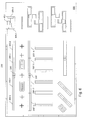
- Figure 4 represents schematically a top view of pieces of furniture and RFID electronic elements to illustrate an example of using a single RFID reader and the associated processing means to handle signals received by antennas of several pieces of furniture, for example several gondolas.
- the set 400-1 comprising pieces of furniture 200-1 to 200-4 (represented according to a top view) is associated with local processing system 230.
- the set 400-2 comprising pieces of furniture 200'-1 to 200'-4 is associated with local processing system 230'.
- local processing systems 230 and 230' are arranged within a piece of furniture, as illustrated with dashed lines, for example in a lower position of the third piece of furniture, that is to say approximately in the middle of the sets of pieces of furniture so as to optimize cabling.
- the local processing system is advantageously located in the middle of the pieces of furniture, as illustrated.
- Each piece of furniture 200-1 to 200-4 and 200'-1 to 200'-4 is similar to the piece of furniture 200 described by reference to Figures 2 and 3 . It comprises several antennas that can be accessed individually thanks to multiplexers.
- the multiplexers of the pieces of furniture 200-1 to 200-4 and 200'-1 to 200'-4 are connected, directly or indirectly, to the local processing systems 230 and 230', respectively, so that the local processing system 230 can transmit or receive data selectively via each antenna of the pieces of furniture 200-1 to 200-4 and that the local processing system 230' can transmit or receive data selectively via each antenna of the pieces of furniture 200'-1 to 200'-4.
- local processing systems 230 and 230' comprise a communication interface enabling the local processing systems to receive data from and/or transmit data to a central processing system 400.
- each of the local processing systems 230 and 230' comprises a software module capable of selecting each antenna of the pieces of furniture to which the local processing systems are connected, of transmitting interrogation requests and of receiving responses to the interrogation requests, enabling an inventory of RFID tags located in the vicinity of the antennas to be made.
- the results of the inventory operations are preferably stored locally in a memory of the local processing systems.
- a loop on each antenna of each pre-cabled module of each piece of furniture of a set of pieces of furniture is carried on regular period of time and/or on request.
- Central processing system 400 can be, for example, a server. It comprises a communication bus 405, a central processing unit 410 capable of executing instructions from program ROM 415 on powering up of the device, and instructions relating to a software application from main memory 420 after the powering up.
- the main memory 420 is for example of Random Access Memory (RAM) type which functions as a working area of CPU 410 via the communication bus 405, and the memory capacity thereof can be expanded by an optional RAM connected to an expansion port (not illustrated).
- Instructions relating to the software application may be loaded into the main memory 420 from a hard-disk (HD) 425 or the program ROM 415 for example.
- HD hard-disk
- Such a software application can be, in particular, a software application carrying out the steps described by reference to Figure 8b .
- Reference numeral 430 is a network interface that allows the device 400 to receive data from and/or to transmit data to other devices, in particular to local processing systems 230 and 230'.
- the device 400 can consist of one or more dedicated integrated circuits (ASICs).
- ASICs dedicated integrated circuits
- the central processing system interrogates the local processing systems at regular intervals of time and/or on request to obtain the results of the inventory operations carried out by the local processing system of each set of pieces of furniture or of some of the sets of pieces of furniture.
- a local processing system can be identified by an identifier such as an Ethernet identifier, an IP (Internet Protocol) address, or similar.
- the obtained results can be consolidated into one or more databases.
- Figure 5a illustrates a front view of the set of pieces of furniture 400-2 illustrated in Figure 4 .
- piece of furniture 200'-1 comprises pre-cabled modules 215"-11 and 215"-12 on the visible side.
- pieces of furniture 200'-2 and 200'-3 each comprise two pre-cabled modules while piece of furniture 200'-4 comprises three pre-cabled modules, on the visible side. Still for the sake of illustration, it is considered that both sides of each piece of furniture are similar to each other.
- Each antenna of the pieces of furniture can be identified by its position within its pre-cabled module, the position of the pre-cabled module in the piece of furniture, and the position of the piece of furniture in the set of pieces of furniture.
- theoretical indicia may be associated with the antennas, as illustrated, to define their positions.
- the position of an antenna is defined by an antenna position within a pre-cabled module, an offset, an elevation (or vertical position), and a side indication:
- Table 1 in the Appendix illustrates an example of several positions of the antennas illustrated in Figure 5 (the reference being the position of the RFID reader and the floor).
- positions can be stored in the corresponding local processing system, for example when the corresponding pieces of furniture are arranged within the facility. Storage of the positions can be carried out locally from the local processing systems or remotely using, for example, the central processing system.
- detection areas associated with antennas can be represented in representations of pieces of furniture, in particular if standard pre-cabled modules are used, for example pre-cabled modules having the same dimensions such as 400mm height and 1330mm width and if the position of the antennas are predetermined, for example arranged on a regular basis.
- the logical position of an antenna expressed as a function of a module position within a piece of furniture and of an antenna position within a module can be used to determine the physical position of the antenna within the piece of furniture.
- Figure 5b illustrates an example of representing the physical position of a detection area in a representation of the piece of furniture illustrated in Figure 2 . It is assumed that the pre-cabled modules of the piece of furniture are of the same dimensions and that the antennas are located at predetermined positions (arranged on a regular basis along the modules). For the sake of illustration, the height of the modules is equal to 400 mm and their width is equal to 1330 mm.
- the logical position of the detection area associated with antenna 220-12, which corresponds to the second antenna (from the left) of the third module (from the floor), in one side of the piece of furniture, is (2, 3).
- the detection area is comprised between the distances equal to 332.5mm (1330 / 4) and 665 mm (1330 / 2) from the left, and between the distances equal to 800 mm (400 x 2) and 1200 mm (400 x 3) from the floor, as represented.
- the piece of furniture 200 may be represented schematically, for example on a computer display, as illustrated with reference 500 (since the position of the antennas (represented here with dashed lines) are of no use to customers, they are preferably not represented).
- Figure 6 illustrates an example of a layout map of pieces of furniture in a facility.
- the layout map delimits the ground space 600 where pieces of furniture have to be arranged.
- pieces of furniture comprise, in particular, the set of pieces of furniture 200-1 to 200-4 associated with local processing system 230, the set of pieces of furniture 200'-1 to 200'-4 associated with local processing system 230', and the central processing system 400.
- the central processing system 400 is connected here to two graphical user interfaces 605-1 and 605-2 enabling a customer to localize an item in the facility.
- the layout map comprises representations of other pieces of furniture and of checkouts.
- Figure 7 illustrates an example of the definition of the positions of the RFID readers associated with the pieces of furniture illustrated in Figure 6 .
- the local processing systems are identified with an identifier Ri and coordinates (x, y, ⁇ ) where x and y represent the abscissa and the ordinate of the local processing system in a predetermined coordinate system such as coordinate system 700 and ⁇ represents the angle between the abscissa axis and the main longitudinal axis of the set of pieces of furniture associated with the local processing system.
- local processing system 230 can be identified with identifier R2 and the coordinates (x R2 , y R2 , 0).
- local processing system 705 associated with pieces of furniture extending along a vertical axis (according to the layout map) can be identified with identifier R6 and the coordinates ( x R6 , y R6 , 90) and local processing system 710, associated with pieces of furniture extending along a diagonal axis (still according to the layout map) can be identified with identifier R9 and the coordinates ( x R9 , y R9 , 45).
- Determining the positions of the pieces of furniture in a layout map can be done by an operator, can be done automatically by image analysis of the layout map and pattern recognition, or automatically in a computer-aided design application when the layout map is created.
- Knowing the relative position of a local processing system associated with a piece of furniture in view of the position of the latter makes it possible to calculate the position of the local processing system. Again, this can be done by an operator or automatically.
- coordinates of local processing systems can be expressed using the 'mks' system or as a function of the size of pieces of furniture which is standardized.
- the determined positions of the local processing systems can be stored in a memory of the central processing system. Combining the position of local processing system associated with a piece of furniture as defined in the layout map with the relative position of a specific antenna as a function of the position of the local processing system connected to this specific antenna makes it possible to calculate the position of the antenna in the layout map, that is to say in the facility.
- the position of an antenna used to localize an item searched for identified as a function of an RFID tag identifier to which it is attached can be displayed in conjunction with a layout map or a facility map to help someone in localizing this item.
- Figure 8 comprising Figures 8a and 8b , illustrates an example of steps carried out in one or several local processing systems and in a central processing system for localizing items in a facility, respectively.
- a first step is directed to initializing indexes i, j, and k to the value one (step 800).
- indexes are indexes of a piece of furniture associated with the local processing system, of a pre-cabled module in a piece of furniture associated with the local processing system, and of a position of an antenna in a pre-cabled module in a piece of furniture associated with the local processing system, respectively.
- step 805 is directed to identifying all the RFID tags that are located in the vicinity of the antenna located in the piece of furniture (PF) having index i (in the set of pieces of furniture associated with the local processing system carrying out the described steps), in the pre-cabled module (PCM) of that piece of furniture having index j , at the position (POS) k of that pre-cabled module.
- the multiplexers are set appropriately according to a predetermined table or predetermined rules.
- the obtained RFID tag identifiers are stored in relation with their local positions, that is to say, for example, with indexes i , j , and k, in a local database, for example in a table such as table 2 given in the Appendix.
- index k is incremented by one and a test is performed to determine whether or not the value of this index is greater than NBAnt ( PF[i],PCM[j] ) which represents the number of antennas in the pre-cabled module having index j of the piece of furniture having index i in the set of pieces of furniture associated with the local processing system carrying out the described steps (step 810).
- NBAnt PF[i],PCM[j]
- This value can be common to all pre-cabled modules or determined as a function of a pre-cabled module type.
- step 805 is repeated.
- index k is greater than NBAnt(PF[i],PCM[j])
- index j is incremented by one and a test is performed to determine whether or not the value of this index is greater than NBPCM(PF[i]) which represents the number of pre-cabled modules in the piece of furniture having index i in the set of pieces of furniture associated with the local processing system carrying out the described steps (step 815).
- NBPCM(PF[i]) represents the number of pre-cabled modules in the piece of furniture having index i in the set of pieces of furniture associated with the local processing system carrying out the described steps.
- This value can be common to all pieces of furniture associated with the local processing system carrying out the described steps or determined as a function of a type of pieces of furniture.
- step 805 is repeated.
- index j is greater than NBPCM(PF[i])
- index i is incremented by one and a test is performed to determine whether or not the value of this index is greater than NBPF which represents the number pieces of furniture in the set of pieces of furniture associated with the local processing system carrying out the described steps (step 820).
- step 805 If the value of index i is not greater than NBPF, step 805 is repeated. On the contrary, if the value of index i is greater than NBPF, the algorithm is branched to step 800 where indexes i, j, and k are reinitialized. As illustrated, a programmable timer can be used (step 825) so as to perform an RFID tag inventory on a periodic basis.
- step 830 is directed to determining whether a request for transmitting an RFID tag inventory, that is to say a list of RFID tag identifiers and associated local positions, has been received. Such a request is typically received from a central processing system.
- the RFID tag identifiers and their local positions as determined in step 805 are transmitted to the system at the origin of the request or to a system that can be identified from the request (step 835).
- the algorithm is branched to step 830 to process a following request.
- all the RFID tag identifiers and the associated local positions can be transmitted or, alternatively, only the new identified RFID tag identifiers and their local positions and the RFID tag identifiers that have been previously identified but that are no more detected can be transmitted.
- the choice can be done as a function of an indication received in the request.
- local positions can consist in a set of indexes of a piece of furniture, of a pre-cabled module, and of an antenna. It can also consist in coordinates determined in a predetermined coordinate system, for example a coordinate system centered on the local processing system, in the mks system, or centered on the local processing system, in a system expressed as a function of the size of pieces of furniture that is standardized.
- a first step is directed to initialize index i to the value one (step 850).
- Index i is an index of the local processing systems that enable an RFID tag inventory to be carried out.
- an inventory request is sent to the local processing system (LPS) having index i.
- the central processing system receives a set of RFID tag identifiers and local positions that are stored in a tag database (TagDB) along with an identifier of the current selected local processing system (LPS[i]).
- index i is incremented by one and a test is performed to determine whether or not the value of this index is greater than NBLPS that represents the number of local processing systems that can carry out an RFID tag inventory (step 860). This value can be determined in a configuration step.
- step 855 If the value of index i is not greater than NBLPS, step 855 is repeated. On the contrary, if index i is greater than NBLPS, algorithm is branched to step 850 where index i is reinitialized. As illustrated, a programmable timer can be used (step 865) so as to perform an RFID tag inventory on a periodic basis.
- step 870 is directed to determining whether a request for determining the position of an item associated with a tag is received. Such a request is typically received from a user via a graphical user's interface or from a remote processing system.
- the RFID tag identifier corresponding to the searched item is obtained (step 875). It can be obtained from a product database that is used, in particular, to establish a link between each product and each tag identifier, the product identifier and the RFID tag identifier being advantageously the same.
- a local position and a local processing system identifier are obtained from the tag database (step 880).
- the RFID tag identifier is equal to 2431, it can be determined from table 3 of the Appendix that this RFID tag has been identified by the antenna located at the second position of a pre-cabled module also located at the second position of a piece of furniture located at the first position of a set of pieces of furniture associated with the local processing system which identifier is equal to 1.
- the position of the local processing system whose identifier corresponds to the obtained local processing system identifier is obtained (step 885).
- LPSID local processing system identifier
- the position of the RFID tag corresponding to the item searched for is determined as a function of the obtained local position and of the position of the local processing system and transmitted to the requester (step 890).
- the position of an antenna can be expressed using logical values (relative position of an antenna within a module, relative position of a module within a set of modules, relative position of piece of furniture within a set of pieces of furniture, side of piece of furniture), these logical position values being converted into real position values according to the characteristics of the pre-cabled modules and of the pieces of furniture for determining the position of an item in a set of pieces of furniture.
- step 870 After the position of the searched item has been determined and transmitted, the algorithm is branched to step 870 to process a following request.
- a floor level can be added to a table used to store positions of antennas (for example Table 1 in the Appendix) and to a local database used to store antenna positions and identified tag identifiers (for example Table 1 in the Appendix).
- a local processing system can be identified with an identifier Ri and coordinates (x, y, level, ⁇ ) where level represents the floor level of the local processing system.
- Such a floor level parameter is particularly useful for retail areas that are spread over several floor levels.
- the granularity of searched positions may be different from the one described above. Indeed, if the searched positions of items can be determined as an RFID antenna level, they can also be determined as a pre-cabled module level, at a side of piece of furniture level, and so on.
- Figure 9 is an illustration of a context of implementation of embodiments of the invention. This context of implementation may be particularly suited for brand operating marketing campaigns in stores and supermarket by providing smart gondolas with products to be advertised. Generally, such gondolas are directly managed by the brand and not the store or the supermarket in which it is disposed.
- a plurality of facilities (FACILITY-1, ..., FACILITY-P) store items in respective pieces of furniture.
- each set of pieces of furniture has a local processing system to which are connected antennas for detecting radio frequency tags attached to the items.
- facility 900 (FACILITY-1) comprise a plurality of local processing systems
- PROC SYST 230-1, .., 230-2 and facility 901(FACILITY-P) comprise a plurality of local processing systems (PROC SYST) 230-M, .., 230-Q).
- Facility 900 comprises a central processing unit 400-1 and facility 901 comprises a central processing unit 400-P.
- each piece of furniture the antennas are configured to detect radio frequency tags disposed in their respective vicinity. Also, each local processing system of each set of pieces of furniture is configured to determine the localization of each item disposed in the piece of furniture.
- each local processing system may determine the number of items stored in the pieces of furniture of the set to which it corresponds.
- the local processing system may determine the number of items for each type.
- the central processing units may determine in each facility, the total number of items in the facility.
- the local processing systems may regularly transmit the number of items they store.
- the central processing unit may also send requests for obtaining the information.
- the central processing unit of each facility is configured to communicate with a stock management system 903 (STCK MANGMNT SYST), through a communication network 902 (NET).
- the communication network may be a public network such as the Internet or the telephone network (for example a GSM or 3G network).
- the central processing units may transmit stock information to the stock management system.
- the stock information contains a total number of items stored in the facility.
- the stock information may also contain a number of items needed in the facility (a target number of items to be present in the facility may be defined).
- the stock information may contain any other information needed by the stock management system for determining how to provide the facility with new items.
- local processing systems may be configured to act as the central processing system. Thus, there is no need for an additional device.
- the stock management system may trigger the provision. For example, it may generate a list 1005 of the facilities at which items should be delivered as described with reference to Figure 10 .
- the list comprises a column 1000 indicating the order of delivery.
- the stock management system may determine, based on the localization of each facility, in what order to deliver the items to them so as to save time.
- Another column 1001 indicates the identification of the facility, a column 1002 indicates the geographical localization of the facility, a column 1003 indicates the type of items to deliver and a column 1004 the number of items.
- the localization of the items in the pieces of furniture can be determined by comparing a current inventory with an initial inventory. In order to help the delivery man to fill the pieces of furniture, he may also be provided with indications on the localization of the piece of furniture in the facility and the localization in the piece of furniture where to place the items. This additional information can be provided in the list 1005 or in another document generated by the stock management system.
- the stock information transmitted by the central processing units may be enriched with data relating to the localization of the items, in addition to the number of items needed or present in the pieces of furniture.
- Figure 11 is a general flowchart of steps of a method performed for managing stocks according to embodiments.
- step 1100 it is determined during step 1100 whether the number of items in a facility should be updated.
- the update may be triggered regularly or upon request. For example, each processing system in each piece of furniture triggers the update. However, the update may also be triggered by the central processing unit of the facility.
- variable i is set to 1 and the number of items in piece of furniture PF(i) is determined during step 1102. In case the total number NBPF of pieces of furniture is not reached by variable i (test 1103), the variable is incremented (step 1108) and the number of items is determined in the next pieces of furniture.
- the total number of items in the facility is determined during step 1104. This total number may be calculated by the central processing unit, based on results provided by each processing system in the pieces of furniture.
- stock information is generated by the central processing unit during step 1005.
- the stock information may contain a variety of data such as a number of items needed, their respective locations in the facility and/or in the pieces of furniture.
- the stock information may be transmitted on a regular basis.
- the stock information may also be transmitted upon request of the stock management system and a request message may be awaited.
- the stock information is then transmitted during step 1107.
- the stock information may be used for aggregating statistical data concerning the sales of products.
- the stock management system may know in advance if more or less quantities of particular product should be ordered in the future.
Landscapes
- Business, Economics & Management (AREA)
- Economics (AREA)
- Engineering & Computer Science (AREA)
- Marketing (AREA)
- Quality & Reliability (AREA)
- Finance (AREA)
- Entrepreneurship & Innovation (AREA)
- Human Resources & Organizations (AREA)
- Accounting & Taxation (AREA)
- Operations Research (AREA)
- Development Economics (AREA)
- Strategic Management (AREA)
- Tourism & Hospitality (AREA)
- Physics & Mathematics (AREA)
- General Business, Economics & Management (AREA)
- General Physics & Mathematics (AREA)
- Theoretical Computer Science (AREA)
Priority Applications (1)
| Application Number | Priority Date | Filing Date | Title |
|---|---|---|---|
| EP14305208.2A EP2908276A1 (de) | 2014-02-14 | 2014-02-14 | Verwaltung von in Möbelstücken in Gebäuden aufbewahrten Artikelbeständen |
Applications Claiming Priority (1)
| Application Number | Priority Date | Filing Date | Title |
|---|---|---|---|
| EP14305208.2A EP2908276A1 (de) | 2014-02-14 | 2014-02-14 | Verwaltung von in Möbelstücken in Gebäuden aufbewahrten Artikelbeständen |
Publications (1)
| Publication Number | Publication Date |
|---|---|
| EP2908276A1 true EP2908276A1 (de) | 2015-08-19 |
Family
ID=50189643
Family Applications (1)
| Application Number | Title | Priority Date | Filing Date |
|---|---|---|---|
| EP14305208.2A Ceased EP2908276A1 (de) | 2014-02-14 | 2014-02-14 | Verwaltung von in Möbelstücken in Gebäuden aufbewahrten Artikelbeständen |
Country Status (1)
| Country | Link |
|---|---|
| EP (1) | EP2908276A1 (de) |
Cited By (1)
| Publication number | Priority date | Publication date | Assignee | Title |
|---|---|---|---|---|
| EP3748592A1 (de) * | 2019-06-07 | 2020-12-09 | Kemas GmbH | Warenspeicher |
Citations (3)
| Publication number | Priority date | Publication date | Assignee | Title |
|---|---|---|---|---|
| EP2597595A1 (de) | 2011-11-24 | 2013-05-29 | HMY Group | Multiplexer-System und Verfahren zur Auswahl einer Antenne in einem vorverkabelten Modul mit eingebetteten Patch-Antennen für Möbel |
| EP2597594A1 (de) | 2011-11-24 | 2013-05-29 | HMY Group | Vorverkabeltes Modul mit eingebetteten Patch-Antennen für Möbel |
| EP2597593A1 (de) | 2011-11-24 | 2013-05-29 | HMY Group | Verbesserte Struktur einer Patch-Antenne für Möbel |
-
2014
- 2014-02-14 EP EP14305208.2A patent/EP2908276A1/de not_active Ceased
Patent Citations (3)
| Publication number | Priority date | Publication date | Assignee | Title |
|---|---|---|---|---|
| EP2597595A1 (de) | 2011-11-24 | 2013-05-29 | HMY Group | Multiplexer-System und Verfahren zur Auswahl einer Antenne in einem vorverkabelten Modul mit eingebetteten Patch-Antennen für Möbel |
| EP2597594A1 (de) | 2011-11-24 | 2013-05-29 | HMY Group | Vorverkabeltes Modul mit eingebetteten Patch-Antennen für Möbel |
| EP2597593A1 (de) | 2011-11-24 | 2013-05-29 | HMY Group | Verbesserte Struktur einer Patch-Antenne für Möbel |
Cited By (1)
| Publication number | Priority date | Publication date | Assignee | Title |
|---|---|---|---|---|
| EP3748592A1 (de) * | 2019-06-07 | 2020-12-09 | Kemas GmbH | Warenspeicher |
Similar Documents
| Publication | Publication Date | Title |
|---|---|---|
| US6736316B2 (en) | Inventory control and indentification method | |
| US6927692B1 (en) | RF inventory system | |
| US20040099735A1 (en) | Inventory control and identification method | |
| CN101689256B (zh) | 用于控制库存和货架存货的多方向rfid读取器 | |
| JP4286838B2 (ja) | 情報技術(it)機器測位システム | |
| RU2750097C2 (ru) | Способ обнаружения электронных ценников в торговом зале | |
| US20100201520A1 (en) | System for determining item location based on feedback from fixed radio frequency identification (rfid) readers and/or fixed rfid beacon tags | |
| CA2894675C (en) | Self-optimizing method of and system for efficiently deploying radio frequency identification (rfid) tag readers in a controlled area containing rfid-tagged items to be monitored | |
| US20100201488A1 (en) | Displaying radio frequency identification (rfid) read range of an rfid reader based on feedback from fixed rfid beacon tags | |
| CN104981825A (zh) | 缺货传感器 | |
| JP6675002B2 (ja) | 商品と位置との間の関連付けデータを更新する方法 | |
| TWI419053B (zh) | 射頻辨識標籤監控系統及監控其標籤物品存在空間的方法 | |
| JP6256465B2 (ja) | 物品管理システム、物品管理方法及び物品管理プログラム | |
| EP1049042A1 (de) | Speichersystem | |
| US9652647B2 (en) | Article management system, article management method, and non-transitory computer readable medium storing article management program | |
| JP2003044562A (ja) | 在庫管理システム及び方法 | |
| US20080204224A1 (en) | Path tracking system, terminal device, fixed communication device, and path management device | |
| US11995500B2 (en) | Method for locating an electronic shelf label | |
| EP2908275A1 (de) | Verfahren, Vorrichtung und Computerprogramm zur Lokalisierung von Funkfrequenzetiketten in Möbelstücken im Inneren von Gebäuden | |
| EP2908276A1 (de) | Verwaltung von in Möbelstücken in Gebäuden aufbewahrten Artikelbeständen | |
| US20080243647A1 (en) | Product management system and product management method | |
| CN113382358B (zh) | 一种基于超宽带技术的资产定位方法、装置 | |
| EP2908265A1 (de) | Konfigurierbares Möbelstück mit adaptivem Hochfrequenzetikettleser und Verfahren zur Auswahl der Antennen in solch einem Möbelstück | |
| CN106785331A (zh) | 应用于黄金珠宝行业的线极化近场天线的智能柜台系统 | |
| CN112862030B (zh) | 商品对象陈列信息跟踪控制方法、装置及系统 |
Legal Events
| Date | Code | Title | Description |
|---|---|---|---|
| PUAI | Public reference made under article 153(3) epc to a published international application that has entered the european phase |
Free format text: ORIGINAL CODE: 0009012 |
|
| AK | Designated contracting states |
Kind code of ref document: A1 Designated state(s): AL AT BE BG CH CY CZ DE DK EE ES FI FR GB GR HR HU IE IS IT LI LT LU LV MC MK MT NL NO PL PT RO RS SE SI SK SM TR |
|
| AX | Request for extension of the european patent |
Extension state: BA ME |
|
| 17P | Request for examination filed |
Effective date: 20150819 |
|
| RBV | Designated contracting states (corrected) |
Designated state(s): AL AT BE BG CH CY CZ DE DK EE ES FI FR GB GR HR HU IE IS IT LI LT LU LV MC MK MT NL NO PL PT RO RS SE SI SK SM TR |
|
| STAA | Information on the status of an ep patent application or granted ep patent |
Free format text: STATUS: EXAMINATION IS IN PROGRESS |
|
| 17Q | First examination report despatched |
Effective date: 20180817 |
|
| STAA | Information on the status of an ep patent application or granted ep patent |
Free format text: STATUS: EXAMINATION IS IN PROGRESS |
|
| STAA | Information on the status of an ep patent application or granted ep patent |
Free format text: STATUS: THE APPLICATION HAS BEEN REFUSED |
|
| 18R | Application refused |
Effective date: 20201214 |