EP2907685A1 - Vehicle accelerator pedal apparatus - Google Patents
Vehicle accelerator pedal apparatus Download PDFInfo
- Publication number
- EP2907685A1 EP2907685A1 EP13895100.9A EP13895100A EP2907685A1 EP 2907685 A1 EP2907685 A1 EP 2907685A1 EP 13895100 A EP13895100 A EP 13895100A EP 2907685 A1 EP2907685 A1 EP 2907685A1
- Authority
- EP
- European Patent Office
- Prior art keywords
- pedal
- housing
- arm
- side arm
- force
- Prior art date
- Legal status (The legal status is an assumption and is not a legal conclusion. Google has not performed a legal analysis and makes no representation as to the accuracy of the status listed.)
- Granted
Links
Images


Classifications
-
- B—PERFORMING OPERATIONS; TRANSPORTING
- B60—VEHICLES IN GENERAL
- B60K—ARRANGEMENT OR MOUNTING OF PROPULSION UNITS OR OF TRANSMISSIONS IN VEHICLES; ARRANGEMENT OR MOUNTING OF PLURAL DIVERSE PRIME-MOVERS IN VEHICLES; AUXILIARY DRIVES FOR VEHICLES; INSTRUMENTATION OR DASHBOARDS FOR VEHICLES; ARRANGEMENTS IN CONNECTION WITH COOLING, AIR INTAKE, GAS EXHAUST OR FUEL SUPPLY OF PROPULSION UNITS IN VEHICLES
- B60K26/00—Arrangements or mounting of propulsion unit control devices in vehicles
- B60K26/02—Arrangements or mounting of propulsion unit control devices in vehicles of initiating means or elements
- B60K26/021—Arrangements or mounting of propulsion unit control devices in vehicles of initiating means or elements with means for providing feel, e.g. by changing pedal force characteristics
-
- F—MECHANICAL ENGINEERING; LIGHTING; HEATING; WEAPONS; BLASTING
- F02—COMBUSTION ENGINES; HOT-GAS OR COMBUSTION-PRODUCT ENGINE PLANTS
- F02D—CONTROLLING COMBUSTION ENGINES
- F02D11/00—Arrangements for, or adaptations to, non-automatic engine control initiation means, e.g. operator initiated
- F02D11/04—Arrangements for, or adaptations to, non-automatic engine control initiation means, e.g. operator initiated characterised by mechanical control linkages
-
- B—PERFORMING OPERATIONS; TRANSPORTING
- B60—VEHICLES IN GENERAL
- B60K—ARRANGEMENT OR MOUNTING OF PROPULSION UNITS OR OF TRANSMISSIONS IN VEHICLES; ARRANGEMENT OR MOUNTING OF PLURAL DIVERSE PRIME-MOVERS IN VEHICLES; AUXILIARY DRIVES FOR VEHICLES; INSTRUMENTATION OR DASHBOARDS FOR VEHICLES; ARRANGEMENTS IN CONNECTION WITH COOLING, AIR INTAKE, GAS EXHAUST OR FUEL SUPPLY OF PROPULSION UNITS IN VEHICLES
- B60K26/00—Arrangements or mounting of propulsion unit control devices in vehicles
- B60K26/02—Arrangements or mounting of propulsion unit control devices in vehicles of initiating means or elements
-
- F—MECHANICAL ENGINEERING; LIGHTING; HEATING; WEAPONS; BLASTING
- F02—COMBUSTION ENGINES; HOT-GAS OR COMBUSTION-PRODUCT ENGINE PLANTS
- F02D—CONTROLLING COMBUSTION ENGINES
- F02D11/00—Arrangements for, or adaptations to, non-automatic engine control initiation means, e.g. operator initiated
- F02D11/02—Arrangements for, or adaptations to, non-automatic engine control initiation means, e.g. operator initiated characterised by hand, foot, or like operator controlled initiation means
-
- G—PHYSICS
- G05—CONTROLLING; REGULATING
- G05G—CONTROL DEVICES OR SYSTEMS INSOFAR AS CHARACTERISED BY MECHANICAL FEATURES ONLY
- G05G1/00—Controlling members, e.g. knobs or handles; Assemblies or arrangements thereof; Indicating position of controlling members
- G05G1/30—Controlling members actuated by foot
- G05G1/40—Controlling members actuated by foot adjustable
- G05G1/405—Controlling members actuated by foot adjustable infinitely adjustable
-
- G—PHYSICS
- G05—CONTROLLING; REGULATING
- G05G—CONTROL DEVICES OR SYSTEMS INSOFAR AS CHARACTERISED BY MECHANICAL FEATURES ONLY
- G05G1/00—Controlling members, e.g. knobs or handles; Assemblies or arrangements thereof; Indicating position of controlling members
- G05G1/30—Controlling members actuated by foot
- G05G1/44—Controlling members actuated by foot pivoting
-
- G—PHYSICS
- G05—CONTROLLING; REGULATING
- G05G—CONTROL DEVICES OR SYSTEMS INSOFAR AS CHARACTERISED BY MECHANICAL FEATURES ONLY
- G05G5/00—Means for preventing, limiting or returning the movements of parts of a control mechanism, e.g. locking controlling member
- G05G5/03—Means for enhancing the operator's awareness of arrival of the controlling member at a command or datum position; Providing feel, e.g. means for creating a counterforce
-
- B—PERFORMING OPERATIONS; TRANSPORTING
- B60—VEHICLES IN GENERAL
- B60K—ARRANGEMENT OR MOUNTING OF PROPULSION UNITS OR OF TRANSMISSIONS IN VEHICLES; ARRANGEMENT OR MOUNTING OF PLURAL DIVERSE PRIME-MOVERS IN VEHICLES; AUXILIARY DRIVES FOR VEHICLES; INSTRUMENTATION OR DASHBOARDS FOR VEHICLES; ARRANGEMENTS IN CONNECTION WITH COOLING, AIR INTAKE, GAS EXHAUST OR FUEL SUPPLY OF PROPULSION UNITS IN VEHICLES
- B60K26/00—Arrangements or mounting of propulsion unit control devices in vehicles
- B60K26/02—Arrangements or mounting of propulsion unit control devices in vehicles of initiating means or elements
- B60K26/021—Arrangements or mounting of propulsion unit control devices in vehicles of initiating means or elements with means for providing feel, e.g. by changing pedal force characteristics
- B60K2026/022—Arrangements or mounting of propulsion unit control devices in vehicles of initiating means or elements with means for providing feel, e.g. by changing pedal force characteristics with tactile feedback from a controller, e.g. vibrations
-
- B—PERFORMING OPERATIONS; TRANSPORTING
- B60—VEHICLES IN GENERAL
- B60K—ARRANGEMENT OR MOUNTING OF PROPULSION UNITS OR OF TRANSMISSIONS IN VEHICLES; ARRANGEMENT OR MOUNTING OF PLURAL DIVERSE PRIME-MOVERS IN VEHICLES; AUXILIARY DRIVES FOR VEHICLES; INSTRUMENTATION OR DASHBOARDS FOR VEHICLES; ARRANGEMENTS IN CONNECTION WITH COOLING, AIR INTAKE, GAS EXHAUST OR FUEL SUPPLY OF PROPULSION UNITS IN VEHICLES
- B60K26/00—Arrangements or mounting of propulsion unit control devices in vehicles
- B60K26/02—Arrangements or mounting of propulsion unit control devices in vehicles of initiating means or elements
- B60K26/021—Arrangements or mounting of propulsion unit control devices in vehicles of initiating means or elements with means for providing feel, e.g. by changing pedal force characteristics
- B60K2026/023—Arrangements or mounting of propulsion unit control devices in vehicles of initiating means or elements with means for providing feel, e.g. by changing pedal force characteristics with electrical means to generate counter force or torque
-
- Y—GENERAL TAGGING OF NEW TECHNOLOGICAL DEVELOPMENTS; GENERAL TAGGING OF CROSS-SECTIONAL TECHNOLOGIES SPANNING OVER SEVERAL SECTIONS OF THE IPC; TECHNICAL SUBJECTS COVERED BY FORMER USPC CROSS-REFERENCE ART COLLECTIONS [XRACs] AND DIGESTS
- Y10—TECHNICAL SUBJECTS COVERED BY FORMER USPC
- Y10T—TECHNICAL SUBJECTS COVERED BY FORMER US CLASSIFICATION
- Y10T74/00—Machine element or mechanism
- Y10T74/20—Control lever and linkage systems
- Y10T74/20528—Foot operated
- Y10T74/20534—Accelerator
Abstract
Description
- The present invention relates to an improvement in a vehicle accelerator device provided with a reaction-force-applying mechanism for applying a reaction force to a pedal-side arm that a driver depresses.
- Vehicle accelerator devices provided with reaction-force-applying mechanisms have been known, e.g. in
Patent Document 1, in which a reaction force is applied to a pedal-side arm from a reaction-force-applying mechanism in accordance with an amount by which the pedal-side arm is depressed or other information. - The vehicle accelerator device known in
Patent Document 1 includes a housing mounted on a vehicle body, a pedal-side arm pivotably supported in the housing, a pad provided on a lower end of the pedal-side arm and used for depressing the pedal-side arm, and a reaction-force-applying mechanism for applying a reaction force to the pedal-side arm. The pedal-side arm extends downward from the housing. The reaction-force-applying mechanism is disposed between the housing positioned above and the pad positioned below, and is incorporated into the housing. The reaction-force-applying mechanism includes a motor for generating the reaction force, a reduction gear for reducing the rotational speed of the motor, and a motor-side arm mounted on an output shaft of the reduction gear. The motor-side arm is a member for applying the reaction force generated by the motor to the pedal-side arm. - A brake pedal is proximal to the accelerator device. Depending on the type of vehicle, the accelerator device may be disposed near the wheel house of a front wheel. Therefore, the accelerator device needs to be able to be easily disposed in a non-interfering manner even when the device is laterally proximal to the wheel house or the brake pedal. Specifically, a high degree of freedom is required in regard to where the accelerator device is to be disposed.
- However, because the motor and the reduction gear of the reaction-force-applying mechanism are connected in a lateral or vehicle width direction, the size of the reaction-force-applying mechanism is large in the vehicle width direction. Therefore, the entire accelerator device has a large size in the vehicle width direction. In addressing this situation, it has been suggested that the lateral size of the reaction-force-applying mechanism be reduced; however, merely reducing the width of the reaction-force-applying mechanism results in complicating the configuration of the reaction-force-applying mechanism. Accordingly, there is scope for improvement.
- Patent Document 1: International Publication (WO-A) No.
2012/029503 - The present invention seeks to provide a technique which is capable of enhancing the degree of freedom in arranging a vehicle accelerator device provided with a reaction-force-applying mechanism.
- According to a first aspect of the present invention, there is provided a vehicle accelerator device comprising a housing mountable on a vehicle body, a pedal-side arm pivotably supported by a support shaft in the housing for undergoing pivotal movement in a front-rear direction of the vehicle body, a depressible pad provided on the pedal-side arm, and a reaction-force-applying mechanism for applying a reaction force to the pedal-side arm against a depressing force applied to the pad, the reaction-force-applying mechanism comprising a drive source for generating the reaction force and a transmitting member for transmitting the reaction force generated by the drive source to the pedal-side arm, wherein the vehicle accelerator device is characterized in that: the reaction-force-applying mechanism is disposed above the housing; the pedal-side arm has an extension part extending to a side opposite the pad, across the support shaft, and from the pedal-side arm toward the transmitting member; and the extension part comes into contact with the transmitting member when the reaction force is received from the transmitting member.
- According to a second aspect of the present invention, preferably, the reaction-force-applying mechanism is set apart from the housing, and is mounted on the vehicle body so as to be separate from the housing; and only the extension part of the pedal-side arm comes into contact with the transmitting member.
- According to a third aspect of the present invention, preferably, the pedal-side arm comprises a first arm part pivotably supported in the housing by the support shaft for undergoing pivotal movement in the front-rear direction of the vehicle body and a second arm part positioned outside of the housing and provided on the first arm part; and the pad and the extension part are provided on the second arm part.
- According to a fourth aspect of the present invention, preferably, the pad is disposed so as to be able to be adjacent to a brake pedal in a vehicle width direction; the second arm part comprises a mounting part mounted to a lateral side surface of the first arm part and a bent part bending from the mounting part to a side laterally opposite the brake pedal; and the pad is provided on the bent part.
- According to a fifth aspect of the present invention, preferably, a gap is present at a position where the housing and the extension part are closest when the pedal-side arm pivots between an initial position at which the pad is not depressed and a maximum-depression position at which the pad is depressed by a maximum amount; and the second arm part is disposed in relation to the housing such that the gap decreases in correspondence with the pivoting of the pedal-side arm from the initial position toward the maximum-depression position.
- According to a sixth aspect of the present invention, preferably, the position of the pedal-side arm closest to the housing and the extension part when positioned at the initial position is on an upper edge of the housing; and
the extension part has a slanting part slanting toward the housing while extending above the upper edge of the housing. - According to a seventh aspect of the present invention, preferably, an arm proximal end part provided on the first arm part and supported by the support shaft is accommodated inside the housing; a distal end part of the first arm part is exposed to the outside through an opening in the housing; the second arm part comprises a mounting part mounted to a lateral side surface of the first arm part and a curved part curving so as to separate laterally from a side edge of the opening the mounting part is disposed below the opening; and the curved part is disposed across the side edge of the opening.
- According to an eighth aspect of the present invention, preferably, the drive source comprises an electric motor for generating the reaction force and a reduction gear for reducing a rotational speed of the electric motor and outputting the reduced speed; the transmitting member is connected to an output shaft of the reduction gear and is configured by a motor-side arm for transmitting the reaction force to the pedal-side arm; the reaction-force-applying mechanism has a bracket for supporting the electric motor and the reduction gear; and the bracket has a cable guard extending outward and upward of a range in which the motor-side arm can pivot and move.
- According to a ninth aspect of the present invention, preferably, an outer circumference and an upper side of the electric motor are covered by a heat-blocking cover for blocking at least part of heat generated by the electric motor.
- According to the first aspect of the invention, the reaction-force-applying mechanism for applying reaction force to the pedal-side arm is disposed above a housing in which the pedal-side arm is supported by the support shaft. Specifically, because a unit composed of the housing and the pedal-side arm supported in the housing does not include the reaction-force-applying mechanism, the unit has a small size in the lateral or vehicle width direction. The unit, being of small width, can be easily disposed in a non-interfering manner even when the unit is laterally proximal to a wheel house or a brake pedal. However, the reaction-force-applying mechanism includes the drive source for generating reaction force and the transmitting member for transmitting the reaction force generated by the drive source to the pedal-side arm, and therefore has larger lateral size than the unit. The reaction-force-applying mechanism, being of large width, is disposed above the housing of the unit, which is of small width. For example, the reaction-force-applying mechanism can be disposed above the wheel house or the pad of the brake pedal, thereby preventing interference therebetween.
- The lateral size of the portion of the vehicle accelerator device closest to the wheel house or the brake pedal in the lateral direction, specifically the lateral size of the unit, can thus be reduced as much as possible. The accelerator device, being of small width, can be easily disposed without any interference with the wheel house, the brake pedal, or other members positioned in the lateral vicinity of the accelerator device. The degree of freedom in arranging the accelerator device in the vehicle is enhanced.
- The pedal-side arm has the extension part extending to a side opposite the pad, across the support shaft, and from the pedal-side arm toward the transmitting member of the reaction-force-applying mechanism. The extension part comes into contact with the transmitting member when the reaction force is received from the transmitting member. Therefore, the configuration of the reaction-force-applying mechanism can be kept simple despite having the reaction-force-applying mechanism disposed above the housing. The accelerator device can therefore be obtained at low cost.
- According to the second aspect of the invention, the transmitting member of the reaction-force-applying mechanism comes into contact with only the extension part, whereby the reaction-force-applying mechanism can apply the reaction force to the pedal-side arm. Moreover, the reaction-force-applying mechanism is set apart from the housing, and is mounted on the vehicle body so as to be separate from the housing. Therefore, each of the housing and the reaction-force-applying mechanism can be mounted on the vehicle body in respectively desired locations. Therefore, an even larger degree of freedom can be used in regard to where to dispose the vehicle accelerator device in the vehicle.
- According to the third aspect of the invention, the pedal-side arm includes the first arm part pivotably supported in the housing by the support shaft for undergoing pivotal movement in the front-rear direction of the vehicle body, and the second arm part positioned outside of the housing and provided on the first arm part. Therefore, it is possible to determine whether or not the second arm part should be present according to, e.g., whether the reaction-force-applying mechanism is present. In a first case in which the vehicle accelerator device is not provided with the reaction-force-applying mechanism, it is possible to use only the first arm part without using the second arm part. In a second case in which the vehicle accelerator device is provided with the reaction-force-applying mechanism, the second arm part provided with the pad and the extension part is made available and is provided on the first arm part. In both the first case and the second case, the housing and an inner mechanism built into the housing can be jointly used. The accelerator device can therefore be obtained at low cost.
- According to the fourth aspect of the invention, the second arm part is mounted on the lateral side surface of the first arm part. Therefore, the second arm part can be easily mounted on the first arm part without contact being made with the housing. The second arm part also has the bent part bending from the mounting part mounted on the first arm part to the side laterally opposite the brake pedal, the pad being provided to the bent part. Therefore, the vehicle accelerator device can be easily disposed while interference with the brake pedal positioned in the lateral vicinity of the accelerator device is sufficiently avoided.
- According to the fifth aspect of the invention, the gap at the position where the extension part is closest to the housing decreases in correspondence with the pivoting of the pedal-side arm from the initial position at which the pedal-side arm is not depressed toward the maximum-depression position. Specifically, the gap when the pedal-side arm is in the initial position is larger than the gap when the pad is depressed. Even if some foreign object gets sandwiched between the housing and the extension part, specifically in the gap, while the pad is being depressed, the gap can be increased by releasing the step-on or depressing operation (returning the pedal-side arm to the initial position). As a result, the foreign object falls out of the gap. By thus releasing the depressing operation, the pedal-side arm is allowed to return to the initial position without any adverse effect caused by the foreign object.
- According to the sixth aspect of the invention, the extension part is closest to the upper edge of the housing when the pedal-side arm is positioned at the initial position. The extension part has a slanting part slanting toward the housing while extending above the upper edge of the housing. The slanting part approaches the housing in correspondence with the pivoting of the pedal-side arm from the initial position toward the maximum-depression position. Therefore, the gap at the position where the extension part is closest to the upper edge of the housing is decreased in size. The slanting part then separates from the housing in correspondence with the returning of the pedal-side arm from the maximum-depression position to the initial position. The gap at the position where the extension part is closest to the upper edge of the housing is increased in size. Therefore, sandwiching of a foreign object in a direction in which the pedal-side arm returns from the maximum-depression position to the initial position can be minimized.
- According to the seventh aspect of the invention, the second arm part has the mounting part mounted to the lateral side surface of the first arm part and the curved part curving so as to separate laterally from the side edge of the opening in the housing. The mounting part is disposed below the opening. The curved part is disposed across the side edge of the opening. Therefore, the gap between the housing and the second arm part can be increased in size at the position where the second arm part is disposed across the side edge of the opening. Sandwiching of the foreign object in the gap in the vicinity of the opening can therefore be minimized.
- According to the eighth aspect of the invention, the reaction-force-applying mechanism includes the bracket for supporting the electric motor and the reduction gear. Harnesses, cables, or other types of wires used for other devices often pass around the reaction-force-applying mechanism mounted on the vehicle. In response, the bracket has the cable guard extending outward and upward of a range in which the motor-side arm can pivot and move. The pivoting motor-side arm can be protected by the cable guard so as not to come into contact with the wires.
- According to the ninth aspect of the invention, the outer circumference and the upper side of the electric motor are covered by the heat-blocking cover for blocking at least part of heat generated by the electric motor. Therefore, it is possible to block the heat using the heat-blocking cover so that the heat generated by the electric motor does not affect the harnesses, cables, or other types of wires.
-
-
FIG. 1 is a view of a configuration in which a vehicle accelerator device according to the present invention is mounted on a vehicle body, seen from the pad-depressing direction; -
FIG. 2 is an enlarged view of the vehicle accelerator device shown inFIG. 1 ; -
FIG. 3 is a right side view of the vehicle accelerator device shown inFIG. 2 ; -
FIG. 4 is a perspective view of an accelerator pedal unit shown inFIG. 2 , seen from the upper-left; -
FIG. 5 is an enlarged view of the accelerator pedal unit shown inFIG. 2 ; -
FIG. 6 is a left side view of the accelerator pedal unit shown inFIG. 5 ; -
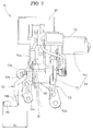
FIG. 7 is an enlarged view of a reaction-force-applying mechanism shown inFIG. 2 ; -
FIG. 8 is a left side view of the reaction-force-applying mechanism shown inFIG. 7 ; -
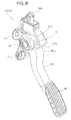
FIG. 9 is a perspective view of an example of a replacement for the pedal-side arm of the accelerator pedal unit shown inFIG. 4 ; and -
FIGS. 10(a) and 10(b) are diagrammatical views illustrating a change in the gap between an upper edge of a housing and an extension part shown inFIG. 5 . - A certain preferred embodiment of the present invention will be described below with reference to the accompanying sheets of drawings.
- A vehicle accelerator device according to the preferred embodiment will now be described. As shown in
FIGS. 1 through 3 , avehicle 10 takes the form of, e.g. a passenger vehicle, and is provided with avehicle braking device 20 and avehicle accelerator device 30. The twodevices passenger compartment 11, and are mounted on avehicle body 12, e.g. alower dashboard panel 13. - The
vehicle braking device 20 is disposed on a laterally inward side. Thevehicle accelerator device 30 is disposed on a laterally outward side and is adjacent to awheel house 14 for a front wheel. Specifically, thevehicle accelerator device 30 is adjacent to thevehicle braking device 20. - The vehicle accelerator device 30 (hereinafter simply referred to as "
accelerator device 30") includes anaccelerator pedal unit 31 and a reaction-force-applyingmechanism 32. - First, the basic configuration of the
accelerator pedal unit 31 will be described. As shown inFIGS. 4 through 6 , theaccelerator pedal unit 31 includes ahousing 41 mountable on the vehicle body 12 (FIG. 1 ), a pedal-side arm 43 pivotably supported by asupport shaft 42 in thehousing 41 for undergoing pivotal movement in a longitudinal or front-rear direction of the vehicle body, adepressible pad 44 provided on the pedal-side arm 43, a return spring 45 (FIG. 6 ) for biasing the pedal-side arm 43 in a direction to release the pedal-depressing operation, and a pivot sensor 46 (FIG. 6 ) for detecting an amount by which the pedal-side arm 43 pivots. - The
pivot sensor 46 is provided inside thehousing 41. Thepad 44 is disposed so as to be able to be laterally adjacent to thebrake pedal 21 of the vehicle braking device 20 (FIG. 5 ). - In the
accelerator pedal unit 31, the pedal-side arm 43 pivots forward of thevehicle body 12 as a result of thepad 44 being depressed by a driver; therefore, the amount of pivotal movement of the pedal-side arm 43 is detected by the pivot sensor 46 (FIG. 6 ), and an electrical detection signal is generated from thepivot sensor 46. A control device (not shown) receiving the detection signal from thepivot sensor 46 controls a travel drive source, and thereby allows the state of acceleration of the vehicle 10 (FIG. 1 ) to be controlled. - As shown in
FIG. 1 , theaccelerator pedal unit 31 is disposed laterally proximal to (directly next to) thewheel house 14, and is mounted on thevehicle body 12. Theaccelerator pedal unit 31 is described in detail later. - Next, the reaction-force-applying
mechanism 32 will be described. As shown inFIG. 1 , the reaction-force-applyingmechanism 32 is disposed above thehousing 41 of theaccelerator pedal unit 31. More specifically, the reaction-force-applyingmechanism 32 is disposed at a position above and somewhat laterally outside of thehousing 41, is set apart from thehousing 41, and is mounted on thevehicle body 12 so as to be separate from thehousing 41. Specifically, the reaction-force-applyingmechanism 32 is positioned somewhat laterally outside of thehousing 41, but is disposed above thewheel house 14, and accordingly does not interfere with thewheel house 14. - The reaction-force-applying
mechanism 32 applies, in accordance with a control signal from a control unit (not shown), a reaction force to the pedal-side arm 43 against the depressing force applied to thepad 44. Specifically, as shown inFIGS. 7 and8 , the reaction-force-applyingmechanism 32 includes adrive source 51 for generating the reaction force, a transmittingmember 52 for transmitting the reaction force generated by thedrive source 51 to the pedal-side arm 43 (FIG. 2 ), and abracket 53 for supporting thedrive source 51. - The
drive source 51 includes anelectric motor 54 for generating the reaction force and areduction gear 55 for reducing a rotational speed of theelectric motor 54 and outputting the reduced speed. Theelectric motor 54 is configured by, e.g. a servo motor, and is disposed so that a rotating shaft (not shown) faces in the lateral or vehicle width direction. Thereduction gear 55, similarly to theelectric motor 54, is disposed so that anoutput shaft 55a faces in the lateral direction. Theelectric motor 54 is incorporated into an upper part of thereduction gear 55. Theoutput shaft 55a of thereduction gear 55 has an output end positioned on the laterally inward side. - The transmitting
member 52 is connected to theoutput shaft 55a of thereduction gear 55, and is configured by a motor-side arm for transmitting the reaction force to the pedal-side arm 43 (FIG. 3 ). The term "transmittingmember 52" may be rephrased as "motor-side arm 52" hereinbelow, where appropriate. - Specifically, a
proximal end part 52a of the motor-side arm 52 is mounted so as to prevent relative rotation with respect to theoutput shaft 55a of thereduction gear 55. Furthermore, the motor-side arm 52 extends rearward and downward from theproximal end part 52, and has acontact arm part 56 on adistal end part 52b. Thecontact arm part 56 is parallel with theoutput shaft 55a of thereduction gear 55, and extends from thedistal end part 52b of the motor-side arm 52 to the laterally inward side. - As shown in
FIGS. 1 ,7 , and8 , thebracket 53 is a member mountable on the vehicle body 12 (e.g., the lower dashboard panel 13). Specifically, thebracket 53 has a plurality offlanges 53a, and bolting the plurality offlanges 53a to thevehicle body 12 detachably mounts thebracket 53 to thevehicle body 12. At a minimum, thebracket 53 supports theelectric motor 54, thereduction gear 55, and a motordrive control unit 57. As a result, the reaction-force-applying mechanism is mountable on thevehicle body 12. - Harnesses, cables, or other wires Wi used for other devices often pass around the reaction-force-applying
mechanism 32 mounted on thevehicle 10. In response, thebracket 53 has acable guard 58 extending outward and upward of a range A1, A2 in which the motor-side arm 52 can pivot and move. The pivoting motor-side arm 52 can be protected by thecable guard 58 so as not to come into contact with the harnesses, cables, or wires Wi. - As shown in
FIGS. 7 and8 , an outer circumference and an upper side of theelectric motor 54 are covered by a heat-blockingcover 59 for blocking at least part of heat generated by theelectric motor 54. Therefore, it is possible for the heat-blockingcover 59 to provide protection so that the heat generated by theelectric motor 54 does not affect the harnesses, cables, or other wires Wi. - Next, the
accelerator pedal unit 31 will be described in detail. As shown inFIGS. 1 ,4 , and6 , thehousing 41 is a member mountable on the vehicle body 12 (e.g., the lower dashboard panel 13). Specifically, thehousing 41 has a plurality offlanges 41a, and bolting the plurality offlanges 41a to thevehicle body 12 detachably mounts thehousing 41 to thevehicle body 12. As a result, theaccelerator pedal unit 31 is mountable on thevehicle body 12. - A substantially
rectangular opening 41b is formed rearward and downward of thehousing 41. The proximal end part of the pedal-side arm 43 is inserted into thehousing 41 through theopening 41b, and is supported by the laterally extendingsupport shaft 42. - The pedal-
side arm 43 has anextension part 47 extending to a side opposite thepad 44, across thesupport shaft 42, and from the pedal-side arm 43 toward the transmitting member 52 (motor-side arm 52) of the reaction-force-applyingmechanism 32. Theextension part 47 comes into contact with the transmitting member 52 (in particular, the contact arm part 56) at least when the reaction force is received from the transmittingmember 52. Only theextension part 47 of the pedal-side arm 43 can come into contact with the transmittingmember 52. Specifically, arear surface 47a in the longitudinal or front-rear direction of thevehicle body 12 on the distal end portion of theextension part 47 is capable of coming into contact with the transmittingmember 52. - More specifically, as shown in
FIGS. 4 through 6 , the pedal-side arm 43 includes afirst arm part 61 pivotably supported in thehousing 41 by thesupport shaft 42 for undergoing pivotal movement in the longitudinal or front-rear direction of the vehicle body and asecond arm part 62 positioned outside of thehousing 41 and provided on thefirst arm part 61. Thepad 44 and theextension part 47 are provided on thesecond arm part 62. Theextension part 47 is positioned above thesecond arm part 62. Thus, because the pedal-side arm 43 is constituted by thefirst arm part 61 and thesecond arm part 62, it is possible to determine whether or not thesecond arm part 62 should be present according to, e.g., whether the reaction-force-applyingmechanism 32 is present. - As shown in
FIG. 9 , in a "first case" in which theaccelerator device 30 is not provided with the reaction-force-applying mechanism 32 (FIG. 2 ), it is possible to use only thefirst arm part 61 without using thesecond arm part 62. In this case, thepad 44 is provided on thefirst arm part 61. - However, as shown in
FIG. 2 , in a "second case" in which theaccelerator device 30 is provided with the reaction-force-applyingmechanism 32, thesecond arm part 62 provided with thepad 44 and theextension part 47 is made available and is provided on thefirst arm part 61. - In both the first case and the second case, the housing and an inner mechanism built into the housing (e.g., the
pivot sensor 46 shown inFIG. 6 ) can be jointly used. Theaccelerator device 30 can therefore be obtained at low cost. - As shown in
FIGS. 4 through 6 , an armproximal end part 61a of thefirst arm part 61 is integrally provided on the first arm part, accommodated inside thehousing 41, and pivotably supported by thesupport shaft 42 for undergoing pivotal movement in the longitudinal or front-rear direction of the vehicle body. Adistal end 61b of thefirst arm part 61 is exposed to the outside through theopening 41b in thehousing 41. - The
second arm part 62 is a vertically long and narrow member, and has a mountingpart 63 mounted to alateral side surface 61c of thefirst arm part 61, abent part 64 provided below the mountingpart 63, and acurved part 65 provided above the mountingpart 63. The mountingpart 63 is disposed below theopening 41b. - Thus, the pedal-
side arm 43 is configured so that thesecond arm part 62 is mounted to thelateral side surface 61c of thefirst arm part 61. Therefore, thesecond arm part 62 can be easily mounted on thefirst arm part 61 without contact being made with thehousing 41. - The
bent part 64 bends from the mountingpart 63 to the side laterally opposite the brake pedal 21 (to the laterally outward side). Thepad 44 is provided to thebent part 64; i.e., to a lower end part of thesecond arm part 62. Therefore, theaccelerator device 30 can be easily disposed while interference with thebrake pedal 21 positioned in the lateral vicinity of theaccelerator device 30 is sufficiently avoided. - The
curved part 65 curves in a substantially sideways V-shape or sideways U-shape as seen from the rear, curving so as to separate laterally from aside edge 41c of theopening 41b. Thecurved part 65 is disposed across theside edge 41c of theopening 41b. Therefore, the gap C1 between thehousing 41 and the second arm part 62 (FIG. 5 ) can be increased in size at a position where thesecond arm part 62 is disposed across theside edge 41c of theopening 41b. Sandwiching of a foreign object in the gap C1 in the vicinity of theopening 41b can therefore be minimized. - Here, a position P1 of the pedal-
side arm 43 when thepad 44 is not depressed will be called the "initial position P1." Another position P2 of the pedal-side arm 43 when thepad 44 is depressed by a maximum amount will be called the "maximum-depression position P2." The angle by which the pedal-side arm 43 pivots from the initial position P1 to the maximum-depression position P2 is θ. - As shown in
FIGS. 4 through 6 , thesecond arm part 62 is disposed on a laterally inward side of thehousing 41. Theextension part 47 has aslanting part 47b above thecurved part 65. The slantingpart 47b slants toward thehousing 41 while extending above anupper edge 41d of the laterally inward side of thehousing 41. Theupper edge 41d of thehousing 41 slants, e.g., rearwards and downwards. A gap C2 is present between theupper edge 41d and the slantingpart 47b. Specifically, when the pedal-side arm 43 pivots between the initial position P1 and the maximum-depression position P2, a gap C2 is present at the position closest to thehousing 41 and theextension part 47. The gap C2 will be described in detail below with reference toFIGS. 5 ,6 , and10 . -
FIGS. 10(a) and 10(b) schematically show the relationship between theupper edge 41d of thehousing 41 and the slantingpart 47 of thesecond arm part 62, with reference toFIG. 5 . - When, as shown in
FIG. 6 , thesecond arm part 62 of the pedal-side arm 43 is positioned at the initial position P1, as shown inFIG. 10 (a) the size of the gap C2 (the size at the initial time) equals L1, which is relatively large. - However, when, as shown in
FIG. 6 , thesecond arm part 62 of the pedal-side arm 43 is positioned at the maximum-depression position P2, as shown inFIG. 10 (b) the size of the gap C2 (the size when the pedal is depressed) equals L2, which is smaller than the size at the initial time. - Thus, the
second arm part 62 is disposed in relation to thehousing 41 so that the gap C2 decreases in correspondence with the pivoting of the pedal-side arm 43 from the initial position P1 toward the maximum-depression position P2. Therefore, the gap C2 at the position where theextension part 47 is closest to thehousing 41 decreases in correspondence with the pivoting of the pedal-side arm 43 from the initial position P1 toward the maximum-depression position P2. Specifically, the gap C2 when the pedal-side arm 43 is in the initial position P1 is larger than the gap C2 when thepad 44 is depressed. - Even if some foreign object Mt gets sandwiched between the
housing 41 and theextension part 47, specifically in the gap C2, while thepad 44 is being depressed, the gap C2 can be increased by releasing the pedal-depressing operation (returning the pedal-side arm 43 to the initial position P1). As a result, the foreign object Mt falls out of the gap C2. Thus, releasing the pedal-depressing operation allows the pedal-side arm 43 to be returned to the initial position P1 without any adverse effect caused by the foreign object Mt. - Furthermore, the position of the pedal-
side arm 43 closest to thehousing 41 and theextension part 47 when positioned at the initial position P1 is on anupper edge 41d of thehousing 41. Specifically, theextension part 47 is closest to theupper edge 41d of thehousing 41 when the pedal-side arm 43 is positioned at the initial position P1. - Therefore, the slanting
part 47b approaches thehousing 41 in correspondence with the pivoting of the pedal-side arm 43 from the initial position P1 toward the maximum-depression position P2. The gap C2 at the position where theextension part 47 is closest to theupper edge 41d of thehousing 41 is therefore decreased in size. - The slanting
part 47b then separates from thehousing 41 in correspondence with the returning of the pedal-side arm 43 from the maximum-depression position P2 to the initial position P2. The gap C2 at the position where theextension part 47 is closest to theupper edge 41d of thehousing 41 is increased in size. Therefore, sandwiching of a foreign object in a direction in which the pedal-side arm 43 returns from the maximum-depression position P2 to the initial position P1 can be minimized. - The description of the foregoing embodiment can be summarized as follows. As shown in
FIGS. 1 and3 , the reaction-force-applyingmechanism 32 for applying a reaction force to the pedal-side arm 43 is disposed above thehousing 41 in which the pedal-side arm 43 is supported by thesupport shaft 42. - Specifically, because the
accelerator pedal unit 31 including thehousing 41 and the pedal-side arm 43 supported in thehousing 41 does not include the reaction-force-applyingmechanism 32, theunit 31 has a small size in the lateral or vehicle width direction. Theaccelerator pedal unit 31, being of small width, can be easily disposed in a non-interfering manner even when theunit 31 is laterally proximal to thewheel house 14 or thebrake pedal 21. - However, the reaction-force-applying
mechanism 32 includes thedrive source 51 for generating reaction force and the transmittingmember 52 for transmitting the reaction force generated by thedrive source 51 to the pedal-side arm 43, and therefore has a larger lateral size than theaccelerator pedal unit 31. - The reaction-force-applying
mechanism 32, being of large width, is disposed above thehousing 41 of theaccelerator pedal unit 31, which is of small width. Specifically, the reaction-force-applyingmechanism 32 is disposed above thewheel house 14 or thepad 22 of thebrake pedal 21. Therefore, interference between the reaction-force-applyingmechanism 32 and thewheel house 14 or thepad 22 of thebrake pedal 21 can be prevented. - The lateral size of the portion of the
accelerator device 30 closest to thewheel house 14 or thebrake pedal 21 in the lateral direction, specifically the lateral size of theaccelerator pedal unit 31, can thus be reduced as much as possible. Theaccelerator device 30, being of small width, can be easily disposed without any interference with thewheel house 14, thebrake pedal 21, or other members positioned in the lateral vicinity of theaccelerator device 30. The degree of freedom in arranging theaccelerator device 30 in thevehicle 10 is enhanced. - The pedal-
side arm 43 has theextension part 47 extending to a side opposite thepad 44, across thesupport shaft 42, and from the pedal-side arm 43 toward the transmittingmember 52 of the reaction-force-applyingmechanism 32. Theextension part 47 comes into contact with the transmittingmember 52 when the reaction force is received from the transmittingmember 52. Therefore, the configuration of the reaction-force-applyingmechanism 32 can be kept simple despite having the reaction-force-applyingmechanism 32 disposed above thehousing 41. Theaccelerator device 30 can therefore be obtained at low cost. - Furthermore, the transmitting
member 52 of the reaction-force-applyingmechanism 32 comes into contact with only theextension part 47, whereby the reaction-force-applyingmechanism 32 can apply the reaction force to the pedal-side arm 43. Moreover, the reaction-force-applyingmechanism 32 is set apart from thehousing 41, and is mounted on thevehicle body 12 so as to be separate from thehousing 41. Therefore, each of thehousing 41 and the reaction-force-applyingmechanism 32 can be mounted on thevehicle body 12 in respectively desired locations. Therefore, an even larger degree of freedom can be used in regard to where to dispose theaccelerator device 30 in thevehicle 10. - In the present invention, the
second arm part 62 may have any configuration as long as thesecond arm part 62 is provided on thefirst arm part 61, including a configuration integral with the first arm part in addition to a configuration in which the second arm part is a member that is separate from the first arm part. - The
vehicle accelerator device 30 according to the present invention is suitable for use in compact passenger vehicles. -
- 10
- Vehicle
- 11
- Passenger compartment
- 12
- Vehicle body
- 21
- Brake pedal
- 30
- Vehicle accelerator device
- 32
- Reaction-force-applying mechanism
- 41
- Housing
- 41b
- Opening in housing
- 41c
- Side edge of opening
- 42
- Support shaft
- 43
- Pedal-side arm
- 44
- Pad
- 47
- Extension part
- 47b
- Slanting part
- 51
- Drive source
- 52
- Transmitting member (motor-side arm)
- 53
- Bracket
- 54
- Electric motor
- 55
- Reduction gear
- 58
- Cable guard
- 59
- Heat-blocking cover
- 61
- First arm part
- 61a
- Arm proximal end part
- 61b
- Distal end part
- 61c
- Lateral side surface
- 62
- Second arm part
- 63
- Mounting part
- 64
- Bent part
- 65
- Curved part
- A1
- Range in which motor-side arm can pivot
- A2
- Range in which motor-side arm can pivot
- C1
- Gap
- C2
- Gap
- P1
- Initial position
- P2
- Maximum-depression position
Claims (9)
- A vehicle accelerator device comprising: a housing mountable on a vehicle body; a pedal-side arm pivotably supported by a support shaft in the housing for undergoing pivotal movement in a front-rear direction of the vehicle body; a depressible pad provided on the pedal-side arm; and a reaction-force-applying mechanism for applying a reaction force to the pedal-side arm against a depressing force applied to the pad, the reaction-force-applying mechanism comprising a drive source for generating the reaction force and a transmitting member for transmitting the reaction force generated by the drive source to the pedal-side arm, characterized in that:the reaction-force-applying mechanism is disposed above the housing;the pedal-side arm has an extension part extending to a side opposite the pad, across the support shaft, and from the pedal-side arm toward the transmitting member; andthe extension part comes into contact with the transmitting member when the reaction force is received from the transmitting member.
- The vehicle accelerator device of claim 1, wherein:the reaction-force-applying mechanism is set apart from the housing, and is mounted on the vehicle body so as to be separate from the housing; andonly the extension part of the pedal-side arm comes into contact with the transmitting member.
- The vehicle accelerator device of claim 2, wherein:the pedal-side arm comprises a first arm part pivotably supported in the housing by the support shaft for undergoing pivotal movement in the front-rear direction of the vehicle body and a second arm part positioned outside of the housing and provided on the first arm part; and direction of the vehicle body and a second arm part positioned outside of the housing and provided on the first arm part; andthe pad and the extension part are provided on the second arm part.
- The vehicle accelerator device of claim 3, wherein:the pad is disposed so as to be able to be adjacent to a brake pedal in a vehicle width direction;the second arm part comprises a mounting part mounted to a lateral side surface of the first arm part and a bent part bending from the mounting part to a side laterally opposite the brake pedal; andthe pad is provided on the bent part.
- The vehicle accelerator device of claim 3, wherein:a gap is present at a position where the housing and the extension part are closest when the pedal-side arm pivots between an initial position at which the pad is not depressed and a maximum-depression position at which the pad is depressed by a maximum amount; andthe second arm part is disposed in relation to the housing such that the gap decreases in correspondence with the pivoting of the pedal-side arm from the initial position toward the maximum-depression position.
- The vehicle accelerator device of claim 5, wherein:the position of the pedal-side arm closest to the housing and the extension part when positioned at the initial position is on an upper edge of the housing; andthe extension part has a slanting part slanting toward the housing while extending above the upper edge of the housing.
- The vehicle accelerator device of claim 3, wherein:an arm proximal end part provided on the first arm part and supported by the support shaft is accommodated inside the housing;a distal end part of the first arm part is exposed to the outside through an opening in the housing;the second arm part comprises a mounting part mounted to a lateral side surface of the first arm part and a curved part curving so as to separate laterally from a side edge of the opening;the mounting part is disposed below the opening; andthe curved part is disposed across the side edge of the opening.
- The vehicle accelerator device of claim 1, wherein:the drive source comprises an electric motor for generating the reaction force and a reduction gear for reducing a rotational speed of the electric motor and outputting the reduced speed;the transmitting member is connected to an output shaft of the reduction gear and is configured by a motor-side arm for transmitting the reaction force to the pedal-side arm;the reaction-force-applying mechanism has a bracket for supporting the electric motor and the reduction gear; andthe bracket has a cable guard extending outward and upward of a range in which the motor-side arm can pivot and move.
- The vehicle accelerator device of claim 8, wherein an outer circumference and an upper side of the electric motor are covered by a heat-blocking cover for blocking at least part of heat generated by the electric motor.
Applications Claiming Priority (1)
| Application Number | Priority Date | Filing Date | Title |
|---|---|---|---|
| PCT/JP2013/077049 WO2015049786A1 (en) | 2013-10-04 | 2013-10-04 | Vehicle accelerator pedal apparatus |
Publications (3)
| Publication Number | Publication Date |
|---|---|
| EP2907685A1 true EP2907685A1 (en) | 2015-08-19 |
| EP2907685A4 EP2907685A4 (en) | 2016-06-29 |
| EP2907685B1 EP2907685B1 (en) | 2018-07-04 |
Family
ID=52139089
Family Applications (1)
| Application Number | Title | Priority Date | Filing Date |
|---|---|---|---|
| EP13895100.9A Active EP2907685B1 (en) | 2013-10-04 | 2013-10-04 | Vehicle accelerator pedal apparatus |
Country Status (8)
| Country | Link |
|---|---|
| US (1) | US9475386B2 (en) |
| EP (1) | EP2907685B1 (en) |
| JP (1) | JP5636522B1 (en) |
| CN (1) | CN104884293B (en) |
| BR (1) | BR112015011785B1 (en) |
| CA (1) | CA2890639C (en) |
| MX (1) | MX2016004290A (en) |
| WO (1) | WO2015049786A1 (en) |
Families Citing this family (3)
| Publication number | Priority date | Publication date | Assignee | Title |
|---|---|---|---|---|
| US9823685B2 (en) * | 2014-12-08 | 2017-11-21 | Ford Global Technologies, Llc | Acceleration and braking mechanism kit for a vehicle |
| TWI663086B (en) * | 2018-06-20 | 2019-06-21 | 宏碁股份有限公司 | Braking system for autonomous car and setting method thereof |
| JP7257603B2 (en) * | 2019-03-13 | 2023-04-14 | トヨタ車体株式会社 | vehicle front structure |
Family Cites Families (18)
| Publication number | Priority date | Publication date | Assignee | Title |
|---|---|---|---|---|
| DE2758644A1 (en) * | 1977-12-29 | 1979-07-05 | Rau Swf Autozubehoer | DEVICE FOR BRAKING MOTOR VEHICLES WITH A BRAKE PEDAL |
| US6151986A (en) | 1997-10-09 | 2000-11-28 | Ksr Industrial Corporation | Adjustable vehicle control pedals |
| JP2002287838A (en) * | 2001-03-23 | 2002-10-04 | Aisin Seiki Co Ltd | Pedal device |
| JP3983495B2 (en) * | 2001-04-25 | 2007-09-26 | 株式会社日立製作所 | VEHICLE PEDAL DEVICE AND VEHICLE HAVING THE SAME |
| JP3966310B2 (en) * | 2004-07-16 | 2007-08-29 | 日産自動車株式会社 | Accelerator pedal device |
| JP5278162B2 (en) * | 2008-07-31 | 2013-09-04 | 日産自動車株式会社 | Accelerator pedal force control device |
| JP5452108B2 (en) * | 2008-10-06 | 2014-03-26 | 株式会社ミクニ | Accelerator pedal device |
| JP5371147B2 (en) | 2009-05-20 | 2013-12-18 | 株式会社ミクニ | Accelerator pedal device |
| DE102010029199A1 (en) * | 2009-05-26 | 2010-12-16 | Conti Temic Microelectronic Gmbh | Acceleration pedal for motor vehicle, has controllable electromagnetic actuator cooperating with return spring, such that restoring force of acceleration pedal is altered, where position of pedal is changed by corresponding operating force |
| JP5524552B2 (en) | 2009-09-24 | 2014-06-18 | 株式会社ミクニ | Accelerator pedal device |
| KR101126847B1 (en) * | 2009-12-04 | 2012-03-23 | 현대자동차주식회사 | Operation mode embodiment pendant type Adjustment Pedal Apparatus |
| KR101431943B1 (en) * | 2010-02-24 | 2014-08-19 | 닛산 지도우샤 가부시키가이샤 | Accelerator pedal force control device |
| KR101145533B1 (en) * | 2010-04-23 | 2012-05-15 | 주식회사 동희산업 | Actuator apparatus of active accelerator pedal |
| JP5466086B2 (en) | 2010-06-04 | 2014-04-09 | 株式会社ミクニ | Accelerator pedal device |
| JP5443607B2 (en) * | 2010-08-31 | 2014-03-19 | 本田技研工業株式会社 | Reaction force pedal device |
| DE102011079375A1 (en) | 2010-10-06 | 2012-04-12 | Conti Temic Microelectronic Gmbh | Method for operating an accelerator pedal unit for motor vehicles |
| US8836493B2 (en) | 2010-12-30 | 2014-09-16 | Williams Controls, Inc. | Haptic pedal system |
| JP5806480B2 (en) | 2011-02-23 | 2015-11-10 | 株式会社ミクニ | Accelerator pedal device |
-
2013
- 2013-10-04 EP EP13895100.9A patent/EP2907685B1/en active Active
- 2013-10-04 CN CN201380065545.4A patent/CN104884293B/en active Active
- 2013-10-04 MX MX2016004290A patent/MX2016004290A/en active IP Right Grant
- 2013-10-04 US US14/760,007 patent/US9475386B2/en active Active
- 2013-10-04 BR BR112015011785-6A patent/BR112015011785B1/en active IP Right Grant
- 2013-10-04 JP JP2014536052A patent/JP5636522B1/en active Active
- 2013-10-04 WO PCT/JP2013/077049 patent/WO2015049786A1/en active Application Filing
- 2013-10-04 CA CA2890639A patent/CA2890639C/en active Active
Also Published As
| Publication number | Publication date |
|---|---|
| CA2890639C (en) | 2015-11-17 |
| CA2890639A1 (en) | 2015-04-09 |
| JPWO2015049786A1 (en) | 2017-03-09 |
| CN104884293B (en) | 2016-06-08 |
| US9475386B2 (en) | 2016-10-25 |
| MX2016004290A (en) | 2017-04-27 |
| WO2015049786A1 (en) | 2015-04-09 |
| US20150360563A1 (en) | 2015-12-17 |
| BR112015011785A2 (en) | 2017-07-11 |
| CN104884293A (en) | 2015-09-02 |
| EP2907685A4 (en) | 2016-06-29 |
| EP2907685B1 (en) | 2018-07-04 |
| BR112015011785B1 (en) | 2021-11-16 |
| JP5636522B1 (en) | 2014-12-03 |
Similar Documents
| Publication | Publication Date | Title |
|---|---|---|
| KR20200070946A (en) | Pedal appratus for vehicle | |
| EP2907685B1 (en) | Vehicle accelerator pedal apparatus | |
| JP5268954B2 (en) | Operation pedal device for vehicle | |
| EP2899080B1 (en) | Structure for routing parking brake cable | |
| JP6158671B2 (en) | Accelerator pedal device for vehicle | |
| JP6173158B2 (en) | Accelerator pedal device for vehicle | |
| JP2013032115A (en) | Braking device of vehicle | |
| JP2018139059A (en) | Vehicle operation pedal device | |
| JP6716524B2 (en) | Vehicle operation pedal device | |
| JP4936044B2 (en) | Vehicle steering unit arrangement structure | |
| EP2072351A2 (en) | Antitheft device for vehicle | |
| JP5016332B2 (en) | Cockpit module | |
| JP6125968B2 (en) | Accelerator pedal device for vehicle | |
| CN111976618A (en) | Vehicle with a steering wheel | |
| JP6771762B2 (en) | machine | |
| EP3418164A1 (en) | Structure for vehicle interior | |
| JP7226576B2 (en) | car | |
| JP2009193369A (en) | Pedal support structure of automobile | |
| JP3499765B2 (en) | Power seat shaft protection structure | |
| JP2003341488A (en) | Pedal retreat amount suppressing device | |
| JP3860074B2 (en) | Pedal retraction control device | |
| JP2020147192A (en) | Vehicle accelerator pedal device | |
| JP2009083830A (en) | Center console of vehicle | |
| US20200101957A1 (en) | Front vehicle body structure | |
| JP6123757B2 (en) | Mounting structure for automobile pedal stroke sensor |
Legal Events
| Date | Code | Title | Description |
|---|---|---|---|
| PUAI | Public reference made under article 153(3) epc to a published international application that has entered the european phase |
Free format text: ORIGINAL CODE: 0009012 |
|
| 17P | Request for examination filed |
Effective date: 20150512 |
|
| AK | Designated contracting states |
Kind code of ref document: A1 Designated state(s): AL AT BE BG CH CY CZ DE DK EE ES FI FR GB GR HR HU IE IS IT LI LT LU LV MC MK MT NL NO PL PT RO RS SE SI SK SM TR |
|
| AX | Request for extension of the european patent |
Extension state: BA ME |
|
| RA4 | Supplementary search report drawn up and despatched (corrected) |
Effective date: 20160527 |
|
| RIC1 | Information provided on ipc code assigned before grant |
Ipc: F02D 11/02 20060101ALI20160520BHEP Ipc: B60K 26/02 20060101AFI20160520BHEP Ipc: G05G 5/03 20080401ALI20160520BHEP Ipc: F02D 11/04 20060101ALI20160520BHEP |
|
| DAX | Request for extension of the european patent (deleted) | ||
| 17Q | First examination report despatched |
Effective date: 20170511 |
|
| GRAP | Despatch of communication of intention to grant a patent |
Free format text: ORIGINAL CODE: EPIDOSNIGR1 |
|
| GRAJ | Information related to disapproval of communication of intention to grant by the applicant or resumption of examination proceedings by the epo deleted |
Free format text: ORIGINAL CODE: EPIDOSDIGR1 |
|
| INTG | Intention to grant announced |
Effective date: 20171201 |
|
| GRAP | Despatch of communication of intention to grant a patent |
Free format text: ORIGINAL CODE: EPIDOSNIGR1 |
|
| INTC | Intention to grant announced (deleted) | ||
| INTG | Intention to grant announced |
Effective date: 20180116 |
|
| GRAS | Grant fee paid |
Free format text: ORIGINAL CODE: EPIDOSNIGR3 |
|
| GRAA | (expected) grant |
Free format text: ORIGINAL CODE: 0009210 |
|
| AK | Designated contracting states |
Kind code of ref document: B1 Designated state(s): AL AT BE BG CH CY CZ DE DK EE ES FI FR GB GR HR HU IE IS IT LI LT LU LV MC MK MT NL NO PL PT RO RS SE SI SK SM TR |
|
| REG | Reference to a national code |
Ref country code: GB Ref legal event code: FG4D |
|
| REG | Reference to a national code |
Ref country code: CH Ref legal event code: EP |
|
| REG | Reference to a national code |
Ref country code: AT Ref legal event code: REF Ref document number: 1014130 Country of ref document: AT Kind code of ref document: T Effective date: 20180715 |
|
| REG | Reference to a national code |
Ref country code: IE Ref legal event code: FG4D |
|
| REG | Reference to a national code |
Ref country code: DE Ref legal event code: R096 Ref document number: 602013039935 Country of ref document: DE |
|
| REG | Reference to a national code |
Ref country code: NL Ref legal event code: MP Effective date: 20180704 |
|
| REG | Reference to a national code |
Ref country code: LT Ref legal event code: MG4D |
|
| REG | Reference to a national code |
Ref country code: AT Ref legal event code: MK05 Ref document number: 1014130 Country of ref document: AT Kind code of ref document: T Effective date: 20180704 |
|
| PG25 | Lapsed in a contracting state [announced via postgrant information from national office to epo] |
Ref country code: NL Free format text: LAPSE BECAUSE OF FAILURE TO SUBMIT A TRANSLATION OF THE DESCRIPTION OR TO PAY THE FEE WITHIN THE PRESCRIBED TIME-LIMIT Effective date: 20180704 |
|
| PG25 | Lapsed in a contracting state [announced via postgrant information from national office to epo] |
Ref country code: PL Free format text: LAPSE BECAUSE OF FAILURE TO SUBMIT A TRANSLATION OF THE DESCRIPTION OR TO PAY THE FEE WITHIN THE PRESCRIBED TIME-LIMIT Effective date: 20180704 Ref country code: LT Free format text: LAPSE BECAUSE OF FAILURE TO SUBMIT A TRANSLATION OF THE DESCRIPTION OR TO PAY THE FEE WITHIN THE PRESCRIBED TIME-LIMIT Effective date: 20180704 Ref country code: IS Free format text: LAPSE BECAUSE OF FAILURE TO SUBMIT A TRANSLATION OF THE DESCRIPTION OR TO PAY THE FEE WITHIN THE PRESCRIBED TIME-LIMIT Effective date: 20181104 Ref country code: RS Free format text: LAPSE BECAUSE OF FAILURE TO SUBMIT A TRANSLATION OF THE DESCRIPTION OR TO PAY THE FEE WITHIN THE PRESCRIBED TIME-LIMIT Effective date: 20180704 Ref country code: BG Free format text: LAPSE BECAUSE OF FAILURE TO SUBMIT A TRANSLATION OF THE DESCRIPTION OR TO PAY THE FEE WITHIN THE PRESCRIBED TIME-LIMIT Effective date: 20181004 Ref country code: SE Free format text: LAPSE BECAUSE OF FAILURE TO SUBMIT A TRANSLATION OF THE DESCRIPTION OR TO PAY THE FEE WITHIN THE PRESCRIBED TIME-LIMIT Effective date: 20180704 Ref country code: NO Free format text: LAPSE BECAUSE OF FAILURE TO SUBMIT A TRANSLATION OF THE DESCRIPTION OR TO PAY THE FEE WITHIN THE PRESCRIBED TIME-LIMIT Effective date: 20181004 Ref country code: GR Free format text: LAPSE BECAUSE OF FAILURE TO SUBMIT A TRANSLATION OF THE DESCRIPTION OR TO PAY THE FEE WITHIN THE PRESCRIBED TIME-LIMIT Effective date: 20181005 Ref country code: FI Free format text: LAPSE BECAUSE OF FAILURE TO SUBMIT A TRANSLATION OF THE DESCRIPTION OR TO PAY THE FEE WITHIN THE PRESCRIBED TIME-LIMIT Effective date: 20180704 Ref country code: AT Free format text: LAPSE BECAUSE OF FAILURE TO SUBMIT A TRANSLATION OF THE DESCRIPTION OR TO PAY THE FEE WITHIN THE PRESCRIBED TIME-LIMIT Effective date: 20180704 Ref country code: CZ Free format text: LAPSE BECAUSE OF FAILURE TO SUBMIT A TRANSLATION OF THE DESCRIPTION OR TO PAY THE FEE WITHIN THE PRESCRIBED TIME-LIMIT Effective date: 20180704 |
|
| REG | Reference to a national code |
Ref country code: CH Ref legal event code: PK Free format text: BERICHTIGUNGEN |
|
| RIC2 | Information provided on ipc code assigned after grant |
Ipc: F02D 11/04 20060101ALI20160520BHEP Ipc: F02D 11/02 20060101ALI20160520BHEP Ipc: G05G 5/03 20080401ALI20160520BHEP Ipc: B60K 26/02 20060101AFI20160520BHEP |
|
| PG25 | Lapsed in a contracting state [announced via postgrant information from national office to epo] |
Ref country code: HR Free format text: LAPSE BECAUSE OF FAILURE TO SUBMIT A TRANSLATION OF THE DESCRIPTION OR TO PAY THE FEE WITHIN THE PRESCRIBED TIME-LIMIT Effective date: 20180704 Ref country code: LV Free format text: LAPSE BECAUSE OF FAILURE TO SUBMIT A TRANSLATION OF THE DESCRIPTION OR TO PAY THE FEE WITHIN THE PRESCRIBED TIME-LIMIT Effective date: 20180704 Ref country code: AL Free format text: LAPSE BECAUSE OF FAILURE TO SUBMIT A TRANSLATION OF THE DESCRIPTION OR TO PAY THE FEE WITHIN THE PRESCRIBED TIME-LIMIT Effective date: 20180704 Ref country code: ES Free format text: LAPSE BECAUSE OF FAILURE TO SUBMIT A TRANSLATION OF THE DESCRIPTION OR TO PAY THE FEE WITHIN THE PRESCRIBED TIME-LIMIT Effective date: 20180704 |
|
| REG | Reference to a national code |
Ref country code: DE Ref legal event code: R097 Ref document number: 602013039935 Country of ref document: DE |
|
| PG25 | Lapsed in a contracting state [announced via postgrant information from national office to epo] |
Ref country code: RO Free format text: LAPSE BECAUSE OF FAILURE TO SUBMIT A TRANSLATION OF THE DESCRIPTION OR TO PAY THE FEE WITHIN THE PRESCRIBED TIME-LIMIT Effective date: 20180704 Ref country code: IT Free format text: LAPSE BECAUSE OF FAILURE TO SUBMIT A TRANSLATION OF THE DESCRIPTION OR TO PAY THE FEE WITHIN THE PRESCRIBED TIME-LIMIT Effective date: 20180704 Ref country code: EE Free format text: LAPSE BECAUSE OF FAILURE TO SUBMIT A TRANSLATION OF THE DESCRIPTION OR TO PAY THE FEE WITHIN THE PRESCRIBED TIME-LIMIT Effective date: 20180704 |
|
| PLBE | No opposition filed within time limit |
Free format text: ORIGINAL CODE: 0009261 |
|
| STAA | Information on the status of an ep patent application or granted ep patent |
Free format text: STATUS: NO OPPOSITION FILED WITHIN TIME LIMIT |
|
| PG25 | Lapsed in a contracting state [announced via postgrant information from national office to epo] |
Ref country code: DK Free format text: LAPSE BECAUSE OF FAILURE TO SUBMIT A TRANSLATION OF THE DESCRIPTION OR TO PAY THE FEE WITHIN THE PRESCRIBED TIME-LIMIT Effective date: 20180704 Ref country code: SM Free format text: LAPSE BECAUSE OF FAILURE TO SUBMIT A TRANSLATION OF THE DESCRIPTION OR TO PAY THE FEE WITHIN THE PRESCRIBED TIME-LIMIT Effective date: 20180704 Ref country code: SK Free format text: LAPSE BECAUSE OF FAILURE TO SUBMIT A TRANSLATION OF THE DESCRIPTION OR TO PAY THE FEE WITHIN THE PRESCRIBED TIME-LIMIT Effective date: 20180704 |
|
| REG | Reference to a national code |
Ref country code: CH Ref legal event code: PL |
|
| 26N | No opposition filed |
Effective date: 20190405 |
|
| REG | Reference to a national code |
Ref country code: BE Ref legal event code: MM Effective date: 20181031 |
|
| PG25 | Lapsed in a contracting state [announced via postgrant information from national office to epo] |
Ref country code: MC Free format text: LAPSE BECAUSE OF FAILURE TO SUBMIT A TRANSLATION OF THE DESCRIPTION OR TO PAY THE FEE WITHIN THE PRESCRIBED TIME-LIMIT Effective date: 20180704 Ref country code: LU Free format text: LAPSE BECAUSE OF NON-PAYMENT OF DUE FEES Effective date: 20181004 |
|
| REG | Reference to a national code |
Ref country code: IE Ref legal event code: MM4A |
|
| PG25 | Lapsed in a contracting state [announced via postgrant information from national office to epo] |
Ref country code: CH Free format text: LAPSE BECAUSE OF NON-PAYMENT OF DUE FEES Effective date: 20181031 Ref country code: LI Free format text: LAPSE BECAUSE OF NON-PAYMENT OF DUE FEES Effective date: 20181031 Ref country code: BE Free format text: LAPSE BECAUSE OF NON-PAYMENT OF DUE FEES Effective date: 20181031 Ref country code: SI Free format text: LAPSE BECAUSE OF FAILURE TO SUBMIT A TRANSLATION OF THE DESCRIPTION OR TO PAY THE FEE WITHIN THE PRESCRIBED TIME-LIMIT Effective date: 20180704 Ref country code: FR Free format text: LAPSE BECAUSE OF NON-PAYMENT OF DUE FEES Effective date: 20181031 |
|
| PG25 | Lapsed in a contracting state [announced via postgrant information from national office to epo] |
Ref country code: IE Free format text: LAPSE BECAUSE OF NON-PAYMENT OF DUE FEES Effective date: 20181004 |
|
| PG25 | Lapsed in a contracting state [announced via postgrant information from national office to epo] |
Ref country code: MT Free format text: LAPSE BECAUSE OF NON-PAYMENT OF DUE FEES Effective date: 20181004 |
|
| PG25 | Lapsed in a contracting state [announced via postgrant information from national office to epo] |
Ref country code: TR Free format text: LAPSE BECAUSE OF FAILURE TO SUBMIT A TRANSLATION OF THE DESCRIPTION OR TO PAY THE FEE WITHIN THE PRESCRIBED TIME-LIMIT Effective date: 20180704 |
|
| PG25 | Lapsed in a contracting state [announced via postgrant information from national office to epo] |
Ref country code: PT Free format text: LAPSE BECAUSE OF FAILURE TO SUBMIT A TRANSLATION OF THE DESCRIPTION OR TO PAY THE FEE WITHIN THE PRESCRIBED TIME-LIMIT Effective date: 20180704 |
|
| PG25 | Lapsed in a contracting state [announced via postgrant information from national office to epo] |
Ref country code: CY Free format text: LAPSE BECAUSE OF FAILURE TO SUBMIT A TRANSLATION OF THE DESCRIPTION OR TO PAY THE FEE WITHIN THE PRESCRIBED TIME-LIMIT Effective date: 20180704 Ref country code: HU Free format text: LAPSE BECAUSE OF FAILURE TO SUBMIT A TRANSLATION OF THE DESCRIPTION OR TO PAY THE FEE WITHIN THE PRESCRIBED TIME-LIMIT; INVALID AB INITIO Effective date: 20131004 Ref country code: MK Free format text: LAPSE BECAUSE OF NON-PAYMENT OF DUE FEES Effective date: 20180704 |
|
| REG | Reference to a national code |
Ref country code: DE Ref legal event code: R084 Ref document number: 602013039935 Country of ref document: DE |
|
| REG | Reference to a national code |
Ref country code: GB Ref legal event code: 746 Effective date: 20210901 |
|
| PGFP | Annual fee paid to national office [announced via postgrant information from national office to epo] |
Ref country code: DE Payment date: 20210831 Year of fee payment: 9 |
|
| REG | Reference to a national code |
Ref country code: DE Ref legal event code: R119 Ref document number: 602013039935 Country of ref document: DE |
|
| PG25 | Lapsed in a contracting state [announced via postgrant information from national office to epo] |
Ref country code: DE Free format text: LAPSE BECAUSE OF NON-PAYMENT OF DUE FEES Effective date: 20230503 |
|
| PGFP | Annual fee paid to national office [announced via postgrant information from national office to epo] |
Ref country code: GB Payment date: 20230831 Year of fee payment: 11 |