EP3418164A1 - Structure for vehicle interior - Google Patents
Structure for vehicle interior Download PDFInfo
- Publication number
- EP3418164A1 EP3418164A1 EP18754014.1A EP18754014A EP3418164A1 EP 3418164 A1 EP3418164 A1 EP 3418164A1 EP 18754014 A EP18754014 A EP 18754014A EP 3418164 A1 EP3418164 A1 EP 3418164A1
- Authority
- EP
- European Patent Office
- Prior art keywords
- bracket
- pedal
- backward
- preventive
- support member
- Prior art date
- Legal status (The legal status is an assumption and is not a legal conclusion. Google has not performed a legal analysis and makes no representation as to the accuracy of the status listed.)
- Granted
Links
- XEEYBQQBJWHFJM-UHFFFAOYSA-N Iron Chemical compound [Fe] XEEYBQQBJWHFJM-UHFFFAOYSA-N 0.000 description 8
- 229910052742 iron Inorganic materials 0.000 description 4
- 239000002184 metal Substances 0.000 description 4
- 229910052751 metal Inorganic materials 0.000 description 4
- 238000000034 method Methods 0.000 description 4
- 238000003466 welding Methods 0.000 description 3
- 239000013585 weight reducing agent Substances 0.000 description 2
- 238000005452 bending Methods 0.000 description 1
- 238000005192 partition Methods 0.000 description 1
Images


Classifications
-
- G—PHYSICS
- G05—CONTROLLING; REGULATING
- G05G—CONTROL DEVICES OR SYSTEMS INSOFAR AS CHARACTERISED BY MECHANICAL FEATURES ONLY
- G05G1/00—Controlling members, e.g. knobs or handles; Assemblies or arrangements thereof; Indicating position of controlling members
- G05G1/30—Controlling members actuated by foot
- G05G1/32—Controlling members actuated by foot with means to prevent injury
-
- B—PERFORMING OPERATIONS; TRANSPORTING
- B60—VEHICLES IN GENERAL
- B60K—ARRANGEMENT OR MOUNTING OF PROPULSION UNITS OR OF TRANSMISSIONS IN VEHICLES; ARRANGEMENT OR MOUNTING OF PLURAL DIVERSE PRIME-MOVERS IN VEHICLES; AUXILIARY DRIVES FOR VEHICLES; INSTRUMENTATION OR DASHBOARDS FOR VEHICLES; ARRANGEMENTS IN CONNECTION WITH COOLING, AIR INTAKE, GAS EXHAUST OR FUEL SUPPLY OF PROPULSION UNITS IN VEHICLES
- B60K23/00—Arrangement or mounting of control devices for vehicle transmissions, or parts thereof, not otherwise provided for
- B60K23/02—Arrangement or mounting of control devices for vehicle transmissions, or parts thereof, not otherwise provided for for main transmission clutches
-
- B—PERFORMING OPERATIONS; TRANSPORTING
- B60—VEHICLES IN GENERAL
- B60K—ARRANGEMENT OR MOUNTING OF PROPULSION UNITS OR OF TRANSMISSIONS IN VEHICLES; ARRANGEMENT OR MOUNTING OF PLURAL DIVERSE PRIME-MOVERS IN VEHICLES; AUXILIARY DRIVES FOR VEHICLES; INSTRUMENTATION OR DASHBOARDS FOR VEHICLES; ARRANGEMENTS IN CONNECTION WITH COOLING, AIR INTAKE, GAS EXHAUST OR FUEL SUPPLY OF PROPULSION UNITS IN VEHICLES
- B60K35/00—Instruments specially adapted for vehicles; Arrangement of instruments in or on vehicles
- B60K35/50—Instruments characterised by their means of attachment to or integration in the vehicle
-
- B—PERFORMING OPERATIONS; TRANSPORTING
- B60—VEHICLES IN GENERAL
- B60K—ARRANGEMENT OR MOUNTING OF PROPULSION UNITS OR OF TRANSMISSIONS IN VEHICLES; ARRANGEMENT OR MOUNTING OF PLURAL DIVERSE PRIME-MOVERS IN VEHICLES; AUXILIARY DRIVES FOR VEHICLES; INSTRUMENTATION OR DASHBOARDS FOR VEHICLES; ARRANGEMENTS IN CONNECTION WITH COOLING, AIR INTAKE, GAS EXHAUST OR FUEL SUPPLY OF PROPULSION UNITS IN VEHICLES
- B60K35/00—Instruments specially adapted for vehicles; Arrangement of instruments in or on vehicles
- B60K35/60—Instruments characterised by their location or relative disposition in or on vehicles
-
- B—PERFORMING OPERATIONS; TRANSPORTING
- B60—VEHICLES IN GENERAL
- B60K—ARRANGEMENT OR MOUNTING OF PROPULSION UNITS OR OF TRANSMISSIONS IN VEHICLES; ARRANGEMENT OR MOUNTING OF PLURAL DIVERSE PRIME-MOVERS IN VEHICLES; AUXILIARY DRIVES FOR VEHICLES; INSTRUMENTATION OR DASHBOARDS FOR VEHICLES; ARRANGEMENTS IN CONNECTION WITH COOLING, AIR INTAKE, GAS EXHAUST OR FUEL SUPPLY OF PROPULSION UNITS IN VEHICLES
- B60K37/00—Dashboards
- B60K37/10—Arrangements for attaching the dashboard to the vehicle
-
- B—PERFORMING OPERATIONS; TRANSPORTING
- B60—VEHICLES IN GENERAL
- B60K—ARRANGEMENT OR MOUNTING OF PROPULSION UNITS OR OF TRANSMISSIONS IN VEHICLES; ARRANGEMENT OR MOUNTING OF PLURAL DIVERSE PRIME-MOVERS IN VEHICLES; AUXILIARY DRIVES FOR VEHICLES; INSTRUMENTATION OR DASHBOARDS FOR VEHICLES; ARRANGEMENTS IN CONNECTION WITH COOLING, AIR INTAKE, GAS EXHAUST OR FUEL SUPPLY OF PROPULSION UNITS IN VEHICLES
- B60K37/00—Dashboards
- B60K37/20—Dashboard panels
-
- B—PERFORMING OPERATIONS; TRANSPORTING
- B60—VEHICLES IN GENERAL
- B60R—VEHICLES, VEHICLE FITTINGS, OR VEHICLE PARTS, NOT OTHERWISE PROVIDED FOR
- B60R21/00—Arrangements or fittings on vehicles for protecting or preventing injuries to occupants or pedestrians in case of accidents or other traffic risks
- B60R21/02—Occupant safety arrangements or fittings, e.g. crash pads
- B60R21/09—Control elements or operating handles movable from an operative to an out-of-the way position, e.g. pedals, switch knobs, window cranks
-
- B—PERFORMING OPERATIONS; TRANSPORTING
- B60—VEHICLES IN GENERAL
- B60T—VEHICLE BRAKE CONTROL SYSTEMS OR PARTS THEREOF; BRAKE CONTROL SYSTEMS OR PARTS THEREOF, IN GENERAL; ARRANGEMENT OF BRAKING ELEMENTS ON VEHICLES IN GENERAL; PORTABLE DEVICES FOR PREVENTING UNWANTED MOVEMENT OF VEHICLES; VEHICLE MODIFICATIONS TO FACILITATE COOLING OF BRAKES
- B60T7/00—Brake-action initiating means
- B60T7/02—Brake-action initiating means for personal initiation
- B60T7/04—Brake-action initiating means for personal initiation foot actuated
- B60T7/06—Disposition of pedal
- B60T7/065—Disposition of pedal with means to prevent injuries in case of collision
-
- B—PERFORMING OPERATIONS; TRANSPORTING
- B62—LAND VEHICLES FOR TRAVELLING OTHERWISE THAN ON RAILS
- B62D—MOTOR VEHICLES; TRAILERS
- B62D25/00—Superstructure or monocoque structure sub-units; Parts or details thereof not otherwise provided for
- B62D25/08—Front or rear portions
-
- B—PERFORMING OPERATIONS; TRANSPORTING
- B62—LAND VEHICLES FOR TRAVELLING OTHERWISE THAN ON RAILS
- B62D—MOTOR VEHICLES; TRAILERS
- B62D25/00—Superstructure or monocoque structure sub-units; Parts or details thereof not otherwise provided for
- B62D25/08—Front or rear portions
- B62D25/14—Dashboards as superstructure sub-units
- B62D25/145—Dashboards as superstructure sub-units having a crossbeam incorporated therein
-
- G—PHYSICS
- G05—CONTROLLING; REGULATING
- G05G—CONTROL DEVICES OR SYSTEMS INSOFAR AS CHARACTERISED BY MECHANICAL FEATURES ONLY
- G05G1/00—Controlling members, e.g. knobs or handles; Assemblies or arrangements thereof; Indicating position of controlling members
- G05G1/30—Controlling members actuated by foot
- G05G1/44—Controlling members actuated by foot pivoting
- G05G1/445—Controlling members actuated by foot pivoting about a central fulcrum
-
- B—PERFORMING OPERATIONS; TRANSPORTING
- B60—VEHICLES IN GENERAL
- B60K—ARRANGEMENT OR MOUNTING OF PROPULSION UNITS OR OF TRANSMISSIONS IN VEHICLES; ARRANGEMENT OR MOUNTING OF PLURAL DIVERSE PRIME-MOVERS IN VEHICLES; AUXILIARY DRIVES FOR VEHICLES; INSTRUMENTATION OR DASHBOARDS FOR VEHICLES; ARRANGEMENTS IN CONNECTION WITH COOLING, AIR INTAKE, GAS EXHAUST OR FUEL SUPPLY OF PROPULSION UNITS IN VEHICLES
- B60K2360/00—Indexing scheme associated with groups B60K35/00 or B60K37/00 relating to details of instruments or dashboards
- B60K2360/816—Fastening of displays or touch screens
-
- B—PERFORMING OPERATIONS; TRANSPORTING
- B60—VEHICLES IN GENERAL
- B60K—ARRANGEMENT OR MOUNTING OF PROPULSION UNITS OR OF TRANSMISSIONS IN VEHICLES; ARRANGEMENT OR MOUNTING OF PLURAL DIVERSE PRIME-MOVERS IN VEHICLES; AUXILIARY DRIVES FOR VEHICLES; INSTRUMENTATION OR DASHBOARDS FOR VEHICLES; ARRANGEMENTS IN CONNECTION WITH COOLING, AIR INTAKE, GAS EXHAUST OR FUEL SUPPLY OF PROPULSION UNITS IN VEHICLES
- B60K35/00—Instruments specially adapted for vehicles; Arrangement of instruments in or on vehicles
- B60K35/20—Output arrangements, i.e. from vehicle to user, associated with vehicle functions or specially adapted therefor
- B60K35/21—Output arrangements, i.e. from vehicle to user, associated with vehicle functions or specially adapted therefor using visual output, e.g. blinking lights or matrix displays
- B60K35/23—Head-up displays [HUD]
-
- G—PHYSICS
- G05—CONTROLLING; REGULATING
- G05G—CONTROL DEVICES OR SYSTEMS INSOFAR AS CHARACTERISED BY MECHANICAL FEATURES ONLY
- G05G1/00—Controlling members, e.g. knobs or handles; Assemblies or arrangements thereof; Indicating position of controlling members
- G05G1/30—Controlling members actuated by foot
- G05G1/44—Controlling members actuated by foot pivoting
Definitions
- the present invention relates to a vehicle interior structure.
- a vehicle typically has a pedal-backward-preventive mechanism that prevents a control pedal (in particular, a braking pedal) controlled by a foot of a driver from moving backward further than a predetermined dimension when a forward collision occurs.
- a control pedal in particular, a braking pedal
- the pedal-backward-preventive mechanism usually includes a pedal-backward-preventive bracket that is fixed to an instrumental panel support member (also referred to as a steering support member) serving as a strength member.
- an instrumental panel support member also referred to as a steering support member
- a supporting portion of the control pedal abuts the pedal-backward-preventive bracket and thereby the control pedal comes off, for example. In this manner, the control pedal is prevented from moving backward further than a predetermined dimension.
- the pedal-backward-preventive bracket described above needs to hold a large rearward load and thus is required to have sufficient impact resistance. To increase impact resistance, it is not preferable to simply increase a thickness or a size of the pedal-backward-preventive bracket, because the size or weight of the pedal-backward-preventive bracket is increased.
- An object of the present invention is to provide a vehicle interior structure that includes a pedal-backward-preventive bracket that undergoes no or little increase in size and/or weight and has sufficient impact resistance.
- the vehicle interior structure includes an instrumental panel support member to which an instrumental panel is fixed, the instrumental panel support member extending in a vehicle width direction, a pedal-backward-preventive bracket against which a supporting portion of a control pedal abuts when the control pedal controlled by a foot of a driver moves backward, the pedal-backward-preventive bracket being fixed to the instrumental panel support member, a mount bracket on which a head-up display is mounted, the mount bracket being fixed to the instrumental panel support member, and a load transfer portion that is provided between the pedal-backward-preventive bracket and the mount bracket to transfer a rearward load input to the pedal-backward-preventive bracket to the mount bracket via the supporting portion.
- FIGS. 1 to 6 A vehicle interior structure according to a first embodiment of the present invention will be described with reference to FIGS. 1 to 6 .
- “front”, “rear”, “right”, and “left” respectively correspond to “front”, “rear”, “right”, and “left” of a vehicle unless specified.
- reference sign 1 indicates an instrumental panel support member which is a vehicle body strength member extending in a vehicle width direction.
- the instrumental panel support member 1 connects between a pair of right and left hinge pillars (not shown) and also supports a steering shaft (not shown).
- An instrumental panel 2 is fixed to the instrumental panel support member 1.
- a head-up display 10 is provided in the instrumental panel 2 at an appropriate position with respect to a driver's seat.
- the head-up display 10 projects various types of information presented to a driver onto a region forward of a windshield through an opening 2a provided in the instrumental panel 2.
- Reference sign 2b in FIG. 1 indicates an opening in which a meter panel (meter unit) such as a speed meter is installed.
- the head-up display 10 is detachably mounted by first fasteners 12, such as bolts, on a pair of right and left mount brackets 11 that is fixed (is welded, for example) to the instrumental panel support member 1.
- first fasteners 12 such as bolts
- the head-up display 10 has flanges 10a used for mounting.
- the flanges 10a are placed on bottom faces of the mount brackets 11 and fixed to the mount brackets 11 by the first fasteners 12 such as bolts handled (turned) from below.
- reference sign 11a indicates a hole provided in the mount bracket 11 used for the first fastener 12.
- the mount bracket 11 is made by, for example, bending an iron-based metal plate. As illustrated in FIGS. 1 to 3 , the mount bracket 11 is fixed to an upper portion of the instrumental panel support member 1 and extends in front of the instrumental panel support member 1. The head-up display 10 is mounted on the mount bracket 11 to largely protrude forward from the instrumental panel support member 1.
- One of the pair of right and left mount brackets 11 (the mount bracket 11 in the right side in FIG. 2 ) has a pressure receiving portion 11b on a side face of a front end.
- the pressure receiving portion 11b is provided by integrating a receiving plate with the mount bracket 11 by welding, for example, the receiving plate being made by working an iron-based metal plate.
- a braking pedal 50 which will be described later, is disposed below the mount bracket 11 having the pressure receiving portion 11b (in FIG. 2 , the braking pedal 50 is hidden behind the head-up display 10).
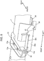
- the pedal-backward-preventive bracket 30 is fixed to the instrumental panel support member 1 via a base bracket 20.
- the pedal-backward-preventive bracket 30 is disposed below the mount bracket 11 having the pressure receiving portion 11b.
- the base bracket 20 is made by, for example, working an iron-based metal plate and fixed (welded, for example) to the instrumental panel support member 1.
- the pedal-backward-preventive bracket 30 is made by, for example, working an iron-based metal plate.
- the pedal-backward-preventive bracket 30 is placed on a bottom face of the base bracket 20 and detachably fixed to the base brackets 20 by second fasteners 31, such as bolts and nuts.
- the second fasteners 31 are handled (turned) from below.
- reference sign 20a indicates a hole provided in the base bracket 20 used for the second fastener 31.
- the pedal-backward-preventive bracket 30 extends forward from the base bracket 20, and the pedal-backward-preventive bracket 30 has a front end provided with an abut portion 30a having a substantially flat face.
- a supporting portion of the braking pedal 50 abuts the abut portion 30a when the braking pedal 50 moves backward.
- the abut portion 30a has a width (a length in the vehicle width direction) sufficiently larger than a width of the mount bracket 11 and extends to below the head-up display 10.
- the pedal-backward-preventive bracket 30 has a front end provided with a pusher 30b having a plate shape and extending in an up-and-down direction.
- the pusher 30b extends upwardly from a right end of a front extended portion 30c that slightly extends forward from a top end of the abut portion 30a.
- the pusher 30b is positioned immediately in front of the pressure receiving portion 11b of the mount bracket 11.
- the pusher 30b and the pressure receiving portion 11b constitute a load transfer portion of the present invention.
- a dashboard panel 40 is provided in front of the instrumental panel support member 1 to partition an engine room from a vehicle compartment.
- the braking pedal 50 is supported on the dashboard panel 40.
- a proximal end portion of the braking pedal 50 is swingably supported on a bracket 51 fixed to the dashboard panel 40 by a support pin 52.
- the support pin 52 is held in a support hole 51a provided in the bracket 51.
- a lower portion of the support hole 51a is partially cut out to cause the support pin 52 to come out of the support hole 51a when a force greater than or equal to a predetermined value acts on the support pin 52 from above, thereby allowing the braking pedal 50 to fall.
- a swing lever 54 is swingably supported on the bracket 51 by a pin 53. Under a normal operation, an end 54a of the swing lever 54 is positioned immediately in front of the abut portion 30a of the pedal-backward-preventive bracket 30 described above. The other end 54b of the swing lever 54 is positioned immediately above the support pin 53.
- the bracket 51 and the swing lever 54 correspond to the "supporting portion" of the present invention.
- the braking pedal 50 moves backward together with the bracket 51 and the end 54a of the swing lever 54 abuts the abut portion 30a of the pedal-backward-preventive bracket 30.
- the swing lever 54 thereby swings about the pin 53 by a reaction force given by the pedal-backward-preventive bracket 30 such that the other end 54b moves downward. Swinging of the swing lever 54 causes the support pin 52 to come out of the support hole 51a and allows the braking pedal 50 to fall downward.
- the fall of the braking pedal 50 prevents the braking pedal 50 from moving backward more than or equal to a predetermined dimension, and thus a leg of a driver is protected.
- the rearward load acts on the pedal-backward-preventive bracket 30 via the swing lever 54.
- the rearward load is received by the instrumental panel support member 1 via the pedal-backward-preventive bracket 30.
- the rearward load is input to the pressure receiving portion 11b of the mount bracket 11 through the pusher 30b of the pedal-backward-preventive bracket 30 and received by the instrumental panel support member 1 via the mount bracket 11. That is, the rearward load generated by the vehicle forward collision is efficiently distributed and transferred in two directions, namely, upward and downward directions.
- the rearward load that is input to the pedal-backward-preventive bracket 30 is also distributed to the mount bracket 11 to be transferred to the instrumental panel support member 1. This greatly improves impact resistance of the pedal-backward-preventive bracket 30. If the impact resistance is to be set to a conventional level, downsizing and weight reduction can be achieved by reducing a thickness of the pedal-backward-preventive bracket 30 since the rearward load is also distributed to the mount bracket 11. Thus, the increase in size and weight of the pedal-backward-preventive bracket 30 can be prevented or minimized and at the same time, sufficient impact resistance can be secured for the pedal-backward-preventive bracket 30.
- the head-up display 10 released from the mount bracket 11 can be handled from below and taken out through a space K (see FIG. 1 ) between the dashboard panel 40 and the instrumental panel support member 1 to a floor of the vehicle compartment.
- the procedure described above is performed in the reverse order.
- a lower panel of the instrumental panel 2 hampers mounting or dismounting of the head-up display 10
- the procedure of mounting or dismounting is performed with the lower panel removed in advance. If the steering shaft hampers the procedure, the steering shaft is removed from the instrumental panel support member 1 in advance and laid on the floor of the vehicle compartment.
- FIGS. 7 and 8 illustrate a second embodiment of the present invention.
- the component same as the first embodiment is appended with the same reference sign and description thereof is not repeated (the same can be said for a third embodiment illustrated in FIGS. 9 and 10 ).
- a front extended portion 30c of an pedal-backward-preventive bracket 30 is detachably fixed to a bottom face of a front end of a mount bracket 11.
- a fixing portion 11c is provided on the bottom face of the front end of the mount bracket 11, and the front extended portion 30c is fixed to the fixing portion 11c by a third fastener 32.
- the third fastener 32 is also handled from below.
- the fixing portion 11c, of the mount bracket 11, fixed by the third fastener 32 is provided by fixing a mounting member to the mount bracket 11 by welding, for example, the mounting member being separately prepared and having a U-shape in a front view.
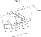
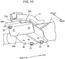
- FIGS. 9 and 10 illustrate a third embodiment of the present invention.
- a front end of an pedal-backward-preventive bracket 30 and a front end of a mount bracket 11 are detachably fixed to each other by a third fastener 32.
- a fixing portion 11d is provided on a right side face of the front end of the mount bracket 11, and a front extended portion 30c is fixed to the fixing portion 11d by the third fastener 32.
- the fixing portion 11d fixed to the mount bracket 11 by the third fastener 32 is provided by integrating an mounting member extending in the vehicle width direction and having an L-shape in a rear view with the mount bracket 11 by welding, for example.
- the fixing portion 11d is placed on a top face of the front extended portion 30c of the pedal-backward-preventive bracket 30.
- the pedal-backward-preventive bracket 30 has an upright portion 30d that extends upward by a short distance from the front end of the front extended portion 30c.
- the upright portion 30d is located immediately in front of the fixing portion 11d of the mount bracket 11.
- the present invention is not limited to the embodiments described above.
- the embodiments can suitably be modified within the scope described by the claims.
- the pedal-backward-preventive bracket 30 may directly be fixed to the instrumental panel support member 1 by a fastener without using the base bracket 20.
- a control pedal that is to be prevented from moving backward is not necessarily a braking pedal but may be an accelerator pedal or a clutch pedal. It goes without saying that an object of the present invention is not limited to the object described above but may implicitly include an object that is substantially preferable or an object described as an advantage.
- a rearward load input to the pedal-backward-preventive bracket is also distributed and transferred to the mount bracket on which the head-up display is mounted.
- a vehicle interior structure includes an instrumental panel support member to which an instrumental panel is fixed, the instrumental panel support member extending in a vehicle width direction, a pedal-backward-preventive bracket against which a supporting portion of a control panel abuts when the control pedal controlled by a foot of a driver moves backward, the pedal-backward-preventive bracket being fixed to the instrumental panel support member, a mount bracket on which a head-up display is mounted, the mount bracket being fixed to the instrumental panel support member, and a load transfer portion that is provided between the pedal-backward-preventive bracket and the mount bracket to transfer a rearward load input to the pedal-backward-preventive bracket to the mount bracket via the supporting portion.
- the rearward load input to the pedal-backward-preventive bracket is also distributed to the mount bracket and transferred to the instrumental panel support member. This greatly improves impact resistance of the pedal-backward-preventive bracket. If the impact resistance is to be set to a conventional level, downsizing and weight reduction can be achieved by reducing a thickness of the pedal-backward-preventive bracket since the rearward load is also distributed to the mount bracket. Thus, the increase in size and weight of the pedal-backward-preventive bracket can be prevented or minimized and at the same time, sufficient impact resistance can be secured for the pedal-backward-preventive bracket.
- the load transfer portion includes a pusher provided on the pedal-backward-preventive bracket, and a pressure receiving portion provided on the mount bracket and located immediately behind the pusher.
- the load transfer portion can be simplified.
- the pedal-backward-preventive bracket and the mount bracket are fixed to each other, and the load transfer portion serves as a fixing portion that fixes the pedal-backward-preventive bracket to the mount bracket.
- a rearward load can efficiently be transferred to the mount bracket via fixing which is a very strong connecting method.
- the load transfer portion is provided in a front portion, with regard to a front-and-rear direction of a vehicle, of the pedal-backward-preventive bracket.
- the load transfer portion can be provided as close as possible to a place where a rearward load is input, and thus the rearward load is efficiently transferred to the mount bracket.
- the pedal-backward-preventive bracket is longer in the vehicle width direction than the mount bracket.
- the load transfer portion can suitably be provided corresponding to the mount bracket provided at a preferable location in the vehicle width direction.
- the head-up display is detachably mounted on the mount bracket by the first fastener handled from below
- the pedal-backward-preventive bracket is detachably fixed to the instrumental panel support member by the second fastener handled from below
- a space is defined between the instrumental panel support member and a dashboard panel to allow the head-up display dismounted from the mount bracket to pass through the space while the pedal-backward-preventive bracket is removed from the instrumental panel support member.
- the head-up display can be dismounted and mounted from below through the space between the dashboard panel and the instrumental panel support member without an extensive work of dismounting the whole instrumental panel from the instrumental panel support member. This improves workability of maintaining the head-up display.
- the present invention preferably secures safety when a forward collision occurs.
Landscapes
- Engineering & Computer Science (AREA)
- Mechanical Engineering (AREA)
- Transportation (AREA)
- Chemical & Material Sciences (AREA)
- Combustion & Propulsion (AREA)
- Physics & Mathematics (AREA)
- General Physics & Mathematics (AREA)
- Automation & Control Theory (AREA)
- Instrument Panels (AREA)
- Body Structure For Vehicles (AREA)
- Mechanical Control Devices (AREA)
- Arrangement And Mounting Of Devices That Control Transmission Of Motive Force (AREA)
Abstract
Description
- The present invention relates to a vehicle interior structure.
- As described in
Patent Literature 1, a vehicle typically has a pedal-backward-preventive mechanism that prevents a control pedal (in particular, a braking pedal) controlled by a foot of a driver from moving backward further than a predetermined dimension when a forward collision occurs. - More vehicles produced nowadays have been equipped with a head-up display that presents various types of information in front of a driver as described in
Patent Literature 2. - The pedal-backward-preventive mechanism usually includes a pedal-backward-preventive bracket that is fixed to an instrumental panel support member (also referred to as a steering support member) serving as a strength member. When the control pedal moves backward in a forward collision, a supporting portion of the control pedal abuts the pedal-backward-preventive bracket and thereby the control pedal comes off, for example. In this manner, the control pedal is prevented from moving backward further than a predetermined dimension.
- The pedal-backward-preventive bracket described above needs to hold a large rearward load and thus is required to have sufficient impact resistance. To increase impact resistance, it is not preferable to simply increase a thickness or a size of the pedal-backward-preventive bracket, because the size or weight of the pedal-backward-preventive bracket is increased.
-
- Patent Literature 1:
JP 2009-237844 A - Patent Literature 2:
JP 2009-1149 A - The present invention is made in view of the problem described above. An object of the present invention is to provide a vehicle interior structure that includes a pedal-backward-preventive bracket that undergoes no or little increase in size and/or weight and has sufficient impact resistance.
- The vehicle interior structure according to the present invention includes an instrumental panel support member to which an instrumental panel is fixed, the instrumental panel support member extending in a vehicle width direction, a pedal-backward-preventive bracket against which a supporting portion of a control pedal abuts when the control pedal controlled by a foot of a driver moves backward, the pedal-backward-preventive bracket being fixed to the instrumental panel support member, a mount bracket on which a head-up display is mounted, the mount bracket being fixed to the instrumental panel support member, and a load transfer portion that is provided between the pedal-backward-preventive bracket and the mount bracket to transfer a rearward load input to the pedal-backward-preventive bracket to the mount bracket via the supporting portion.
-
-
FIG. 1 is a side sectional view of a vehicle interior structure according to a first embodiment of the present invention. -
FIG. 2 is a plan view illustrating a mounted state of a head-up display. -
FIG. 3 is a top perspective view illustrating a relationship between a mount bracket and a pedal-backward-preventive bracket. -
FIG. 4 is a bottom perspective view illustrating a relationship between the mount bracket and the pedal-backward-preventive bracket. -
FIG. 5 is a bottom view illustrating a relationship between the mount bracket and the pedal-backward-preventive bracket. -
FIG. 6 is a view of the mount bracket from which the pedal-backward-preventive bracket illustrated inFIG. 5 is removed. -
FIG. 7 is a left perspective view of a mount bracket and an pedal-backward-preventive bracket (a second embodiment). -
FIG. 8 is a right top perspective view of the mount bracket and the pedal-backward-preventive bracket (the second embodiment). -
FIG. 9 is a left top perspective view of a mount bracket and an pedal-backward-preventive bracket (a third embodiment). -
FIG. 10 is a right bottom perspective view of the mount bracket and the pedal-backward-preventive bracket (the third embodiment). - A vehicle interior structure according to a first embodiment of the present invention will be described with reference to
FIGS. 1 to 6 . In the following description, "front", "rear", "right", and "left" respectively correspond to "front", "rear", "right", and "left" of a vehicle unless specified. - In
FIG. 1 ,reference sign 1 indicates an instrumental panel support member which is a vehicle body strength member extending in a vehicle width direction. The instrumentalpanel support member 1 connects between a pair of right and left hinge pillars (not shown) and also supports a steering shaft (not shown). - An
instrumental panel 2 is fixed to the instrumentalpanel support member 1. A head-updisplay 10 is provided in theinstrumental panel 2 at an appropriate position with respect to a driver's seat. The head-up display 10 projects various types of information presented to a driver onto a region forward of a windshield through an opening 2a provided in theinstrumental panel 2.Reference sign 2b inFIG. 1 indicates an opening in which a meter panel (meter unit) such as a speed meter is installed. - As illustrated in
FIG. 2 , the head-updisplay 10 is detachably mounted byfirst fasteners 12, such as bolts, on a pair of right andleft mount brackets 11 that is fixed (is welded, for example) to the instrumentalpanel support member 1. Specifically, the head-updisplay 10 hasflanges 10a used for mounting. Theflanges 10a are placed on bottom faces of themount brackets 11 and fixed to themount brackets 11 by thefirst fasteners 12 such as bolts handled (turned) from below. InFIGS. 3 to 6 ,reference sign 11a indicates a hole provided in themount bracket 11 used for thefirst fastener 12. - The
mount bracket 11 is made by, for example, bending an iron-based metal plate. As illustrated inFIGS. 1 to 3 , themount bracket 11 is fixed to an upper portion of the instrumentalpanel support member 1 and extends in front of the instrumentalpanel support member 1. The head-updisplay 10 is mounted on themount bracket 11 to largely protrude forward from the instrumentalpanel support member 1. - One of the pair of right and left mount brackets 11 (the
mount bracket 11 in the right side inFIG. 2 ) has apressure receiving portion 11b on a side face of a front end. Thepressure receiving portion 11b is provided by integrating a receiving plate with themount bracket 11 by welding, for example, the receiving plate being made by working an iron-based metal plate. Abraking pedal 50, which will be described later, is disposed below themount bracket 11 having thepressure receiving portion 11b (inFIG. 2 , thebraking pedal 50 is hidden behind the head-up display 10). - The pedal-backward-
preventive bracket 30 is fixed to the instrumentalpanel support member 1 via abase bracket 20. The pedal-backward-preventive bracket 30 is disposed below themount bracket 11 having thepressure receiving portion 11b. Thebase bracket 20 is made by, for example, working an iron-based metal plate and fixed (welded, for example) to the instrumentalpanel support member 1. - The pedal-backward-
preventive bracket 30 is made by, for example, working an iron-based metal plate. The pedal-backward-preventive bracket 30 is placed on a bottom face of thebase bracket 20 and detachably fixed to thebase brackets 20 bysecond fasteners 31, such as bolts and nuts. Thesecond fasteners 31 are handled (turned) from below. InFIG. 6 ,reference sign 20a indicates a hole provided in thebase bracket 20 used for thesecond fastener 31. - As illustrated in
FIGS. 3 to 5 , the pedal-backward-preventive bracket 30 extends forward from thebase bracket 20, and the pedal-backward-preventive bracket 30 has a front end provided with anabut portion 30a having a substantially flat face. As will be described later, a supporting portion of thebraking pedal 50 abuts theabut portion 30a when thebraking pedal 50 moves backward. In order that the supporting portion of thebraking pedal 50 moving backward reliably abuts against theabut portion 30a even when being shifted in a right-and-left direction, theabut portion 30a has a width (a length in the vehicle width direction) sufficiently larger than a width of themount bracket 11 and extends to below the head-updisplay 10. - The pedal-backward-
preventive bracket 30 has a front end provided with apusher 30b having a plate shape and extending in an up-and-down direction. Thepusher 30b extends upwardly from a right end of a front extendedportion 30c that slightly extends forward from a top end of theabut portion 30a. - The
pusher 30b is positioned immediately in front of thepressure receiving portion 11b of themount bracket 11. When a large rearward load acts on the pedal-backward-preventive bracket 30, the rearward load is transferred to thepressure receiving portion 11b of themount bracket 11 via thepusher 30b. In this example, thepusher 30b and thepressure receiving portion 11b constitute a load transfer portion of the present invention. - In
FIG. 1 , adashboard panel 40 is provided in front of the instrumentalpanel support member 1 to partition an engine room from a vehicle compartment. Thebraking pedal 50 is supported on thedashboard panel 40. A proximal end portion of thebraking pedal 50 is swingably supported on abracket 51 fixed to thedashboard panel 40 by asupport pin 52. Thesupport pin 52 is held in asupport hole 51a provided in thebracket 51. A lower portion of thesupport hole 51a is partially cut out to cause thesupport pin 52 to come out of thesupport hole 51a when a force greater than or equal to a predetermined value acts on thesupport pin 52 from above, thereby allowing thebraking pedal 50 to fall. - A
swing lever 54 is swingably supported on thebracket 51 by apin 53. Under a normal operation, anend 54a of theswing lever 54 is positioned immediately in front of theabut portion 30a of the pedal-backward-preventive bracket 30 described above. Theother end 54b of theswing lever 54 is positioned immediately above thesupport pin 53. In this example, thebracket 51 and theswing lever 54 correspond to the "supporting portion" of the present invention. - In the configuration described above, when a forward collision occurs, the
braking pedal 50 moves backward together with thebracket 51 and theend 54a of theswing lever 54 abuts theabut portion 30a of the pedal-backward-preventive bracket 30. Theswing lever 54 thereby swings about thepin 53 by a reaction force given by the pedal-backward-preventive bracket 30 such that theother end 54b moves downward. Swinging of theswing lever 54 causes thesupport pin 52 to come out of thesupport hole 51a and allows thebraking pedal 50 to fall downward. The fall of thebraking pedal 50 prevents thebraking pedal 50 from moving backward more than or equal to a predetermined dimension, and thus a leg of a driver is protected. - Meanwhile, the rearward load acts on the pedal-backward-
preventive bracket 30 via theswing lever 54. The rearward load is received by the instrumentalpanel support member 1 via the pedal-backward-preventive bracket 30. The rearward load is input to thepressure receiving portion 11b of themount bracket 11 through thepusher 30b of the pedal-backward-preventive bracket 30 and received by the instrumentalpanel support member 1 via themount bracket 11. That is, the rearward load generated by the vehicle forward collision is efficiently distributed and transferred in two directions, namely, upward and downward directions. - As described above, the rearward load that is input to the pedal-backward-
preventive bracket 30 is also distributed to themount bracket 11 to be transferred to the instrumentalpanel support member 1. This greatly improves impact resistance of the pedal-backward-preventive bracket 30. If the impact resistance is to be set to a conventional level, downsizing and weight reduction can be achieved by reducing a thickness of the pedal-backward-preventive bracket 30 since the rearward load is also distributed to themount bracket 11. Thus, the increase in size and weight of the pedal-backward-preventive bracket 30 can be prevented or minimized and at the same time, sufficient impact resistance can be secured for the pedal-backward-preventive bracket 30. - Now, removing of the head-up
display 10 from inside theinstrumental panel 2 for checking or replacing the head-updisplay 10 will be described. First, by handling thesecond fastener 31 from below, the pedal-backward-preventive bracket 30 is removed from thebase bracket 20. Then, thefirst fastener 12 is handled from below to release the fixation of the head-updisplay 10 with respect to themount bracket 11. - The head-up
display 10 released from themount bracket 11 can be handled from below and taken out through a space K (seeFIG. 1 ) between thedashboard panel 40 and the instrumentalpanel support member 1 to a floor of the vehicle compartment. - To reassemble the head-up
display 10 in the vehicle, the procedure described above is performed in the reverse order. When a lower panel of theinstrumental panel 2 hampers mounting or dismounting of the head-updisplay 10, the procedure of mounting or dismounting is performed with the lower panel removed in advance. If the steering shaft hampers the procedure, the steering shaft is removed from the instrumentalpanel support member 1 in advance and laid on the floor of the vehicle compartment. -
FIGS. 7 and8 illustrate a second embodiment of the present invention. The component same as the first embodiment is appended with the same reference sign and description thereof is not repeated (the same can be said for a third embodiment illustrated inFIGS. 9 and10 ). - In the second embodiment, a front
extended portion 30c of an pedal-backward-preventive bracket 30 is detachably fixed to a bottom face of a front end of amount bracket 11. In more detail, a fixingportion 11c is provided on the bottom face of the front end of themount bracket 11, and the frontextended portion 30c is fixed to the fixingportion 11c by athird fastener 32. Thethird fastener 32 is also handled from below. The fixingportion 11c, of themount bracket 11, fixed by thethird fastener 32 is provided by fixing a mounting member to themount bracket 11 by welding, for example, the mounting member being separately prepared and having a U-shape in a front view. -
FIGS. 9 and10 illustrate a third embodiment of the present invention. In the present embodiment, a front end of an pedal-backward-preventive bracket 30 and a front end of amount bracket 11 are detachably fixed to each other by athird fastener 32. In more detail, a fixingportion 11d is provided on a right side face of the front end of themount bracket 11, and a frontextended portion 30c is fixed to the fixingportion 11d by thethird fastener 32. In the present embodiment, the fixingportion 11d fixed to themount bracket 11 by thethird fastener 32 is provided by integrating an mounting member extending in the vehicle width direction and having an L-shape in a rear view with themount bracket 11 by welding, for example. The fixingportion 11d is placed on a top face of the frontextended portion 30c of the pedal-backward-preventive bracket 30. - Furthermore in the third embodiment, the pedal-backward-
preventive bracket 30 has anupright portion 30d that extends upward by a short distance from the front end of the frontextended portion 30c. Theupright portion 30d is located immediately in front of the fixingportion 11d of themount bracket 11. With such a configuration, a load is not only transferred through thethird fastener 32 to the fixingportion 11d but also through theupright portion 30d to the fixingportion 11d, and thereby a load is further efficiently transferred from the pedal-backward-preventive bracket 30 to themount bracket 11. - The present invention is not limited to the embodiments described above. The embodiments can suitably be modified within the scope described by the claims. The pedal-backward-
preventive bracket 30 may directly be fixed to the instrumentalpanel support member 1 by a fastener without using thebase bracket 20. A control pedal that is to be prevented from moving backward is not necessarily a braking pedal but may be an accelerator pedal or a clutch pedal. It goes without saying that an object of the present invention is not limited to the object described above but may implicitly include an object that is substantially preferable or an object described as an advantage. - The present invention described above is summarized as below.
- In the present invention, a rearward load input to the pedal-backward-preventive bracket is also distributed and transferred to the mount bracket on which the head-up display is mounted. That is, a vehicle interior structure according to the present invention includes an instrumental panel support member to which an instrumental panel is fixed, the instrumental panel support member extending in a vehicle width direction, a pedal-backward-preventive bracket against which a supporting portion of a control panel abuts when the control pedal controlled by a foot of a driver moves backward, the pedal-backward-preventive bracket being fixed to the instrumental panel support member, a mount bracket on which a head-up display is mounted, the mount bracket being fixed to the instrumental panel support member, and a load transfer portion that is provided between the pedal-backward-preventive bracket and the mount bracket to transfer a rearward load input to the pedal-backward-preventive bracket to the mount bracket via the supporting portion.
- According to the structure described above, when a forward collision occurs, the rearward load input to the pedal-backward-preventive bracket is also distributed to the mount bracket and transferred to the instrumental panel support member. This greatly improves impact resistance of the pedal-backward-preventive bracket. If the impact resistance is to be set to a conventional level, downsizing and weight reduction can be achieved by reducing a thickness of the pedal-backward-preventive bracket since the rearward load is also distributed to the mount bracket. Thus, the increase in size and weight of the pedal-backward-preventive bracket can be prevented or minimized and at the same time, sufficient impact resistance can be secured for the pedal-backward-preventive bracket.
- In the structure described above, the load transfer portion includes a pusher provided on the pedal-backward-preventive bracket, and a pressure receiving portion provided on the mount bracket and located immediately behind the pusher.
- According to this structure, preferably, the load transfer portion can be simplified.
- The pedal-backward-preventive bracket and the mount bracket are fixed to each other, and the load transfer portion serves as a fixing portion that fixes the pedal-backward-preventive bracket to the mount bracket.
- According to this structure, a rearward load can efficiently be transferred to the mount bracket via fixing which is a very strong connecting method.
- The load transfer portion is provided in a front portion, with regard to a front-and-rear direction of a vehicle, of the pedal-backward-preventive bracket.
- According to this structure, preferably, the load transfer portion can be provided as close as possible to a place where a rearward load is input, and thus the rearward load is efficiently transferred to the mount bracket.
- The pedal-backward-preventive bracket is longer in the vehicle width direction than the mount bracket.
- According to this structure, backward movement of the control pedal is prevented even when the control pedal is shifted in the vehicle width direction. According to this structure, preferably, the load transfer portion can suitably be provided corresponding to the mount bracket provided at a preferable location in the vehicle width direction.
- Furthermore, the head-up display is detachably mounted on the mount bracket by the first fastener handled from below, the pedal-backward-preventive bracket is detachably fixed to the instrumental panel support member by the second fastener handled from below, and a space is defined between the instrumental panel support member and a dashboard panel to allow the head-up display dismounted from the mount bracket to pass through the space while the pedal-backward-preventive bracket is removed from the instrumental panel support member.
- According to this configuration, the head-up display can be dismounted and mounted from below through the space between the dashboard panel and the instrumental panel support member without an extensive work of dismounting the whole instrumental panel from the instrumental panel support member. This improves workability of maintaining the head-up display.
- The present invention preferably secures safety when a forward collision occurs.
Claims (6)
- A vehicle interior structure comprising:an instrumental panel support member to which an instrumental panel is fixed, the instrumental panel support member extending in a vehicle width direction;a pedal-backward-preventive bracket against which a supporting portion of a control pedal abuts when the control pedal controlled by a foot of a driver moves backward, the pedal-backward-preventive bracket being fixed to the instrumental panel support member;a mount bracket on which a head-up display is mounted, the mount bracket being fixed to the instrumental panel support member; anda load transfer portion that is provided between the pedal-backward-preventive bracket and the mount bracket to transfer a rearward load input to the pedal-backward-preventive bracket to the mount bracket via the supporting portion.
- The vehicle interior structure according to claim 1, wherein
the load transfer portion includes a pusher provided on the pedal-backward-preventive bracket, and a pressure receiving portion provided on the mount bracket and located immediately behind the pusher. - The vehicle interior structure according to claim 1, wherein
the pedal-backward-preventive bracket and the mount bracket are fixed to each other, and
the load transfer portion is a fixing portion that fixes the pedal-backward-preventive bracket to the mount bracket. - The vehicle interior structure according to any one of claims 1 to 3, wherein
the load transfer portion is provided in a front portion, with regard to a front-and-rear direction of a vehicle, of the pedal-backward-preventive bracket. - The vehicle interior structure according to any one of claims 1 to 4, wherein
the pedal-backward-preventive bracket is longer in the vehicle width direction than the mount bracket. - The vehicle interior structure according to any one of claims 1 to 5, wherein
the head-up display is detachably mounted on the mount bracket by a first fastener handled from below,
the pedal-backward-preventive bracket is detachably fixed to the instrumental panel support member by a second fastener handled from below, and
a space is defined between the instrumental panel support member and a dashboard panel to allow the head-up display dismounted from the mount bracket to pass through the space in a state where the pedal-backward-preventive bracket is removed from the instrumental panel support member.
Applications Claiming Priority (2)
| Application Number | Priority Date | Filing Date | Title |
|---|---|---|---|
| JP2017027675A JP6439811B2 (en) | 2017-02-17 | 2017-02-17 | Vehicle interior structure |
| PCT/JP2018/004211 WO2018150976A1 (en) | 2017-02-17 | 2018-02-07 | Structure for vehicle interior |
Publications (3)
| Publication Number | Publication Date |
|---|---|
| EP3418164A1 true EP3418164A1 (en) | 2018-12-26 |
| EP3418164A4 EP3418164A4 (en) | 2019-04-10 |
| EP3418164B1 EP3418164B1 (en) | 2020-04-08 |
Family
ID=63170254
Family Applications (1)
| Application Number | Title | Priority Date | Filing Date |
|---|---|---|---|
| EP18754014.1A Active EP3418164B1 (en) | 2017-02-17 | 2018-02-07 | Structure for vehicle interior |
Country Status (5)
| Country | Link |
|---|---|
| US (1) | US10338627B2 (en) |
| EP (1) | EP3418164B1 (en) |
| JP (1) | JP6439811B2 (en) |
| CN (1) | CN110312656B (en) |
| WO (1) | WO2018150976A1 (en) |
Families Citing this family (1)
| Publication number | Priority date | Publication date | Assignee | Title |
|---|---|---|---|---|
| JP6712460B2 (en) * | 2015-11-26 | 2020-06-24 | ダイキョーニシカワ株式会社 | Vehicle interior structure |
Family Cites Families (18)
| Publication number | Priority date | Publication date | Assignee | Title |
|---|---|---|---|---|
| KR100552747B1 (en) * | 2003-11-13 | 2006-02-20 | 현대자동차주식회사 | brake pedal mounting structure for preventing ankle wound of vehicles |
| JP4502660B2 (en) * | 2004-02-20 | 2010-07-14 | 本田技研工業株式会社 | Automobile operation pedal device |
| US7896396B2 (en) * | 2004-06-29 | 2011-03-01 | Faurecia Innenraum Systeme Gmbh | Automotive vehicle and also support arrangement |
| JP4234095B2 (en) * | 2004-12-09 | 2009-03-04 | 株式会社エフテック | Automobile operation pedal device |
| JP4979986B2 (en) * | 2006-05-31 | 2012-07-18 | 日産自動車株式会社 | Automotive brake pedal equipment |
| JP2009003636A (en) * | 2007-06-20 | 2009-01-08 | Mazda Motor Corp | Retreat prevention structure for operation pedal |
| JP2009001149A (en) | 2007-06-21 | 2009-01-08 | Calsonic Kansei Corp | Head-up display mounting part structure |
| JP2009237844A (en) * | 2008-03-27 | 2009-10-15 | Mazda Motor Corp | Support structure of vehicle operating pedal |
| JP5937502B2 (en) * | 2012-12-14 | 2016-06-22 | 豊田鉄工株式会社 | Pedal device for vehicle |
| JP6015601B2 (en) | 2013-09-06 | 2016-10-26 | トヨタ自動車株式会社 | Instrument panel reinforcement structure |
| JP6136845B2 (en) * | 2013-10-21 | 2017-05-31 | トヨタ自動車株式会社 | Vehicle front structure |
| KR101987501B1 (en) * | 2013-12-13 | 2019-09-30 | 현대자동차주식회사 | Common Reverse prevented Driver's Injury type Pedal |
| EP3124340B1 (en) * | 2014-03-26 | 2018-11-28 | Yorozu Corporation | Brake pedal device for automotive vehicle |
| JP6361484B2 (en) * | 2014-11-28 | 2018-07-25 | トヨタ自動車株式会社 | Driver protection device |
| US9821777B2 (en) * | 2015-02-20 | 2017-11-21 | Toyota Jidosha Kabushiki Kaisha | Vehicle brake pedal device |
| WO2016208064A1 (en) * | 2015-06-26 | 2016-12-29 | 本田技研工業株式会社 | Vehicle body front part structure |
| JP6437127B2 (en) * | 2015-09-25 | 2018-12-12 | カルソニックカンセイ株式会社 | Car body mounting structure for vehicle head-up display device |
| CN205819169U (en) * | 2016-07-26 | 2016-12-21 | 长城汽车股份有限公司 | Pedal of vehicles anti-intrusion structure |
-
2017
- 2017-02-17 JP JP2017027675A patent/JP6439811B2/en active Active
-
2018
- 2018-02-07 WO PCT/JP2018/004211 patent/WO2018150976A1/en active Application Filing
- 2018-02-07 CN CN201880001414.2A patent/CN110312656B/en not_active Expired - Fee Related
- 2018-02-07 EP EP18754014.1A patent/EP3418164B1/en active Active
- 2018-02-07 US US16/086,986 patent/US10338627B2/en active Active
Also Published As
| Publication number | Publication date |
|---|---|
| CN110312656B (en) | 2021-07-23 |
| WO2018150976A1 (en) | 2018-08-23 |
| JP2018131137A (en) | 2018-08-23 |
| JP6439811B2 (en) | 2018-12-19 |
| CN110312656A (en) | 2019-10-08 |
| US10338627B2 (en) | 2019-07-02 |
| US20190050017A1 (en) | 2019-02-14 |
| EP3418164B1 (en) | 2020-04-08 |
| EP3418164A4 (en) | 2019-04-10 |
Similar Documents
| Publication | Publication Date | Title |
|---|---|---|
| EP1767420B1 (en) | Anti-intrusion pedal system | |
| JP4029800B2 (en) | Automobile pedal support structure | |
| EP3418164B1 (en) | Structure for vehicle interior | |
| JP2003015756A (en) | Structure for suppressing displacement of vehicle pedal | |
| US7849950B2 (en) | Brake apparatus for vehicle | |
| WO2007063657A1 (en) | Pedal structure | |
| JP2004348371A (en) | Pedal support structure for automobile | |
| JP6716524B2 (en) | Vehicle operation pedal device | |
| US6419270B1 (en) | Integrated steering column and pedal mounting system | |
| EP3822736B1 (en) | Operation pedal device for vehicle | |
| CN110325404B (en) | Mounting structure of vehicle accessory device | |
| WO2016121154A1 (en) | Vehicle pedal device-use backward movement prevention device | |
| JP5038767B2 (en) | Steering column mounting structure | |
| JP6575552B2 (en) | Vehicle interior structure | |
| JP2006178611A (en) | Vehicle pedal support structure | |
| JP2003341488A (en) | Pedal retreat amount suppressing device | |
| EP3599530B1 (en) | Cabin front wall structure of vehicle | |
| JP6352229B2 (en) | Retreat prevention device for vehicle pedal device | |
| JP2000108709A (en) | Supporting structure for vehicle shift operation device | |
| JPH07165088A (en) | Steering supporting device for vehicle and assembling method thereof | |
| JP2017211899A (en) | Retreat prevention device for vehicle pedal device | |
| JP2017109697A (en) | Front structure for vehicle body | |
| JP2005035378A (en) | Vehicle interior equipment supporting structure |
Legal Events
| Date | Code | Title | Description |
|---|---|---|---|
| STAA | Information on the status of an ep patent application or granted ep patent |
Free format text: STATUS: THE INTERNATIONAL PUBLICATION HAS BEEN MADE |
|
| PUAI | Public reference made under article 153(3) epc to a published international application that has entered the european phase |
Free format text: ORIGINAL CODE: 0009012 |
|
| STAA | Information on the status of an ep patent application or granted ep patent |
Free format text: STATUS: REQUEST FOR EXAMINATION WAS MADE |
|
| 17P | Request for examination filed |
Effective date: 20180921 |
|
| AK | Designated contracting states |
Kind code of ref document: A1 Designated state(s): AL AT BE BG CH CY CZ DE DK EE ES FI FR GB GR HR HU IE IS IT LI LT LU LV MC MK MT NL NO PL PT RO RS SE SI SK SM TR |
|
| AX | Request for extension of the european patent |
Extension state: BA ME |
|
| RIC1 | Information provided on ipc code assigned before grant |
Ipc: B60K 37/00 20060101ALI20180824BHEP Ipc: B60K 23/02 20060101ALI20180824BHEP Ipc: G05G 1/32 20080401ALI20180824BHEP Ipc: B62D 25/08 20060101AFI20180824BHEP |
|
| A4 | Supplementary search report drawn up and despatched |
Effective date: 20190314 |
|
| RIC1 | Information provided on ipc code assigned before grant |
Ipc: B60K 37/00 20060101ALI20190307BHEP Ipc: B62D 25/08 20060101AFI20190307BHEP Ipc: G05G 1/32 20080401ALI20190307BHEP Ipc: B60K 23/02 20060101ALI20190307BHEP |
|
| GRAP | Despatch of communication of intention to grant a patent |
Free format text: ORIGINAL CODE: EPIDOSNIGR1 |
|
| STAA | Information on the status of an ep patent application or granted ep patent |
Free format text: STATUS: GRANT OF PATENT IS INTENDED |
|
| DAV | Request for validation of the european patent (deleted) | ||
| DAX | Request for extension of the european patent (deleted) | ||
| INTG | Intention to grant announced |
Effective date: 20191028 |
|
| GRAS | Grant fee paid |
Free format text: ORIGINAL CODE: EPIDOSNIGR3 |
|
| GRAA | (expected) grant |
Free format text: ORIGINAL CODE: 0009210 |
|
| STAA | Information on the status of an ep patent application or granted ep patent |
Free format text: STATUS: THE PATENT HAS BEEN GRANTED |
|
| AK | Designated contracting states |
Kind code of ref document: B1 Designated state(s): AL AT BE BG CH CY CZ DE DK EE ES FI FR GB GR HR HU IE IS IT LI LT LU LV MC MK MT NL NO PL PT RO RS SE SI SK SM TR |
|
| REG | Reference to a national code |
Ref country code: AT Ref legal event code: REF Ref document number: 1254021 Country of ref document: AT Kind code of ref document: T Effective date: 20200415 Ref country code: CH Ref legal event code: EP |
|
| REG | Reference to a national code |
Ref country code: DE Ref legal event code: R096 Ref document number: 602018003660 Country of ref document: DE |
|
| REG | Reference to a national code |
Ref country code: IE Ref legal event code: FG4D |
|
| REG | Reference to a national code |
Ref country code: NL Ref legal event code: MP Effective date: 20200408 |
|
| REG | Reference to a national code |
Ref country code: LT Ref legal event code: MG4D |
|
| PG25 | Lapsed in a contracting state [announced via postgrant information from national office to epo] |
Ref country code: NL Free format text: LAPSE BECAUSE OF FAILURE TO SUBMIT A TRANSLATION OF THE DESCRIPTION OR TO PAY THE FEE WITHIN THE PRESCRIBED TIME-LIMIT Effective date: 20200408 Ref country code: PT Free format text: LAPSE BECAUSE OF FAILURE TO SUBMIT A TRANSLATION OF THE DESCRIPTION OR TO PAY THE FEE WITHIN THE PRESCRIBED TIME-LIMIT Effective date: 20200817 Ref country code: FI Free format text: LAPSE BECAUSE OF FAILURE TO SUBMIT A TRANSLATION OF THE DESCRIPTION OR TO PAY THE FEE WITHIN THE PRESCRIBED TIME-LIMIT Effective date: 20200408 Ref country code: IS Free format text: LAPSE BECAUSE OF FAILURE TO SUBMIT A TRANSLATION OF THE DESCRIPTION OR TO PAY THE FEE WITHIN THE PRESCRIBED TIME-LIMIT Effective date: 20200808 Ref country code: SE Free format text: LAPSE BECAUSE OF FAILURE TO SUBMIT A TRANSLATION OF THE DESCRIPTION OR TO PAY THE FEE WITHIN THE PRESCRIBED TIME-LIMIT Effective date: 20200408 Ref country code: NO Free format text: LAPSE BECAUSE OF FAILURE TO SUBMIT A TRANSLATION OF THE DESCRIPTION OR TO PAY THE FEE WITHIN THE PRESCRIBED TIME-LIMIT Effective date: 20200708 Ref country code: GR Free format text: LAPSE BECAUSE OF FAILURE TO SUBMIT A TRANSLATION OF THE DESCRIPTION OR TO PAY THE FEE WITHIN THE PRESCRIBED TIME-LIMIT Effective date: 20200709 Ref country code: LT Free format text: LAPSE BECAUSE OF FAILURE TO SUBMIT A TRANSLATION OF THE DESCRIPTION OR TO PAY THE FEE WITHIN THE PRESCRIBED TIME-LIMIT Effective date: 20200408 |
|
| REG | Reference to a national code |
Ref country code: AT Ref legal event code: MK05 Ref document number: 1254021 Country of ref document: AT Kind code of ref document: T Effective date: 20200408 |
|
| PG25 | Lapsed in a contracting state [announced via postgrant information from national office to epo] |
Ref country code: BG Free format text: LAPSE BECAUSE OF FAILURE TO SUBMIT A TRANSLATION OF THE DESCRIPTION OR TO PAY THE FEE WITHIN THE PRESCRIBED TIME-LIMIT Effective date: 20200708 Ref country code: HR Free format text: LAPSE BECAUSE OF FAILURE TO SUBMIT A TRANSLATION OF THE DESCRIPTION OR TO PAY THE FEE WITHIN THE PRESCRIBED TIME-LIMIT Effective date: 20200408 Ref country code: LV Free format text: LAPSE BECAUSE OF FAILURE TO SUBMIT A TRANSLATION OF THE DESCRIPTION OR TO PAY THE FEE WITHIN THE PRESCRIBED TIME-LIMIT Effective date: 20200408 Ref country code: RS Free format text: LAPSE BECAUSE OF FAILURE TO SUBMIT A TRANSLATION OF THE DESCRIPTION OR TO PAY THE FEE WITHIN THE PRESCRIBED TIME-LIMIT Effective date: 20200408 |
|
| PG25 | Lapsed in a contracting state [announced via postgrant information from national office to epo] |
Ref country code: AL Free format text: LAPSE BECAUSE OF FAILURE TO SUBMIT A TRANSLATION OF THE DESCRIPTION OR TO PAY THE FEE WITHIN THE PRESCRIBED TIME-LIMIT Effective date: 20200408 |
|
| REG | Reference to a national code |
Ref country code: DE Ref legal event code: R097 Ref document number: 602018003660 Country of ref document: DE |
|
| PG25 | Lapsed in a contracting state [announced via postgrant information from national office to epo] |
Ref country code: ES Free format text: LAPSE BECAUSE OF FAILURE TO SUBMIT A TRANSLATION OF THE DESCRIPTION OR TO PAY THE FEE WITHIN THE PRESCRIBED TIME-LIMIT Effective date: 20200408 Ref country code: RO Free format text: LAPSE BECAUSE OF FAILURE TO SUBMIT A TRANSLATION OF THE DESCRIPTION OR TO PAY THE FEE WITHIN THE PRESCRIBED TIME-LIMIT Effective date: 20200408 Ref country code: AT Free format text: LAPSE BECAUSE OF FAILURE TO SUBMIT A TRANSLATION OF THE DESCRIPTION OR TO PAY THE FEE WITHIN THE PRESCRIBED TIME-LIMIT Effective date: 20200408 Ref country code: SM Free format text: LAPSE BECAUSE OF FAILURE TO SUBMIT A TRANSLATION OF THE DESCRIPTION OR TO PAY THE FEE WITHIN THE PRESCRIBED TIME-LIMIT Effective date: 20200408 Ref country code: EE Free format text: LAPSE BECAUSE OF FAILURE TO SUBMIT A TRANSLATION OF THE DESCRIPTION OR TO PAY THE FEE WITHIN THE PRESCRIBED TIME-LIMIT Effective date: 20200408 Ref country code: DK Free format text: LAPSE BECAUSE OF FAILURE TO SUBMIT A TRANSLATION OF THE DESCRIPTION OR TO PAY THE FEE WITHIN THE PRESCRIBED TIME-LIMIT Effective date: 20200408 Ref country code: IT Free format text: LAPSE BECAUSE OF FAILURE TO SUBMIT A TRANSLATION OF THE DESCRIPTION OR TO PAY THE FEE WITHIN THE PRESCRIBED TIME-LIMIT Effective date: 20200408 Ref country code: CZ Free format text: LAPSE BECAUSE OF FAILURE TO SUBMIT A TRANSLATION OF THE DESCRIPTION OR TO PAY THE FEE WITHIN THE PRESCRIBED TIME-LIMIT Effective date: 20200408 |
|
| PLBE | No opposition filed within time limit |
Free format text: ORIGINAL CODE: 0009261 |
|
| STAA | Information on the status of an ep patent application or granted ep patent |
Free format text: STATUS: NO OPPOSITION FILED WITHIN TIME LIMIT |
|
| PG25 | Lapsed in a contracting state [announced via postgrant information from national office to epo] |
Ref country code: PL Free format text: LAPSE BECAUSE OF FAILURE TO SUBMIT A TRANSLATION OF THE DESCRIPTION OR TO PAY THE FEE WITHIN THE PRESCRIBED TIME-LIMIT Effective date: 20200408 Ref country code: SK Free format text: LAPSE BECAUSE OF FAILURE TO SUBMIT A TRANSLATION OF THE DESCRIPTION OR TO PAY THE FEE WITHIN THE PRESCRIBED TIME-LIMIT Effective date: 20200408 |
|
| 26N | No opposition filed |
Effective date: 20210112 |
|
| PG25 | Lapsed in a contracting state [announced via postgrant information from national office to epo] |
Ref country code: SI Free format text: LAPSE BECAUSE OF FAILURE TO SUBMIT A TRANSLATION OF THE DESCRIPTION OR TO PAY THE FEE WITHIN THE PRESCRIBED TIME-LIMIT Effective date: 20200408 |
|
| PGFP | Annual fee paid to national office [announced via postgrant information from national office to epo] |
Ref country code: DE Payment date: 20210126 Year of fee payment: 4 |
|
| PG25 | Lapsed in a contracting state [announced via postgrant information from national office to epo] |
Ref country code: MC Free format text: LAPSE BECAUSE OF FAILURE TO SUBMIT A TRANSLATION OF THE DESCRIPTION OR TO PAY THE FEE WITHIN THE PRESCRIBED TIME-LIMIT Effective date: 20200408 |
|
| REG | Reference to a national code |
Ref country code: BE Ref legal event code: MM Effective date: 20210228 |
|
| PG25 | Lapsed in a contracting state [announced via postgrant information from national office to epo] |
Ref country code: LI Free format text: LAPSE BECAUSE OF NON-PAYMENT OF DUE FEES Effective date: 20210228 Ref country code: LU Free format text: LAPSE BECAUSE OF NON-PAYMENT OF DUE FEES Effective date: 20210207 Ref country code: CH Free format text: LAPSE BECAUSE OF NON-PAYMENT OF DUE FEES Effective date: 20210228 |
|
| PG25 | Lapsed in a contracting state [announced via postgrant information from national office to epo] |
Ref country code: FR Free format text: LAPSE BECAUSE OF NON-PAYMENT OF DUE FEES Effective date: 20210228 Ref country code: IE Free format text: LAPSE BECAUSE OF NON-PAYMENT OF DUE FEES Effective date: 20210207 |
|
| PG25 | Lapsed in a contracting state [announced via postgrant information from national office to epo] |
Ref country code: BE Free format text: LAPSE BECAUSE OF NON-PAYMENT OF DUE FEES Effective date: 20210228 |
|
| REG | Reference to a national code |
Ref country code: DE Ref legal event code: R119 Ref document number: 602018003660 Country of ref document: DE |
|
| GBPC | Gb: european patent ceased through non-payment of renewal fee |
Effective date: 20220207 |
|
| PG25 | Lapsed in a contracting state [announced via postgrant information from national office to epo] |
Ref country code: GB Free format text: LAPSE BECAUSE OF NON-PAYMENT OF DUE FEES Effective date: 20220207 Ref country code: DE Free format text: LAPSE BECAUSE OF NON-PAYMENT OF DUE FEES Effective date: 20220901 |
|
| PG25 | Lapsed in a contracting state [announced via postgrant information from national office to epo] |
Ref country code: CY Free format text: LAPSE BECAUSE OF FAILURE TO SUBMIT A TRANSLATION OF THE DESCRIPTION OR TO PAY THE FEE WITHIN THE PRESCRIBED TIME-LIMIT Effective date: 20200408 |
|
| PG25 | Lapsed in a contracting state [announced via postgrant information from national office to epo] |
Ref country code: HU Free format text: LAPSE BECAUSE OF FAILURE TO SUBMIT A TRANSLATION OF THE DESCRIPTION OR TO PAY THE FEE WITHIN THE PRESCRIBED TIME-LIMIT; INVALID AB INITIO Effective date: 20180207 |
|
| PG25 | Lapsed in a contracting state [announced via postgrant information from national office to epo] |
Ref country code: MK Free format text: LAPSE BECAUSE OF FAILURE TO SUBMIT A TRANSLATION OF THE DESCRIPTION OR TO PAY THE FEE WITHIN THE PRESCRIBED TIME-LIMIT Effective date: 20200408 |