EP2907684A1 - Fuel inlet - Google Patents
Fuel inlet Download PDFInfo
- Publication number
- EP2907684A1 EP2907684A1 EP13845907.8A EP13845907A EP2907684A1 EP 2907684 A1 EP2907684 A1 EP 2907684A1 EP 13845907 A EP13845907 A EP 13845907A EP 2907684 A1 EP2907684 A1 EP 2907684A1
- Authority
- EP
- European Patent Office
- Prior art keywords
- component
- fuel
- inlet pipe
- end portion
- air vent
- Prior art date
- Legal status (The legal status is an assumption and is not a legal conclusion. Google has not performed a legal analysis and makes no representation as to the accuracy of the status listed.)
- Withdrawn
Links
- 239000000446 fuel Substances 0.000 title claims abstract description 104
- 239000000945 filler Substances 0.000 claims abstract description 34
- 239000002828 fuel tank Substances 0.000 claims abstract description 23
- 230000007246 mechanism Effects 0.000 claims abstract description 19
- 239000000463 material Substances 0.000 claims description 32
- 238000004519 manufacturing process Methods 0.000 description 20
- 238000011144 upstream manufacturing Methods 0.000 description 14
- 238000000034 method Methods 0.000 description 8
- 230000008569 process Effects 0.000 description 8
- 230000008859 change Effects 0.000 description 7
- 230000009191 jumping Effects 0.000 description 7
- 238000004080 punching Methods 0.000 description 7
- 230000000052 comparative effect Effects 0.000 description 6
- 238000003466 welding Methods 0.000 description 6
- 229910001220 stainless steel Inorganic materials 0.000 description 5
- 239000010935 stainless steel Substances 0.000 description 5
- 230000000694 effects Effects 0.000 description 4
- 238000007664 blowing Methods 0.000 description 3
- 239000002184 metal Substances 0.000 description 3
- 238000000137 annealing Methods 0.000 description 2
- 238000013459 approach Methods 0.000 description 2
- 238000005219 brazing Methods 0.000 description 2
- 239000003502 gasoline Substances 0.000 description 2
- 230000008901 benefit Effects 0.000 description 1
- 230000009467 reduction Effects 0.000 description 1
Images


Classifications
-
- B—PERFORMING OPERATIONS; TRANSPORTING
- B60—VEHICLES IN GENERAL
- B60K—ARRANGEMENT OR MOUNTING OF PROPULSION UNITS OR OF TRANSMISSIONS IN VEHICLES; ARRANGEMENT OR MOUNTING OF PLURAL DIVERSE PRIME-MOVERS IN VEHICLES; AUXILIARY DRIVES FOR VEHICLES; INSTRUMENTATION OR DASHBOARDS FOR VEHICLES; ARRANGEMENTS IN CONNECTION WITH COOLING, AIR INTAKE, GAS EXHAUST OR FUEL SUPPLY OF PROPULSION UNITS IN VEHICLES
- B60K15/00—Arrangement in connection with fuel supply of combustion engines or other fuel consuming energy converters, e.g. fuel cells; Mounting or construction of fuel tanks
- B60K15/03—Fuel tanks
- B60K15/04—Tank inlets
-
- B—PERFORMING OPERATIONS; TRANSPORTING
- B60—VEHICLES IN GENERAL
- B60K—ARRANGEMENT OR MOUNTING OF PROPULSION UNITS OR OF TRANSMISSIONS IN VEHICLES; ARRANGEMENT OR MOUNTING OF PLURAL DIVERSE PRIME-MOVERS IN VEHICLES; AUXILIARY DRIVES FOR VEHICLES; INSTRUMENTATION OR DASHBOARDS FOR VEHICLES; ARRANGEMENTS IN CONNECTION WITH COOLING, AIR INTAKE, GAS EXHAUST OR FUEL SUPPLY OF PROPULSION UNITS IN VEHICLES
- B60K15/00—Arrangement in connection with fuel supply of combustion engines or other fuel consuming energy converters, e.g. fuel cells; Mounting or construction of fuel tanks
- B60K15/03—Fuel tanks
- B60K15/035—Fuel tanks characterised by venting means
-
- B—PERFORMING OPERATIONS; TRANSPORTING
- B60—VEHICLES IN GENERAL
- B60K—ARRANGEMENT OR MOUNTING OF PROPULSION UNITS OR OF TRANSMISSIONS IN VEHICLES; ARRANGEMENT OR MOUNTING OF PLURAL DIVERSE PRIME-MOVERS IN VEHICLES; AUXILIARY DRIVES FOR VEHICLES; INSTRUMENTATION OR DASHBOARDS FOR VEHICLES; ARRANGEMENTS IN CONNECTION WITH COOLING, AIR INTAKE, GAS EXHAUST OR FUEL SUPPLY OF PROPULSION UNITS IN VEHICLES
- B60K15/00—Arrangement in connection with fuel supply of combustion engines or other fuel consuming energy converters, e.g. fuel cells; Mounting or construction of fuel tanks
- B60K15/03—Fuel tanks
- B60K2015/03328—Arrangements or special measures related to fuel tanks or fuel handling
- B60K2015/03453—Arrangements or special measures related to fuel tanks or fuel handling for fixing or mounting parts of the fuel tank together
- B60K2015/0346—Arrangements or special measures related to fuel tanks or fuel handling for fixing or mounting parts of the fuel tank together by welding
-
- B—PERFORMING OPERATIONS; TRANSPORTING
- B60—VEHICLES IN GENERAL
- B60K—ARRANGEMENT OR MOUNTING OF PROPULSION UNITS OR OF TRANSMISSIONS IN VEHICLES; ARRANGEMENT OR MOUNTING OF PLURAL DIVERSE PRIME-MOVERS IN VEHICLES; AUXILIARY DRIVES FOR VEHICLES; INSTRUMENTATION OR DASHBOARDS FOR VEHICLES; ARRANGEMENTS IN CONNECTION WITH COOLING, AIR INTAKE, GAS EXHAUST OR FUEL SUPPLY OF PROPULSION UNITS IN VEHICLES
- B60K15/00—Arrangement in connection with fuel supply of combustion engines or other fuel consuming energy converters, e.g. fuel cells; Mounting or construction of fuel tanks
- B60K15/03—Fuel tanks
- B60K15/035—Fuel tanks characterised by venting means
- B60K2015/03523—Arrangements of the venting tube
- B60K2015/03538—Arrangements of the venting tube the venting tube being connected with the filler tube
-
- B—PERFORMING OPERATIONS; TRANSPORTING
- B60—VEHICLES IN GENERAL
- B60K—ARRANGEMENT OR MOUNTING OF PROPULSION UNITS OR OF TRANSMISSIONS IN VEHICLES; ARRANGEMENT OR MOUNTING OF PLURAL DIVERSE PRIME-MOVERS IN VEHICLES; AUXILIARY DRIVES FOR VEHICLES; INSTRUMENTATION OR DASHBOARDS FOR VEHICLES; ARRANGEMENTS IN CONNECTION WITH COOLING, AIR INTAKE, GAS EXHAUST OR FUEL SUPPLY OF PROPULSION UNITS IN VEHICLES
- B60K15/00—Arrangement in connection with fuel supply of combustion engines or other fuel consuming energy converters, e.g. fuel cells; Mounting or construction of fuel tanks
- B60K15/03—Fuel tanks
- B60K15/04—Tank inlets
- B60K2015/0458—Details of the tank inlet
- B60K2015/047—Manufacturing of the fuel inlet or connecting elements to fuel inlet, e.g. pipes or venting tubes
Definitions
- the present invention relates to a fuel inlet that is used to fill fuel into a fuel tank of a vehicle or the like.
- a fuel inlet for filling fuel, such as gasoline, into a fuel tank of a vehicle or the like.
- a fuel inlet (a filler pipe) is provided with an inlet pipe to guide fuel from a fuel filler port to a fuel tank; and a breather tube to guide air containing fuel vapor in the fuel tank, which is so-called vapor, toward a distal end portion of the inlet pipe to thereby reduce an internal pressure of the fuel tank.
- a thread for detachably attaching a fuel filler cap and a restriction hole for restricting a distal end position of a fuel filling gun during refueling.
- a retainer separate from the inlet pipe is provided at the distal end portion of the inlet pipe, and thereby the thread and the restriction hole are provided to the inlet pipe (see Patent Document 1).
- the retainer is an integrally formed single component having a portion where the thread is formed and a portion where the restriction hole is formed; the retainer is formed, for example, by drawing process.
- the thread is formed in the retainer.
- the distal end portion of the inlet pipe (a portion forming the fuel filler port) is required to have a higher strength as compared with portions other then the distal end portion.
- the configuration including the retainer separate from the inlet pipe enables achievement of a required strength by means of the retainer, and thus the inlet pipe itself is not required to have an excess strength.
- the configuration, in which the thread is formed directly to the inlet pipe requires enhanced strength of the inlet pipe itself, and thus requires the entire inlet pipe to be formed using a thick material.
- Patent Document 1 Japanese Unexamined Patent Application Publication No. 2010-13006 .
- the internal pressure of the fuel tank increases as the amount of fuel in the fuel tank increases, and the vapor or the fuel in the fuel tank is guided toward the distal end portion of the inlet pipe through the breather tube.
- the retainer is provided with an air vent hole formed, for example, by punching process, the air vent hole allowing the vapor, which is supplied from the breather tube toward the distal end portion of the inlet pipe, to pass therethrough and be discharged to the outside.
- a fuel inlet in one aspect of the present invention comprises: an inlet pipe configured to form a path to guide fuel to a fuel tank; a breather tube configured to form a path to guide vapor in the fuel tank toward a distal end portion of the inlet pipe; and a retainer provided at a distal end portion of the inlet pipe and comprising: an attachment and detachment mechanism configured to attach and detach a fuel filler cap; a restriction mechanism configured to restrict a distal end position of a fuel filling gun; and an air vent hole configured to allow passage of the vapor that is supplied from the breather tube toward the distal end portion of the inlet pipe.
- the retainer comprises a first component that includes the attachment and detachment mechanism and a second component that is secured to the first component and includes the restriction mechanism.
- the air vent hole is a gap formed between the first component and the second component.
- the vapor that is supplied during refueling from the breather tube toward the distal end portion of the inlet pipe passes through the air vent hole formed in the retainer and is discharged to the outside.
- an internal pressure of the fuel tank is reduced.
- the gap formed between the first component and the second component is used to function as the air vent hole, and thus it is possible to easily form an air vent hole having a small width that is difficult to be formed by punching process or the like. Accordingly, it is possible to inhibit the splashes of fuel caused in the inlet pipe from jumping out.
- the second component may be secured to the first component so as to externally cover an end portion of the first component.
- an outer surface of the second component is located outer than an outer surface of the first component in a region where the air vent hole is formed, it is possible to inhibit the splashes of fuel from around the second component from passing through the air vent hole.
- a size of the air vent hole may be adjusted according to a securing position of the second component with respect to the first component. According to such configuration, it is possible to manufacture a fuel inlet having the air vent hole of a different size formed in the retainer without changing the design of the first component or the second component. Accordingly, common use of components can be achieved, for example, in the case of redesigning the size of the air vent hole or in the case of manufacturing a plurality of types of fuel inlets, each type having the air vent hole of a different size.
- a position of the restriction mechanism with respect to the inlet pipe may be adjusted according to an orientation (a rotation angle position) in which the second component is secured to the first component. According to such configuration, it is possible to manufacture a fuel inlet in which the position of the restriction mechanism with respect to the inlet is different without changing the design of the first component or the second component. Accordingly, common use of components can be achieved, for example, in the case of redesigning the position of the restriction mechanism or in the case of manufacturing a plurality of types of fuel inlets, each type having a differently positioned restriction mechanism.
- a material used for the second component may have a thickness different from that of a material for the first component. According to such configuration, it is possible to reduce the material cost and weight of the retainer. Specifically, in a case where the retainer is formed as a single component, even when the strength required for the retainer varies by part, a thickness of the entire retainer needs to be designed based on a region required to have the greatest strength. In contrast, according to one aspect of the present invention, the thickness of the retainer may be made to be different by part by employing materials having different respective thicknesses for the first component and the second component; thus, the material cost and weight of the retainer can be reduced.
- a material employed for the second component may have a thickness smaller than that of a material for the first component. According to such configuration, it is possible to maintain a higher strength in a fuel filler port region where higher strength is generally required, whereas employing a smaller thickness in a region where a required strength is lower as compared with the fuel filler port region.
- a fuel inlet 1 of the present embodiment is a part for automobile, which is designed for use to fill fuel into a fuel tank.
- the fuel inlet 1 comprises an inlet pipe 2 and a breather tube 3.
- the inlet pipe 2 is a cylindrical pipe that forms a fuel supply path to guide fuel (such as gasoline) from a fuel filler port to a fuel tank, and is made of metal in the present embodiment.
- fuel such as gasoline
- a filler portion 21 having an enlarged diameter is formed, and a later-described retainer 5 is inserted and fixed in the filler portion 21 (see FIG. 2 and FIG. 3 ).
- An air filter 4 is provided on an outer circumference of a distal end portion of the filler portion 21.
- the breather tube 3 is a cylindrical pipe that forms an air vent path to guide so-called vapor, which is air containing fuel vapor in the fuel tank, toward a distal end portion of the inlet pipe 2, to thereby reduce an internal pressure of the fuel tank.
- the breather tube 3 is made of metal in the present embodiment.
- the breather tube 3 is connected to the inlet pipe 2 such that a distal end portion 31 of the breather tube 3 penetrates an outer circumference of the inlet pipe 2, and is secured, for example, by brazing.
- the breather tube 3 is connected obliquely to the inlet pipe 2 (such that the distal end portion 31 is directed to a downstream side of the fuel supply path).
- the retainer 5 that is a separate component from the inlet pipe 2 is provided.
- the retainer 5 is a cylindrical component into which a fuel filling gun is to be inserted, and is made of metal in the present embodiment. Also, as shown in FIG. 3 , the retainer 5 is secured, for example, by welding in a state where a part of the retainer 5 is inserted in the filler portion 21.
- the retainer 5 comprises a thread (helical engaging portion) 514 as an example of an attachment and detachment mechanism to attach and detach a not-shown fuel filler cap, and a restriction hole 523 as an example of a restriction mechanism to restrict a distal end position of the fuel filling gun during refueling.
- the retainer 5 further comprises an air vent hole 53 to allow vapor, which is supplied from the breather tube 3 toward the distal end portion of the inlet pipe 2, to pass therethrough and to be discharged to the outside.
- the retainer 5 comprises two separate components, i.e., a first component 51 and a second component 52.
- the first component 51 includes the aforementioned thread 514; the second component 52 includes the aforementioned restriction hole 523.
- a gap between the first component 51 and the second component 52 is formed to serve as the aforementioned air vent hole 53.
- the first component 51 which is a cylindrical component having openings at both end portions 511 and 512, is formed by drawing. Since the first component 51 is a component to form a fuel filler port region that is required to have a specified strength, the first component 51 is made of a material having a larger sheet thickness (for example, a stainless steel material having a sheet thickness of 1.2 mm) as compared with the inlet pipe 2, or the like.
- an outer diameter of the first component 51 varies in an axial direction of the first component 51, whereas positions of central axes of respective outer diameters are constant (i.e., coaxial).
- the end portion (upstream end portion) 511 on an upstream side of the fuel supply path includes a part having an outer diameter larger than an inner diameter of the filler portion 21.
- the upstream end portion 511 is arranged to be exposed outside the filler portion 21, and forms the fuel filler port through which the fuel filling gun is inserted.
- an inner circumferential surface of the upstream end portion 511 includes the thread 514.
- the end portion (downstream end portion) 512 on a downstream side of the fuel supply path is formed in a cylindrical shape having an outer diameter smaller than the inner diameter of the filler portion 21 (particularly, smaller than a sheet thickness of the second component 52).
- An end surface of the downstream end portion 512 is formed to be flat over its entire circumference (having a shape cut by a plane perpendicular to the axial direction).
- a middle portion 513 located between the upstream end portion 511 and the downstream end portion 512 is designed in a cylindrical shape having an outer diameter corresponding to the inner diameter of the filler portion 21 (for example, with a dimension that is equal to or slightly smaller than the inner diameter of the filler portion 21).
- the middle portion 513 is inserted into the filler portion 21, and is secured, for example, by welding, to the filler portion 21 such that there is no gap over the entire circumference of the distal end portion of the filler portion 21.
- the second component 52 which is a cylindrical component having openings at both end portions 521 and 522, is formed by drawing.
- the second component 52 is made of a material having the same sheet thickness and material quality as the first component 51.
- the end portion (an upstream end portion) 521 on an upstream side of the fuel supply path is formed in a cylindrical shape having an inner diameter corresponding to the outer diameter of the downstream end portion 512 in the first component 51 (for example, with a dimension that is equal to or slightly larger than the outer diameter of the downstream end portion 512).
- the upstream end portion 521 includes cutouts provided at a plurality of positions (three positions in the present example) equally spaced in a circumferential direction, and the cylindrical shape having an entire circumference remains only partially.
- the upstream end portion 521 includes projecting portions 524 that project axially toward the first component 51 (toward the upstream side of the fuel supply path) at a plurality of positions (three positions in the present example) equally spaced in the circumferential direction.
- the end portion (downstream end portion) 522 on the downstream side of the fuel supply path includes a restriction hole 523 through which a distal end of the fuel filling gun is inserted during refueling.
- the restriction hole 523 which is designed to have a diameter that is smaller than the inner diameter of the filler portion 21 and also slightly larger than an outer diameter of the distal end of the fuel filling gun (such that there is some room therebetween), has a function to restrict the distal end position of the fuel filling gun.
- the second component 52 is secured to the first component 51, and forms the retainer 5 in conjunction with the first component 51.
- the upstream end portion 521 of the second component 52 is mounted to externally cover the downstream end portion 512 of the first component 51 and is secured by welding (for example, spot welding) or the like.
- the second component 52 is secured to the first component 51 at such a position where the cutouts formed in the upstream end portion 521, each of the cutouts being located between circumferentially adjacent projecting portions 524, are not completely closed by the downstream end portion 512 of the first component 51. Specifically, part of each of the cutouts formed in the upstream end portion 521 is closed by the downstream end portion 512 of the first component 51, and the air vent holes 53, each having a slit-like shape with an axial width of an opening smaller than a circumferential width of the opening, are formed by the gaps between the first component 51 and the second component 52 at three positions equally spaced in the circumferential direction.
- the air vent holes 53 are designed to provide a passage for the vapor at that time.
- the size of the air vent hole 53 may be adjustable depending on a relative positional relationship between the first component 51 and the second component 52 in the axial direction of a connecting portion (cylindrical portion) of the first component 51 and the second component 52. Specifically, it is possible to adjust an opening area of the air vent hole 53 by adjusting a securing position (a position of the aforementioned connecting portion in the axial direction) of the second component 52 to the first component 51 in a manufacturing process of the retainer 5. That is, it is possible to manufacture the retainer 5 having the air vent hole 53 of a different size using the same components.
- a position (an angle position in the circumferential direction around the axial direction of the inlet pipe 2) of the restriction hole 523 with respect to the inlet pipe 2 may be adjustable according to an orientation (a rotation angle position) in which the second component 52 is secured to the first component 51.
- a position of the restriction hole 523 without changing a position of the thread 514 with respect to the inlet pipe 2 by adjusting the orientation (the rotation angle position) of the second component 52 with respect to the first component 51 in the manufacturing process of the retainer 5. That is, it is possible to manufacture the fuel inlet 1 having the thread 514 at the same position and the restriction hole 523 at a different position with respect to the inlet pipe 2 using the same components.
- the internal pressure of the fuel tank increases as the amount of fuel in the fuel tank increases, and the vapor or the fuel in the fuel tank is guided through the breather tube 3 toward the distal end portion of the inlet pipe 2.
- the vapor that is supplied from the breather tube 3 toward the distal end portion of the inlet pipe 2 during refueling passes through the air vent hole 53 formed in the retainer 5 and is discharged to the outside. As a result, the internal pressure of the fuel tank is reduced.
- the air vent hole 53 having a smaller width as compared with a hole formed by punching process, or the like, is formed by securing the second component 52 to the first component 51 in a closely arranged manner, and thus passage of the splashes of fuel is inhibited.
Landscapes
- Engineering & Computer Science (AREA)
- Life Sciences & Earth Sciences (AREA)
- Sustainable Development (AREA)
- Sustainable Energy (AREA)
- Chemical & Material Sciences (AREA)
- Combustion & Propulsion (AREA)
- Transportation (AREA)
- Mechanical Engineering (AREA)
- Cooling, Air Intake And Gas Exhaust, And Fuel Tank Arrangements In Propulsion Units (AREA)
Abstract
Description
- This international application claims the benefit of Japanese Patent Application No.
2012-227046 filed October 12, 2012 2012-227046 - The present invention relates to a fuel inlet that is used to fill fuel into a fuel tank of a vehicle or the like.
- There are known fuel inlets for filling fuel, such as gasoline, into a fuel tank of a vehicle or the like. In general, a fuel inlet (a filler pipe) is provided with an inlet pipe to guide fuel from a fuel filler port to a fuel tank; and a breather tube to guide air containing fuel vapor in the fuel tank, which is so-called vapor, toward a distal end portion of the inlet pipe to thereby reduce an internal pressure of the fuel tank.
- At a distal end portion of the inlet pipe, there are provided a thread for detachably attaching a fuel filler cap and a restriction hole for restricting a distal end position of a fuel filling gun during refueling. Specifically, a retainer separate from the inlet pipe is provided at the distal end portion of the inlet pipe, and thereby the thread and the restriction hole are provided to the inlet pipe (see Patent Document 1). The retainer is an integrally formed single component having a portion where the thread is formed and a portion where the restriction hole is formed; the retainer is formed, for example, by drawing process.
- It is possible to form the thread directly to the distal end portion of the inlet pipe. In this case, however, an impact caused by a collision of a vehicle or an applied load during refueling might reduce the strengths of a thread portion and a seal portion, causing deformation thereof. Accordingly, the above-described configuration, in which the thread is formed in the retainer, is preferable. Specifically, the distal end portion of the inlet pipe (a portion forming the fuel filler port) is required to have a higher strength as compared with portions other then the distal end portion. In this respect, the configuration including the retainer separate from the inlet pipe enables achievement of a required strength by means of the retainer, and thus the inlet pipe itself is not required to have an excess strength. In contrast, the configuration, in which the thread is formed directly to the inlet pipe, requires enhanced strength of the inlet pipe itself, and thus requires the entire inlet pipe to be formed using a thick material.
- Patent Document 1: Japanese Unexamined Patent Application Publication No.
2010-13006 - During refueling, the internal pressure of the fuel tank increases as the amount of fuel in the fuel tank increases, and the vapor or the fuel in the fuel tank is guided toward the distal end portion of the inlet pipe through the breather tube. The retainer is provided with an air vent hole formed, for example, by punching process, the air vent hole allowing the vapor, which is supplied from the breather tube toward the distal end portion of the inlet pipe, to pass therethrough and be discharged to the outside.
- However, there has been a problem that, when a fuel amount approaches a full level, splashes are sometimes caused in the inlet pipe by the fuel blowing out of the breather tube, and the splashes of fuel caused as above pass through the air vent hole and jump out.
- In one aspect of the present invention, it is desirable to inhibit the splashes of fuel caused in the inlet pipe from jumping out.
- A fuel inlet in one aspect of the present invention comprises: an inlet pipe configured to form a path to guide fuel to a fuel tank; a breather tube configured to form a path to guide vapor in the fuel tank toward a distal end portion of the inlet pipe; and a retainer provided at a distal end portion of the inlet pipe and comprising: an attachment and detachment mechanism configured to attach and detach a fuel filler cap; a restriction mechanism configured to restrict a distal end position of a fuel filling gun; and an air vent hole configured to allow passage of the vapor that is supplied from the breather tube toward the distal end portion of the inlet pipe. The retainer comprises a first component that includes the attachment and detachment mechanism and a second component that is secured to the first component and includes the restriction mechanism. The air vent hole is a gap formed between the first component and the second component.
- In the above-described configuration, the vapor that is supplied during refueling from the breather tube toward the distal end portion of the inlet pipe passes through the air vent hole formed in the retainer and is discharged to the outside. As a result, an internal pressure of the fuel tank is reduced. By reducing a width of the air vent hole, the possibility becomes higher that the vapor hits around the air vent hole. Particularly, in a case where a widthwise direction of the air vent hole is perpendicular to an axial direction of the retainer, the vapor is more likely to hit around the air vent hole. In this manner, it is possible to inhibit splashes of fuel, which are caused in the inlet pipe, for example, by blowing of the fuel out of the breather tube, from passing through the air vent hole and jumping out. However, it is difficult to form a hole having a sufficiently small width by punching process or the like. In this regard, according to the one aspect of the present invention, the gap formed between the first component and the second component is used to function as the air vent hole, and thus it is possible to easily form an air vent hole having a small width that is difficult to be formed by punching process or the like. Accordingly, it is possible to inhibit the splashes of fuel caused in the inlet pipe from jumping out.
- Also, in the above-described configuration, the second component may be secured to the first component so as to externally cover an end portion of the first component. According to such configuration, an outer surface of the second component is located outer than an outer surface of the first component in a region where the air vent hole is formed, it is possible to inhibit the splashes of fuel from around the second component from passing through the air vent hole.
- Further, in the above-described configuration, a size of the air vent hole may be adjusted according to a securing position of the second component with respect to the first component. According to such configuration, it is possible to manufacture a fuel inlet having the air vent hole of a different size formed in the retainer without changing the design of the first component or the second component. Accordingly, common use of components can be achieved, for example, in the case of redesigning the size of the air vent hole or in the case of manufacturing a plurality of types of fuel inlets, each type having the air vent hole of a different size.
- Also, in the above-described configuration, a position of the restriction mechanism with respect to the inlet pipe may be adjusted according to an orientation (a rotation angle position) in which the second component is secured to the first component. According to such configuration, it is possible to manufacture a fuel inlet in which the position of the restriction mechanism with respect to the inlet is different without changing the design of the first component or the second component. Accordingly, common use of components can be achieved, for example, in the case of redesigning the position of the restriction mechanism or in the case of manufacturing a plurality of types of fuel inlets, each type having a differently positioned restriction mechanism.
- Further, in the above-described configuration, a material used for the second component may have a thickness different from that of a material for the first component. According to such configuration, it is possible to reduce the material cost and weight of the retainer. Specifically, in a case where the retainer is formed as a single component, even when the strength required for the retainer varies by part, a thickness of the entire retainer needs to be designed based on a region required to have the greatest strength. In contrast, according to one aspect of the present invention, the thickness of the retainer may be made to be different by part by employing materials having different respective thicknesses for the first component and the second component; thus, the material cost and weight of the retainer can be reduced.
- Moreover, in the above-described configuration, a material employed for the second component may have a thickness smaller than that of a material for the first component. According to such configuration, it is possible to maintain a higher strength in a fuel filler port region where higher strength is generally required, whereas employing a smaller thickness in a region where a required strength is lower as compared with the fuel filler port region.
-
-
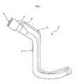
FIG. 1 is an appearance view of a fuel inlet according to an embodiment. -
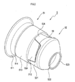
FIG. 2 is a perspective view of a retainer of the embodiment. -
FIG. 3 is a sectional view of a distal end portion of the fuel inlet of the embodiment. -
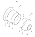
FIG. 4 is an exploded perspective view showing components of the retainer of the embodiment. -
FIG. 5 is a perspective view of a retainer of a comparative example. -
FIG. 6 is a sectional view of a distal end portion of a fuel inlet of the comparative example. - 1... fuel inlet, 2... inlet pipe, 3... breather tube, 5... retainer, 21... filler portion, 31... distal end portion, 51... first component, 52... second component, 53...air vent hole, 514...thread, 523...restriction hole
- Hereinafter, an embodiment to which the present invention is applied will be described with reference to the drawings.
- As shown in
FIG. 1 , a fuel inlet 1 of the present embodiment is a part for automobile, which is designed for use to fill fuel into a fuel tank. The fuel inlet 1 comprises aninlet pipe 2 and abreather tube 3. - The
inlet pipe 2 is a cylindrical pipe that forms a fuel supply path to guide fuel (such as gasoline) from a fuel filler port to a fuel tank, and is made of metal in the present embodiment. In a distal end portion of theinlet pipe 2, afiller portion 21 having an enlarged diameter is formed, and a later-describedretainer 5 is inserted and fixed in the filler portion 21 (seeFIG. 2 andFIG. 3 ). An air filter 4 is provided on an outer circumference of a distal end portion of thefiller portion 21. - The
breather tube 3 is a cylindrical pipe that forms an air vent path to guide so-called vapor, which is air containing fuel vapor in the fuel tank, toward a distal end portion of theinlet pipe 2, to thereby reduce an internal pressure of the fuel tank. Thebreather tube 3 is made of metal in the present embodiment. As shown inFIG. 3 , thebreather tube 3 is connected to theinlet pipe 2 such that adistal end portion 31 of thebreather tube 3 penetrates an outer circumference of theinlet pipe 2, and is secured, for example, by brazing. In the present embodiment, thebreather tube 3 is connected obliquely to the inlet pipe 2 (such that thedistal end portion 31 is directed to a downstream side of the fuel supply path). - Also in the
filler portion 21 of theinlet pipe 2, as shown inFIG. 1 andFIG. 2 , theretainer 5 that is a separate component from theinlet pipe 2 is provided. Theretainer 5 is a cylindrical component into which a fuel filling gun is to be inserted, and is made of metal in the present embodiment. Also, as shown inFIG. 3 , theretainer 5 is secured, for example, by welding in a state where a part of theretainer 5 is inserted in thefiller portion 21. Theretainer 5 comprises a thread (helical engaging portion) 514 as an example of an attachment and detachment mechanism to attach and detach a not-shown fuel filler cap, and arestriction hole 523 as an example of a restriction mechanism to restrict a distal end position of the fuel filling gun during refueling. Theretainer 5 further comprises anair vent hole 53 to allow vapor, which is supplied from thebreather tube 3 toward the distal end portion of theinlet pipe 2, to pass therethrough and to be discharged to the outside. - As shown in
FIG. 3 andFIG. 4 , theretainer 5 comprises two separate components, i.e., afirst component 51 and asecond component 52. Thefirst component 51 includes theaforementioned thread 514; thesecond component 52 includes theaforementioned restriction hole 523. A gap between thefirst component 51 and thesecond component 52 is formed to serve as the aforementionedair vent hole 53. - The
first component 51, which is a cylindrical component having openings at bothend portions first component 51 is a component to form a fuel filler port region that is required to have a specified strength, thefirst component 51 is made of a material having a larger sheet thickness (for example, a stainless steel material having a sheet thickness of 1.2 mm) as compared with theinlet pipe 2, or the like. - An outer diameter of the
first component 51 varies in an axial direction of thefirst component 51, whereas positions of central axes of respective outer diameters are constant (i.e., coaxial). Specifically, in thefirst component 51, the end portion (upstream end portion) 511 on an upstream side of the fuel supply path includes a part having an outer diameter larger than an inner diameter of thefiller portion 21. Theupstream end portion 511 is arranged to be exposed outside thefiller portion 21, and forms the fuel filler port through which the fuel filling gun is inserted. Also, an inner circumferential surface of theupstream end portion 511 includes thethread 514. - On the other hand, in the
first component 51, the end portion (downstream end portion) 512 on a downstream side of the fuel supply path is formed in a cylindrical shape having an outer diameter smaller than the inner diameter of the filler portion 21 (particularly, smaller than a sheet thickness of the second component 52). An end surface of thedownstream end portion 512 is formed to be flat over its entire circumference (having a shape cut by a plane perpendicular to the axial direction). - In the
first component 51, amiddle portion 513 located between theupstream end portion 511 and thedownstream end portion 512 is designed in a cylindrical shape having an outer diameter corresponding to the inner diameter of the filler portion 21 (for example, with a dimension that is equal to or slightly smaller than the inner diameter of the filler portion 21). Themiddle portion 513 is inserted into thefiller portion 21, and is secured, for example, by welding, to thefiller portion 21 such that there is no gap over the entire circumference of the distal end portion of thefiller portion 21. - The
second component 52, which is a cylindrical component having openings at bothend portions second component 52 is made of a material having the same sheet thickness and material quality as thefirst component 51. - In the
second component 52, the end portion (an upstream end portion) 521 on an upstream side of the fuel supply path is formed in a cylindrical shape having an inner diameter corresponding to the outer diameter of thedownstream end portion 512 in the first component 51 (for example, with a dimension that is equal to or slightly larger than the outer diameter of the downstream end portion 512). However, theupstream end portion 521 includes cutouts provided at a plurality of positions (three positions in the present example) equally spaced in a circumferential direction, and the cylindrical shape having an entire circumference remains only partially. In other words, theupstream end portion 521 includes projectingportions 524 that project axially toward the first component 51 (toward the upstream side of the fuel supply path) at a plurality of positions (three positions in the present example) equally spaced in the circumferential direction. - On the other hand, in the
second component 52, the end portion (downstream end portion) 522 on the downstream side of the fuel supply path includes arestriction hole 523 through which a distal end of the fuel filling gun is inserted during refueling. Therestriction hole 523, which is designed to have a diameter that is smaller than the inner diameter of thefiller portion 21 and also slightly larger than an outer diameter of the distal end of the fuel filling gun (such that there is some room therebetween), has a function to restrict the distal end position of the fuel filling gun. - The
second component 52 is secured to thefirst component 51, and forms theretainer 5 in conjunction with thefirst component 51. Specifically, theupstream end portion 521 of thesecond component 52 is mounted to externally cover thedownstream end portion 512 of thefirst component 51 and is secured by welding (for example, spot welding) or the like. - The
second component 52 is secured to thefirst component 51 at such a position where the cutouts formed in theupstream end portion 521, each of the cutouts being located between circumferentially adjacent projectingportions 524, are not completely closed by thedownstream end portion 512 of thefirst component 51. Specifically, part of each of the cutouts formed in theupstream end portion 521 is closed by thedownstream end portion 512 of thefirst component 51, and the air vent holes 53, each having a slit-like shape with an axial width of an opening smaller than a circumferential width of the opening, are formed by the gaps between thefirst component 51 and thesecond component 52 at three positions equally spaced in the circumferential direction. Since the vapor from thebreather tube 3 is supplied to the downstream side, from theretainer 5, of the fuel supply path in theinlet pipe 2, the vapor needs to pass (pass through) theretainer 5 in order to be discharged to the outside; the air vent holes 53 are designed to provide a passage for the vapor at that time. - The size of the air vent hole 53 (the width) may be adjustable depending on a relative positional relationship between the
first component 51 and thesecond component 52 in the axial direction of a connecting portion (cylindrical portion) of thefirst component 51 and thesecond component 52. Specifically, it is possible to adjust an opening area of theair vent hole 53 by adjusting a securing position (a position of the aforementioned connecting portion in the axial direction) of thesecond component 52 to thefirst component 51 in a manufacturing process of theretainer 5. That is, it is possible to manufacture theretainer 5 having theair vent hole 53 of a different size using the same components. - Also, a position (an angle position in the circumferential direction around the axial direction of the inlet pipe 2) of the
restriction hole 523 with respect to theinlet pipe 2 may be adjustable according to an orientation (a rotation angle position) in which thesecond component 52 is secured to thefirst component 51. Specifically, it is possible to adjust a position of therestriction hole 523 without changing a position of thethread 514 with respect to theinlet pipe 2 by adjusting the orientation (the rotation angle position) of thesecond component 52 with respect to thefirst component 51 in the manufacturing process of theretainer 5. That is, it is possible to manufacture the fuel inlet 1 having thethread 514 at the same position and therestriction hole 523 at a different position with respect to theinlet pipe 2 using the same components. - Next, a description will be given of an operation of the fuel inlet 1. During refueling with the fuel filling gun, the internal pressure of the fuel tank increases as the amount of fuel in the fuel tank increases, and the vapor or the fuel in the fuel tank is guided through the
breather tube 3 toward the distal end portion of theinlet pipe 2. The vapor that is supplied from thebreather tube 3 toward the distal end portion of theinlet pipe 2 during refueling passes through theair vent hole 53 formed in theretainer 5 and is discharged to the outside. As a result, the internal pressure of the fuel tank is reduced. - When the fuel amount approaches a full level, the fuel together with the vapor sometimes blows out of the
breather tube 3, causing splashes of fuel inside theinlet pipe 2. This leads to a problem that the splashes of fuel caused as above pass through the air vent hole and jump out. In this regard, according to the present embodiment, theair vent hole 53 having a smaller width as compared with a hole formed by punching process, or the like, is formed by securing thesecond component 52 to thefirst component 51 in a closely arranged manner, and thus passage of the splashes of fuel is inhibited. - According to the embodiment detailed as above, the following effects can be obtained.
- (1) According to the fuel inlet 1 of the present embodiment, it is possible to inhibit splashes of fuel caused in the
inlet pipe 2 from jumping out. Specifically, in aretainer 7 as a comparative example shown inFIG. 5 andFIG. 6 , for example, athread 71, arestriction hole 72, and anair vent hole 73 are formed in a single component. Theair vent hole 73, which is formed by punching process so as to penetrate a side face of theretainer 7, has a circular or substantially circular shape. Accordingly, splashes of fuel that have blown out of thebreather tube 3 can easily pass through theair vent hole 73 and jump out. In contrast, theretainer 5 of the present embodiment comprises two separate components, i.e., thefirst component 51 and thesecond component 52, and the gap provided between these components as theair vent hole 53 has a shape with a small width (an elongated shape). In addition, theair vent hole 53 has a widthwise direction perpendicular to an axial direction of theretainer 7. According to the present embodiment, therefore, if splashes are caused in theinlet pipe 2 by, for example, the fuel blowing out of thebreather tube 3, the splashes (vapor) are more likely to hit around theair vent hole 53. As a result, it is possible to inhibit the splashes of fuel from passing through theair vent hole 53 and jumping out, according to the present embodiment. Further, in the case of forming a hole having an extremely small width, for example, by punching process, various problems in manufacturing may occur; according to the present embodiment in which the gap between the two components is configured to function as theair vent hole 53, a hole having a small width can be easily formed. - (2) The
second component 52 is secured to thefirst component 51 so as to externally cover the end portion of thefirst component 51. Accordingly, in a region where theair vent hole 53 is formed, an outer surface of thesecond component 52 is located outer than an outer surface of thefirst component 51 by the sheet thickness of thesecond component 52. That is, when seen from thedistal end portion 31 of the breather tube 3 (the downstream side of the fuel supply path), theair vent hole 53 is hidden by a step formed by thesecond component 52. As described above, a path from thedistal end portion 31 of thebreather tube 3 through theair vent hole 53 to the outside is complicated. Thus, it is possible to inhibit splashes of fuel from around thesecond component 52 from passing through theair vent hole 53. - (3) The size of the
air vent hole 53 is adjusted depending on a securing position of thesecond component 52 to thefirst component 51. Accordingly, it is possible to manufacture the fuel inlet 1 having theair vent hole 53 of a different size without changing the design of thefirst component 51 or thesecond component 52. Specifically, for example, in the case of theretainer 7 of the aforementioned comparative example (seeFIG. 5 andFIG. 6 ), it is required to change the design of the component itself in order to change the size of theair vent hole 73, which leads to large changes, such as redesigning of a die for punching process, and thus leads to increased manufacturing cost. In contrast, according to the present embodiment, it is not required to change the design of thefirst component 51 or thesecond component 52, and only a change in securing position thereof is sufficient. According to the present embodiment as described above, common use of components can be achieved, for example, in the case of redesigning the size of theair vent hole 53 or in the case of manufacturing a plurality of types of the fuel inlets 1, each type having theair vent hole 53 of a different size; thus, the manufacturing cost can be reduced. - (4) The position of the
restriction hole 523 with respect to theinlet pipe 2 is adjusted according to the orientation (the rotation angle position) in which thesecond component 52 is secured to thefirst component 51. Accordingly, it is possible to manufacture the fuel inlet 1 having therestriction hole 523 positioned differently with respect to theinlet pipe 2 without changing the design of thefirst component 51 or thesecond component 52. It is particularly advantageous, according to the present embodiment, that it is possible to change the position of therestriction hole 523 without changing the position of thethread 514 with respect to theinlet pipe 2. Specifically, automobile manufacturers have a desire that the fuel filler cap be specifically oriented (for example, the knob is horizontally oriented) when tightening of the fuel filler cap is completed. In this regard, in a case where thethread 71 and therestriction hole 72 are integrally formed, for example, as in theretainer 7 of the aforementioned comparative example (seeFIG. 5 andFIG. 6 ), if the position of therestriction hole 72 with respect to theinlet pipe 2 is changed, the position of the thread 71 (and thus the orientation of the fuel filler cap when tightening of the fuel filler cap is completed) will be also changed. In addition, any change in design of a component itself leads to increased manufacturing cost. In contrast, according to the present embodiment, it is possible to change the orientation (the rotation angle position) of thesecond component 52 with respect to thefirst component 51 without changing the orientation of thefirst component 51. Accordingly, common use of components can be achieved, for example, in the case of redesigning the position of therestriction hole 523 or in the case of manufacturing a plurality of types of the fuel inlets 1, each type having therestriction hole 523 that is differently positioned; thus, the manufacturing cost can be reduced. Further, the end surface of thedownstream end portion 512 of thefirst component 51 is formed to be flat over its entire circumference, it is possible to maintain the shape of theair vent hole 53 regardless of how the orientation (the rotation angle position) of thesecond component 52 with respect to thefirst component 51 is adjusted. - (5) The configuration, in which the
thread 71 and therestriction hole 72 are integrally formed as in theretainer 7 of the aforementioned comparative example (seeFIG. 5 andFIG. 6 ), requires more drawing steps, and thus requires an annealing step when theretainer 7 is made of stainless steel material. In contrast, according to the present embodiment, drawing steps of the components can be reduced, and thus the annealing step can be omitted even when theretainer 7 is made of stainless steel material. - Although the embodiment of the present invention has been described above, it is to be understood that the present invention should not be limited to the above-described embodiment, and may be practiced in various forms.
- (1) A material employed for the
second component 52 may have a thickness different from that of the material for thefirst component 51. According to such configuration, the material cost and weight of theretainer 5 may be reduced. Specifically, in a case of forming theretainer 5 as a single component, the thickness of theentire retainer 5 needs to be designed according to a region required to have the greatest strength even when the required strength of theretainer 5 varies by part. In contrast, the thickness of theretainer 5 can be made to be different by part by employing materials having different respective thicknesses for thefirst component 51 and thesecond component 52; thus, the material cost and weight of theretainer 5 can be reduced.
Specifically, a material employed for thesecond component 52 may have a smaller thickness than that of a material for thefirst component 51. With such configuration, it is possible to maintain a higher strength in the fuel filler port region where higher strength is generally required, whereas employing a smaller thickness in a region where a required strength is lower as compared with the fuel filler port region. - (2) The
second component 52 may be made of a different material from the material for thefirst component 51. With such configuration, the material cost and weight of theretainer 5 also may be reduced. Specifically, a material (for example, a stainless steel material different from a stainless steel material employed for the first component 51) having a lower strength than the material for thefirst component 51 may be employed for thesecond component 52. - (3) Although the above-described embodiment exemplifies a configuration in which the
breather tube 3 is connected obliquely to the inlet pipe 2 (seeFIG. 3 ), this should not be a limitation, and thebreather tube 3 may be connected perpendicularly to theinlet pipe 2. According to the configuration where thebreather tube 3 is connected obliquely to the inlet pipe 2 (such that thedistal end portion 31 is directed to the downstream side of the fuel supply path), an effect can be achieved that splashes of fuel caused in theinlet pipe 2 are inhibited from jumping out. However, in the above-described embodiment, the gap between thefirst component 51 and thesecond component 52 forms theair vent hole 53; thus, it will be possible to sufficiently inhibit the splashes of fuel from jumping out also with the configuration where thebreather tube 3 is connected perpendicularly to theinlet pipe 2. The configuration where thebreather tube 3 is connected perpendicularly to theinlet pipe 2 has an effect of enabling easier manufacturing as compared with the configuration of oblique connection as in the above-described embodiment. For example, in the configuration where thebreather tube 3 is connected obliquely to theinlet pipe 2, securing of thebreather tube 3 to theinlet pipe 2 by welding is difficult, and needs to be performed by brazing. In contrast, in the configuration where thebreather tube 3 is connected perpendicularly to theinlet pipe 2, the securing can be performed by welding. - (4) Although the air vent holes 53 are formed equally spaced in the circumferential direction in the above-described embodiment, this should not be a limitation, and a part where no air vent hole is formed and a part where an air vent hole is formed may be provided in the circumferential direction. In this case, the part where an air vent hole is formed may be arranged at a position distant from the
distal end portion 31 of the breather tube 3 (for example, a position not facing the distal end portion 31). Such arrangement enables to effectively inhibit the splashes of fuel that have blown out of thebreather tube 3 from passing through the air vent hole. Alternatively, the part where an air vent hole is formed may be arranged vertically upward. Such arrangement enables to inhibit the air vent hole from being closed by the fuel in theinlet pipe 2. - (5) Although the above-described embodiment exemplifies the
air vent hole 53 shaped to extend in the circumferential direction with respect to an axial direction of theretainer 5, this should not be a limitation; for example, theair vent hole 53 may be shaped to extend in the axial direction of theretainer 5. - (6) Although, in the above-described embodiment, the connecting portion (the
downstream end portion 512 and the upstream end portion 521) of thefirst component 51 and thesecond component 52 is formed in a cylindrical shape, and the orientation (the angle position) of thesecond component 52 with respect to thefirst component 51 is freely adjustable, this should not be a limitation. For example, the connecting portion of thefirst component 51 and thesecond component 52 may be formed in a shape other than a circle (for example, a polygonal shape, such as a hexagon or an octagon), to thereby restrict the orientation of thesecond component 52 with respect to thefirst component 51 to a plurality of orientations (rotation angle positions). Such configuration enables easy positioning during manufacturing, and thus enables reduction in product variation and in manufacturing cost. - (7) Elements of the present invention are conceptual, and should not be limited to those in the above-described embodiment. For example, functions that one element has may be divided among a plurality of elements, or functions that a plurality of elements have may be integrated to one element. Also, at least part of the configuration of the above-described embodiment may be replaced with a known configuration that has the same function.
Claims (6)
- A fuel inlet comprising:an inlet pipe configured to form a path to guide fuel to a fuel tank;a breather tube configured to form a path to guide vapor in the fuel tank toward a distal end portion of the inlet pipe; anda retainer provided at a distal end portion of the inlet pipe and comprising:an attachment and detachment mechanism configured to attach and detach a fuel filler cap; a restriction mechanism configured to restrict a distal end position of a fuel filling gun; and an air vent hole configured to allow passage of the vapor that is supplied from the breather tube toward the distal end portion of the inlet pipe,wherein the retainer comprises:a first component that includes the attachment and detachment mechanism; anda second component that is secured to the first component and includes the restriction mechanism, andwherein the air vent hole is a gap formed between the first component and the second component.
- The fuel inlet according to claim 1, wherein the second component is secured to the first component such that the second component externally covers an end portion of the first component.
- The fuel inlet according to claim 1 or claim 2, wherein a size of the air vent hole is adjusted according to a securing position of the second component with respect to the first component.
- The fuel inlet according to any one of claims 1 to 3, wherein a position of the restriction mechanism with respect to the inlet pipe is adjusted according to an orientation in which the second component is secured to the first component.
- The fuel inlet according to any one of claims 1 to 4, wherein a material used for the second component has a thickness different from that of a material for the first component.
- The fuel inlet according to any one of claims 1 to 5, wherein a material used for the second component has a thickness smaller than that of a material for the first component.
Applications Claiming Priority (2)
| Application Number | Priority Date | Filing Date | Title |
|---|---|---|---|
| JP2012227046A JP6154115B2 (en) | 2012-10-12 | 2012-10-12 | Fuel inlet |
| PCT/JP2013/076056 WO2014057815A1 (en) | 2012-10-12 | 2013-09-26 | Fuel inlet |
Publications (2)
| Publication Number | Publication Date |
|---|---|
| EP2907684A1 true EP2907684A1 (en) | 2015-08-19 |
| EP2907684A4 EP2907684A4 (en) | 2016-07-20 |
Family
ID=50477284
Family Applications (1)
| Application Number | Title | Priority Date | Filing Date |
|---|---|---|---|
| EP13845907.8A Withdrawn EP2907684A4 (en) | 2012-10-12 | 2013-09-26 | Fuel inlet |
Country Status (6)
| Country | Link |
|---|---|
| US (1) | US9649930B2 (en) |
| EP (1) | EP2907684A4 (en) |
| JP (1) | JP6154115B2 (en) |
| CN (1) | CN104703832B (en) |
| CA (1) | CA2887269C (en) |
| WO (1) | WO2014057815A1 (en) |
Families Citing this family (12)
| Publication number | Priority date | Publication date | Assignee | Title |
|---|---|---|---|---|
| CN104053599A (en) * | 2011-12-07 | 2014-09-17 | 托莱多成型及模具股份有限公司 | Filler neck for automotive fluid container |
| DE102013211958A1 (en) * | 2013-06-24 | 2014-12-24 | Bayerische Motoren Werke Aktiengesellschaft | Component for filling a liquid in a liquid container |
| EP3083310B1 (en) * | 2013-12-19 | 2019-06-19 | Illinois Tool Works Inc. | Improper fuel nozzle insertion-inhibiting assembly |
| JP6404599B2 (en) * | 2014-05-30 | 2018-10-10 | フタバ産業株式会社 | Refueling retainer |
| JP6179777B2 (en) | 2014-09-12 | 2017-08-16 | トヨタ自動車株式会社 | Filler pipe |
| JP6190347B2 (en) * | 2014-09-25 | 2017-08-30 | 本田技研工業株式会社 | Scooter type vehicle |
| JP6159356B2 (en) * | 2015-03-19 | 2017-07-05 | 豊田合成株式会社 | Fuel supply device |
| US10029560B2 (en) | 2015-03-19 | 2018-07-24 | Toyoda Gosei Co., Ltd. | Fuel supply apparatus |
| JP6500726B2 (en) * | 2015-09-28 | 2019-04-17 | 豊田合成株式会社 | Fuel supply system |
| JP6297079B2 (en) * | 2016-02-16 | 2018-03-20 | 株式会社Fts | Filler pipe |
| JP6297080B2 (en) * | 2016-02-16 | 2018-03-20 | 株式会社Fts | Filler pipe |
| JP2021160447A (en) * | 2020-03-31 | 2021-10-11 | 豊田合成株式会社 | Fuel supply device |
Family Cites Families (17)
| Publication number | Priority date | Publication date | Assignee | Title |
|---|---|---|---|---|
| JPS5553619U (en) * | 1978-10-09 | 1980-04-11 | ||
| JPH0311055Y2 (en) * | 1985-07-15 | 1991-03-18 | ||
| DE3540740A1 (en) * | 1985-11-16 | 1987-05-21 | Porsche Ag | FUEL CONNECTOR FOR A FUEL TANK, ESPECIALLY FOR FUEL VEHICLES |
| JP2529195B2 (en) * | 1985-11-27 | 1996-08-28 | 日産自動車株式会社 | Refueling structure of vehicle fuel tank |
| DE3602844C1 (en) | 1986-01-30 | 1987-01-02 | Temtec Fahrzeugtechnik Entwicklungsgesellschaft Mbh | Aperture ring |
| JP3632610B2 (en) * | 2001-03-26 | 2005-03-23 | 日産自動車株式会社 | Automobile fuel filler structure |
| US7048019B2 (en) * | 2003-09-30 | 2006-05-23 | Shelby Enterprises, Inc. | Fuel filler tube assembly and manufacturing method |
| US7617851B2 (en) * | 2004-05-28 | 2009-11-17 | Ti Group Automotive Systems, L.L.C. | Refueling vapor recovery system |
| JP4895296B2 (en) * | 2007-03-29 | 2012-03-14 | 豊田合成株式会社 | Filler neck |
| JP4894701B2 (en) * | 2007-09-28 | 2012-03-14 | 豊田合成株式会社 | Filler neck |
| JP2010013006A (en) | 2008-07-04 | 2010-01-21 | Futaba Industrial Co Ltd | Fuel inlet |
| CN201633531U (en) * | 2010-03-30 | 2010-11-17 | 重庆长安汽车股份有限公司 | Automobile oil filling pipe assembly capable of preventing fuel oil from entering ventilating pipe |
| CN202006724U (en) * | 2010-09-13 | 2011-10-12 | 可附特汽车零部件制造(北京)有限公司 | Oil filler pipe |
| EP2444268A3 (en) * | 2010-10-21 | 2018-04-11 | Kohler Co. | Closure device for controlling evaporative emmissions from a fuel tank |
| JP5581191B2 (en) * | 2010-12-02 | 2014-08-27 | 株式会社ニフコ | Oiling nozzle guide device |
| CN201941583U (en) * | 2011-01-20 | 2011-08-24 | 常州市宝顿电子机械有限公司 | Oil filling pipe of gasoline motor car |
| JP2012183887A (en) * | 2011-03-04 | 2012-09-27 | Nifco Inc | Guide device for oil filling nozzle |
-
2012
- 2012-10-12 JP JP2012227046A patent/JP6154115B2/en active Active
-
2013
- 2013-09-26 EP EP13845907.8A patent/EP2907684A4/en not_active Withdrawn
- 2013-09-26 US US14/434,487 patent/US9649930B2/en active Active
- 2013-09-26 CA CA2887269A patent/CA2887269C/en active Active
- 2013-09-26 WO PCT/JP2013/076056 patent/WO2014057815A1/en not_active Ceased
- 2013-09-26 CN CN201380052552.0A patent/CN104703832B/en active Active
Also Published As
| Publication number | Publication date |
|---|---|
| JP2014080040A (en) | 2014-05-08 |
| WO2014057815A1 (en) | 2014-04-17 |
| EP2907684A4 (en) | 2016-07-20 |
| CA2887269C (en) | 2016-07-12 |
| CN104703832A (en) | 2015-06-10 |
| CA2887269A1 (en) | 2014-04-17 |
| US9649930B2 (en) | 2017-05-16 |
| JP6154115B2 (en) | 2017-06-28 |
| CN104703832B (en) | 2017-05-24 |
| US20150251532A1 (en) | 2015-09-10 |
Similar Documents
| Publication | Publication Date | Title |
|---|---|---|
| US9649930B2 (en) | Fuel inlet | |
| US10703196B2 (en) | Refueling retainer | |
| US9694675B2 (en) | Fuel supply apparatus | |
| JP2015227112A (en) | Oil supply retainer | |
| US8220508B2 (en) | Fuel filling device | |
| EP2014502B1 (en) | Inner structure of filler neck of fuel filler tube | |
| US20160272063A1 (en) | Fuel supply apparatus | |
| JP4924366B2 (en) | Fuel supply system | |
| US10792976B2 (en) | Vehicle cabin air register | |
| JP2009101854A (en) | Refueling port device for vehicle fuel tank | |
| EP3187356B1 (en) | Fuel tank check valve | |
| WO2012120983A1 (en) | Guide device for fuel filling nozzle | |
| US10093175B2 (en) | Fueling device | |
| US10407295B2 (en) | Fuel supply apparatus | |
| US20160075230A1 (en) | Filler pipe | |
| US7549508B2 (en) | Muffler | |
| EP1775436B1 (en) | Exhaust system | |
| WO2021131384A1 (en) | Muffler valve and muffler | |
| JP2012131408A (en) | Fuel tank | |
| JP6614004B2 (en) | Fuel supply device | |
| JP6159356B2 (en) | Fuel supply device | |
| JP6337814B2 (en) | Fuel supply device | |
| JP6809384B2 (en) | Fuel supply device | |
| JP2009051460A (en) | Fuel tank | |
| JP2007309303A (en) | Resin-made throttle body |
Legal Events
| Date | Code | Title | Description |
|---|---|---|---|
| PUAI | Public reference made under article 153(3) epc to a published international application that has entered the european phase |
Free format text: ORIGINAL CODE: 0009012 |
|
| 17P | Request for examination filed |
Effective date: 20150501 |
|
| AK | Designated contracting states |
Kind code of ref document: A1 Designated state(s): AL AT BE BG CH CY CZ DE DK EE ES FI FR GB GR HR HU IE IS IT LI LT LU LV MC MK MT NL NO PL PT RO RS SE SI SK SM TR |
|
| AX | Request for extension of the european patent |
Extension state: BA ME |
|
| DAX | Request for extension of the european patent (deleted) | ||
| RA4 | Supplementary search report drawn up and despatched (corrected) |
Effective date: 20160616 |
|
| RIC1 | Information provided on ipc code assigned before grant |
Ipc: B60K 15/04 20060101AFI20160610BHEP Ipc: F02M 37/00 20060101ALI20160610BHEP Ipc: B60K 15/035 20060101ALI20160610BHEP Ipc: B60K 15/03 20060101ALI20160610BHEP |
|
| RAP1 | Party data changed (applicant data changed or rights of an application transferred) |
Owner name: FUTABA INDUSTRIAL CO., LTD. |
|
| RIN1 | Information on inventor provided before grant (corrected) |
Inventor name: OZAKI, YUKIO Inventor name: KATO, MAKOTO |
|
| GRAP | Despatch of communication of intention to grant a patent |
Free format text: ORIGINAL CODE: EPIDOSNIGR1 |
|
| INTG | Intention to grant announced |
Effective date: 20170321 |
|
| STAA | Information on the status of an ep patent application or granted ep patent |
Free format text: STATUS: THE APPLICATION IS DEEMED TO BE WITHDRAWN |
|
| 18D | Application deemed to be withdrawn |
Effective date: 20170801 |