EP2907668A1 - Liquid discharge device and control method of belt cleaning unit - Google Patents
Liquid discharge device and control method of belt cleaning unit Download PDFInfo
- Publication number
- EP2907668A1 EP2907668A1 EP15155472.2A EP15155472A EP2907668A1 EP 2907668 A1 EP2907668 A1 EP 2907668A1 EP 15155472 A EP15155472 A EP 15155472A EP 2907668 A1 EP2907668 A1 EP 2907668A1
- Authority
- EP
- European Patent Office
- Prior art keywords
- transport belt
- wiper blade
- belt
- liquid discharge
- transport
- Prior art date
- Legal status (The legal status is an assumption and is not a legal conclusion. Google has not performed a legal analysis and makes no representation as to the accuracy of the status listed.)
- Granted
Links
- 238000004140 cleaning Methods 0.000 title claims abstract description 119
- 239000007788 liquid Substances 0.000 title claims abstract description 68
- 238000000034 method Methods 0.000 title claims description 13
- 238000011144 upstream manufacturing Methods 0.000 claims abstract description 12
- 238000007639 printing Methods 0.000 claims description 23
- 230000032258 transport Effects 0.000 abstract description 219
- 239000012790 adhesive layer Substances 0.000 description 14
- 230000015556 catabolic process Effects 0.000 description 7
- 238000006731 degradation reaction Methods 0.000 description 7
- 239000004744 fabric Substances 0.000 description 7
- 238000007641 inkjet printing Methods 0.000 description 5
- 230000008859 change Effects 0.000 description 4
- 238000004804 winding Methods 0.000 description 4
- 230000014509 gene expression Effects 0.000 description 3
- 238000007790 scraping Methods 0.000 description 3
- 229920000742 Cotton Polymers 0.000 description 2
- 238000010521 absorption reaction Methods 0.000 description 2
- 230000009471 action Effects 0.000 description 2
- 230000000694 effects Effects 0.000 description 2
- 239000000835 fiber Substances 0.000 description 2
- 229920000728 polyester Polymers 0.000 description 2
- -1 silk Polymers 0.000 description 2
- 244000025254 Cannabis sativa Species 0.000 description 1
- 235000012766 Cannabis sativa ssp. sativa var. sativa Nutrition 0.000 description 1
- 235000012765 Cannabis sativa ssp. sativa var. spontanea Nutrition 0.000 description 1
- 239000004677 Nylon Substances 0.000 description 1
- 230000008901 benefit Effects 0.000 description 1
- 235000009120 camo Nutrition 0.000 description 1
- 235000005607 chanvre indien Nutrition 0.000 description 1
- 238000007598 dipping method Methods 0.000 description 1
- 238000007599 discharging Methods 0.000 description 1
- 230000007613 environmental effect Effects 0.000 description 1
- 239000011487 hemp Substances 0.000 description 1
- 239000004615 ingredient Substances 0.000 description 1
- 238000004519 manufacturing process Methods 0.000 description 1
- 230000007246 mechanism Effects 0.000 description 1
- 239000000203 mixture Substances 0.000 description 1
- 229920001778 nylon Polymers 0.000 description 1
- 230000003287 optical effect Effects 0.000 description 1
- 238000010020 roller printing Methods 0.000 description 1
- 238000007650 screen-printing Methods 0.000 description 1
- 239000002904 solvent Substances 0.000 description 1
- 230000007480 spreading Effects 0.000 description 1
- 238000003892 spreading Methods 0.000 description 1
- 239000000126 substance Substances 0.000 description 1
- 239000004753 textile Substances 0.000 description 1
- XLYOFNOQVPJJNP-UHFFFAOYSA-N water Substances O XLYOFNOQVPJJNP-UHFFFAOYSA-N 0.000 description 1
- 239000002759 woven fabric Substances 0.000 description 1
Images



Classifications
-
- B—PERFORMING OPERATIONS; TRANSPORTING
- B41—PRINTING; LINING MACHINES; TYPEWRITERS; STAMPS
- B41J—TYPEWRITERS; SELECTIVE PRINTING MECHANISMS, i.e. MECHANISMS PRINTING OTHERWISE THAN FROM A FORME; CORRECTION OF TYPOGRAPHICAL ERRORS
- B41J11/00—Devices or arrangements of selective printing mechanisms, e.g. ink-jet printers or thermal printers, for supporting or handling copy material in sheet or web form
- B41J11/007—Conveyor belts or like feeding devices
-
- B—PERFORMING OPERATIONS; TRANSPORTING
- B41—PRINTING; LINING MACHINES; TYPEWRITERS; STAMPS
- B41J—TYPEWRITERS; SELECTIVE PRINTING MECHANISMS, i.e. MECHANISMS PRINTING OTHERWISE THAN FROM A FORME; CORRECTION OF TYPOGRAPHICAL ERRORS
- B41J29/00—Details of, or accessories for, typewriters or selective printing mechanisms not otherwise provided for
- B41J29/17—Cleaning arrangements
Definitions
- the present invention relates to a liquid discharge device including a medium transport unit having a transport belt that transports a medium and a belt cleaning unit that cleans the transport belt, and a control method of the belt cleaning unit that is used when the liquid discharge device is used.2.
- a screen printing device and a roller printing device in which plates of each color are prepared for each drawing pattern to be printed have been widely used as a device that performs printing on a fabric such as cotton, silk, and polyester.
- an ink jet printing device that can print on fabric without using a plate and thereby can cope with job shop type production is spreading rapidly.
- an ink jet printing device including a medium transport unit having a transport belt that transports a medium by attaching the medium thereto by an adhesive layer formed on a surface thereof and a belt cleaning unit that cleans the transport belt.
- JP-A-2004-137032 discloses a belt cleaning device including a blade and an absorption roller.
- JP-A-2004-137033 discloses a belt cleaning device including a blade and a cleaning roller (absorption roller).
- JP-A-2005-219334 discloses a cleaning system including a cleaning roller.
- the blades and the rollers disclosed in JP-A-2004-137032 , JP-A-2004-137033 , and JP-A-2005-219334 are provided in a fixed state. In other words, the blades and the rollers are pressure-contacted to the belt at all times not only during printing but also during stoppage of printing.
- a concave portion may be formed on the surface of the transport belt, and in particular, the concave portion is noticeable in a transport belt having an adhesive layer on the surface of the transport belt.
- a medium rises from a support surface of the transport belt and degradation of print quality and transport failure may occur due to the rise of the medium.
- the cleaning tool is detached from the transport belt and the pressure contact by the cleaning tool is released, the concave portion on the transport belt can be reduced.
- the cleaning tool is detached from the transport belt, droplets used for cleaning remain on the transport belt. Therefore, if movement of the transport belt is restarted in this state, the droplets remaining on the transport belt attach to the medium and stain the medium.
- An advantage of some aspects of the invention is to reduce the stains of the medium caused when the droplets, which remain on the transport belt where the pressure contact by the cleaning tool is released, attach to the medium.
- a liquid discharge device includes a medium transport unit including a transport belt that transports a medium and a belt cleaning unit that cleans the transport belt.
- the belt cleaning unit includes a first wiper blade located on an upstream side in a belt moving direction and a second wiper blade located on a downstream side in the belt moving direction in a cleaning area of the transport belt. At least the first wiper blade is configured to be attachable to and detachable from the transport belt.
- the expression “attachable to” includes “contactable with”
- the expression “detachable from” includes “removable from contact with”
- like expressions should be interpreted accordingly. There is no requirement for the wiper blade(s) to be fixed to the belt.
- the second wiper blade is provided in the downstream of the first wiper blade that is attachable to and detachable from the transport belt, so that it is possible to reduce stains of the medium caused when droplets, which remain on the transport belt where a pressure contact of the first wiper blade is released, attach to the medium.
- a contact angle of the first wiper blade with respect to a surface of the transport belt is set to greater than a contact angle of the second wiper blade with respect to the surface of the transport belt.
- an area where the first wiper blade is in contact with the transport belt is smaller than an area where the second wiper blade is in contact with the transport belt, and a pressure contact force by which the first wiper blade is pressure-contacted to the transport belt is greater than a pressure contact force by which the second wiper blade is pressure-contacted to the transport belt. Therefore, while the transport belt is moving, a cleaning power of the first wiper blade which is first applied to the transport belt in the moving direction is stronger than that of the second wiper blade which is next applied to the transport belt. On the other hand, while the transport belt stops, a concave portion easily occurs on the surface of the transport belt in the contact region with the first wiper blade whose contact area is small and pressure contact force is large.
- the concave portion on the surface of the transport belt it is possible to reduce the generation of the concave portion on the surface of the transport belt by detaching the first wiper blade from the transport belt.
- the pressure contact force is small at the contact region with the second wiper blade, so that the concave portion on the surface of the transport belt is difficult to occur.
- the concave portion is very small, so that the risk of, for example, degradation of print quality and occurrence of transport failure due to the concave portion on the surface of the transport belt is very small.
- the belt cleaning unit includes a control unit that controls an attaching/detaching operation of the first wiper blade to and from the transport belt, and the control unit can control the time when the first wiper blade attached to the transport belt starts detaching from the transport belt after the transport belt stops.
- the control unit that controls the attaching/detaching operation of the first wiper blade to and from the transport belt is provided, so that it is possible to control switching between attaching and detaching of the first wiper blade and the timing to perform the attaching and the detaching of the first wiper blade. Further, the control unit can detach the first wiper blade attached to the transport belt after a predetermined time (for example, about 30 minutes or less) elapses after the transport belt stops. Therefore, it is possible to reduce a risk that the droplets remain on the transport belt, which cause a problem when the first wiper blade is detached immediately after the transport belt stops.
- a predetermined time for example, about 30 minutes or less
- the concave portion on the surface of the transport belt is difficult to occur, so that the risk of, for example, degradation of print quality and occurrence of transport failure due to the concave portion on the surface of the transport belt is very small.
- control unit can control the first wiper blade so that when the stopped transport belt starts moving, the first wiper blade detached from the transport belt comes into contact with the transport belt before the transport belt starts moving.
- the droplets which remain in the contact region of the first wiper blade due to the detachment of the first wiper blade, are prevented from directly moving downstream when the movement of the transport belt is started.
- the remaining droplets are divided into droplets in an upstream position of the first wiper blade and droplets in a downstream position of the first wiper blade, so that the number of droplets that reach the contact region of the second wiper blade located at a downstream position in the belt moving direction becomes small.
- a cleaning brush is provided at a position on an upstream side of the first wiper blade in the belt moving direction, and the cleaning brush is configured to be attachable to and detachable from the transport belt.
- the cleaning brush works on them and removes most of them. Then, the reduced stains along with the droplets reach the contact region of the first wiper blade located at a downstream position in the belt moving direction. Therefore, the amount of stains remaining after the cleaning of the first wiper blade and the second wiper blade is reduced, so that the risk of stains to the medium is very small.
- the belt cleaning unit includes a control unit that controls an attaching/detaching operation of the cleaning brush to and from the transport belt.
- the control unit that controls the attaching/detaching operation of the cleaning brush to and from the transport belt is provided, so that it is possible to control switching between attaching and detaching of the cleaning brush and the timing to perform the attaching and the detaching of the cleaning brush. Therefore, when the transport belt stops, it is possible to perform control so that the cleaning brush is first detached from the transport belt and then the first wiper blade is detached from the transport belt. Thereby, it is possible to reduce the chance where the stains remaining on the transport belt in the contact region of the cleaning brush directly reach the contract region of the first wiper blade when the transport belt starts moving.
- the second wiper blade is configured to be attachable to and detachable from the transport belt.
- the concave portion on an adhesive layer on the surface of the transport belt which is generated when the second wiper blade is pressure-contacted to the transport belt for a long time while the transport belt stops, by detaching the second wiper blade from the transport belt. Therefore, it is possible to further reduce, for example, the degradation of print quality and the occurrence of transport failure due to the concave portion on the adhesive layer by combining the above operation with the attaching/detaching operation of the first wiper blade.
- the belt cleaning unit includes a control unit that controls an attaching/detaching operation of the second wiper blade to and from the transport belt.
- the control unit that controls the attaching/detaching operation of the second wiper blade to and from the transport belt is provided, so that it is possible to control switching between attaching and detaching of the second wiper blade and the timing to perform the attaching and the detaching of the second wiper blade. Therefore, when the transport belt stops, it is possible to perform control so as to wait until the first wiper blade detaches from the transport belt and then detach the second wiper blade from the transport belt. In this way, it is possible to reduce the chance where the droplets remaining on the transport belt in the contact region of the first wiper blade directly reach the contract region of the second wiper blade when the transport belt starts moving.
- a control method of a belt cleaning unit of a ninth aspect of the invention when controlling a belt cleaning unit that cleans a surface of a transport belt by sequentially operating a first wiper blade located on an upstream side in a belt moving direction and a second wiper blade located on a downstream side in the belt moving direction in a cleaning area for the transport belt that is cyclically transported between a printing area and the cleaning area, the first wiper blade that is attached to the surface of the transport belt while the transport belt is moving is detached from the surface of the transport belt while the transport belt stops.
- the second wiper blade is provided in the downstream of the first wiper blade, so that it is possible to reduce stains of the medium caused when droplets remaining on the transport belt attach to the medium by detaching the first wiper blade from the transport belt while the transport belt stops. Further, it is possible to adjust the timing to detach the first wiper blade by controlling an operation to detach the first wiper blade.
- the liquid discharge device 1 of the first embodiment of the invention is basically configured to include a medium transport unit 3 having a transport belt 9 that transports a medium M by attaching the medium M thereto by an adhesive layer 7 formed on a surface thereof and a belt cleaning unit 5 that cleans the transport belt 9.
- the belt cleaning unit 5 is provided with a first wiper blade 15 located on the upstream side of a belt moving direction D and a second wiper blade 17 located on the downstream side of the belt moving direction D in a cleaning area 13 of the transport belt 9. At least the first wiper blade 15 is configured to be attachable to and detachable from the transport belt 9.
- the liquid discharge device 1A shown in Fig. 1 is an ink jet printing device that uses a fabric as the medium M.
- the "fabric” is a textile product such as a cloth and a woven fabric, which use natural fiber such as cotton, hemp, and silk, chemical fiber such as nylon and polyester, and mixture of these as its original yarn.
- the liquid discharge device 1A is provided with, in addition to the medium transport unit 3 and belt cleaning unit 5 described above, a liquid discharge head 19 that performs printing by discharging ink, which is an example of the liquid, to a surface to be printed of the medium M supplied to the printing area 11, a carriage 23 that reciprocates in a width direction B, which is a scanning direction and which crosses a transport direction A of the medium M, along a carriage guide shaft 21 in a state in which the liquid discharge head 19 is mounted as an example on a lower surface of the carriage 23, a guide roller 27 that guides the medium M, which is peeled off from the transport belt 9 after the printing is performed on the medium M, to a winding unit 25, the winding unit 25 that winds the medium M guided by the guide roller 27, and a sensor 29 configured as an example by a contactless optical sensor or the like that detects a winding state of the medium M by the winding unit 25, the timing when the medium M is peeled off from the transport belt 9, and the like.
- a liquid discharge head 19 that
- the medium transport unit 3 is configured to include the transport belt 9 having an endless belt shape which is cyclically transported between the printing area 11 and the cleaning area 13, a drive roller 31 that transmits a drive force in a rotation direction C as an example to the transport belt 9, and a driven roller 33 which is arranged separately from the drive roller 31 and which stretches and holds the wound transport belt 9 in cooperation with the drive roller 31.
- the drive roller 31 is arranged as an example at a downstream position in the belt moving direction D when the medium M is located in the printing area 11, and the driven roller 33 is arranged as an example at an upstream position in the belt moving direction D.
- the aforementioned adhesive layer 7 to which the medium M is attached and temporarily fixed is provided on the outer surface of the transport belt 9 having an endless belt shape.
- the belt cleaning unit 5 is a member arranged in the cleaning area 13 of the transport belt 9 having an endless belt shape.
- the belt cleaning unit 5 includes, in addition to the first wiper blade 15 and the second wiper blade 17, a cleaning liquid tank 35 that stores a cleaning liquid W and a cleaning brush 37 which is located at an upstream position of the first wiper blade 15 in the belt moving direction D in the cleaning liquid tank 35 and which comes into contact with the surface of the transport belt 9 and removes stains attached to the surface of the transport belt 9 by partially dipping itself into the cleaning liquid W and rotating in a rotation direction C.
- the first wiper blade 15 is arranged at a position downstream of the cleaning brush 37 in the belt moving direction D in the cleaning liquid tank 35.
- the second wiper blade 17 is arranged at a position downstream of the first wiper blade 15 in the belt moving direction D.
- the second wiper blade 17 is arranged in a fixed state and is in contact with the surface of the transport belt 9 at all times not only while the transport belt 9 is moving but also while the transport belt 9 stops (including while the transport belt 9 temporarily stops).
- the first wiper blade 15 is arranged to be attachable to and detachable from the transport belt 9 by a known moving mechanism not shown in the drawings and is configured to be movable between a contact position O at which the first wiper blade 15 comes into contact with the surface of the transport belt 9 and a detached position P at which the first wiper blade 15 is detached from the surface of the transport belt 9.
- the first wiper blade 15 is configured to be linearly movable in the vertical direction Z as an example in the first embodiment.
- a contact angle ⁇ 1 of the first wiper blade 15 with respect to the surface of the transport belt 9 is set to greater than a contact angle ⁇ 2 of the second wiper blade 17 with respect to the surface of the transport belt 9 ( ⁇ 1 > ⁇ 2).
- an area where the first wiper blade 15 is in contact with the transport belt 9 is smaller than an area where the second wiper blade 17 is in contact with the transport belt 9, and a pressure contact force by which the first wiper blade 15 is pressure-contacted to the transport belt 9 is greater than a pressure contact force by which the second wiper blade 17 is pressure-contacted to the transport belt 9. Accordingly, while the transport belt 9 is moving, a cleaning power such as a scraping power of the first wiper blade 15 which is first applied to the transport belt 9 in the moving direction of the belt is stronger than that of the second wiper blade 17 which is next applied to the transport belt 9.
- the first wiper blade 15 with strong cleaning power cleans stains attached to the transport belt 9, and after the first wiper blade 15 performs the cleaning processing, the second wiper blade 17, whose cleaning power such as scraping power is weak, further performs cleaning, so that two stages of cleaning are performed.
- the belt cleaning unit 5 is provided with a control unit 39 that controls an attaching/detaching operation of the first wiper blade 15 to and from the transport belt 9.
- the control unit 39 controls the time when the first wiper blade 15 attached to the transport belt 9 starts detaching from the transport belt 9 after the transport belt 9 stops. Specifically, the control unit 39 controls the time so that the first wiper blade 15 starts detaching after a predetermined time of, for example, about 30 minutes or less, elapses after the transport belt 9 stops.
- the "stop” used for the transport belt 9 in the present specification includes a state in which the printing is completed and the medium M is not present on the transport belt 9 located in the printing area 11 and a state of temporary stop in which the printing is temporarily stopped and the medium M is attached to the transport belt 9 located in the printing area 11.
- the "start” used for the movement of the transport belt 9 means an action to move the transport belt 9 from the state of "stop” described above and also includes an action to restart the movement of the transport belt 9 from the state of "temporary stop” described above.
- the predetermined time is about 30 minutes or less.
- the predetermined time is not limited to "30 minutes”.
- the concave portion may be difficult to occur depending on the thickness and the hardness of the adhesive layer 7, the environmental temperature, and the like, so that in such a case, the predetermined time may be set to a value longer than 30 minutes.
- the control unit 39 controls the first wiper blade 15 so that when the stopped transport belt 9 starts moving, the first wiper blade 15 detached from the transport belt 9 comes into contact with the transport belt 9 before the transport belt 9 starts moving.
- the droplets G which remain on the surface of the transport belt 9 in a contact region of the first wiper blade 15 due to the detachment of the first wiper blade 15, are divided by the contact of the first wiper blade 15 and some of the droplets G can be scraped off by the first wiper blade 15. Thereby, the number of droplets G that move downstream of the first wiper blade 15 in the belt moving direction D is reduced, so that the risk of stains on the medium M is reduced.
- a towel roller 41 is provided at a position facing the driven roller 33 in the medium transport unit 3 at a downstream position of the cleaning liquid tank 35 in the belt moving direction D.
- the towel roller 41 is a roller obtained by applying cloth such as towel cloth to an outer circumference surface of a roller which comes into contact with the surface of the transport belt 9.
- the towel roller 41 may drivenly rotate by coming into contact with the transport belt 9 or may drivingly rotate in a direction opposite to the driven rotation.
- the towel roller 41 may be a non-rotating roller that is only pressure-contacted to the transport belt 9 and does not rotate.
- the cleaning liquid W stored in the cleaning liquid tank 35 may be mere water or a special liquid containing a cleaning ingredient and an ink solvent component.
- the control method of the belt cleaning unit is a control method of the belt cleaning unit 5 arranged in the cleaning area 13 with respect to the transport belt 9 which is cyclically transported between the printing area 11 and the cleaning area 13 and is characterized in that the first wiper blade 15 which is attached to the surface of the transport belt 9 while the transport belt 9 is moving is detached from the surface of the transport belt 9 while the transport belt 9 stops.
- control method of the belt cleaning unit 5 included in the liquid discharge device 1A will be specifically described along with operations of each unit in the belt cleaning unit 5.
- the description will be divided into (A) When the belt is moving, (B) When the belt temporarily stops, (C) When the first wiper blade 15 is detached, (D) When the first wiper blade 15 is attached again, and (E) When the belt restarts moving.
- the transport belt 9 moves right to left in Fig. 2 in the printing area 11, however when the transport belt 9 enters the cleaning area 13, the transport belt 9 moves left to right in Fig. 2 by changing the belt moving direction D.
- the transport belt 9 that enters the cleaning area 13 first comes into contact with the cleaning brush 37 which contains the cleaning liquid W and rotates in the rotation direction C, so that stains such as ink attached to the surface of the transport belt 9 are removed. Subsequently, the droplets G0 that contains the stains attached to the transport belt 9 due to the contact with the cleaning brush 37 are carried to the contact position of the first wiper blade 15 at a downstream position in the belt moving direction D. At the contact position of the first wiper blade 15, the first wiper blade 15 works so as to scrape the surface of the transport belt 9 and removes the droplets G0 and the like attached to the transport belt 9.
- the droplets G1 that are not removed by the first wiper blade 15 are carried to the contact position of the second wiper blade 17 at a position downstream in the belt moving direction D.
- the second wiper blade 17 works so as to stroke the surface of the transport belt 9 and removes the droplets G1 remaining on the transport belt 9.
- the droplets G2 that are not removed by the second wiper blade 17 are carried to the contact position of the towel roller 41 at a position downstream in the belt moving direction D.
- the towel roller 41 works so as to wipe the surface of the transport belt 9 and absorbs and removes stains remaining on the transport belt 9 along with the droplets G2.
- the first wiper blade 15 located at the contact position O is moved to a detached position P.
- a state in which the first wiper blade 15 is attached to the surface of the transport belt 9 for a long time while the transport belt 9 is temporarily stopped is avoided. Therefore, the risk that a concave portion occurs on the adhesive layer 7 when the first wiper blade 15 is caused to come into contact with the surface of the transport belt 9 for a long time is reduced, so that degradation of print quality and occurrence of transport failure due to the concave portion on the adhesive layer 7 are suppressed.
- the first wiper blade 15 standing by at the detached position P is caused to come into contact with the surface of the transport belt 9 again.
- the droplets G0 which remain in the contact region of the first wiper blade 15 due to the detachment of the first wiper blade 15, are prevented from directly moving downstream when the movement of the transport belt 9 is restarted.
- the remaining droplets G0 are divided into two portions: one is in the upstream position of the first wiper blade 15 in the belt moving direction D and the other one is in the downstream position, so that the amount of droplets G0 that reach the contact region of the second wiper blade becomes small, shown as g0 in Figs. 5 and 6 .
- liquid discharge device 1A According to the liquid discharge device 1A according to the first embodiment configured as described above and the control method of the belt cleaning unit performed by using the liquid discharge device 1A, it is possible to reduce the occurrence of a concave portion on the adhesive layer 7 that occurs while the transport belt 9 stops, and thereby it is possible to suppress the degradation of print quality and reduce the transport failure of the medium. Further, it is possible to reduce the stains of the medium M caused when the droplets G, which remain on the transport belt 9 where the pressure contact by the first wiper blade 15 is released, attach to the medium M.
- a liquid discharge device 1B according to the second embodiment is a device in which the cleaning brush 37 that is in contact with the transport belt 9 at all times in the first embodiment can be detached from the transport belt 9 and an attaching/detaching operation of the cleaning brush 37 can be controlled.
- the other configuration is the same as that of the liquid discharge device 1A according to the first embodiment. Therefore, here, the description of the same configuration as that of the first embodiment will be omitted and a configuration newly employed in the second embodiment will be mainly described.
- the cleaning brush 37 whose position with respect to the transport belt 9 is fixed is configured to be attachable to and detachable from the transport belt 9. Further, the control unit 39 which controls the attaching/detaching operation of the first wiper blade 15 controls the attaching/detaching operation of the cleaning brush 37.
- the liquid discharge device 1B according to the second embodiment configured as described above it is also possible to obtain the same functions and effects as those of the liquid discharge device 1A according to the first embodiment described above.
- the cleaning brush 37 works on them and removes most of them. Then, the reduced stains along with the droplets G reach the contact region of the first wiper blade 15 located at a downstream position in the belt moving direction D. Therefore, the amount of stains remaining after the scraping of the first wiper blade 15 is also reduced, so that the risk of stains to the medium M is reduced.
- the control unit 39 can control switching between attaching and detaching of the cleaning brush 37 and the timing to perform the attaching and the detaching of the cleaning brush 37. Therefore, when the transport belt 9 stops, it is possible to independently control each of the cleaning brush 37 and the first wiper blade 15 so that the cleaning brush 37 is first detached from the transport belt 9 and then the first wiper blade 15 is detached from the transport belt 9. In this way, it is possible to reduce the case in which the stains remaining on the transport belt 9 in the contact region of the cleaning brush 37 directly reach the contract region of the first wiper blade 15 when the transport belt 9 starts moving. Alternatively, the cleaning brush 37 and the first wiper 15 may be moved at the same time, or at different times to those described above.
- a liquid discharge device 1C according to the third embodiment is a device in which the second wiper blade 17 that is in contact with the transport belt 9 at all times in the first and second embodiments can be detached from the transport belt 9 and an attaching/detaching operation of the second wiper blade 17 can be controlled.
- the other configuration is the same as that of the liquid discharge device 1A, 1B according to the first or second embodiment described above. Therefore, here, the description of the same configuration as that of the first and second embodiments will be omitted and a configuration newly employed in the third embodiment will be mainly described.
- the second wiper blade 17 whose position with respect to the transport belt 9 is fixed is configured to be attachable to and detachable from the transport belt 9. Further, the control unit 39 which controls the attaching/detaching operation of the first wiper blade 15 controls the attaching/detaching operation of the second wiper blade 17.
- the liquid discharge device 1C according to the third embodiment configured as described above it is also possible to obtain the same functions and effects as those of the liquid discharge device 1A according to the first and second embodiments described above.
- the third embodiment it is possible to reduce the generation of the concave portion on the adhesive layer 7 on the surface of the transport belt 9, which is generated when the second wiper blade 17 is pressure-contacted to the transport belt 9 for a long time while the transport belt 9 stops, by detaching the second wiper blade 17 from the transport belt 9. Therefore, it is possible to further reduce the degradation of print quality and the occurrence of transport failure due to the concave portion on the adhesive layer 7 by combining the above operation with the attaching/detaching operation of the first wiper blade 15.
- control unit 39 can control the attaching/detaching operation of the second wiper blade 17 with respect to the transport belt 9, so that it is possible to control switching between attaching and detaching of the second wiper blade 17 and the timing to perform the attaching and the detaching of the second wiper blade 17. Therefore, when the transport belt 9 stops, it is possible to independently control each of the first wiper blade 15 and the second wiper blade 17 so as to wait until the first wiper blade 15 detaches from the transport belt 9 and then detach the second wiper blade 17 from the transport belt 9.
- the liquid discharge device 1 and the control method of a belt cleaning unit according to the invention basically have the configurations as described above. However, it is of course possible to partially change or remove the configurations without departing from the scope of the invention. For example, as shown by a liquid discharge device 1D according to an embodiment shown in Fig. 9 , it is possible to change the attaching/detaching direction of the first wiper blade 15 from the vertical direction Z to a swinging direction R, so that it is possible to change the movement of the first wiper blade 15 from a linear movement to a curved movement.
- the first wiper blade 15 when configured to be able to swing in the swinging direction R, it is possible to adjust the contact angle ⁇ when the first wiper blade 15 comes into contact with the surface of the transport belt 9 and reverse the tilt direction of the first wiper blade 15 when the movement direction D of the transport belt is reversed.
- the second wiper 17 can be moved in the same way.
- the liquid discharge device 1 according to the invention can be applied not only to the ink jet printing device, but also to an ink jet printer that handles a paper sheet and a film as the medium M and a liquid discharge device that has a so-called line head that does not include the carriage 23.
- the "line head” is a liquid discharge head 19 in which a nozzle area formed in the width direction B crossing the transport direction A of the medium M is configured to be able to cover the entire range in the width direction of a surface to be printed of the medium M.
Landscapes
- Ink Jet (AREA)
- Delivering By Means Of Belts And Rollers (AREA)
- Feeding Of Articles By Means Other Than Belts Or Rollers (AREA)
Abstract
Description
- The present invention relates to a liquid discharge device including a medium transport unit having a transport belt that transports a medium and a belt cleaning unit that cleans the transport belt, and a control method of the belt cleaning unit that is used when the liquid discharge device is used.2. Related Art
- A screen printing device and a roller printing device in which plates of each color are prepared for each drawing pattern to be printed have been widely used as a device that performs printing on a fabric such as cotton, silk, and polyester. Further, in recent years, corresponding to digitalization, an ink jet printing device that can print on fabric without using a plate and thereby can cope with job shop type production is spreading rapidly. Among such ink jet printing devices, there is an ink jet printing device including a medium transport unit having a transport belt that transports a medium by attaching the medium thereto by an adhesive layer formed on a surface thereof and a belt cleaning unit that cleans the transport belt.
-
JP-A-2004-137032 JP-A-2004-137033 JP-A-2005-219334 JP-A-2004-137032 JP-A-2004-137033 JP-A-2005-219334 - However, when a cleaning tool such as the blade and the roller is pressure-contacted to the transport belt for a long time during stoppage of printing (including during temporary stoppage of printing), a concave portion may be formed on the surface of the transport belt, and in particular, the concave portion is noticeable in a transport belt having an adhesive layer on the surface of the transport belt. When such a concave portion is formed, a medium rises from a support surface of the transport belt and degradation of print quality and transport failure may occur due to the rise of the medium. In contrast, during stoppage of printing, if the cleaning tool is detached from the transport belt and the pressure contact by the cleaning tool is released, the concave portion on the transport belt can be reduced. However, if the cleaning tool is detached from the transport belt, droplets used for cleaning remain on the transport belt. Therefore, if movement of the transport belt is restarted in this state, the droplets remaining on the transport belt attach to the medium and stain the medium.
- An advantage of some aspects of the invention is to reduce the stains of the medium caused when the droplets, which remain on the transport belt where the pressure contact by the cleaning tool is released, attach to the medium.
- According to a first aspect of the invention, a liquid discharge device includes a medium transport unit including a transport belt that transports a medium and a belt cleaning unit that cleans the transport belt. The belt cleaning unit includes a first wiper blade located on an upstream side in a belt moving direction and a second wiper blade located on a downstream side in the belt moving direction in a cleaning area of the transport belt. At least the first wiper blade is configured to be attachable to and detachable from the transport belt. In this specification, the expression "attachable to" includes "contactable with", the expression "detachable from" includes "removable from contact with", and like expressions should be interpreted accordingly. There is no requirement for the wiper blade(s) to be fixed to the belt.
- According to this aspect, the second wiper blade is provided in the downstream of the first wiper blade that is attachable to and detachable from the transport belt, so that it is possible to reduce stains of the medium caused when droplets, which remain on the transport belt where a pressure contact of the first wiper blade is released, attach to the medium.
- It is preferable that, in the liquid discharge device according to a second aspect of the invention in the first aspect, a contact angle of the first wiper blade with respect to a surface of the transport belt is set to greater than a contact angle of the second wiper blade with respect to the surface of the transport belt.
- According to this aspect, an area where the first wiper blade is in contact with the transport belt is smaller than an area where the second wiper blade is in contact with the transport belt, and a pressure contact force by which the first wiper blade is pressure-contacted to the transport belt is greater than a pressure contact force by which the second wiper blade is pressure-contacted to the transport belt. Therefore, while the transport belt is moving, a cleaning power of the first wiper blade which is first applied to the transport belt in the moving direction is stronger than that of the second wiper blade which is next applied to the transport belt. On the other hand, while the transport belt stops, a concave portion easily occurs on the surface of the transport belt in the contact region with the first wiper blade whose contact area is small and pressure contact force is large. However, it is possible to reduce the generation of the concave portion on the surface of the transport belt by detaching the first wiper blade from the transport belt. On the other hand, the pressure contact force is small at the contact region with the second wiper blade, so that the concave portion on the surface of the transport belt is difficult to occur. Even when the concave portion occurs, the concave portion is very small, so that the risk of, for example, degradation of print quality and occurrence of transport failure due to the concave portion on the surface of the transport belt is very small.
- It is preferable that, in the liquid discharge device according to a third aspect of the invention in the first or the second aspect, the belt cleaning unit includes a control unit that controls an attaching/detaching operation of the first wiper blade to and from the transport belt, and the control unit can control the time when the first wiper blade attached to the transport belt starts detaching from the transport belt after the transport belt stops.
- According to this aspect, the control unit that controls the attaching/detaching operation of the first wiper blade to and from the transport belt is provided, so that it is possible to control switching between attaching and detaching of the first wiper blade and the timing to perform the attaching and the detaching of the first wiper blade. Further, the control unit can detach the first wiper blade attached to the transport belt after a predetermined time (for example, about 30 minutes or less) elapses after the transport belt stops. Therefore, it is possible to reduce a risk that the droplets remain on the transport belt, which cause a problem when the first wiper blade is detached immediately after the transport belt stops. When the predetermined time is about 30 minutes or less, the concave portion on the surface of the transport belt is difficult to occur, so that the risk of, for example, degradation of print quality and occurrence of transport failure due to the concave portion on the surface of the transport belt is very small.
- It is preferable that, in the liquid discharge device according to a fourth aspect of the invention in the third aspect, the control unit can control the first wiper blade so that when the stopped transport belt starts moving, the first wiper blade detached from the transport belt comes into contact with the transport belt before the transport belt starts moving.
- According to this aspect, the droplets, which remain in the contact region of the first wiper blade due to the detachment of the first wiper blade, are prevented from directly moving downstream when the movement of the transport belt is started. When the first wiper blade comes into contact with the transport belt, the remaining droplets are divided into droplets in an upstream position of the first wiper blade and droplets in a downstream position of the first wiper blade, so that the number of droplets that reach the contact region of the second wiper blade located at a downstream position in the belt moving direction becomes small.
- It is preferable that, in the liquid discharge device according to a fifth aspect of the invention in any one of the first to the fourth aspects, in the cleaning area of the transport belt, a cleaning brush is provided at a position on an upstream side of the first wiper blade in the belt moving direction, and the cleaning brush is configured to be attachable to and detachable from the transport belt.
- According to this aspect, regarding the stains attached to the transport belt due to discharge of liquid, first, the cleaning brush works on them and removes most of them. Then, the reduced stains along with the droplets reach the contact region of the first wiper blade located at a downstream position in the belt moving direction. Therefore, the amount of stains remaining after the cleaning of the first wiper blade and the second wiper blade is reduced, so that the risk of stains to the medium is very small.
- It is preferable that, in the liquid discharge device according to a sixth aspect of the invention in the fifth aspect, the belt cleaning unit includes a control unit that controls an attaching/detaching operation of the cleaning brush to and from the transport belt.
- According to this aspect, the control unit that controls the attaching/detaching operation of the cleaning brush to and from the transport belt is provided, so that it is possible to control switching between attaching and detaching of the cleaning brush and the timing to perform the attaching and the detaching of the cleaning brush. Therefore, when the transport belt stops, it is possible to perform control so that the cleaning brush is first detached from the transport belt and then the first wiper blade is detached from the transport belt. Thereby, it is possible to reduce the chance where the stains remaining on the transport belt in the contact region of the cleaning brush directly reach the contract region of the first wiper blade when the transport belt starts moving.
- It is preferable that, in the liquid discharge device according to a seventh aspect of the invention in any one of the first to the sixth aspects, the second wiper blade is configured to be attachable to and detachable from the transport belt.
- According to this aspect, it is possible to reduce the generation of the concave portion on an adhesive layer on the surface of the transport belt, which is generated when the second wiper blade is pressure-contacted to the transport belt for a long time while the transport belt stops, by detaching the second wiper blade from the transport belt. Therefore, it is possible to further reduce, for example, the degradation of print quality and the occurrence of transport failure due to the concave portion on the adhesive layer by combining the above operation with the attaching/detaching operation of the first wiper blade.
- It is preferable that, in the liquid discharge device according to an eighth aspect of the invention in the seventh aspect, the belt cleaning unit includes a control unit that controls an attaching/detaching operation of the second wiper blade to and from the transport belt.
- According to this aspect, the control unit that controls the attaching/detaching operation of the second wiper blade to and from the transport belt is provided, so that it is possible to control switching between attaching and detaching of the second wiper blade and the timing to perform the attaching and the detaching of the second wiper blade. Therefore, when the transport belt stops, it is possible to perform control so as to wait until the first wiper blade detaches from the transport belt and then detach the second wiper blade from the transport belt. In this way, it is possible to reduce the chance where the droplets remaining on the transport belt in the contact region of the first wiper blade directly reach the contract region of the second wiper blade when the transport belt starts moving.
- According a control method of a belt cleaning unit of a ninth aspect of the invention, when controlling a belt cleaning unit that cleans a surface of a transport belt by sequentially operating a first wiper blade located on an upstream side in a belt moving direction and a second wiper blade located on a downstream side in the belt moving direction in a cleaning area for the transport belt that is cyclically transported between a printing area and the cleaning area, the first wiper blade that is attached to the surface of the transport belt while the transport belt is moving is detached from the surface of the transport belt while the transport belt stops.
- According to this aspect, the second wiper blade is provided in the downstream of the first wiper blade, so that it is possible to reduce stains of the medium caused when droplets remaining on the transport belt attach to the medium by detaching the first wiper blade from the transport belt while the transport belt stops. Further, it is possible to adjust the timing to detach the first wiper blade by controlling an operation to detach the first wiper blade.
- Embodiments of the invention will now be described by way of example only with reference to the accompanying drawings, wherein like numbers reference like elements.
-
Fig. 1 is a schematic side view showing a liquid discharge device according to a first embodiment of the invention. -
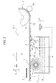
Fig. 2 is a schematic side view showing a belt cleaning unit of the liquid discharge device according to the first embodiment of the invention in a state in which a belt is moving. -
Fig. 3 is a schematic side view showing the belt cleaning unit of the liquid discharge device according to the first embodiment of the invention in a state in which the belt temporarily stops. -
Fig. 4 is a schematic side view showing the belt cleaning unit of the liquid discharge device according to the first embodiment of the invention in a state in which a first wiper blade is detached. -
Fig. 5 is a schematic side view showing the belt cleaning unit of the liquid discharge device according to the first embodiment of the invention in a state in which the first wiper blade comes into contact again. -
Fig. 6 is a schematic side view showing the belt cleaning unit of the liquid discharge device according to the first embodiment of the invention in a state in which the belt starts moving again. -
Fig. 7 is a schematic side view showing a belt cleaning unit of a liquid discharge device according to a second embodiment of the invention in a state in which a cleaning brush is detached. -
Fig. 8 is a schematic side view showing a liquid discharge device according to a third embodiment of the invention in a state in which a second wiper blade is detached. -
Fig. 9 is a schematic side view showing a liquid discharge device according to another embodiment of the invention in a state in which a first wiper blade is detached. - Hereinafter, a liquid discharge device and a control method of a belt cleaning unit of the invention will be described in detail with reference to the attached drawings. In the description below, three embodiments from the first to the third will be described as an example. First, a schematic configuration of the liquid discharge device of the invention and a specific configuration of the belt cleaning unit which is a characteristic configuration of the invention will be described based on the first embodiment. Next, the control method of the belt cleaning unit of the invention will be described along with an operation mode of the belt cleaning unit. Next, configurations and operation modes of the belt cleaning unit of the liquid discharge device according to the second embodiment and the belt cleaning unit of the liquid discharge device according to the third embodiment will be described focusing on differences from the first embodiment.
- The
liquid discharge device 1 of the first embodiment of the invention is basically configured to include amedium transport unit 3 having atransport belt 9 that transports a medium M by attaching the medium M thereto by anadhesive layer 7 formed on a surface thereof and abelt cleaning unit 5 that cleans thetransport belt 9. Thebelt cleaning unit 5 is provided with afirst wiper blade 15 located on the upstream side of a belt moving direction D and asecond wiper blade 17 located on the downstream side of the belt moving direction D in acleaning area 13 of thetransport belt 9. At least thefirst wiper blade 15 is configured to be attachable to and detachable from thetransport belt 9. - First, a schematic configuration of the
liquid discharge device 1A according to the first embodiment will be described with reference toFig. 1 . Theliquid discharge device 1A shown inFig. 1 is an ink jet printing device that uses a fabric as the medium M. Here, the "fabric" is a textile product such as a cloth and a woven fabric, which use natural fiber such as cotton, hemp, and silk, chemical fiber such as nylon and polyester, and mixture of these as its original yarn. Theliquid discharge device 1A is provided with, in addition to themedium transport unit 3 andbelt cleaning unit 5 described above, aliquid discharge head 19 that performs printing by discharging ink, which is an example of the liquid, to a surface to be printed of the medium M supplied to theprinting area 11, acarriage 23 that reciprocates in a width direction B, which is a scanning direction and which crosses a transport direction A of the medium M, along acarriage guide shaft 21 in a state in which theliquid discharge head 19 is mounted as an example on a lower surface of thecarriage 23, aguide roller 27 that guides the medium M, which is peeled off from thetransport belt 9 after the printing is performed on the medium M, to a windingunit 25, the windingunit 25 that winds the medium M guided by theguide roller 27, and asensor 29 configured as an example by a contactless optical sensor or the like that detects a winding state of the medium M by the windingunit 25, the timing when the medium M is peeled off from thetransport belt 9, and the like. - The
medium transport unit 3 is configured to include thetransport belt 9 having an endless belt shape which is cyclically transported between theprinting area 11 and thecleaning area 13, adrive roller 31 that transmits a drive force in a rotation direction C as an example to thetransport belt 9, and a drivenroller 33 which is arranged separately from thedrive roller 31 and which stretches and holds thewound transport belt 9 in cooperation with thedrive roller 31. In the first embodiment shown in the drawings, thedrive roller 31 is arranged as an example at a downstream position in the belt moving direction D when the medium M is located in theprinting area 11, and the drivenroller 33 is arranged as an example at an upstream position in the belt moving direction D. The aforementionedadhesive layer 7 to which the medium M is attached and temporarily fixed is provided on the outer surface of thetransport belt 9 having an endless belt shape. - The
belt cleaning unit 5 is a member arranged in thecleaning area 13 of thetransport belt 9 having an endless belt shape. Thebelt cleaning unit 5 includes, in addition to thefirst wiper blade 15 and thesecond wiper blade 17, a cleaningliquid tank 35 that stores a cleaning liquid W and a cleaningbrush 37 which is located at an upstream position of thefirst wiper blade 15 in the belt moving direction D in the cleaningliquid tank 35 and which comes into contact with the surface of thetransport belt 9 and removes stains attached to the surface of thetransport belt 9 by partially dipping itself into the cleaning liquid W and rotating in a rotation direction C. - The
first wiper blade 15 is arranged at a position downstream of the cleaningbrush 37 in the belt moving direction D in the cleaningliquid tank 35. Thesecond wiper blade 17 is arranged at a position downstream of thefirst wiper blade 15 in the belt moving direction D. Among them, in the present embodiment, thesecond wiper blade 17 is arranged in a fixed state and is in contact with the surface of thetransport belt 9 at all times not only while thetransport belt 9 is moving but also while thetransport belt 9 stops (including while thetransport belt 9 temporarily stops). - On the other hand, the
first wiper blade 15 is arranged to be attachable to and detachable from thetransport belt 9 by a known moving mechanism not shown in the drawings and is configured to be movable between a contact position O at which thefirst wiper blade 15 comes into contact with the surface of thetransport belt 9 and a detached position P at which thefirst wiper blade 15 is detached from the surface of thetransport belt 9. Regarding the moving direction of thefirst wiper blade 15, thefirst wiper blade 15 is configured to be linearly movable in the vertical direction Z as an example in the first embodiment. A contact angle θ1 of thefirst wiper blade 15 with respect to the surface of thetransport belt 9 is set to greater than a contact angle θ2 of thesecond wiper blade 17 with respect to the surface of the transport belt 9 (θ1 > θ2). - Therefore, an area where the
first wiper blade 15 is in contact with thetransport belt 9 is smaller than an area where thesecond wiper blade 17 is in contact with thetransport belt 9, and a pressure contact force by which thefirst wiper blade 15 is pressure-contacted to thetransport belt 9 is greater than a pressure contact force by which thesecond wiper blade 17 is pressure-contacted to thetransport belt 9. Accordingly, while thetransport belt 9 is moving, a cleaning power such as a scraping power of thefirst wiper blade 15 which is first applied to thetransport belt 9 in the moving direction of the belt is stronger than that of thesecond wiper blade 17 which is next applied to thetransport belt 9. Therefore, first, thefirst wiper blade 15 with strong cleaning power cleans stains attached to thetransport belt 9, and after thefirst wiper blade 15 performs the cleaning processing, thesecond wiper blade 17, whose cleaning power such as scraping power is weak, further performs cleaning, so that two stages of cleaning are performed. - The
belt cleaning unit 5 is provided with acontrol unit 39 that controls an attaching/detaching operation of thefirst wiper blade 15 to and from thetransport belt 9. Thecontrol unit 39 controls the time when thefirst wiper blade 15 attached to thetransport belt 9 starts detaching from thetransport belt 9 after thetransport belt 9 stops. Specifically, thecontrol unit 39 controls the time so that thefirst wiper blade 15 starts detaching after a predetermined time of, for example, about 30 minutes or less, elapses after thetransport belt 9 stops. - Here, the "stop" used for the
transport belt 9 in the present specification includes a state in which the printing is completed and the medium M is not present on thetransport belt 9 located in theprinting area 11 and a state of temporary stop in which the printing is temporarily stopped and the medium M is attached to thetransport belt 9 located in theprinting area 11. The "start" used for the movement of thetransport belt 9 means an action to move thetransport belt 9 from the state of "stop" described above and also includes an action to restart the movement of thetransport belt 9 from the state of "temporary stop" described above. The reason why the predetermined time is about 30 minutes or less is because the concave portion of theadhesive layer 7 is difficult to occur even when thefirst wiper blade 15 is caused to come into contact with thetransport belt 9 if the contact time is about 30 minutes or less. Of course, the predetermined time is not limited to "30 minutes". The concave portion may be difficult to occur depending on the thickness and the hardness of theadhesive layer 7, the environmental temperature, and the like, so that in such a case, the predetermined time may be set to a value longer than 30 minutes. - The
control unit 39 controls thefirst wiper blade 15 so that when the stoppedtransport belt 9 starts moving, thefirst wiper blade 15 detached from thetransport belt 9 comes into contact with thetransport belt 9 before thetransport belt 9 starts moving. When the configuration as described above is employed, the droplets G, which remain on the surface of thetransport belt 9 in a contact region of thefirst wiper blade 15 due to the detachment of thefirst wiper blade 15, are divided by the contact of thefirst wiper blade 15 and some of the droplets G can be scraped off by thefirst wiper blade 15. Thereby, the number of droplets G that move downstream of thefirst wiper blade 15 in the belt moving direction D is reduced, so that the risk of stains on the medium M is reduced. - Further, a
towel roller 41 is provided at a position facing the drivenroller 33 in themedium transport unit 3 at a downstream position of the cleaningliquid tank 35 in the belt moving direction D. Thetowel roller 41 is a roller obtained by applying cloth such as towel cloth to an outer circumference surface of a roller which comes into contact with the surface of thetransport belt 9. Thetowel roller 41 may drivenly rotate by coming into contact with thetransport belt 9 or may drivingly rotate in a direction opposite to the driven rotation. Alternatively, thetowel roller 41 may be a non-rotating roller that is only pressure-contacted to thetransport belt 9 and does not rotate. The cleaning liquid W stored in the cleaningliquid tank 35 may be mere water or a special liquid containing a cleaning ingredient and an ink solvent component. - The control method of the belt cleaning unit according to an embodiment of the invention is a control method of the
belt cleaning unit 5 arranged in thecleaning area 13 with respect to thetransport belt 9 which is cyclically transported between theprinting area 11 and thecleaning area 13 and is characterized in that thefirst wiper blade 15 which is attached to the surface of thetransport belt 9 while thetransport belt 9 is moving is detached from the surface of thetransport belt 9 while thetransport belt 9 stops. - Hereinafter, the control method of the
belt cleaning unit 5 included in theliquid discharge device 1A according to the present embodiment will be specifically described along with operations of each unit in thebelt cleaning unit 5. The description will be divided into (A) When the belt is moving, (B) When the belt temporarily stops, (C) When thefirst wiper blade 15 is detached, (D) When thefirst wiper blade 15 is attached again, and (E) When the belt restarts moving. - In a state in which printing is performed and the
transport belt 9 is moved, thetransport belt 9 moves right to left inFig. 2 in theprinting area 11, however when thetransport belt 9 enters thecleaning area 13, thetransport belt 9 moves left to right inFig. 2 by changing the belt moving direction D. - The
transport belt 9 that enters thecleaning area 13 first comes into contact with the cleaningbrush 37 which contains the cleaning liquid W and rotates in the rotation direction C, so that stains such as ink attached to the surface of thetransport belt 9 are removed. Subsequently, the droplets G0 that contains the stains attached to thetransport belt 9 due to the contact with the cleaningbrush 37 are carried to the contact position of thefirst wiper blade 15 at a downstream position in the belt moving direction D. At the contact position of thefirst wiper blade 15, thefirst wiper blade 15 works so as to scrape the surface of thetransport belt 9 and removes the droplets G0 and the like attached to thetransport belt 9. - Subsequently, the droplets G1 that are not removed by the
first wiper blade 15 are carried to the contact position of thesecond wiper blade 17 at a position downstream in the belt moving direction D. At the contact position of thesecond wiper blade 17, thesecond wiper blade 17 works so as to stroke the surface of thetransport belt 9 and removes the droplets G1 remaining on thetransport belt 9. Subsequently, the droplets G2 that are not removed by thesecond wiper blade 17 are carried to the contact position of thetowel roller 41 at a position downstream in the belt moving direction D. At the contact position of thetowel roller 41, thetowel roller 41 works so as to wipe the surface of thetransport belt 9 and absorbs and removes stains remaining on thetransport belt 9 along with the droplets G2. - In a state in which the printing is suspended temporarily and the movement of the
transport belt 9 is stopped temporarily, the rotation of the cleaningbrush 37 is stopped, however, the contact states of the cleaningbrush 37, thefirst wiper blade 15, thesecond wiper blade 17, and thetowel roller 41 do not change. Therefore, there are the droplets G0 at the contact region of thefirst wiper blade 15 and there are the droplets G1 at the contact region of thesecond wiper blade 17. The above state continues for the predetermined time. Thereby, it is possible to reduce a risk that the droplets remain on thetransport belt 9, which cause a problem when thefirst wiper blade 15 is detached immediately after thetransport belt 9 temporarily stops. Thereby, it is possible to reduce a risk that the droplets G0 pass through the contact region of thefirst wiper blade 15. Further, the risk that a concave portion occurs on theadhesive layer 7 is very small if the contact time is about 30 minutes or less as described above. - After the aforementioned predetermined time elapses, the
first wiper blade 15 located at the contact position O is moved to a detached position P. Thereby, a state in which thefirst wiper blade 15 is attached to the surface of thetransport belt 9 for a long time while thetransport belt 9 is temporarily stopped is avoided. Therefore, the risk that a concave portion occurs on theadhesive layer 7 when thefirst wiper blade 15 is caused to come into contact with the surface of thetransport belt 9 for a long time is reduced, so that degradation of print quality and occurrence of transport failure due to the concave portion on theadhesive layer 7 are suppressed. - Before the movement of the
transport belt 9 is restarted in association with restart of printing, thefirst wiper blade 15 standing by at the detached position P is caused to come into contact with the surface of thetransport belt 9 again. Thereby, the droplets G0, which remain in the contact region of thefirst wiper blade 15 due to the detachment of thefirst wiper blade 15, are prevented from directly moving downstream when the movement of thetransport belt 9 is restarted. When thefirst wiper blade 15 comes into contact with thetransport belt 9 again, the remaining droplets G0 are divided into two portions: one is in the upstream position of thefirst wiper blade 15 in the belt moving direction D and the other one is in the downstream position, so that the amount of droplets G0 that reach the contact region of the second wiper blade becomes small, shown as g0 inFigs. 5 and6 . - When the
transport belt 9 is moved again in the moving direction D after thefirst wiper blade 15 comes into contact with thetransport belt 9 again, the droplets g0 which is divided into two and reduced and the droplets G1 remaining at the contact region of thesecond wiper blade 17 are removed by thesecond wiper blade 17. Thereafter, in the same manner as in the aforementioned (A), when the belt is moving, the droplets G2 containing stains that are not removed by thesecond wiper blade 17 are carried to the contact region of thetowel roller 41 and removed by thetowel roller 41. - According to the
liquid discharge device 1A according to the first embodiment configured as described above and the control method of the belt cleaning unit performed by using theliquid discharge device 1A, it is possible to reduce the occurrence of a concave portion on theadhesive layer 7 that occurs while thetransport belt 9 stops, and thereby it is possible to suppress the degradation of print quality and reduce the transport failure of the medium. Further, it is possible to reduce the stains of the medium M caused when the droplets G, which remain on thetransport belt 9 where the pressure contact by thefirst wiper blade 15 is released, attach to the medium M. - A
liquid discharge device 1B according to the second embodiment is a device in which the cleaningbrush 37 that is in contact with thetransport belt 9 at all times in the first embodiment can be detached from thetransport belt 9 and an attaching/detaching operation of the cleaningbrush 37 can be controlled. The other configuration is the same as that of theliquid discharge device 1A according to the first embodiment. Therefore, here, the description of the same configuration as that of the first embodiment will be omitted and a configuration newly employed in the second embodiment will be mainly described. - In the second embodiment, the cleaning
brush 37 whose position with respect to thetransport belt 9 is fixed is configured to be attachable to and detachable from thetransport belt 9. Further, thecontrol unit 39 which controls the attaching/detaching operation of thefirst wiper blade 15 controls the attaching/detaching operation of the cleaningbrush 37. When using theliquid discharge device 1B according to the second embodiment configured as described above, it is also possible to obtain the same functions and effects as those of theliquid discharge device 1A according to the first embodiment described above. - Regarding the stains attached to the
transport belt 9 by the execution of printing, first, the cleaningbrush 37 works on them and removes most of them. Then, the reduced stains along with the droplets G reach the contact region of thefirst wiper blade 15 located at a downstream position in the belt moving direction D. Therefore, the amount of stains remaining after the scraping of thefirst wiper blade 15 is also reduced, so that the risk of stains to the medium M is reduced. - In the second embodiment, the
control unit 39 can control switching between attaching and detaching of the cleaningbrush 37 and the timing to perform the attaching and the detaching of the cleaningbrush 37. Therefore, when thetransport belt 9 stops, it is possible to independently control each of the cleaningbrush 37 and thefirst wiper blade 15 so that the cleaningbrush 37 is first detached from thetransport belt 9 and then thefirst wiper blade 15 is detached from thetransport belt 9. In this way, it is possible to reduce the case in which the stains remaining on thetransport belt 9 in the contact region of the cleaningbrush 37 directly reach the contract region of thefirst wiper blade 15 when thetransport belt 9 starts moving. Alternatively, the cleaningbrush 37 and thefirst wiper 15 may be moved at the same time, or at different times to those described above. - A
liquid discharge device 1C according to the third embodiment is a device in which thesecond wiper blade 17 that is in contact with thetransport belt 9 at all times in the first and second embodiments can be detached from thetransport belt 9 and an attaching/detaching operation of thesecond wiper blade 17 can be controlled. The other configuration is the same as that of theliquid discharge device - In the third embodiment, the
second wiper blade 17 whose position with respect to thetransport belt 9 is fixed is configured to be attachable to and detachable from thetransport belt 9. Further, thecontrol unit 39 which controls the attaching/detaching operation of thefirst wiper blade 15 controls the attaching/detaching operation of thesecond wiper blade 17. When using theliquid discharge device 1C according to the third embodiment configured as described above, it is also possible to obtain the same functions and effects as those of theliquid discharge device 1A according to the first and second embodiments described above. - Further, in the third embodiment, it is possible to reduce the generation of the concave portion on the
adhesive layer 7 on the surface of thetransport belt 9, which is generated when thesecond wiper blade 17 is pressure-contacted to thetransport belt 9 for a long time while thetransport belt 9 stops, by detaching thesecond wiper blade 17 from thetransport belt 9. Therefore, it is possible to further reduce the degradation of print quality and the occurrence of transport failure due to the concave portion on theadhesive layer 7 by combining the above operation with the attaching/detaching operation of thefirst wiper blade 15. - In the third embodiment, the
control unit 39 can control the attaching/detaching operation of thesecond wiper blade 17 with respect to thetransport belt 9, so that it is possible to control switching between attaching and detaching of thesecond wiper blade 17 and the timing to perform the attaching and the detaching of thesecond wiper blade 17. Therefore, when thetransport belt 9 stops, it is possible to independently control each of thefirst wiper blade 15 and thesecond wiper blade 17 so as to wait until thefirst wiper blade 15 detaches from thetransport belt 9 and then detach thesecond wiper blade 17 from thetransport belt 9. In this way, it is possible to reduce the case in which the droplets G remaining on thetransport belt 9 in the contact region of thefirst wiper blade 15 directly reach the contract region of thesecond wiper blade 17 when thetransport belt 9 starts moving. Simultaneous movement and other timings are also possible. - The
liquid discharge device 1 and the control method of a belt cleaning unit according to the invention basically have the configurations as described above. However, it is of course possible to partially change or remove the configurations without departing from the scope of the invention. For example, as shown by aliquid discharge device 1D according to an embodiment shown inFig. 9 , it is possible to change the attaching/detaching direction of thefirst wiper blade 15 from the vertical direction Z to a swinging direction R, so that it is possible to change the movement of thefirst wiper blade 15 from a linear movement to a curved movement. For example, when thefirst wiper blade 15 is configured to be able to swing in the swinging direction R, it is possible to adjust the contact angle θ when thefirst wiper blade 15 comes into contact with the surface of thetransport belt 9 and reverse the tilt direction of thefirst wiper blade 15 when the movement direction D of the transport belt is reversed. This applies to all embodiments. Thesecond wiper 17 can be moved in the same way. - In addition, the
liquid discharge device 1 according to the invention can be applied not only to the ink jet printing device, but also to an ink jet printer that handles a paper sheet and a film as the medium M and a liquid discharge device that has a so-called line head that does not include thecarriage 23. Here, the "line head" is aliquid discharge head 19 in which a nozzle area formed in the width direction B crossing the transport direction A of the medium M is configured to be able to cover the entire range in the width direction of a surface to be printed of the medium M.
Claims (9)
- A liquid discharge device (1) comprising:a transport belt (9) configured to transport a medium (M); anda belt cleaning unit (5) configured to clean the transport belt,wherein the belt cleaning unit includes
a first wiper blade (15) located on an upstream side in a belt moving direction (D) in a cleaning area (13) of the transport belt, and
a second wiper blade (17) located on a downstream side in the belt moving direction, andat least the first wiper blade is attachable to and detachable from the transport belt. - The liquid discharge device according to Claim 1, wherein
a contact angle (θ1) of the first wiper blade with respect to a surface of the transport belt is greater than a contact angle (θ2) of the second wiper blade with respect to the surface of the transport belt. - The liquid discharge device according to Claim 1 or Claim 2,
further comprising a control unit (19) configured to control an attaching/detaching operation of the first wiper blade to and from the transport belt,
wherein the control unit is configured to control time when the first wiper blade attached to the transport belt starts detaching from the transport belt after the transport belt stops. - The liquid discharge device according to Claim 3, wherein
the control unit is configured to control the first wiper blade so that the first wiper blade detached from the transport belt comes into contact with the transport belt before the transport belt starts moving. - The liquid discharge device according to any one of the preceding claims, wherein
in the cleaning area of the transport belt, a cleaning brush (37) is provided at a position on an upstream side of the first wiper blade in the belt moving direction, and
the cleaning brush is attachable to and detachable from the transport belt. - The liquid discharge device according to Claim 5,
further comprising a control unit (19) configured to control an attaching/detaching operation of the cleaning brush to and from the transport belt. - The liquid discharge device according to any one of the preceding claims, wherein
the second wiper blade is attachable to and detachable from the transport belt. - The liquid discharge device according to Claim 7,
further comprising a control unit (19) configured to control an attaching/detaching operation of the second wiper blade to and from the transport belt. - A control method for a belt cleaning unit (5), which controls a belt cleaning unit that cleans a surface of a transport belt (9), the belt cleaning unit having a first wiper blade (15) located on an upstream side in a belt moving direction and a second wiper blade (17) located on a downstream side in the belt moving direction in a cleaning area (13) for the transport belt that is cyclically transported between a printing area (11) and the cleaning area, the control method comprising:detaching the first wiper blade, which is attached to the surface of the transport belt while the transport belt is moving from the surface of the transport belt when the transport belt has stopped.
Applications Claiming Priority (1)
| Application Number | Priority Date | Filing Date | Title |
|---|---|---|---|
| JP2014028245A JP6307918B2 (en) | 2014-02-18 | 2014-02-18 | Control method for liquid ejection device and belt cleaning unit |
Publications (2)
| Publication Number | Publication Date |
|---|---|
| EP2907668A1 true EP2907668A1 (en) | 2015-08-19 |
| EP2907668B1 EP2907668B1 (en) | 2020-02-12 |
Family
ID=52574040
Family Applications (1)
| Application Number | Title | Priority Date | Filing Date |
|---|---|---|---|
| EP15155472.2A Active EP2907668B1 (en) | 2014-02-18 | 2015-02-17 | Liquid discharge device and control method of belt cleaning unit |
Country Status (2)
| Country | Link |
|---|---|
| EP (1) | EP2907668B1 (en) |
| JP (1) | JP6307918B2 (en) |
Cited By (3)
| Publication number | Priority date | Publication date | Assignee | Title |
|---|---|---|---|---|
| CN110816086A (en) * | 2020-01-09 | 2020-02-21 | 广东希望高科数字技术有限公司 | Cleaning system of conveying mechanism of digital printing machine |
| US20220032663A1 (en) * | 2020-07-31 | 2022-02-03 | Seiko Epson Corporation | Recording device and method for reversely transporting recording medium |
| CN116461227A (en) * | 2022-01-18 | 2023-07-21 | 精工爱普生株式会社 | Liquid discharge device, method for controlling liquid discharge device, and program |
Families Citing this family (4)
| Publication number | Priority date | Publication date | Assignee | Title |
|---|---|---|---|---|
| JP7338256B2 (en) * | 2019-06-18 | 2023-09-05 | コニカミノルタ株式会社 | Recording medium conveying device and image forming device |
| JP7384009B2 (en) * | 2019-11-29 | 2023-11-21 | コニカミノルタ株式会社 | Recording medium transport device and image forming device |
| JP7415660B2 (en) * | 2020-02-28 | 2024-01-17 | コニカミノルタ株式会社 | Recording medium transport device and image recording device |
| JP2024071807A (en) * | 2022-11-15 | 2024-05-27 | コニカミノルタ株式会社 | Printing method |
Citations (6)
| Publication number | Priority date | Publication date | Assignee | Title |
|---|---|---|---|---|
| JP2004137032A (en) | 2002-10-17 | 2004-05-13 | Konica Minolta Holdings Inc | Cleaning device for conveying belt, and image forming device |
| JP2004137033A (en) | 2002-10-17 | 2004-05-13 | Konica Minolta Holdings Inc | Cleaning device for conveying belt, and ink jet recording device |
| JP2005219334A (en) | 2004-02-05 | 2005-08-18 | Konica Minolta Holdings Inc | Cleaning system |
| JP2007076863A (en) * | 2005-09-15 | 2007-03-29 | Fuji Xerox Co Ltd | Liquid droplet discharge device |
| US20120001984A1 (en) * | 2010-06-30 | 2012-01-05 | Brother Kogyo Kabushiki Kaisha | Inkjet recording apparatus |
| JP2012116619A (en) * | 2010-11-30 | 2012-06-21 | Konica Minolta Ij Technologies Inc | Recording medium conveying device and image recording device |
Family Cites Families (3)
| Publication number | Priority date | Publication date | Assignee | Title |
|---|---|---|---|---|
| JP4696930B2 (en) * | 2006-01-24 | 2011-06-08 | 富士ゼロックス株式会社 | Droplet discharge device |
| JP4760941B2 (en) * | 2009-03-26 | 2011-08-31 | ブラザー工業株式会社 | Inkjet recording device |
| US8727518B2 (en) * | 2012-06-11 | 2014-05-20 | Xerox Corporation | Method for positioning a metering blade with reference to roller and blade wear |
-
2014
- 2014-02-18 JP JP2014028245A patent/JP6307918B2/en not_active Expired - Fee Related
-
2015
- 2015-02-17 EP EP15155472.2A patent/EP2907668B1/en active Active
Patent Citations (6)
| Publication number | Priority date | Publication date | Assignee | Title |
|---|---|---|---|---|
| JP2004137032A (en) | 2002-10-17 | 2004-05-13 | Konica Minolta Holdings Inc | Cleaning device for conveying belt, and image forming device |
| JP2004137033A (en) | 2002-10-17 | 2004-05-13 | Konica Minolta Holdings Inc | Cleaning device for conveying belt, and ink jet recording device |
| JP2005219334A (en) | 2004-02-05 | 2005-08-18 | Konica Minolta Holdings Inc | Cleaning system |
| JP2007076863A (en) * | 2005-09-15 | 2007-03-29 | Fuji Xerox Co Ltd | Liquid droplet discharge device |
| US20120001984A1 (en) * | 2010-06-30 | 2012-01-05 | Brother Kogyo Kabushiki Kaisha | Inkjet recording apparatus |
| JP2012116619A (en) * | 2010-11-30 | 2012-06-21 | Konica Minolta Ij Technologies Inc | Recording medium conveying device and image recording device |
Cited By (5)
| Publication number | Priority date | Publication date | Assignee | Title |
|---|---|---|---|---|
| CN110816086A (en) * | 2020-01-09 | 2020-02-21 | 广东希望高科数字技术有限公司 | Cleaning system of conveying mechanism of digital printing machine |
| CN110816086B (en) * | 2020-01-09 | 2020-04-28 | 广东希望高科数字技术有限公司 | Cleaning system of conveying mechanism of digital printing machine |
| US20220032663A1 (en) * | 2020-07-31 | 2022-02-03 | Seiko Epson Corporation | Recording device and method for reversely transporting recording medium |
| US11648786B2 (en) * | 2020-07-31 | 2023-05-16 | Seiko Epson Corporation | Recording device and method for reversely transporting recording medium |
| CN116461227A (en) * | 2022-01-18 | 2023-07-21 | 精工爱普生株式会社 | Liquid discharge device, method for controlling liquid discharge device, and program |
Also Published As
| Publication number | Publication date |
|---|---|
| JP6307918B2 (en) | 2018-04-11 |
| JP2015150820A (en) | 2015-08-24 |
| EP2907668B1 (en) | 2020-02-12 |
Similar Documents
| Publication | Publication Date | Title |
|---|---|---|
| EP2907668B1 (en) | Liquid discharge device and control method of belt cleaning unit | |
| EP3310696B1 (en) | Liquid ejecting apparatus, and cleaning method of transport belt of liquid ejecting apparatus | |
| EP3052322B1 (en) | Recording apparatus and cleaning method of transport belt | |
| US10189279B2 (en) | Liquid discharge apparatus and medium flattening method | |
| CN104859303A (en) | Liquid Discharge Device And Media Pretreatment Method | |
| JP5208833B2 (en) | Head cleaning method and apparatus | |
| JP5638972B2 (en) | Liquid ejection device | |
| EP1559568B1 (en) | Image recording apparatus | |
| JP5281537B2 (en) | Head cleaning apparatus, head cleaning method, and ink jet recording apparatus | |
| KR20150099421A (en) | Gravure printing press | |
| JP6251246B2 (en) | On-demand operation of flexo coating equipment | |
| JP6589422B2 (en) | Liquid ejection device | |
| WO2015064092A1 (en) | Printing device and printing device control method | |
| CN211567324U (en) | Liquid ejecting apparatus | |
| JP2007290186A (en) | Printing machine | |
| EP3922465A1 (en) | Liquid discharge device and method for reading test pattern image by liquid discharge device | |
| JPH08132598A (en) | Blanket cylinder and impression cylinder commonly cleaning apparatus | |
| US12103308B2 (en) | Head cleaning device, head cleaning method, and image forming apparatus | |
| WO2010147143A1 (en) | Cylinder cleaning device | |
| EP3213917A1 (en) | Printer cleaning device | |
| JP2012061614A (en) | Liquid ejection device and liquid ejection method | |
| JP2011016263A (en) | Ink roller in printing machine, blanket cleaning method, and cleaning system therefor | |
| JP2011189691A (en) | Cleaning member for wiping roller of intaglio printing machine and method for shaping cleaning member | |
| JP2025128396A (en) | How to clean an inkjet printer and its head unit | |
| JPS6250148A (en) | Apparatus for supplying washing solution in printing press |
Legal Events
| Date | Code | Title | Description |
|---|---|---|---|
| PUAI | Public reference made under article 153(3) epc to a published international application that has entered the european phase |
Free format text: ORIGINAL CODE: 0009012 |
|
| AK | Designated contracting states |
Kind code of ref document: A1 Designated state(s): AL AT BE BG CH CY CZ DE DK EE ES FI FR GB GR HR HU IE IS IT LI LT LU LV MC MK MT NL NO PL PT RO RS SE SI SK SM TR |
|
| AX | Request for extension of the european patent |
Extension state: BA ME |
|
| 17P | Request for examination filed |
Effective date: 20160219 |
|
| RBV | Designated contracting states (corrected) |
Designated state(s): AL AT BE BG CH CY CZ DE DK EE ES FI FR GB GR HR HU IE IS IT LI LT LU LV MC MK MT NL NO PL PT RO RS SE SI SK SM TR |
|
| STAA | Information on the status of an ep patent application or granted ep patent |
Free format text: STATUS: EXAMINATION IS IN PROGRESS |
|
| 17Q | First examination report despatched |
Effective date: 20190204 |
|
| GRAP | Despatch of communication of intention to grant a patent |
Free format text: ORIGINAL CODE: EPIDOSNIGR1 |
|
| STAA | Information on the status of an ep patent application or granted ep patent |
Free format text: STATUS: GRANT OF PATENT IS INTENDED |
|
| INTG | Intention to grant announced |
Effective date: 20191009 |
|
| GRAS | Grant fee paid |
Free format text: ORIGINAL CODE: EPIDOSNIGR3 |
|
| GRAA | (expected) grant |
Free format text: ORIGINAL CODE: 0009210 |
|
| STAA | Information on the status of an ep patent application or granted ep patent |
Free format text: STATUS: THE PATENT HAS BEEN GRANTED |
|
| AK | Designated contracting states |
Kind code of ref document: B1 Designated state(s): AL AT BE BG CH CY CZ DE DK EE ES FI FR GB GR HR HU IE IS IT LI LT LU LV MC MK MT NL NO PL PT RO RS SE SI SK SM TR |
|
| REG | Reference to a national code |
Ref country code: GB Ref legal event code: FG4D |
|
| REG | Reference to a national code |
Ref country code: CH Ref legal event code: EP |
|
| REG | Reference to a national code |
Ref country code: AT Ref legal event code: REF Ref document number: 1231587 Country of ref document: AT Kind code of ref document: T Effective date: 20200215 |
|
| REG | Reference to a national code |
Ref country code: DE Ref legal event code: R096 Ref document number: 602015046637 Country of ref document: DE |
|
| REG | Reference to a national code |
Ref country code: IE Ref legal event code: FG4D |
|
| PG25 | Lapsed in a contracting state [announced via postgrant information from national office to epo] |
Ref country code: NO Free format text: LAPSE BECAUSE OF FAILURE TO SUBMIT A TRANSLATION OF THE DESCRIPTION OR TO PAY THE FEE WITHIN THE PRESCRIBED TIME-LIMIT Effective date: 20200512 Ref country code: RS Free format text: LAPSE BECAUSE OF FAILURE TO SUBMIT A TRANSLATION OF THE DESCRIPTION OR TO PAY THE FEE WITHIN THE PRESCRIBED TIME-LIMIT Effective date: 20200212 Ref country code: FI Free format text: LAPSE BECAUSE OF FAILURE TO SUBMIT A TRANSLATION OF THE DESCRIPTION OR TO PAY THE FEE WITHIN THE PRESCRIBED TIME-LIMIT Effective date: 20200212 |
|
| REG | Reference to a national code |
Ref country code: LT Ref legal event code: MG4D |
|
| REG | Reference to a national code |
Ref country code: NL Ref legal event code: MP Effective date: 20200212 |
|
| PG25 | Lapsed in a contracting state [announced via postgrant information from national office to epo] |
Ref country code: IS Free format text: LAPSE BECAUSE OF FAILURE TO SUBMIT A TRANSLATION OF THE DESCRIPTION OR TO PAY THE FEE WITHIN THE PRESCRIBED TIME-LIMIT Effective date: 20200612 Ref country code: GR Free format text: LAPSE BECAUSE OF FAILURE TO SUBMIT A TRANSLATION OF THE DESCRIPTION OR TO PAY THE FEE WITHIN THE PRESCRIBED TIME-LIMIT Effective date: 20200513 Ref country code: HR Free format text: LAPSE BECAUSE OF FAILURE TO SUBMIT A TRANSLATION OF THE DESCRIPTION OR TO PAY THE FEE WITHIN THE PRESCRIBED TIME-LIMIT Effective date: 20200212 Ref country code: LV Free format text: LAPSE BECAUSE OF FAILURE TO SUBMIT A TRANSLATION OF THE DESCRIPTION OR TO PAY THE FEE WITHIN THE PRESCRIBED TIME-LIMIT Effective date: 20200212 Ref country code: SE Free format text: LAPSE BECAUSE OF FAILURE TO SUBMIT A TRANSLATION OF THE DESCRIPTION OR TO PAY THE FEE WITHIN THE PRESCRIBED TIME-LIMIT Effective date: 20200212 Ref country code: BG Free format text: LAPSE BECAUSE OF FAILURE TO SUBMIT A TRANSLATION OF THE DESCRIPTION OR TO PAY THE FEE WITHIN THE PRESCRIBED TIME-LIMIT Effective date: 20200512 |
|
| PG25 | Lapsed in a contracting state [announced via postgrant information from national office to epo] |
Ref country code: NL Free format text: LAPSE BECAUSE OF FAILURE TO SUBMIT A TRANSLATION OF THE DESCRIPTION OR TO PAY THE FEE WITHIN THE PRESCRIBED TIME-LIMIT Effective date: 20200212 |
|
| REG | Reference to a national code |
Ref country code: CH Ref legal event code: PL |
|
| REG | Reference to a national code |
Ref country code: BE Ref legal event code: MM Effective date: 20200229 |
|
| PG25 | Lapsed in a contracting state [announced via postgrant information from national office to epo] |
Ref country code: PT Free format text: LAPSE BECAUSE OF FAILURE TO SUBMIT A TRANSLATION OF THE DESCRIPTION OR TO PAY THE FEE WITHIN THE PRESCRIBED TIME-LIMIT Effective date: 20200705 Ref country code: ES Free format text: LAPSE BECAUSE OF FAILURE TO SUBMIT A TRANSLATION OF THE DESCRIPTION OR TO PAY THE FEE WITHIN THE PRESCRIBED TIME-LIMIT Effective date: 20200212 Ref country code: DK Free format text: LAPSE BECAUSE OF FAILURE TO SUBMIT A TRANSLATION OF THE DESCRIPTION OR TO PAY THE FEE WITHIN THE PRESCRIBED TIME-LIMIT Effective date: 20200212 Ref country code: EE Free format text: LAPSE BECAUSE OF FAILURE TO SUBMIT A TRANSLATION OF THE DESCRIPTION OR TO PAY THE FEE WITHIN THE PRESCRIBED TIME-LIMIT Effective date: 20200212 Ref country code: LT Free format text: LAPSE BECAUSE OF FAILURE TO SUBMIT A TRANSLATION OF THE DESCRIPTION OR TO PAY THE FEE WITHIN THE PRESCRIBED TIME-LIMIT Effective date: 20200212 Ref country code: CZ Free format text: LAPSE BECAUSE OF FAILURE TO SUBMIT A TRANSLATION OF THE DESCRIPTION OR TO PAY THE FEE WITHIN THE PRESCRIBED TIME-LIMIT Effective date: 20200212 Ref country code: RO Free format text: LAPSE BECAUSE OF FAILURE TO SUBMIT A TRANSLATION OF THE DESCRIPTION OR TO PAY THE FEE WITHIN THE PRESCRIBED TIME-LIMIT Effective date: 20200212 Ref country code: LU Free format text: LAPSE BECAUSE OF NON-PAYMENT OF DUE FEES Effective date: 20200217 Ref country code: SK Free format text: LAPSE BECAUSE OF FAILURE TO SUBMIT A TRANSLATION OF THE DESCRIPTION OR TO PAY THE FEE WITHIN THE PRESCRIBED TIME-LIMIT Effective date: 20200212 Ref country code: SM Free format text: LAPSE BECAUSE OF FAILURE TO SUBMIT A TRANSLATION OF THE DESCRIPTION OR TO PAY THE FEE WITHIN THE PRESCRIBED TIME-LIMIT Effective date: 20200212 |
|
| REG | Reference to a national code |
Ref country code: DE Ref legal event code: R097 Ref document number: 602015046637 Country of ref document: DE |
|
| REG | Reference to a national code |
Ref country code: AT Ref legal event code: MK05 Ref document number: 1231587 Country of ref document: AT Kind code of ref document: T Effective date: 20200212 |
|
| PG25 | Lapsed in a contracting state [announced via postgrant information from national office to epo] |
Ref country code: MC Free format text: LAPSE BECAUSE OF FAILURE TO SUBMIT A TRANSLATION OF THE DESCRIPTION OR TO PAY THE FEE WITHIN THE PRESCRIBED TIME-LIMIT Effective date: 20200212 Ref country code: CH Free format text: LAPSE BECAUSE OF NON-PAYMENT OF DUE FEES Effective date: 20200229 Ref country code: LI Free format text: LAPSE BECAUSE OF NON-PAYMENT OF DUE FEES Effective date: 20200229 |
|
| PLBE | No opposition filed within time limit |
Free format text: ORIGINAL CODE: 0009261 |
|
| STAA | Information on the status of an ep patent application or granted ep patent |
Free format text: STATUS: NO OPPOSITION FILED WITHIN TIME LIMIT |
|
| 26N | No opposition filed |
Effective date: 20201113 |
|
| PG25 | Lapsed in a contracting state [announced via postgrant information from national office to epo] |
Ref country code: IE Free format text: LAPSE BECAUSE OF NON-PAYMENT OF DUE FEES Effective date: 20200217 Ref country code: AT Free format text: LAPSE BECAUSE OF FAILURE TO SUBMIT A TRANSLATION OF THE DESCRIPTION OR TO PAY THE FEE WITHIN THE PRESCRIBED TIME-LIMIT Effective date: 20200212 Ref country code: FR Free format text: LAPSE BECAUSE OF NON-PAYMENT OF DUE FEES Effective date: 20200412 |
|
| PG25 | Lapsed in a contracting state [announced via postgrant information from national office to epo] |
Ref country code: BE Free format text: LAPSE BECAUSE OF NON-PAYMENT OF DUE FEES Effective date: 20200229 Ref country code: SI Free format text: LAPSE BECAUSE OF FAILURE TO SUBMIT A TRANSLATION OF THE DESCRIPTION OR TO PAY THE FEE WITHIN THE PRESCRIBED TIME-LIMIT Effective date: 20200212 Ref country code: PL Free format text: LAPSE BECAUSE OF FAILURE TO SUBMIT A TRANSLATION OF THE DESCRIPTION OR TO PAY THE FEE WITHIN THE PRESCRIBED TIME-LIMIT Effective date: 20200212 |
|
| PGFP | Annual fee paid to national office [announced via postgrant information from national office to epo] |
Ref country code: IT Payment date: 20210112 Year of fee payment: 7 |
|
| PGFP | Annual fee paid to national office [announced via postgrant information from national office to epo] |
Ref country code: DE Payment date: 20210202 Year of fee payment: 7 Ref country code: GB Payment date: 20210210 Year of fee payment: 7 |
|
| PG25 | Lapsed in a contracting state [announced via postgrant information from national office to epo] |
Ref country code: TR Free format text: LAPSE BECAUSE OF FAILURE TO SUBMIT A TRANSLATION OF THE DESCRIPTION OR TO PAY THE FEE WITHIN THE PRESCRIBED TIME-LIMIT Effective date: 20200212 Ref country code: MT Free format text: LAPSE BECAUSE OF FAILURE TO SUBMIT A TRANSLATION OF THE DESCRIPTION OR TO PAY THE FEE WITHIN THE PRESCRIBED TIME-LIMIT Effective date: 20200212 Ref country code: CY Free format text: LAPSE BECAUSE OF FAILURE TO SUBMIT A TRANSLATION OF THE DESCRIPTION OR TO PAY THE FEE WITHIN THE PRESCRIBED TIME-LIMIT Effective date: 20200212 |
|
| PG25 | Lapsed in a contracting state [announced via postgrant information from national office to epo] |
Ref country code: MK Free format text: LAPSE BECAUSE OF FAILURE TO SUBMIT A TRANSLATION OF THE DESCRIPTION OR TO PAY THE FEE WITHIN THE PRESCRIBED TIME-LIMIT Effective date: 20200212 Ref country code: AL Free format text: LAPSE BECAUSE OF FAILURE TO SUBMIT A TRANSLATION OF THE DESCRIPTION OR TO PAY THE FEE WITHIN THE PRESCRIBED TIME-LIMIT Effective date: 20200212 |
|
| REG | Reference to a national code |
Ref country code: DE Ref legal event code: R119 Ref document number: 602015046637 Country of ref document: DE |
|
| GBPC | Gb: european patent ceased through non-payment of renewal fee |
Effective date: 20220217 |
|
| PG25 | Lapsed in a contracting state [announced via postgrant information from national office to epo] |
Ref country code: GB Free format text: LAPSE BECAUSE OF NON-PAYMENT OF DUE FEES Effective date: 20220217 Ref country code: DE Free format text: LAPSE BECAUSE OF NON-PAYMENT OF DUE FEES Effective date: 20220901 |
|
| PG25 | Lapsed in a contracting state [announced via postgrant information from national office to epo] |
Ref country code: IT Free format text: LAPSE BECAUSE OF NON-PAYMENT OF DUE FEES Effective date: 20220217 |