EP2907578B1 - Mahlbehälter für Zerkleinerungsmühle mit wenigstens einem Stopfen - Google Patents
Mahlbehälter für Zerkleinerungsmühle mit wenigstens einem Stopfen Download PDFInfo
- Publication number
- EP2907578B1 EP2907578B1 EP15000154.3A EP15000154A EP2907578B1 EP 2907578 B1 EP2907578 B1 EP 2907578B1 EP 15000154 A EP15000154 A EP 15000154A EP 2907578 B1 EP2907578 B1 EP 2907578B1
- Authority
- EP
- European Patent Office
- Prior art keywords
- container
- grinding
- plug
- stopper
- sealing unit
- Prior art date
- Legal status (The legal status is an assumption and is not a legal conclusion. Google has not performed a legal analysis and makes no representation as to the accuracy of the status listed.)
- Active
Links
Images


Classifications
-
- B—PERFORMING OPERATIONS; TRANSPORTING
- B02—CRUSHING, PULVERISING, OR DISINTEGRATING; PREPARATORY TREATMENT OF GRAIN FOR MILLING
- B02C—CRUSHING, PULVERISING, OR DISINTEGRATING IN GENERAL; MILLING GRAIN
- B02C17/00—Disintegrating by tumbling mills, i.e. mills having a container charged with the material to be disintegrated with or without special disintegrating members such as pebbles or balls
- B02C17/16—Mills in which a fixed container houses stirring means tumbling the charge
-
- B—PERFORMING OPERATIONS; TRANSPORTING
- B02—CRUSHING, PULVERISING, OR DISINTEGRATING; PREPARATORY TREATMENT OF GRAIN FOR MILLING
- B02C—CRUSHING, PULVERISING, OR DISINTEGRATING IN GENERAL; MILLING GRAIN
- B02C17/00—Disintegrating by tumbling mills, i.e. mills having a container charged with the material to be disintegrated with or without special disintegrating members such as pebbles or balls
- B02C17/18—Details
- B02C17/183—Feeding or discharging devices
Definitions
- the present invention relates to a grinding container for a crushing mill with at least one plug for closing an opening.
- Solids milling mills typically include a milling vessel defining a milling space.
- the grinding container can be set in rotation in known from the prior art comminution mills in rotation or stored stationary in other known crushing mills.
- grinding balls may be located for the purpose of the respective comminution process, which are moved, for example, via a rotation of the grinding chamber or an agitator installed in the grinding chamber for the comminution of the solid.
- the respective grinding container has a closable opening.
- the grinding balls should not escape from the respective grinding chamber or from the respective grinding container.
- the opening is closed by a stopper, such as in DE-19830960-A1 shown.
- the respective plug Since the solid can take during the crushing process very small grain sizes and also grinding balls are known, which are characterized by a small diameter, the respective plug is often associated with sealing elements to prevent seizing of grinding balls or of solid fractions between the plug and the container shell , It should also be prevented with such a sealing elements settling of grinding balls with signs of wear and damaged grinding balls. About known sealing elements of the respective plug is positively received.
- the positive connection between the respective sealing element and the stopper is not completely sufficient to be able to preclude an unwanted contact of solid particles or grinding balls with the outer circumferential surface of the plug can. If it comes to a settling of grinding media and / or solids content of the plug, if necessary, the plug can clamp in the opening and not be removed from the opening.
- the object of the invention is therefore to provide a grinding container, which has an improved seal for the plug.
- the grinding container according to the invention is intended for a comminution mill and can thus be formed as part of a ball mill or an agitator ball mill.
- the grinding container may have a cylindrical shape.
- the grinding container comprises a container casing which defines a grinding space, at least one opening penetrating the container casing, which provides access to the grinding space and at least one stopper which is held detachably on the grinding container and closes the opening.
- Grinding elements such as grinding balls or the like, can be introduced into the grinding container or into the grinding chamber via the opening or via the access and removed from the grinding container or from the grinding chamber.
- the opening is closed to prevent leakage of solids and / or grinding elements from the grinding chamber.
- At least one elastically deformable sealing unit is interposed between the container casing and the plug in order to prevent settling of solid components and / or grinding elements between the plug and the container casing.
- the sealing unit may be brought into surface contact with both the plug and the container shell.
- the sealing unit forms at least in regions an obliquely against an outer circumferential surface of the plug or angled relative to a longitudinal axis of the plug and inclined in the direction of the grinding chamber sealing portion which is subjected to force and brought into surface contact with an outer circumferential surface of the plug.
- the sealing portion is useful as part of the sealing unit also elastically deformable.
- a side surface of the sealing unit or the sealing section facing the grinding chamber can be opposite the longitudinal axis of the plug and / or the outer circumferential surface of the plug be made angled.
- a side surface of the sealing unit or the sealing section facing the grinding chamber can be opposite the longitudinal axis of the plug and / or the outer circumferential surface of the plug be made angled.
- the sealing unit can be held positively and / or non-positively by the container casing.
- the container jacket can form a recess or a groove into which the sealing unit is inserted in a form-fitting manner. If the plug is removed from the grinding container or removed from the opening, the sealing unit can continue to be held by the container casing due to their positive and / or non-positive connection.
- the recess or the groove can be introduced radially into the container jacket around the longitudinal axis of the plug. If the stopper is inserted again into the opening, the stopper can be brought into contact with the sealing unit or with the sealing section. A sealing connection between the plug and the container jacket is thus produced.
- At least one distance is formed between the sealing unit and the plug, which extends radially around the longitudinal axis of the plug.
- the sealing portion can be deformed more elastic in contact with solids and / or grinding elements, whereby his kraftbeaufschlagte plant is increased at the stopper.
- the distance may connect directly to the angled against the outer circumferential surface of the plug employed seal portion.
- a distance is formed, which extends radially about the longitudinal axis of the plug. Since the sealing portion is in surface contact with the plug by force, the sealing unit can deform elastically reversibly when the plug is removed, thereby yielding in the distance. With a preferred embodiment in which a distance is formed between the sealing unit and the container jacket, a simpler removal of the plug from the opening can thus take place.
- the sealing portion may have a V-shaped and widening in the direction of the grinding chamber shape.
- the sealing portion can be brought into surface contact with the container casing surface and the outer casing surface of the plug by force. If solids and / or refining elements are moved against the sealing section, the force applied to the sealing unit on the plug and on the container lateral surface is increased.
- embodiments in which the sealing portion has a V-shaped configuration may be used to provide an improved seal between the sealing member and the container skirt surface.
- the plug can form along its outer periphery a groove in which an O-ring is received.
- the O-ring can rest on the container lateral surface, so that via the O-ring and its abutment on the container lateral surface, a further seal is formed, which prevents a passage of grinding elements and / or of solids.
- the O-ring may optionally be withdrawn together with the plug from the opening.
- the plug forms one or more contact means.
- One or more corresponding mating contact means may be associated with the grinding container in the region of the opening, wherein the one or more contact means and the one or more mating contact means for holding the plug are detachably connected to one another.
- the one or more contact means may include a thread and the one or more mating contact means may have a mating thread associated with the thread for holding the plug. It is clear to the person skilled in the art that other mechanisms, such as detent and / or snap and / or clamp connections, are suitable for connecting the corresponding contact means and mating contact means.
- the mating contact means may be secured to the container shell via at least one weld joint.
- the mating contact means are preferably arranged completely outside the grinding chamber formed via the container lateral surface and held stationary on the container mantle.
- the plug may have an opening through which a bolt engages to hold the plug when the opening is closed. If the plug on the previously described contact means and mating contact means is held in the opening, the bolt can provide a redundant backup of the plug against unwanted removal from the opening.
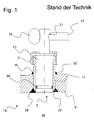
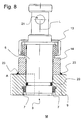
- FIG. 1 shows a partially schematic sectional view of a previously known from the prior art grinding container 1 a with opening 3 and plug 5.
- the grinding container 1 a and 1 is in the FIGS. 1 to 6 present patent application for reasons of clarity only partially shown and formed as a hollow cylinder.
- the grinding container 1 a FIG. 1 as well as the following in the embodiments FIGS. 2 to 6 The grinding container 1 shown are not formed as part of a present in the figures patent application with crushing mill shown.
- Part of the grinding container 1a is a container shell 9, which defines a grinding space M.
- the respective solid to be comminuted and various patent applications in the figures are not arranged with the grinding balls shown.
- the opening 3 penetrates the container casing 9 and provides access to the grinding chamber M, so that via the opening 3 grinding balls can be guided into the grinding chamber M and can be removed from the grinding chamber M.
- the opening 3 of the grinding container 1 a is closed via the plug 5 during the respective comminution process.
- the plug 5 is held in a receptacle 11, which forms a thread at its free and in the direction away from the container jacket 9 facing end.
- the plug 5 also has a contact means 13 with mating thread, which is in engagement with the thread of the receptacle 11 for holding the plug 5.
- a fixation 15 via which the receptacle 11 is fixed to the container casing 9.
- a bolt 17 engages through an opening 21 of the plug 5.
- the bolt 17 is at its free end with a ball 19 in conjunction, so that the position of the plug 5 is fixed in the opening 3 ,
- a weld 22 can be seen, by means of which the receptacle 11 is fixed to the container casing 9.
- the plug 5 is associated with an O-ring 20.
- the O-ring is to prevent settling of grinding balls and solid particles between the pin 5 and the receptacle 11.
- FIG. 2 shows a partially schematic sectional view of an embodiment of a grinding container 1 according to the invention with opening 3 and plug 5.
- the grinding container 1 is also formed as part of a crushing mill.
- the grinding container is 1 in FIG. 2 also not completely shown but only a portion of the grinding container 1.
- the grinding container 1 has a container shell 9, which defines a grinding chamber M.
- the solid to be comminuted is taken up together with the respective grinding elements or grinding balls.
- FIG. 1 has the grinding container 1 off FIG. 2 an opening 3 for feeding and discharging the respective grinding elements in and out of the grinding chamber M.
- a plug 5 can be seen, which closes the opening 3.
- the plug 5 is removable, so that the opening 3 is released with removed plug 5 for the purpose of feeding and / or discharge of grinding elements in and / or out of the grinding chamber M.
- a sealing unit 7 can be seen, which prevents settling of solid particles and of grinding balls between the plug 5 and the container casing 9.
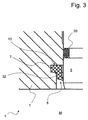
- the sealing unit 7 extends radially around the plug 5 and is received in a form-fitting manner in a groove 10 of the container casing 9. It is conceivable that the sealing unit 7 is inserted by means of a press fit into the groove 10 of the container casing 9. How very good in FIG. 3 to recognize which the cutout A from FIG. 2 shows in detail, the sealing unit 7 has at least partially angled relative to a longitudinal axis L of the plug 5 and inclined in the direction of the grinding chamber M sealing portion 8 which is subjected to force and elastically deformable with an outer circumferential surface of the plug 5 brought into surface contact. Likewise, the sealing portion 8 extends radially about the longitudinal axis L of the plug 5 and is disposed outside the groove 10.
- FIG. 2 also shows an O-ring, which is associated with the stopper 5 and together with the stopper 5 upon release of the opening 3 with reference numeral 20 out of the opening 3 is guided.
- a counter contact means 14 On the side facing away from the grinding chamber M side of the container jacket surface 9 is seated on a counter contact means 14, which forms an external thread.
- the mating contact means 14 is fixed to the container jacket surface 9 via a welded connection 23, arranged completely outside the grinding chamber M and does not enter into the opening 3 or into the container jacket surface 9.
- the plug 5 has a contact means 13, which rotatably with the plug 5 is in communication and forms another thread. For holding the plug 5 in the opening 3, the further thread of the contact means 13 and the thread of the mating contact means 14 are brought into contact with each other. If the plug 5 is to be withdrawn from the opening 3, the plug 5 is rotated together with the contact means 13, wherein the two threads are disengaged. Subsequently, the plug 5 can be withdrawn in the longitudinal direction of the opening 3.
- FIG. 2 it can be seen that the counter-contact means 14 provides a forced guidance for the plug 5, so that the plug 5 can be defined and inserted into the opening 3 in the direction of its longitudinal extent.
- the mating contact means 14 also forms a widening in the direction away from the container jacket surface 9 or funnel-shaped entrance 30, which allows easy positioning of the plug 5 in the mating contact means 14 or in the forced operation.
- FIG. 3 it can be seen that the cross-sectional area of the sealing unit 7 or of the sealing section 8 decreases in a planar manner when approaching the stopper 5. Further, between the sealing unit 7 and the plug 5, a distance 32 is formed, which extends radially about the longitudinal axis L of the plug 5. Meet Mahlemia and / or solids on the grinding chamber M facing side surface of the sealing portion 8, the sealing portion is reversibly elastically deformed and resulting kraftbeaufschlagt with the stopper 5 and 5 brought with an outer surface of the plug 5 in abutment.
- the sealing via the sealing unit 7 is improved due to the kraftbeaufschlagten system, so that a settling of solids and / or grinding balls between the plug 5 and the container jacket surface 9 can be at least largely avoided.
- the distance 32 which is formed between the sealing unit 7 and the stopper 5, allows a greater elastic deformability of the sealing portion 8 and an enlarged force-applied contact of the sealing portion 8 at the Outer shell surface of the plug 5 with resulting improved sealing against the passage of solids and / or grinding elements.
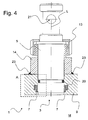
- FIG. 4 shows a partially schematic sectional view of another embodiment of a grinding container 1 according to the invention with opening 3 and plug 5.
- the grinding container 1 according to FIG. 4 via a mating contact means 14 and the plug 5 via a contact means 13, wherein mating contact means 14 and contact means 13 are connected to each other via corresponding threads.
- the counter contact means 14 is further fixed via a welded joint 23 on the side facing away from the grinding chamber M of the container jacket surface 9.
- the plug 5 is associated with an O-ring 20.
- a sealing unit 7 which forms a sealing section 8 which is angled relative to the longitudinal axis L of the plug 5 and inclined in the direction of the grinding chamber M.
- the sealing portion 8 and the entire sealing unit 7 are as a section A of FIG. 4 detailed in FIG. 5 shown.
- a distance 32 is further formed to increase the deformability of the sealing portion 8 and to prevent the passage of solids and grinding balls by virtue of the resulting force-bearing contact of the sealing portion 8 on the outer circumferential surface of the plug 5.
- a further distance 34 between the sealing unit 7 and the container jacket surface 9 is formed.
- the sealing unit 7 is received in a form-fitting manner in the groove 10 of the container jacket surface 9.
- the distance 34 is formed in the region of the groove 10 and extends radially about the longitudinal axis L of the plug 5.
- the sealing unit 7 or the sealing portion 8 is still kraftbeaufschlagt in contact with the outer surface of the plug 5.
- the sealing unit 7 can escape into the opening 34, so that the plug 5 can easily be guided out of the opening 3 in the axial direction.
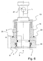
- FIG. 6 shows a partially schematic sectional view of another embodiment of a grinding container 1 according to the invention with opening 3 and plug. 5
- the grinding container 1 from the embodiment of FIG. 6 includes a mating contact means 14 with a thread.
- the plug 5 or the contact means 13 is brought into contact with a thread, which is in engagement with the thread of the mating contact means 14.
- a welded connection 23 is in FIG. 6 to recognize, by means of which the mating contact means 14 is fixed immovably on the container jacket surface 9.
- an O-ring 20 is used, which is in surface contact with the container jacket surface 9.
- a sealing unit 7 is provided, which forms an angle with respect to the longitudinal axis L of the plug 5 employed and inclined in the direction of the grinding chamber M sealing portion 8.
- the sealing portion 8 and the entire sealing unit 7 are as a section A of FIG. 6 detailed in FIG. 7 shown.
- FIG. 7 a sealing portion 8, whose cross-section decreases when approaching the stopper 5 surface. Between sealing unit 7 and outer circumferential surface of the plug 5, a distance 32 is formed. Evident is further a distance 34, which is formed between the sealing unit 7 and the container jacket surface 9 of the grinding container 1. In contrast to the embodiment of the FIGS. 4 and 5 is the distance 34 in the embodiment of FIGS. 6 and 7 completely outside the groove 10 is arranged.
- the sealing portion 8 or a head of the sealing portion 8 is also employed at an angle to the container jacket surface 9.
- the sealing unit 7 is positively received in the groove 10.
- FIG. 8 shows a partially schematic sectional view of another embodiment of a grinding container 1 according to the invention with opening 3 and plug. 5
- a counter contact means 14 which forms a thread and a contact means 13 with a corresponding mating thread. Thread and mating thread engage each other to set the plug 5 in the opening 3.
- the mating contact means 14 is fixed to the container jacket surface 9 with the welded connection shown by reference numeral 23.
- An O-ring 20 is received in a groove of the plug 5.
- Reference numeral 7 refers to a sealing unit which forms an angle with respect to the longitudinal axis L of the plug 5 employed and inclined in the direction of the grinding chamber M sealing portion 8.
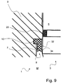
- the sealing portion 8 and the entire sealing unit 7 are as a section A of FIG. 8 detailed in FIG. 9 shown.
- the sealing portion 8 has a V-shaped and in the direction of the grinding chamber M widening shape.
- the sealing portion 28 is compared to the outer circumferential surface of the plug 5 and against the container jacket surface 9 made angled.
- the sealing portion 8 is brought into contact with the container shell surface 9 and with the outer circumferential surface of the plug 5 in contact with contact with grinding elements and / or solid fractions due to the angular orientation of the sealing portion 8 kraftbeaufschlagt. A passage of solids and grinding balls can be at least largely avoided.
- a spacing 32 or 34 is formed in each case in order to increase the elastic deformability of the sealing unit 7.
- the distance 34 is formed entirely outside the groove 10 of the container lateral surface. In the groove 10, the sealing unit 7 is received positively.
Landscapes
- Engineering & Computer Science (AREA)
- Food Science & Technology (AREA)
- Closures For Containers (AREA)
- Crushing And Grinding (AREA)
Description
- Die vorliegende Erfindung betrifft einen Mahlbehälter für eine Zerkleinerungsmühle mit wenigstens einem Stopfen zum Verschließen einer Öffnung.
- Zerkleinerungsmühlen für Feststoffe umfassen in der Regel einen Mahlbehälter, welcher einen Mahlraum definiert. Der Mahlbehälter kann bei aus dem Stand der Technik bekannten Zerkleinerungsmühlen in Rotation versetzt werden oder bei weiteren bekannten Zerkleinerungsmühlen ortsfest gelagert sein.
- Im Mahlraum können sich zum Zwecke des jeweiligen Zerkleinerungsprozesses Mahlkugeln befinden, die beispielsweise über eine Rotation des Mahlraums oder ein im Mahlraum installiertes Rührwerk für die Zerkleinerung des Feststoffes bewegt werden. Um die jeweiligen Mahlkugeln in den Mahlraum einbringen und aus dem Mahlraum abführen zu können, besitzt der jeweilige Mahlbehälter eine verschließbare Öffnung.
- Während eines Zerkleinerungsprozesses sollen die Mahlkugeln nicht aus dem jeweiligen Mahlraum beziehungsweise aus dem jeweiligen Mahlbehälter entweichen. Hierzu ist die Öffnung über einen Stopfen verschlossen, wie z.B. in
DE-19830960-A1 gezeigt. - Da der Feststoff während des Zerkleinerungsprozesses sehr geringe Korngrößen einnehmen kann und zudem Mahlkugeln bekannt sind, die sich durch einen kleinen Durchmesser auszeichnen, steht der jeweilige Stopfen häufig mit Dichtungselementen in Verbindung, um ein Festsetzen von Mahlkugeln beziehungsweise von Feststoffanteilen zwischen dem Stopfen und dem Behältermantel vorzubeugen. Auch soll mit derartigen Dichtungselementen einem Festsetzen von Mahlkugeln mit Verschleißerscheinungen und von beschädigten Mahlkugeln vorgebeugt werden. Über bekannte Dichtungselemente ist der jeweilige Stopfen formschlüssig aufgenommen.
- In der Praxis hat sich gezeigt, dass die formschlüssige Verbindung zwischen dem jeweiligen Dichtungselement und dem Stopfen nicht vollständig ausreicht, um einen ungewollten Kontakt von Feststoffanteilen oder Mahlkugeln mit der Außenmantelfläche des Stopfens ausschließen zu können. Sofern es zu einem Festsetzen von Mahlkörpern und/oder Feststoffanteilen am Stopfen kommt, kann gegebenenfalls der Stopfen in der Öffnung klemmen und nicht mehr aus der Öffnung entfernt werden.
- Aufgabe der Erfindung ist daher einen Mahlbehälter zur Verfügung zu stellen, welcher eine verbesserte Abdichtung für den Stopfen aufweist.
- Die obige Aufgabe wird durch einen Mahlbehälter gelöst, der die Merkmale in dem Patentanspruch 1 umfasst. Weitere vorteilhafte Ausgestaltungen werden durch die Unteransprüche beschrieben.
- Der erfindungsgemäße Mahlbehälter ist vorgesehen für eine Zerkleinerungsmühle und kann somit als Bestandteil einer Kugelmühle beziehungsweise einer Rührwerkskugelmühle ausgebildet sein. Beispielsweise kann der Mahlbehälter eine zylindrische Formgebung besitzen.
- Weiter umfasst der Mahlbehälter einen Behältermantel, der einen Mahlraum definiert, wenigstens eine den Behältermantel durchdringende Öffnung, die einen Zugang zum Mahlraum bereitstellt und wenigstens einen abnehmbar am Mahlbehälter gehaltenen und die Öffnung verschließenden Stopfen. Über die Öffnung beziehungsweise über den Zugang können Mahlelemente, wie Mahlkugeln oder dergleichen, in den Mahlbehälter beziehungsweise in den Mahlraum eingebracht und aus dem Mahlbehälter beziehungsweise aus dem Mahlraum entnommen werden.
- Bei laufendem Betrieb der Zerkleinerungsmühle ist die Öffnung verschlossen, um einen Austritt von Feststoffen und/oder Mahlelementen aus dem Mahlraum zu verhindern.
- Weiter ist dem Behältermantel und dem Stopfen wenigstens eine elastisch verformbare Dichtungseinheit zwischengeordnet, um ein Festsetzen von Feststoffanteilen und/oder Mahlelementen zwischen dem Stopfen und dem Behältermantel zu unterbinden. Die Dichtungseinheit kann sowohl mit dem Stopfen als auch mit dem Behältermantel in Oberflächenkontakt gebracht sein.
- Erfindungsgemäß ist vorgesehen, dass die Dichtungseinheit zumindest bereichsweise einen winklig gegenüber einer Außenmantelfläche des Stopfens beziehungsweise winklig gegenüber einer Längsachse des Stopfens angestellten und in Richtung des Mahlraums geneigten Dichtungsabschnitt ausbildet, der kraftbeaufschlagt und mit einer Außenmantelfläche des Stopfens in Oberflächenkontakt gebracht ist. Der Dichtungsabschnitt ist als Bestandteil der Dichtungseinheit sinnvollerweise ebenso elastisch verformbar.
- Weiter kann eine dem Mahlraum zugewandte Seitenfläche der Dichtungseinheit beziehungsweise des Dichtungsabschnittes gegenüber der Längsachse des Stopfens und/oder der Außenmantelfläche des Stopfens winklig angestellt sein. Vorteilhafterweise wird aufgrund der winkligen Anstellung und bei Kontakt von Feststoffanteilen und/oder Mahlelementen mit dem Dichtungsabschnitt seine kraftbeaufschlagte Anlage an der Außenmantelfläche des Stopfens erhöht. Durch die kraftbeaufschlagte Anlage können Feststoffanteile und/oder Mahlelemente die Dichtungseinheit nicht oder erschwert passieren, womit einem Festsetzen von Feststoffanteilen und/oder Mahlelementen zwischen dem Stopfen und dem Behältermantel entgegengewirkt werden kann.
- In besonders bevorzugten Ausführungsformen kann die Dichtungseinheit form- und/oder kraftschlüssig durch den Behältermantel gehalten werden. Der Behältermantel kann hierzu eine Aussparung beziehungsweise eine Nut ausbilden, in welche die Dichtungseinheit formschlüssig eingesetzt ist. Wird der Stopfen vom Mahlbehälter abgenommen beziehungsweise aus der Öffnung entfernt, so kann die Dichtungseinheit aufgrund ihrer form- und/oder kraftschlüssigen Verbindung weiterhin vom Behältermantel gehalten werden. Die Aussparung beziehungsweise die Nut kann radial um die Längsachse des Stopfens in den Behältermantel eingebracht sein. Wird der Stopfen erneut in die Öffnung eingesetzt, so kann hierbei der Stopfen kraftbeaufschlagt mit der Dichtungseinheit beziehungsweise mit dem Dichtungsabschnitt in Anlage gebracht werden. Eine dichtende Verbindung zwischen dem Stopfen und dem Behältermantel ist somit hergestellt.
- Weiter ist vorstellbar, dass zwischen der Dichtungseinheit und dem Stopfen wenigstens ein Abstand ausgebildet ist, der sich radial um die Längsachse des Stopfens erstreckt. Hierdurch kann der Dichtungsabschnitt bei Kontakt mit Feststoffen und/oder Mahlelementen stärker elastisch verformt werden, wodurch seine kraftbeaufschlagte Anlage am Stopfen vergrößert wird. Der Abstand kann sich direkt an den winklig gegenüber der Außenmantelfläche des Stopfens angestellten Dichtungsabschnitt anschließen.
- Auch kann es sein, dass zwischen der Dichtungseinheit und dem Behältermantel ein Abstand ausgebildet ist, der sich radial um die Längsachse des Stopfens erstreckt. Da der Dichtungsabschnitt kraftbeaufschlagt mit dem Stopfen in Oberflächenkontakt steht, kann sich die Dichtungseinheit bei einer Entnahme des Stopfens reversibel elastisch verformen und hierbei in den Abstand zurückweichen. Mit bevorzugter Ausführungsform, bei welcher zwischen der Dichtungseinheit und dem Behältermantel ein Abstand ausgebildet ist, kann somit eine einfachere Entnahme des Stopfens aus der Öffnung erfolgen.
- Weiter kann der Dichtungsabschnitt eine V-förmige und sich in Richtung des Mahlraumes verbreiternde Formgebung besitzen. Hierbei kann der Dichtungsabschnitt mit der Behältermantelfläche und der Außenmantelfläche des Stopfens kraftbeaufschlagt in Oberflächenkontakt gebracht sein. Sofern Feststoffe und/oder Mahlelemente gegen den Dichtungsabschnitt bewegt werden, wird die kraftbeaufschlagte Anlage der Dichtungseinheit an dem Stopfen und an der Behältermantelfläche erhöht. In der Praxis können Ausführungsformen, bei welchen der Dichtungsabschnitt eine V-förmige Formgebung besitzt, verwendet werden, um eine verbesserte Abdichtung zwischen dem Dichtungselement und der Behältermantelfläche bereit zu stellen.
- Weiter kann der Stopfen entlang seines Außenumfangs eine Nut ausbilden, in welcher ein O-Ring aufgenommen ist. Der O-Ring kann an der Behältermantelfläche anliegen, so dass via den O-Ring und seine Anlage an der Behältermantelfläche eine weitere Dichtung ausgebildet ist, welche einen Durchtritt von Mahlelementen und/oder von Feststoffanteilen verhindert. Durch die Aufnahme des O-Rings in der Nut des Stopfens kann der O-Ring gegebenenfalls zusammen mit dem Stopfen von der Öffnung abgezogen werden.
- Auch kann vorgesehen sein, dass der Stopfen ein oder mehrere Kontaktmittel ausbildet. Dem Mahlbehälter können im Bereich der Öffnung ein oder mehrere korrespondierende Gegenkontaktmittel zugeordnet sein, wobei die ein oder mehreren Kontaktmittel und die ein oder mehreren Gegenkontaktmittel zum Halten des Stopfens lösbar miteinander in Verbindung gebracht sind. Beispielsweise können die ein oder mehreren Kontaktmittel ein Gewinde umfassen und die ein oder mehreren Gegenkontaktmittel ein Gegengewinde, das mit dem Gewinde zum Halten des Stopfens in Verbindung gebracht ist. Für den angesprochenen Fachmann ist klar, dass auch weitere Mechanismen, wie beispielsweise Rast- und/oder Schnapp- und/oder Klemmverbindungen geeignet sind, um die entsprechenden Kontaktmittel und Gegenkontaktmittel miteinander zu verbinden.
- Auch können die Gegenkontaktmittel über wenigstens eine Schweißverbindung am Behältermantel festgesetzt sein. Die Gegenkontaktmittel sind bevorzugt vollständig außerhalb des via die Behältermantelfläche gebildeten Mahlraums angeordnet und ortsfest am Behältermantel gehalten.
- Zudem kann der Stopfen einen Durchbruch aufweisen, durch den ein Bolzen zum Halten des Stopfens bei verschlossener Öffnung greift. Sofern der Stopfen über die vorherig beschriebenen Kontaktmittel und Gegenkontaktmittel in der Öffnung gehalten ist, kann der Bolzen eine redundante Sicherung des Stopfens gegen ungewollte Entnahme aus der Öffnung bereitstellen.
- Im Folgenden sollen Ausführungsbeispiele die Erfindung und ihre Vorteile anhand der beigefügten Figuren näher erläutern. Die Größenverhältnisse der einzelnen Elemente zueinander in den Figuren entsprechen nicht immer den realen Größenverhältnissen, da einige Formen vereinfacht und andere Formen zur besseren Veranschaulichung vergrößert im Verhältnis zu anderen Elementen dargestellt sind.
-
Figur 1 zeigt eine teilweise schematische Schnittdarstellung eines bereits aus dem Stand der Technik bekannten Mahlbehälters mit Öffnung und Stopfen; -
Figur 2 zeigt eine teilweise schematische Schnittdarstellung einer Ausführungsform eines erfindungsgemäßen Mahlbehälters mit Öffnung und Stopfen; -
Figur 3 zeigt den Ausschnitt A ausFigur 2 in vergrößerter Darstellung; -
Figur 4 zeigt eine teilweise schematische Schnittdarstellung einer weiteren Ausführungsform eines erfindungsgemäßen Mahlbehälters mit Öffnung und Stopfen; -
Figur 5 zeigt den Ausschnitt A ausFigur 4 in vergrößerter Darstellung; -
Figur 6 zeigt eine teilweise schematische Schnittdarstellung einer weiteren Ausführungsform eines erfindungsgemäßen Mahlbehälters mit Öffnung und Stopfen; -
Figur 7 zeigt den Ausschnitt A ausFigur 6 in vergrößerter Darstellung; -
Figur 8 zeigt eine teilweise schematische Schnittdarstellung einer weiteren Ausführungsform eines erfindungsgemäßen Mahlbehälters mit Öffnung und Stopfen; -
Figur 9 zeigt den Ausschnitt A ausFigur 8 in vergrößerter Darstellung. - Für gleiche oder gleich wirkende Elemente der Erfindung werden identische Bezugszeichen verwendet. Ferner werden der Übersicht halber nur Bezugszeichen in den einzelnen Figuren dargestellt, die für die Beschreibung der jeweiligen Figur erforderlich sind. Die dargestellten Ausführungsformen stellen lediglich Beispiele dar, wie der erfindungsgemäße Mahlbehälter ausgestaltet sein kann und stellen keine abschließende Begrenzung dar.
-
Figur 1 zeigt eine teilweise schematische Schnittdarstellung eines bereits aus dem Stand der Technik bekannten Mahlbehälters 1 a mit Öffnung 3 und Stopfen 5. Der Mahlbehälter 1 a beziehungsweise 1 ist in denFiguren 1 bis 6 vorliegender Patentanmeldung aus Gründen der Übersichtlichkeit lediglich teilweise dargestellt und als Hohlzylinder ausgebildet. - Der Mahlbehälter 1 a aus
Figur 1 sowie ebenso die in den Ausführungsbeispielen nachfolgenderFiguren 2 bis 6 dargestellten Mahlbehälter 1 sind als Bestandteil einer in den Figuren vorliegender Patentanmeldung nicht mit dargestellten Zerkleinerungsmühle ausgebildet. - Bestandteil des Mahlbehälters 1a ist ein Behältermantel 9, der einen Mahlraum M definiert. Im Mahlraum M sind der jeweilige zu zerkleinernde Feststoff sowie diverse in den Figuren vorliegender Patentanmeldung nicht mit dargestellte Mahlkugeln angeordnet. Die Öffnung 3 durchdringt den Behältermantel 9 und stellt einen Zugang zum Mahlraum M bereit, so dass via die Öffnung 3 Mahlkugeln in den Mahlraum M geführt werden können und aus dem Mahlraum M entnehmbar sind.
- Um einen Austritt von Mahlkugeln und/oder Feststoffanteilen aus dem Mahlraum M während eines Zerkleinerungsprozesses zu verhindern, ist die Öffnung 3 des Mahlbehälters 1 a während des jeweiligen Zerkleinerungsprozesses über den Stopfen 5 verschlossen. Hierbei ist der Stopfen 5 in einer Aufnahme 11 gehalten, die an ihrem freien und in Richtung weg von dem Behältermantel 9 weisenden Ende ein Gewinde ausbildet. Der Stopfen 5 besitzt zudem ein Kontaktmittel 13 mit Gegengewinde, welches mit dem Gewinde der Aufnahme 11 zum Halten des Stopfens 5 in Eingriff steht.
- Es ist weiter eine Fixierung 15 zu erkennen, über welche die Aufnahme 11 am Behältermantel 9 festgesetzt ist. Um eine redundante Sicherung für den Stopfen 5 bereitzustellen, greift ein Bolzen 17 durch einen Durchbruch 21 des Stopfens 5. Der Bolzen 17 steht an seinem freien Ende mit einer Kugel 19 in Verbindung, so dass die Position des Stopfens 5 in der Öffnung 3 festgesetzt ist.
- Weiter ist eine Schweißnaht 22 zu erkennen, mittels welcher die Aufnahme 11 am Behältermantel 9 fixiert wird. Dem Stopfen 5 ist ein O-Ring 20 zugeordnet. Der O-Ring soll ein Festsetzen von Mahlkugeln und Feststoffanteilen zwischen dem Bolzen 5 und der Aufnahme 11 unterbinden.
- Mittels des O-Rings 20 kann nicht mit Gewissheit ausgeschlossen werden, dass sich Mahlkugeln oder Feststoffanteile zwischen dem Stopfen 5 und der Aufnahme 11 festsetzen.
-
Figur 2 zeigt eine teilweise schematische Schnittdarstellung einer Ausführungsform eines erfindungsgemäßen Mahlbehälters 1 mit Öffnung 3 und Stopfen 5. Der Mahlbehälter 1 ist ebenso als Bestandteil einer Zerkleinerungsmühle ausgebildet. - Aus Gründen der Übersichtlichkeit ist der Mahlbehälter 1 in
Figur 2 ebenso nicht vollständig dargestellt sondern lediglich ein Teilbereich des Mahlbehälters 1. Der Mahlbehälter 1 besitzt einen Behältermantel 9, der einen Mahlraum M definiert. Im Mahlraum M ist der zu zerkleinernde Feststoff zusammen mit den jeweiligen Mahlelementen bzw. Mahlkugeln aufgenommen. - Ebenso wie der Mahlbehälter 1 a aus
Figur 1 besitzt der Mahlbehälter 1 ausFigur 2 eine Öffnung 3 zum Zu- und Abführen der jeweiligen Mahlelemente in und aus dem Mahlraum M. Weiter ist ein Stopfen 5 zu erkennen, der die Öffnung 3 verschließt. Der Stopfen 5 ist abnehmbar, so dass die Öffnung 3 bei abgenommenem Stopfen 5 zum Zwecke einer Zu- und/oder Abführung von Mahlelementen in und/oder aus dem Mahlraum M freigegeben ist. Zu erkennen ist weiter eine Durchbruch 21, ausgebildet im Stopfen 5 und vorgesehen zur Sicherung des Stopfens 5 gegen Deorientierung mittels eines inFigur 2 nicht dargestellten Bolzens. - Weiterhin ist eine Dichtungseinheit 7 zu erkennen, welche ein Festsetzen von Feststoffanteilen und von Mahlkugeln zwischen dem Stopfen 5 und dem Behältermantel 9 verhindert. Die Dichtungseinheit 7 erstreckt sich radial um den Stopfen 5 und ist in einer Nut 10 des Behältermantels 9 formschlüssig aufgenommen. Vorstellbar ist, dass die Dichtungseinheit 7 mittels Presspassung in die Nut 10 des Behältermantels 9 eingesetzt ist. Wie sehr gut in
Figur 3 zu erkennen, welche den Ausschnitt A ausFigur 2 detailliert zeigt, besitzt die Dichtungseinheit 7 zumindest bereichsweise einen winklig gegenüber einer Längsachse L des Stopfens 5 angestellten und in Richtung des Mahlraums M geneigten Dichtungsabschnitt 8, der kraftbeaufschlagt und elastisch verformbar mit einer Außenmantelfläche des Stopfens 5 in Oberflächenkontakt gebracht ist. Ebenso erstreckt sich der Dichtungsabschnitt 8 radial um die Längsachse L des Stopfens 5 und ist außerhalb der Nut 10 angeordnet. -
Figur 2 zeigt unter Verweis mit Bezugsziffer 20 zudem einen O-Ring, welcher dem Stopfen 5 zugeordnet ist und zusammen mit dem Stopfen 5 bei Freigabe der Öffnung 3 aus der Öffnung 3 geführt wird. Auf der dem Mahlraum M abgewandten Seite der Behältermantelfläche 9 sitzt ein Gegenkontaktmittel 14 auf, welches ein Außengewinde ausbildet. Das Gegenkontaktmittel 14 ist über eine Schweißverbindung 23 an der Behältermantelfläche 9 fixiert, vollständig außerhalb des Mahlraums M angeordnet und tritt in die Öffnung 3 beziehungsweise in die Behältermantelfläche 9 nicht ein. - Der Stopfen 5 verfügt über ein Kontaktmittel 13, welches drehfest mit dem Stopfen 5 in Verbindung steht und ein weiteres Gewinde ausbildet. Zum Halten des Stopfens 5 in der Öffnung 3 sind das weitere Gewinde des Kontaktmittels 13 und das Gewinde des Gegenkontaktmittels 14 miteinander in Verbindung gebracht. Sofern der Stopfen 5 aus der Öffnung 3 abgezogen werden soll, wird der Stopfen 5 zusammen mit dem Kontaktmittel 13 rotierend bewegt, wobei die beiden Gewinde außer Eingriff gebracht werden. Anschließend kann der Stopfen 5 in Längsrichtung von der Öffnung 3 abgezogen werden.
-
Figur 2 lässt darüber hinaus erkennen, dass das Gegenkontaktmittel 14 eine Zwangsführung für den Stopfen 5 bereitstellt, so dass der Stopfen 5 definiert und in Richtung seiner Längserstreckung in die Öffnung 3 eingesetzt werden kann. Das Gegenkontaktmittel 14 bildet zudem einen sich in Richtung weg von der Behältermantelfläche 9 verbreiternden beziehungsweise trichterförmigen Eingang 30 aus, welcher eine einfache Positionierung des Stopfens 5 im Gegenkontaktmittel 14 beziehungsweise in der Zwangsführung erlaubt. -
Figur 3 lässt zudem erkennen, dass sich die Querschnittsfläche der Dichtungseinheit 7 beziehungsweise des Dichtungsabschnittes 8 bei Annäherung an den Stopfen 5 flächig vermindert. Weiter ist zwischen der Dichtungseinheit 7 und dem Stopfen 5 ein Abstand 32 ausgebildet, der sich radial um die Längsachse L des Stopfens 5 erstreckt. Treffen Mahlelemente und/oder Feststoffanteile auf die dem Mahlraum M zugewandte Seitenfläche des Dichtungsabschnittes 8, so wird der Dichtungsabschnitt reversibel elastisch verformt und hieraus resultierend kraftbeaufschlagt mit dem Stopfen 5 beziehungsweise mit einer Außenmantelfläche des Stopfens 5 in Anlage gebracht. Die Abdichtung via die Dichtungseinheit 7 wird aufgrund der kraftbeaufschlagten Anlage verbessert, so dass ein Festsetzen von Feststoffanteilen und/oder Mahlkugeln zwischen dem Stopfen 5 und der Behältermantelfläche 9 zumindest weitgehend vermieden werden kann. Der Abstand 32, welcher zwischen der Dichtungseinheit 7 und dem Stopfen 5 ausgebildet ist, erlaubt eine größere elastische Verformbarkeit des Dichtungsabschnittes 8 sowie eine vergrößerte kraftbeaufschlagte Anlage des Dichtungsabschnittes 8 an der Außenmantelfläche des Stopfens 5 mit hieraus resultierender verbesserter Abdichtung gegen Durchtritt von Feststoffen und/oder Mahlelementen. -
Figur 4 zeigt eine teilweise schematische Schnittdarstellung einer weiteren Ausführungsform eines erfindungsgemäßen Mahlbehälters 1 mit Öffnung 3 und Stopfen 5. Ebenso wie die Ausführungsform aus den vorhergehendenFiguren 2 und3 verfügt der Mahlbehälter 1 gemäßFigur 4 über ein Gegenkontaktmittel 14 sowie der Stopfen 5 über ein Kontaktmittel 13, wobei Gegenkontaktmittel 14 und Kontaktmittel 13 über korrespondierende Gewinde miteinander in Verbindung stehen. Das Gegenkontaktmittel 14 ist weiterhin über eine Schweißverbindung 23 an der dem Mahlraum M abgewandten Seite der Behältermantelfläche 9 festgesetzt. Dem Stopfen 5 ist ein O-Ring 20 zugeordnet. - Eine Dichtungseinheit 7 ist vorhanden, welche einen winklig gegenüber der Längsachse L des Stopfens 5 angestellten und in Richtung des Mahlraums M geneigten Dichtungsabschnitt 8 ausgebildet. Der Dichtungsabschnitt 8 sowie die gesamte Dichtungseinheit 7 sind als Ausschnitt A der
Figur 4 detailliert inFigur 5 dargestellt. - Zwischen Dichtungseinheit 7 und der Außenmantelfläche des Stopfens 5 ist weiterhin ein Abstand 32 ausgebildet, um die Verformbarkeit des Dichtungsabschnittes 8 zu erhöhen und mittels der hieraus resultierenden kraftbeaufschlagten Anlage des Dichtungsabschnittes 8 an der Außenmantelfläche des Stopfens 5 einen Durchtritt von Feststoffen und Mahlkugeln zu verhindern.
- Zudem ist in dem Ausführungsbeispiel aus den
Figuren 4 und5 ein weiterer Abstand 34 zwischen der Dichtungseinheit 7 und der Behältermantelfläche 9 ausgebildet. Die Dichtungseinheit 7 ist formschlüssig in der Nut 10 der Behältermantelfläche 9 aufgenommen. Der Abstand 34 ist im Bereich der Nut 10 ausgebildet und erstreckt sich radial um die Längsachse L des Stopfens 5. - Sofern der Stopfen 5 längsgerichtet aus der Öffnung 3 des Mahlbehälters 1 abgezogen wird, befindet sich hierbei die Dichtungseinheit 7 beziehungsweise der Dichtungsabschnitt 8 weiterhin kraftbeaufschlagt in Anlage mit der Außenmantelfläche des Stopfens 5. Bei Bewegung des Stopfens 5 entlang seiner Längsrichtung und aus der Öffnung 3 kann die Dichtungseinheit 7 aufgrund ihrer elastischen Verformbarkeit in die Öffnung 34 ausweichen, so dass der Stopfen 5 leicht in axialer Richtung aus der Öffnung 3 geführt werden kann.
-
Figur 6 zeigt eine teilweise schematische Schnittdarstellung einer weiteren Ausführungsform eines erfindungsgemäßen Mahlbehälters 1 mit Öffnung 3 und Stopfen 5. - Auch der Mahlbehälter 1 aus dem Ausführungsbeispiel der
Figur 6 umfasst ein Gegenkontaktmittel 14 mit einem Gewinde. Ebenso ist der Stopfen 5 beziehungsweise das Kontaktmittel 13 mit einem Gewinde in Verbindung gebracht, welches mit dem Gewinde des Gegenkontaktmittels 14 in Eingriff steht. Eine Schweißverbindung 23 ist inFigur 6 zu erkennen, mittels welcher das Gegenkontaktmittel 14 an der Behältermantelfläche 9 unbeweglich festgesetzt ist. In eine Nut des Stopfens 5 ist ein O-Ring 20 eingesetzt, welcher mit der Behältermantelfläche 9 in Oberflächenkontakt steht. - Auch im Ausführungsbeispiel aus
Figur 6 ist eine Dichtungseinheit 7 vorhanden, die einen winklig gegenüber der Längsachse L des Stopfens 5 angestellten und in Richtung des Mahlraums M geneigten Dichtungsabschnitt 8 ausgebildet. Der Dichtungsabschnitt 8 sowie die gesamte Dichtungseinheit 7 sind als Ausschnitt A derFigur 6 detailliert inFigur 7 dargestellt. - So zeigt
Figur 7 einen Dichtungsabschnitt 8, dessen Querschnitt sich bei Annäherung an den Stopfen 5 flächig vermindert. Zwischen Dichtungseinheit 7 und Außenmantelfläche des Stopfens 5 ist ein Abstand 32 ausgebildet. Zu erkennen ist weiterhin ein Abstand 34, welcher zwischen der Dichtungseinheit 7 und der Behältermantelfläche 9 des Mahlbehälters 1 ausgebildet ist. Gegensätzlich zum Ausführungsbeispiel aus denFiguren 4 und5 ist der Abstand 34 im Ausführungsbeispiel derFiguren 6 und7 vollständig außerhalb der Nut 10 angeordnet. Der Dichtungsabschnitt 8 beziehungsweise ein Kopf des Dichtungsabschnittes 8 ist zudem winklig gegen die Behältermantelfläche 9 angestellt. Die Dichtungseinheit 7 ist formschlüssig in der Nut 10 aufgenommen. -
Figur 8 zeigt eine teilweise schematische Schnittdarstellung einer weiteren Ausführungsform eines erfindungsgemäßen Mahlbehälters 1 mit Öffnung 3 und Stopfen 5. - Zu erkennen ist weiterhin ein Gegenkontaktmittel 14, welches ein Gewinde ausbildet sowie ein Kontaktmittel 13 mit einem entsprechenden Gegengewinde. Gewinde und Gegengewinde greifen ineinander um den Stopfen 5 in der Öffnung 3 festzusetzen.
- Das Gegenkontaktmittel 14 ist mit der unter Verweis mit Bezugsziffer 23 dargestellten Schweißverbindung an der Behältermantelfläche 9 festgesetzt. Ein O-Ring 20 ist in einer Nut des Stopfens 5 aufgenommen.
- Bezugsziffer 7 verweist auf eine Dichtungseinheit, die einen winklig gegenüber der Längsachse L des Stopfens 5 angestellten und in Richtung des Mahlraums M geneigten Dichtungsabschnitt 8 ausbildet. Der Dichtungsabschnitt 8 sowie die gesamte Dichtungseinheit 7 sind als Ausschnitt A der
Figur 8 detailliert inFigur 9 dargestellt. - Wie in
Figur 9 zu erkennen, besitzt der Dichtungsabschnitt 8 eine V-förmige und sich in Richtung des Mahlraums M verbreiternde Formgebung. Somit ist der Dichtungsabschnitt 28 gegenüber der Außenmantelfläche des Stopfens 5 und gegenüber der Behältermantelfläche 9 winklig angestellt. Vorteilhafterweise wird der Dichtungsabschnitt 8 bei Kontakt mit Mahlelementen und/oder Feststoffanteilen aufgrund der winkligen Orientierung des Dichtungsabschnittes 8 kraftbeaufschlagt mit der Behältermantelfläche 9 und mit der Außenmantelfläche des Stopfens 5 in Oberflächenkontakt gebracht. Ein Durchtritt von Feststoffanteilen und Mahlkugeln kann hierbei zumindest weitgehend vermieden werden. - Weiter ist zwischen der Dichtungseinheit 7 und der Außenmantelfläche des Stopfens 5 sowie zwischen der Dichtungseinheit 7 und der Behältermantelfläche 9 jeweils ein Abstand 32 beziehungsweise 34 ausgebildet, um die elastische Verformbarkeit der Dichtungseinheit 7 zu erhöhen. Der Abstand 34 ist vollständig außerhalb der Nut 10 der Behältermantelfläche ausgebildet. In der Nut 10 ist die Dichtungseinheit 7 formschlüssig aufgenommen.
- Die Erfindung wurde unter Bezugnahme auf eine bevorzugte Ausführungsform beschrieben. Es ist jedoch für einen Fachmann vorstellbar, dass Abwandlungen oder Änderungen der Erfindung gemacht werden können, ohne dabei den Schutzbereich der nachstehenden Ansprüche zu verlassen.
-
- 1
- Mahlbehälter
- 3
- Öffnung
- 5
- Stopfen
- 7
- Dichtungseinheit
- 8
- Dichtungsabschnitt
- 9
- Behältermantel
- 10
- Nut
- 11
- Aufnahme
- 13
- Kontaktmittel
- 14
- Gegenkontaktmittel
- 15
- Fixierung
- 17
- Bolzen
- 19
- Kugel
- 20
- O-Ring
- 21
- Durchbruch
- 22
- Schweißnaht
- 23
- Schweißverbindung
- 32
- Abstand
- 34
- Abstand
- L
- Längsachse
- M
- Mahlraum
Claims (11)
- Mahlbehälter (1) für eine Zerkleinerungsmühle, umfassend einen Behältermantel (9), der einen Mahlraum (M) definiert, wenigstens eine den Behältermantel (9) durchdringende Öffnung (3), die einen Zugang zum Mahlraum (M) bereitstellt und wenigstens einen abnehmbar am Mahlbehälter (1) gehaltenen und die Öffnung (3) verschließenden Stopfen (5), wobei dem Stopfen (5) und dem Behältermantel (9) wenigstens eine elastisch verformbare Dichtungseinheit (7) zwischengeordnet ist, dadurch gekennzeichnet, dass die Dichtungseinheit (7) zumindest bereichsweise einen winklig gegenüber einer Außenmantelfläche des Stopfens (5) angestellten und in Richtung des Mahlraums (M) geneigten Dichtungsabschnitt (8) ausbildet, der kraftbeaufschlagt der Außenmantelfläche des Stopfens (5) in Oberflächenkontakt gebracht ist.
- Mahlbehälter (1) nach Anspruch 1, bei welchem die Dichtungseinheit (7) form- und/oder kraftschlüssig in einer Nut (10) des Behältermantels (9) gehalten wird.
- Mahlbehälter (1) nach Anspruch 1 oder Anspruch 2, bei welchem zwischen der Dichtungseinheit (7) und dem Stopfen (5) wenigstens ein Abstand (32) ausgebildet ist, der sich radial um die Längsachse (L) des Stopfens (5) erstreckt.
- Mahlbehälter (1) nach einem oder mehreren der Ansprüche 1 bis 3, bei welchem zwischen der Dichtungseinheit (7) und dem Behältermantel (9) wenigstens ein Abstand (34) ausgebildet ist, der sich radial um die Längsachse (L) des Stopfens (5) erstreckt.
- Mahlbehälter (1) nach Anspruch 2 und Anspruch 4, bei welchem wenigstens ein Abstand (34) zwischen der Dichtungseinheit (7) und dem Behältermantel (9) vollständig in und/oder vollständig außerhalb der Nut (10) angeordnet ist.
- Mahlbehälter (1) nach einem oder mehreren der Ansprüche 1 bis 5, bei welchem der Dichtungsabschnitt (8) eine V-förmige und sich in Richtung des Mahlraums (M) verbreiternde Formgebung besitzt.
- Mahlbehälter (1) nach einem oder mehreren der Ansprüche 1 bis 6, bei welchem sich die Querschnittsfläche der Dichtungseinheit (7) bei Annäherung an die Außenmantelfläche des Stopfens (5) flächig vermindert.
- Mahlbehälter (1) nach einem oder mehreren der Ansprüche 1 bis 7, bei welchem der Stopfen (5) entlang seines Außenumfangs eine Nut zur Aufnahme eines O-Rings (20) ausbildet.
- Mahlbehälter (1) nach einem oder mehreren der Ansprüche 1 bis 8, bei welchem der Stopfen (5) ein oder mehrere Kontaktmittel (13) ausbildet und dem Mahlbehälter (1) im Bereich der Öffnung (3) ein oder mehrere korrespondierende Gegenkontaktmittel (14) zugeordnet sind, die zum Halten des Stopfens (5) lösbar miteinander in Verbindung gebracht sind.
- Mahlbehälter (1) nach Anspruch 9, bei welchem die Gegenkontaktmittel über wenigstens eine Schweißverbindung (23) am Behältermantel festgesetzt sind.
- Mahlbehälter (1) nach einem oder mehreren der Ansprüche 1 bis 8, wobei der Stopfen (5) einen Durchbruch (21) aufweist, durch den ein Bolzen zum Halten des Stopfens (3) bei verschlossener Öffnung (3) greift.
Applications Claiming Priority (1)
| Application Number | Priority Date | Filing Date | Title |
|---|---|---|---|
| DE102014101699.8A DE102014101699B3 (de) | 2014-02-12 | 2014-02-12 | Mahlbehälter für Zerkleinerungsmühle mit wenigstens einem Stopfen |
Publications (2)
| Publication Number | Publication Date |
|---|---|
| EP2907578A1 EP2907578A1 (de) | 2015-08-19 |
| EP2907578B1 true EP2907578B1 (de) | 2016-07-06 |
Family
ID=52449918
Family Applications (1)
| Application Number | Title | Priority Date | Filing Date |
|---|---|---|---|
| EP15000154.3A Active EP2907578B1 (de) | 2014-02-12 | 2015-01-21 | Mahlbehälter für Zerkleinerungsmühle mit wenigstens einem Stopfen |
Country Status (3)
| Country | Link |
|---|---|
| EP (1) | EP2907578B1 (de) |
| CN (1) | CN104826705B (de) |
| DE (1) | DE102014101699B3 (de) |
Cited By (1)
| Publication number | Priority date | Publication date | Assignee | Title |
|---|---|---|---|---|
| EP4032615A1 (de) | 2021-01-25 | 2022-07-27 | Wilhelm Niemann GmbH & Co KG | Rührwerksmühle |
Family Cites Families (6)
| Publication number | Priority date | Publication date | Assignee | Title |
|---|---|---|---|---|
| DE1257545B (de) * | 1963-11-27 | 1967-12-28 | Schichau Griep Mischtechnik Ge | Verschliessbares Ablassorgan fuer Behaeltermuehlen |
| CH619759A5 (en) * | 1977-04-13 | 1980-10-15 | Meyer Ag Zuchwil | Shaft seal, in particular on a stirred ball mill or colloid mill |
| DE3837412A1 (de) * | 1988-11-04 | 1990-05-10 | Heinz Welte Ing Gmbh & Co | Separier-vorrichtung zur verhinderung des austritts von mahlkoerpern aus dem arbeitsraum einer maschine zur zerkleinerung, trennung oder vereinigung von stoffen |
| JPH0771643B2 (ja) * | 1988-12-05 | 1995-08-02 | 工業技術院長 | 偏心式円板粉砕機 |
| DE19830960C2 (de) * | 1998-07-10 | 2002-12-12 | Netzsch Erich Holding | Trennvorrichtung für eine Rührwerksmühle |
| CN203209124U (zh) * | 2013-04-16 | 2013-09-25 | 河南富耐克超硬材料股份有限公司 | 具有三维研磨功能的球磨罐及使用该球磨罐的球磨机 |
-
2014
- 2014-02-12 DE DE102014101699.8A patent/DE102014101699B3/de active Active
-
2015
- 2015-01-07 CN CN201510007359.6A patent/CN104826705B/zh active Active
- 2015-01-21 EP EP15000154.3A patent/EP2907578B1/de active Active
Cited By (3)
| Publication number | Priority date | Publication date | Assignee | Title |
|---|---|---|---|---|
| EP4032615A1 (de) | 2021-01-25 | 2022-07-27 | Wilhelm Niemann GmbH & Co KG | Rührwerksmühle |
| DE102021101527A1 (de) | 2021-01-25 | 2022-07-28 | Wilhelm Niemann Gmbh & Co. | Rührwerksmühle |
| DE102021101527B4 (de) | 2021-01-25 | 2023-05-17 | Wilhelm Niemann Gmbh & Co. | Rührwerksmühle |
Also Published As
| Publication number | Publication date |
|---|---|
| DE102014101699B3 (de) | 2015-06-11 |
| CN104826705B (zh) | 2016-06-01 |
| CN104826705A (zh) | 2015-08-12 |
| EP2907578A1 (de) | 2015-08-19 |
Similar Documents
| Publication | Publication Date | Title |
|---|---|---|
| DE102015222640B4 (de) | Kupplungselement und Ventilstößel für eine Kupplung zur Verbindung von Druckmittelleitungen | |
| DE102010018379A1 (de) | Wirbelsäulenimplantat und Werkzeug hierfür | |
| DE202016003401U1 (de) | Druckprüfvorrichtung | |
| EP3079827B1 (de) | Mahlvorrichtung mit verschleissscheibe | |
| DE102007001211B4 (de) | Bremsscheiben-/Nabenverbindung | |
| EP2907578B1 (de) | Mahlbehälter für Zerkleinerungsmühle mit wenigstens einem Stopfen | |
| EP3423224B1 (de) | Elektrisches handkernbohrgerät | |
| DE112020004130T5 (de) | Nippel für schraubkupplung, kupplung und verfahren zum verbinden des nippels | |
| DE202011109867U1 (de) | Kabelverschraubung | |
| DE102016116193A1 (de) | Rotor einer Zerkleinerungsmaschine mit lösbar befestigten Messerhaltern | |
| DE102012008521A1 (de) | Ölwannenanordnung | |
| DE102006026198A1 (de) | Schlauchkupplung mit Sicherung | |
| DE102009043024A1 (de) | Vorrichtung zum Verbinden zweier Rohrenden mit einem formschlüssig wirkenden Sicherungselement | |
| EP2218148B1 (de) | Flüssigkeitsdichter steckverbinder | |
| EP4462003A1 (de) | Verbindung für wasserführende bauteile | |
| DE102012112193A1 (de) | Verschlussanordnung für eine Öffnung | |
| DE102009002000B4 (de) | Vorrichtung zum Freigeben einer Öffnung vom Innenraum eines Lenkgetriebes zur Lenkungsumgebung | |
| EP3006063A1 (de) | Verschlussanordnung für ein trägergehäuse eines medizinischen fluidspeicher- und/oder -leitungssystems | |
| DE10007527C2 (de) | Dichtpackung zum Hindurchführen von Leitungen durch eine Wand | |
| EP2639487B1 (de) | Rohrkupplung mit deckel | |
| EP3534025B1 (de) | Lager | |
| WO2016155687A1 (de) | Verschlusssystem für den mahlbehälter einer zerkleinerungseinrichtung und mahlbehälter mit einem derartigen verschlusssystem und zerkleinerungseinrichtung mit einem mahlbehälter | |
| DE102016107880C5 (de) | Schraubverbindung | |
| EP3438014B1 (de) | Behälterverschlusssystem für einen behälter zur verwendung bei gefriertrocknung sowie verfahren zum verschliessen eines behälters für ein gefriertrocknungsverfahren | |
| DE102023206627A1 (de) | Anschlussvorrichtung zum Verbinden einer Fluidleitung mit einem Anschlusskörper |
Legal Events
| Date | Code | Title | Description |
|---|---|---|---|
| PUAI | Public reference made under article 153(3) epc to a published international application that has entered the european phase |
Free format text: ORIGINAL CODE: 0009012 |
|
| AK | Designated contracting states |
Kind code of ref document: A1 Designated state(s): AL AT BE BG CH CY CZ DE DK EE ES FI FR GB GR HR HU IE IS IT LI LT LU LV MC MK MT NL NO PL PT RO RS SE SI SK SM TR |
|
| AX | Request for extension of the european patent |
Extension state: BA ME |
|
| 17P | Request for examination filed |
Effective date: 20160219 |
|
| RBV | Designated contracting states (corrected) |
Designated state(s): AL AT BE BG CH CY CZ DE DK EE ES FI FR GB GR HR HU IE IS IT LI LT LU LV MC MK MT NL NO PL PT RO RS SE SI SK SM TR |
|
| RIC1 | Information provided on ipc code assigned before grant |
Ipc: B02C 17/18 20060101ALI20160314BHEP Ipc: B02C 17/16 20060101AFI20160314BHEP |
|
| GRAP | Despatch of communication of intention to grant a patent |
Free format text: ORIGINAL CODE: EPIDOSNIGR1 |
|
| INTG | Intention to grant announced |
Effective date: 20160426 |
|
| GRAS | Grant fee paid |
Free format text: ORIGINAL CODE: EPIDOSNIGR3 |
|
| GRAA | (expected) grant |
Free format text: ORIGINAL CODE: 0009210 |
|
| AK | Designated contracting states |
Kind code of ref document: B1 Designated state(s): AL AT BE BG CH CY CZ DE DK EE ES FI FR GB GR HR HU IE IS IT LI LT LU LV MC MK MT NL NO PL PT RO RS SE SI SK SM TR |
|
| REG | Reference to a national code |
Ref country code: GB Ref legal event code: FG4D Free format text: NOT ENGLISH |
|
| REG | Reference to a national code |
Ref country code: AT Ref legal event code: REF Ref document number: 810316 Country of ref document: AT Kind code of ref document: T Effective date: 20160715 Ref country code: CH Ref legal event code: EP |
|
| REG | Reference to a national code |
Ref country code: IE Ref legal event code: FG4D Free format text: LANGUAGE OF EP DOCUMENT: GERMAN |
|
| REG | Reference to a national code |
Ref country code: DE Ref legal event code: R096 Ref document number: 502015000071 Country of ref document: DE |
|
| REG | Reference to a national code |
Ref country code: NL Ref legal event code: MP Effective date: 20160706 |
|
| REG | Reference to a national code |
Ref country code: LT Ref legal event code: MG4D |
|
| PG25 | Lapsed in a contracting state [announced via postgrant information from national office to epo] |
Ref country code: IT Free format text: LAPSE BECAUSE OF FAILURE TO SUBMIT A TRANSLATION OF THE DESCRIPTION OR TO PAY THE FEE WITHIN THE PRESCRIBED TIME-LIMIT Effective date: 20160706 Ref country code: RS Free format text: LAPSE BECAUSE OF FAILURE TO SUBMIT A TRANSLATION OF THE DESCRIPTION OR TO PAY THE FEE WITHIN THE PRESCRIBED TIME-LIMIT Effective date: 20160706 Ref country code: LT Free format text: LAPSE BECAUSE OF FAILURE TO SUBMIT A TRANSLATION OF THE DESCRIPTION OR TO PAY THE FEE WITHIN THE PRESCRIBED TIME-LIMIT Effective date: 20160706 Ref country code: FI Free format text: LAPSE BECAUSE OF FAILURE TO SUBMIT A TRANSLATION OF THE DESCRIPTION OR TO PAY THE FEE WITHIN THE PRESCRIBED TIME-LIMIT Effective date: 20160706 Ref country code: NO Free format text: LAPSE BECAUSE OF FAILURE TO SUBMIT A TRANSLATION OF THE DESCRIPTION OR TO PAY THE FEE WITHIN THE PRESCRIBED TIME-LIMIT Effective date: 20161006 Ref country code: HR Free format text: LAPSE BECAUSE OF FAILURE TO SUBMIT A TRANSLATION OF THE DESCRIPTION OR TO PAY THE FEE WITHIN THE PRESCRIBED TIME-LIMIT Effective date: 20160706 Ref country code: NL Free format text: LAPSE BECAUSE OF FAILURE TO SUBMIT A TRANSLATION OF THE DESCRIPTION OR TO PAY THE FEE WITHIN THE PRESCRIBED TIME-LIMIT Effective date: 20160706 Ref country code: IS Free format text: LAPSE BECAUSE OF FAILURE TO SUBMIT A TRANSLATION OF THE DESCRIPTION OR TO PAY THE FEE WITHIN THE PRESCRIBED TIME-LIMIT Effective date: 20161106 |
|
| PG25 | Lapsed in a contracting state [announced via postgrant information from national office to epo] |
Ref country code: GR Free format text: LAPSE BECAUSE OF FAILURE TO SUBMIT A TRANSLATION OF THE DESCRIPTION OR TO PAY THE FEE WITHIN THE PRESCRIBED TIME-LIMIT Effective date: 20161007 Ref country code: LV Free format text: LAPSE BECAUSE OF FAILURE TO SUBMIT A TRANSLATION OF THE DESCRIPTION OR TO PAY THE FEE WITHIN THE PRESCRIBED TIME-LIMIT Effective date: 20160706 Ref country code: SE Free format text: LAPSE BECAUSE OF FAILURE TO SUBMIT A TRANSLATION OF THE DESCRIPTION OR TO PAY THE FEE WITHIN THE PRESCRIBED TIME-LIMIT Effective date: 20160706 Ref country code: PL Free format text: LAPSE BECAUSE OF FAILURE TO SUBMIT A TRANSLATION OF THE DESCRIPTION OR TO PAY THE FEE WITHIN THE PRESCRIBED TIME-LIMIT Effective date: 20160706 Ref country code: PT Free format text: LAPSE BECAUSE OF FAILURE TO SUBMIT A TRANSLATION OF THE DESCRIPTION OR TO PAY THE FEE WITHIN THE PRESCRIBED TIME-LIMIT Effective date: 20161107 Ref country code: ES Free format text: LAPSE BECAUSE OF FAILURE TO SUBMIT A TRANSLATION OF THE DESCRIPTION OR TO PAY THE FEE WITHIN THE PRESCRIBED TIME-LIMIT Effective date: 20160706 |
|
| REG | Reference to a national code |
Ref country code: DE Ref legal event code: R097 Ref document number: 502015000071 Country of ref document: DE |
|
| PG25 | Lapsed in a contracting state [announced via postgrant information from national office to epo] |
Ref country code: RO Free format text: LAPSE BECAUSE OF FAILURE TO SUBMIT A TRANSLATION OF THE DESCRIPTION OR TO PAY THE FEE WITHIN THE PRESCRIBED TIME-LIMIT Effective date: 20160706 Ref country code: EE Free format text: LAPSE BECAUSE OF FAILURE TO SUBMIT A TRANSLATION OF THE DESCRIPTION OR TO PAY THE FEE WITHIN THE PRESCRIBED TIME-LIMIT Effective date: 20160706 |
|
| PLBE | No opposition filed within time limit |
Free format text: ORIGINAL CODE: 0009261 |
|
| STAA | Information on the status of an ep patent application or granted ep patent |
Free format text: STATUS: NO OPPOSITION FILED WITHIN TIME LIMIT |
|
| PG25 | Lapsed in a contracting state [announced via postgrant information from national office to epo] |
Ref country code: SK Free format text: LAPSE BECAUSE OF FAILURE TO SUBMIT A TRANSLATION OF THE DESCRIPTION OR TO PAY THE FEE WITHIN THE PRESCRIBED TIME-LIMIT Effective date: 20160706 Ref country code: CZ Free format text: LAPSE BECAUSE OF FAILURE TO SUBMIT A TRANSLATION OF THE DESCRIPTION OR TO PAY THE FEE WITHIN THE PRESCRIBED TIME-LIMIT Effective date: 20160706 Ref country code: BG Free format text: LAPSE BECAUSE OF FAILURE TO SUBMIT A TRANSLATION OF THE DESCRIPTION OR TO PAY THE FEE WITHIN THE PRESCRIBED TIME-LIMIT Effective date: 20161006 Ref country code: SM Free format text: LAPSE BECAUSE OF FAILURE TO SUBMIT A TRANSLATION OF THE DESCRIPTION OR TO PAY THE FEE WITHIN THE PRESCRIBED TIME-LIMIT Effective date: 20160706 Ref country code: DK Free format text: LAPSE BECAUSE OF FAILURE TO SUBMIT A TRANSLATION OF THE DESCRIPTION OR TO PAY THE FEE WITHIN THE PRESCRIBED TIME-LIMIT Effective date: 20160706 Ref country code: BE Free format text: LAPSE BECAUSE OF NON-PAYMENT OF DUE FEES Effective date: 20170131 |
|
| 26N | No opposition filed |
Effective date: 20170407 |
|
| REG | Reference to a national code |
Ref country code: DE Ref legal event code: R119 Ref document number: 502015000071 Country of ref document: DE |
|
| PG25 | Lapsed in a contracting state [announced via postgrant information from national office to epo] |
Ref country code: SI Free format text: LAPSE BECAUSE OF FAILURE TO SUBMIT A TRANSLATION OF THE DESCRIPTION OR TO PAY THE FEE WITHIN THE PRESCRIBED TIME-LIMIT Effective date: 20160706 |
|
| PG25 | Lapsed in a contracting state [announced via postgrant information from national office to epo] |
Ref country code: MC Free format text: LAPSE BECAUSE OF FAILURE TO SUBMIT A TRANSLATION OF THE DESCRIPTION OR TO PAY THE FEE WITHIN THE PRESCRIBED TIME-LIMIT Effective date: 20160706 |
|
| REG | Reference to a national code |
Ref country code: FR Ref legal event code: ST Effective date: 20170929 |
|
| PG25 | Lapsed in a contracting state [announced via postgrant information from national office to epo] |
Ref country code: FR Free format text: LAPSE BECAUSE OF NON-PAYMENT OF DUE FEES Effective date: 20170131 |
|
| REG | Reference to a national code |
Ref country code: IE Ref legal event code: MM4A |
|
| PG25 | Lapsed in a contracting state [announced via postgrant information from national office to epo] |
Ref country code: DE Free format text: LAPSE BECAUSE OF NON-PAYMENT OF DUE FEES Effective date: 20170801 Ref country code: LU Free format text: LAPSE BECAUSE OF NON-PAYMENT OF DUE FEES Effective date: 20170121 |
|
| REG | Reference to a national code |
Ref country code: BE Ref legal event code: MM Effective date: 20170131 |
|
| PG25 | Lapsed in a contracting state [announced via postgrant information from national office to epo] |
Ref country code: IE Free format text: LAPSE BECAUSE OF NON-PAYMENT OF DUE FEES Effective date: 20170121 |
|
| PG25 | Lapsed in a contracting state [announced via postgrant information from national office to epo] |
Ref country code: MT Free format text: LAPSE BECAUSE OF FAILURE TO SUBMIT A TRANSLATION OF THE DESCRIPTION OR TO PAY THE FEE WITHIN THE PRESCRIBED TIME-LIMIT Effective date: 20160706 |
|
| PG25 | Lapsed in a contracting state [announced via postgrant information from national office to epo] |
Ref country code: AL Free format text: LAPSE BECAUSE OF FAILURE TO SUBMIT A TRANSLATION OF THE DESCRIPTION OR TO PAY THE FEE WITHIN THE PRESCRIBED TIME-LIMIT Effective date: 20160706 |
|
| PG25 | Lapsed in a contracting state [announced via postgrant information from national office to epo] |
Ref country code: HU Free format text: LAPSE BECAUSE OF FAILURE TO SUBMIT A TRANSLATION OF THE DESCRIPTION OR TO PAY THE FEE WITHIN THE PRESCRIBED TIME-LIMIT; INVALID AB INITIO Effective date: 20150121 |
|
| GBPC | Gb: european patent ceased through non-payment of renewal fee |
Effective date: 20190121 |
|
| PG25 | Lapsed in a contracting state [announced via postgrant information from national office to epo] |
Ref country code: CY Free format text: LAPSE BECAUSE OF FAILURE TO SUBMIT A TRANSLATION OF THE DESCRIPTION OR TO PAY THE FEE WITHIN THE PRESCRIBED TIME-LIMIT Effective date: 20160706 |
|
| PG25 | Lapsed in a contracting state [announced via postgrant information from national office to epo] |
Ref country code: MK Free format text: LAPSE BECAUSE OF FAILURE TO SUBMIT A TRANSLATION OF THE DESCRIPTION OR TO PAY THE FEE WITHIN THE PRESCRIBED TIME-LIMIT Effective date: 20160706 |
|
| PG25 | Lapsed in a contracting state [announced via postgrant information from national office to epo] |
Ref country code: GB Free format text: LAPSE BECAUSE OF NON-PAYMENT OF DUE FEES Effective date: 20190121 |
|
| PG25 | Lapsed in a contracting state [announced via postgrant information from national office to epo] |
Ref country code: TR Free format text: LAPSE BECAUSE OF FAILURE TO SUBMIT A TRANSLATION OF THE DESCRIPTION OR TO PAY THE FEE WITHIN THE PRESCRIBED TIME-LIMIT Effective date: 20160706 |
|
| REG | Reference to a national code |
Ref country code: AT Ref legal event code: MM01 Ref document number: 810316 Country of ref document: AT Kind code of ref document: T Effective date: 20200121 |
|
| PG25 | Lapsed in a contracting state [announced via postgrant information from national office to epo] |
Ref country code: AT Free format text: LAPSE BECAUSE OF NON-PAYMENT OF DUE FEES Effective date: 20200121 |
|
| PGFP | Annual fee paid to national office [announced via postgrant information from national office to epo] |
Ref country code: CH Payment date: 20250201 Year of fee payment: 11 |
|
| REG | Reference to a national code |
Ref country code: CH Ref legal event code: U11 Free format text: ST27 STATUS EVENT CODE: U-0-0-U10-U11 (AS PROVIDED BY THE NATIONAL OFFICE) Effective date: 20260201 |