EP2907480A1 - Längenverstellbares Implantat - Google Patents
Längenverstellbares Implantat Download PDFInfo
- Publication number
- EP2907480A1 EP2907480A1 EP14155656.3A EP14155656A EP2907480A1 EP 2907480 A1 EP2907480 A1 EP 2907480A1 EP 14155656 A EP14155656 A EP 14155656A EP 2907480 A1 EP2907480 A1 EP 2907480A1
- Authority
- EP
- European Patent Office
- Prior art keywords
- implant
- engagement
- recesses
- engage
- length
- Prior art date
- Legal status (The legal status is an assumption and is not a legal conclusion. Google has not performed a legal analysis and makes no representation as to the accuracy of the status listed.)
- Granted
Links
Images




Classifications
-
- A—HUMAN NECESSITIES
- A61—MEDICAL OR VETERINARY SCIENCE; HYGIENE
- A61F—FILTERS IMPLANTABLE INTO BLOOD VESSELS; PROSTHESES; DEVICES PROVIDING PATENCY TO, OR PREVENTING COLLAPSING OF, TUBULAR STRUCTURES OF THE BODY, e.g. STENTS; ORTHOPAEDIC, NURSING OR CONTRACEPTIVE DEVICES; FOMENTATION; TREATMENT OR PROTECTION OF EYES OR EARS; BANDAGES, DRESSINGS OR ABSORBENT PADS; FIRST-AID KITS
- A61F2/00—Filters implantable into blood vessels; Prostheses, i.e. artificial substitutes or replacements for parts of the body; Appliances for connecting them with the body; Devices providing patency to, or preventing collapsing of, tubular structures of the body, e.g. stents
- A61F2/02—Prostheses implantable into the body
- A61F2/30—Joints
- A61F2/44—Joints for the spine, e.g. vertebrae, spinal discs
- A61F2/4455—Joints for the spine, e.g. vertebrae, spinal discs for the fusion of spinal bodies, e.g. intervertebral fusion of adjacent spinal bodies, e.g. fusion cages
- A61F2/4465—Joints for the spine, e.g. vertebrae, spinal discs for the fusion of spinal bodies, e.g. intervertebral fusion of adjacent spinal bodies, e.g. fusion cages having a circular or kidney shaped cross-section substantially perpendicular to the axis of the spine
-
- A—HUMAN NECESSITIES
- A61—MEDICAL OR VETERINARY SCIENCE; HYGIENE
- A61B—DIAGNOSIS; SURGERY; IDENTIFICATION
- A61B17/00—Surgical instruments, devices or methods
- A61B17/56—Surgical instruments or methods for treatment of bones or joints; Devices specially adapted therefor
- A61B17/58—Surgical instruments or methods for treatment of bones or joints; Devices specially adapted therefor for osteosynthesis, e.g. bone plates, screws or setting implements
- A61B17/68—Internal fixation devices, including fasteners and spinal fixators, even if a part thereof projects from the skin
- A61B17/80—Cortical plates, i.e. bone plates; Instruments for holding or positioning cortical plates, or for compressing bones attached to cortical plates
- A61B17/8023—Variable length plates adjustable in both directions
-
- A—HUMAN NECESSITIES
- A61—MEDICAL OR VETERINARY SCIENCE; HYGIENE
- A61B—DIAGNOSIS; SURGERY; IDENTIFICATION
- A61B17/00—Surgical instruments, devices or methods
- A61B17/56—Surgical instruments or methods for treatment of bones or joints; Devices specially adapted therefor
- A61B17/58—Surgical instruments or methods for treatment of bones or joints; Devices specially adapted therefor for osteosynthesis, e.g. bone plates, screws or setting implements
- A61B17/68—Internal fixation devices, including fasteners and spinal fixators, even if a part thereof projects from the skin
- A61B17/70—Spinal positioners or stabilisers, e.g. stabilisers comprising fluid filler in an implant
- A61B17/7059—Cortical plates
-
- A—HUMAN NECESSITIES
- A61—MEDICAL OR VETERINARY SCIENCE; HYGIENE
- A61F—FILTERS IMPLANTABLE INTO BLOOD VESSELS; PROSTHESES; DEVICES PROVIDING PATENCY TO, OR PREVENTING COLLAPSING OF, TUBULAR STRUCTURES OF THE BODY, e.g. STENTS; ORTHOPAEDIC, NURSING OR CONTRACEPTIVE DEVICES; FOMENTATION; TREATMENT OR PROTECTION OF EYES OR EARS; BANDAGES, DRESSINGS OR ABSORBENT PADS; FIRST-AID KITS
- A61F2/00—Filters implantable into blood vessels; Prostheses, i.e. artificial substitutes or replacements for parts of the body; Appliances for connecting them with the body; Devices providing patency to, or preventing collapsing of, tubular structures of the body, e.g. stents
- A61F2/02—Prostheses implantable into the body
- A61F2/30—Joints
- A61F2/46—Special tools for implanting artificial joints
- A61F2/4603—Special tools for implanting artificial joints for insertion or extraction of endoprosthetic joints or of accessories thereof
- A61F2/4611—Special tools for implanting artificial joints for insertion or extraction of endoprosthetic joints or of accessories thereof of spinal prostheses
-
- A—HUMAN NECESSITIES
- A61—MEDICAL OR VETERINARY SCIENCE; HYGIENE
- A61F—FILTERS IMPLANTABLE INTO BLOOD VESSELS; PROSTHESES; DEVICES PROVIDING PATENCY TO, OR PREVENTING COLLAPSING OF, TUBULAR STRUCTURES OF THE BODY, e.g. STENTS; ORTHOPAEDIC, NURSING OR CONTRACEPTIVE DEVICES; FOMENTATION; TREATMENT OR PROTECTION OF EYES OR EARS; BANDAGES, DRESSINGS OR ABSORBENT PADS; FIRST-AID KITS
- A61F2/00—Filters implantable into blood vessels; Prostheses, i.e. artificial substitutes or replacements for parts of the body; Appliances for connecting them with the body; Devices providing patency to, or preventing collapsing of, tubular structures of the body, e.g. stents
- A61F2/02—Prostheses implantable into the body
- A61F2/30—Joints
- A61F2002/30001—Additional features of subject-matter classified in A61F2/28, A61F2/30 and subgroups thereof
- A61F2002/30108—Shapes
- A61F2002/3011—Cross-sections or two-dimensional shapes
- A61F2002/30138—Convex polygonal shapes
- A61F2002/30148—Convex polygonal shapes lozenge- or diamond-shaped
-
- A—HUMAN NECESSITIES
- A61—MEDICAL OR VETERINARY SCIENCE; HYGIENE
- A61F—FILTERS IMPLANTABLE INTO BLOOD VESSELS; PROSTHESES; DEVICES PROVIDING PATENCY TO, OR PREVENTING COLLAPSING OF, TUBULAR STRUCTURES OF THE BODY, e.g. STENTS; ORTHOPAEDIC, NURSING OR CONTRACEPTIVE DEVICES; FOMENTATION; TREATMENT OR PROTECTION OF EYES OR EARS; BANDAGES, DRESSINGS OR ABSORBENT PADS; FIRST-AID KITS
- A61F2/00—Filters implantable into blood vessels; Prostheses, i.e. artificial substitutes or replacements for parts of the body; Appliances for connecting them with the body; Devices providing patency to, or preventing collapsing of, tubular structures of the body, e.g. stents
- A61F2/02—Prostheses implantable into the body
- A61F2/30—Joints
- A61F2002/30001—Additional features of subject-matter classified in A61F2/28, A61F2/30 and subgroups thereof
- A61F2002/30108—Shapes
- A61F2002/30199—Three-dimensional shapes
- A61F2002/30224—Three-dimensional shapes cylindrical
- A61F2002/30235—Three-dimensional shapes cylindrical tubular, e.g. sleeves
-
- A—HUMAN NECESSITIES
- A61—MEDICAL OR VETERINARY SCIENCE; HYGIENE
- A61F—FILTERS IMPLANTABLE INTO BLOOD VESSELS; PROSTHESES; DEVICES PROVIDING PATENCY TO, OR PREVENTING COLLAPSING OF, TUBULAR STRUCTURES OF THE BODY, e.g. STENTS; ORTHOPAEDIC, NURSING OR CONTRACEPTIVE DEVICES; FOMENTATION; TREATMENT OR PROTECTION OF EYES OR EARS; BANDAGES, DRESSINGS OR ABSORBENT PADS; FIRST-AID KITS
- A61F2/00—Filters implantable into blood vessels; Prostheses, i.e. artificial substitutes or replacements for parts of the body; Appliances for connecting them with the body; Devices providing patency to, or preventing collapsing of, tubular structures of the body, e.g. stents
- A61F2/02—Prostheses implantable into the body
- A61F2/30—Joints
- A61F2002/30001—Additional features of subject-matter classified in A61F2/28, A61F2/30 and subgroups thereof
- A61F2002/30316—The prosthesis having different structural features at different locations within the same prosthesis; Connections between prosthetic parts; Special structural features of bone or joint prostheses not otherwise provided for
- A61F2002/30329—Connections or couplings between prosthetic parts, e.g. between modular parts; Connecting elements
- A61F2002/30331—Connections or couplings between prosthetic parts, e.g. between modular parts; Connecting elements made by longitudinally pushing a protrusion into a complementarily-shaped recess, e.g. held by friction fit
- A61F2002/30362—Connections or couplings between prosthetic parts, e.g. between modular parts; Connecting elements made by longitudinally pushing a protrusion into a complementarily-shaped recess, e.g. held by friction fit with possibility of relative movement between the protrusion and the recess
- A61F2002/30364—Rotation about the common longitudinal axis
- A61F2002/30367—Rotation about the common longitudinal axis with additional means for preventing said rotation
-
- A—HUMAN NECESSITIES
- A61—MEDICAL OR VETERINARY SCIENCE; HYGIENE
- A61F—FILTERS IMPLANTABLE INTO BLOOD VESSELS; PROSTHESES; DEVICES PROVIDING PATENCY TO, OR PREVENTING COLLAPSING OF, TUBULAR STRUCTURES OF THE BODY, e.g. STENTS; ORTHOPAEDIC, NURSING OR CONTRACEPTIVE DEVICES; FOMENTATION; TREATMENT OR PROTECTION OF EYES OR EARS; BANDAGES, DRESSINGS OR ABSORBENT PADS; FIRST-AID KITS
- A61F2/00—Filters implantable into blood vessels; Prostheses, i.e. artificial substitutes or replacements for parts of the body; Appliances for connecting them with the body; Devices providing patency to, or preventing collapsing of, tubular structures of the body, e.g. stents
- A61F2/02—Prostheses implantable into the body
- A61F2/30—Joints
- A61F2002/30001—Additional features of subject-matter classified in A61F2/28, A61F2/30 and subgroups thereof
- A61F2002/30316—The prosthesis having different structural features at different locations within the same prosthesis; Connections between prosthetic parts; Special structural features of bone or joint prostheses not otherwise provided for
- A61F2002/30329—Connections or couplings between prosthetic parts, e.g. between modular parts; Connecting elements
- A61F2002/30331—Connections or couplings between prosthetic parts, e.g. between modular parts; Connecting elements made by longitudinally pushing a protrusion into a complementarily-shaped recess, e.g. held by friction fit
- A61F2002/30362—Connections or couplings between prosthetic parts, e.g. between modular parts; Connecting elements made by longitudinally pushing a protrusion into a complementarily-shaped recess, e.g. held by friction fit with possibility of relative movement between the protrusion and the recess
- A61F2002/3037—Translation along the common longitudinal axis, e.g. piston
- A61F2002/30373—Translation along the common longitudinal axis, e.g. piston with additional means for preventing said translation
-
- A—HUMAN NECESSITIES
- A61—MEDICAL OR VETERINARY SCIENCE; HYGIENE
- A61F—FILTERS IMPLANTABLE INTO BLOOD VESSELS; PROSTHESES; DEVICES PROVIDING PATENCY TO, OR PREVENTING COLLAPSING OF, TUBULAR STRUCTURES OF THE BODY, e.g. STENTS; ORTHOPAEDIC, NURSING OR CONTRACEPTIVE DEVICES; FOMENTATION; TREATMENT OR PROTECTION OF EYES OR EARS; BANDAGES, DRESSINGS OR ABSORBENT PADS; FIRST-AID KITS
- A61F2/00—Filters implantable into blood vessels; Prostheses, i.e. artificial substitutes or replacements for parts of the body; Appliances for connecting them with the body; Devices providing patency to, or preventing collapsing of, tubular structures of the body, e.g. stents
- A61F2/02—Prostheses implantable into the body
- A61F2/30—Joints
- A61F2002/30001—Additional features of subject-matter classified in A61F2/28, A61F2/30 and subgroups thereof
- A61F2002/30316—The prosthesis having different structural features at different locations within the same prosthesis; Connections between prosthetic parts; Special structural features of bone or joint prostheses not otherwise provided for
- A61F2002/30329—Connections or couplings between prosthetic parts, e.g. between modular parts; Connecting elements
- A61F2002/30405—Connections or couplings between prosthetic parts, e.g. between modular parts; Connecting elements made by screwing complementary threads machined on the parts themselves
-
- A—HUMAN NECESSITIES
- A61—MEDICAL OR VETERINARY SCIENCE; HYGIENE
- A61F—FILTERS IMPLANTABLE INTO BLOOD VESSELS; PROSTHESES; DEVICES PROVIDING PATENCY TO, OR PREVENTING COLLAPSING OF, TUBULAR STRUCTURES OF THE BODY, e.g. STENTS; ORTHOPAEDIC, NURSING OR CONTRACEPTIVE DEVICES; FOMENTATION; TREATMENT OR PROTECTION OF EYES OR EARS; BANDAGES, DRESSINGS OR ABSORBENT PADS; FIRST-AID KITS
- A61F2/00—Filters implantable into blood vessels; Prostheses, i.e. artificial substitutes or replacements for parts of the body; Appliances for connecting them with the body; Devices providing patency to, or preventing collapsing of, tubular structures of the body, e.g. stents
- A61F2/02—Prostheses implantable into the body
- A61F2/30—Joints
- A61F2002/30001—Additional features of subject-matter classified in A61F2/28, A61F2/30 and subgroups thereof
- A61F2002/30316—The prosthesis having different structural features at different locations within the same prosthesis; Connections between prosthetic parts; Special structural features of bone or joint prostheses not otherwise provided for
- A61F2002/30329—Connections or couplings between prosthetic parts, e.g. between modular parts; Connecting elements
- A61F2002/30433—Connections or couplings between prosthetic parts, e.g. between modular parts; Connecting elements using additional screws, bolts, dowels, rivets or washers e.g. connecting screws
-
- A—HUMAN NECESSITIES
- A61—MEDICAL OR VETERINARY SCIENCE; HYGIENE
- A61F—FILTERS IMPLANTABLE INTO BLOOD VESSELS; PROSTHESES; DEVICES PROVIDING PATENCY TO, OR PREVENTING COLLAPSING OF, TUBULAR STRUCTURES OF THE BODY, e.g. STENTS; ORTHOPAEDIC, NURSING OR CONTRACEPTIVE DEVICES; FOMENTATION; TREATMENT OR PROTECTION OF EYES OR EARS; BANDAGES, DRESSINGS OR ABSORBENT PADS; FIRST-AID KITS
- A61F2/00—Filters implantable into blood vessels; Prostheses, i.e. artificial substitutes or replacements for parts of the body; Appliances for connecting them with the body; Devices providing patency to, or preventing collapsing of, tubular structures of the body, e.g. stents
- A61F2/02—Prostheses implantable into the body
- A61F2/30—Joints
- A61F2002/30001—Additional features of subject-matter classified in A61F2/28, A61F2/30 and subgroups thereof
- A61F2002/30316—The prosthesis having different structural features at different locations within the same prosthesis; Connections between prosthetic parts; Special structural features of bone or joint prostheses not otherwise provided for
- A61F2002/30329—Connections or couplings between prosthetic parts, e.g. between modular parts; Connecting elements
- A61F2002/30476—Connections or couplings between prosthetic parts, e.g. between modular parts; Connecting elements locked by an additional locking mechanism
- A61F2002/30507—Connections or couplings between prosthetic parts, e.g. between modular parts; Connecting elements locked by an additional locking mechanism using a threaded locking member, e.g. a locking screw or a set screw
-
- A—HUMAN NECESSITIES
- A61—MEDICAL OR VETERINARY SCIENCE; HYGIENE
- A61F—FILTERS IMPLANTABLE INTO BLOOD VESSELS; PROSTHESES; DEVICES PROVIDING PATENCY TO, OR PREVENTING COLLAPSING OF, TUBULAR STRUCTURES OF THE BODY, e.g. STENTS; ORTHOPAEDIC, NURSING OR CONTRACEPTIVE DEVICES; FOMENTATION; TREATMENT OR PROTECTION OF EYES OR EARS; BANDAGES, DRESSINGS OR ABSORBENT PADS; FIRST-AID KITS
- A61F2/00—Filters implantable into blood vessels; Prostheses, i.e. artificial substitutes or replacements for parts of the body; Appliances for connecting them with the body; Devices providing patency to, or preventing collapsing of, tubular structures of the body, e.g. stents
- A61F2/02—Prostheses implantable into the body
- A61F2/30—Joints
- A61F2002/30001—Additional features of subject-matter classified in A61F2/28, A61F2/30 and subgroups thereof
- A61F2002/30316—The prosthesis having different structural features at different locations within the same prosthesis; Connections between prosthetic parts; Special structural features of bone or joint prostheses not otherwise provided for
- A61F2002/30535—Special structural features of bone or joint prostheses not otherwise provided for
- A61F2002/30537—Special structural features of bone or joint prostheses not otherwise provided for adjustable
- A61F2002/3055—Special structural features of bone or joint prostheses not otherwise provided for adjustable for adjusting length
-
- A—HUMAN NECESSITIES
- A61—MEDICAL OR VETERINARY SCIENCE; HYGIENE
- A61F—FILTERS IMPLANTABLE INTO BLOOD VESSELS; PROSTHESES; DEVICES PROVIDING PATENCY TO, OR PREVENTING COLLAPSING OF, TUBULAR STRUCTURES OF THE BODY, e.g. STENTS; ORTHOPAEDIC, NURSING OR CONTRACEPTIVE DEVICES; FOMENTATION; TREATMENT OR PROTECTION OF EYES OR EARS; BANDAGES, DRESSINGS OR ABSORBENT PADS; FIRST-AID KITS
- A61F2/00—Filters implantable into blood vessels; Prostheses, i.e. artificial substitutes or replacements for parts of the body; Appliances for connecting them with the body; Devices providing patency to, or preventing collapsing of, tubular structures of the body, e.g. stents
- A61F2/02—Prostheses implantable into the body
- A61F2/30—Joints
- A61F2002/30001—Additional features of subject-matter classified in A61F2/28, A61F2/30 and subgroups thereof
- A61F2002/30316—The prosthesis having different structural features at different locations within the same prosthesis; Connections between prosthetic parts; Special structural features of bone or joint prostheses not otherwise provided for
- A61F2002/30535—Special structural features of bone or joint prostheses not otherwise provided for
- A61F2002/30537—Special structural features of bone or joint prostheses not otherwise provided for adjustable
- A61F2002/30556—Special structural features of bone or joint prostheses not otherwise provided for adjustable for adjusting thickness
-
- A—HUMAN NECESSITIES
- A61—MEDICAL OR VETERINARY SCIENCE; HYGIENE
- A61F—FILTERS IMPLANTABLE INTO BLOOD VESSELS; PROSTHESES; DEVICES PROVIDING PATENCY TO, OR PREVENTING COLLAPSING OF, TUBULAR STRUCTURES OF THE BODY, e.g. STENTS; ORTHOPAEDIC, NURSING OR CONTRACEPTIVE DEVICES; FOMENTATION; TREATMENT OR PROTECTION OF EYES OR EARS; BANDAGES, DRESSINGS OR ABSORBENT PADS; FIRST-AID KITS
- A61F2/00—Filters implantable into blood vessels; Prostheses, i.e. artificial substitutes or replacements for parts of the body; Appliances for connecting them with the body; Devices providing patency to, or preventing collapsing of, tubular structures of the body, e.g. stents
- A61F2/02—Prostheses implantable into the body
- A61F2/30—Joints
- A61F2002/30001—Additional features of subject-matter classified in A61F2/28, A61F2/30 and subgroups thereof
- A61F2002/30316—The prosthesis having different structural features at different locations within the same prosthesis; Connections between prosthetic parts; Special structural features of bone or joint prostheses not otherwise provided for
- A61F2002/30535—Special structural features of bone or joint prostheses not otherwise provided for
- A61F2002/30593—Special structural features of bone or joint prostheses not otherwise provided for hollow
-
- A—HUMAN NECESSITIES
- A61—MEDICAL OR VETERINARY SCIENCE; HYGIENE
- A61F—FILTERS IMPLANTABLE INTO BLOOD VESSELS; PROSTHESES; DEVICES PROVIDING PATENCY TO, OR PREVENTING COLLAPSING OF, TUBULAR STRUCTURES OF THE BODY, e.g. STENTS; ORTHOPAEDIC, NURSING OR CONTRACEPTIVE DEVICES; FOMENTATION; TREATMENT OR PROTECTION OF EYES OR EARS; BANDAGES, DRESSINGS OR ABSORBENT PADS; FIRST-AID KITS
- A61F2/00—Filters implantable into blood vessels; Prostheses, i.e. artificial substitutes or replacements for parts of the body; Appliances for connecting them with the body; Devices providing patency to, or preventing collapsing of, tubular structures of the body, e.g. stents
- A61F2/02—Prostheses implantable into the body
- A61F2/30—Joints
- A61F2002/30001—Additional features of subject-matter classified in A61F2/28, A61F2/30 and subgroups thereof
- A61F2002/30316—The prosthesis having different structural features at different locations within the same prosthesis; Connections between prosthetic parts; Special structural features of bone or joint prostheses not otherwise provided for
- A61F2002/30535—Special structural features of bone or joint prostheses not otherwise provided for
- A61F2002/30601—Special structural features of bone or joint prostheses not otherwise provided for telescopic
-
- A—HUMAN NECESSITIES
- A61—MEDICAL OR VETERINARY SCIENCE; HYGIENE
- A61F—FILTERS IMPLANTABLE INTO BLOOD VESSELS; PROSTHESES; DEVICES PROVIDING PATENCY TO, OR PREVENTING COLLAPSING OF, TUBULAR STRUCTURES OF THE BODY, e.g. STENTS; ORTHOPAEDIC, NURSING OR CONTRACEPTIVE DEVICES; FOMENTATION; TREATMENT OR PROTECTION OF EYES OR EARS; BANDAGES, DRESSINGS OR ABSORBENT PADS; FIRST-AID KITS
- A61F2/00—Filters implantable into blood vessels; Prostheses, i.e. artificial substitutes or replacements for parts of the body; Appliances for connecting them with the body; Devices providing patency to, or preventing collapsing of, tubular structures of the body, e.g. stents
- A61F2/02—Prostheses implantable into the body
- A61F2/30—Joints
- A61F2002/30001—Additional features of subject-matter classified in A61F2/28, A61F2/30 and subgroups thereof
- A61F2002/30621—Features concerning the anatomical functioning or articulation of the prosthetic joint
- A61F2002/30622—Implant for fusing a joint or bone material
-
- A—HUMAN NECESSITIES
- A61—MEDICAL OR VETERINARY SCIENCE; HYGIENE
- A61F—FILTERS IMPLANTABLE INTO BLOOD VESSELS; PROSTHESES; DEVICES PROVIDING PATENCY TO, OR PREVENTING COLLAPSING OF, TUBULAR STRUCTURES OF THE BODY, e.g. STENTS; ORTHOPAEDIC, NURSING OR CONTRACEPTIVE DEVICES; FOMENTATION; TREATMENT OR PROTECTION OF EYES OR EARS; BANDAGES, DRESSINGS OR ABSORBENT PADS; FIRST-AID KITS
- A61F2/00—Filters implantable into blood vessels; Prostheses, i.e. artificial substitutes or replacements for parts of the body; Appliances for connecting them with the body; Devices providing patency to, or preventing collapsing of, tubular structures of the body, e.g. stents
- A61F2/02—Prostheses implantable into the body
- A61F2/30—Joints
- A61F2/30767—Special external or bone-contacting surface, e.g. coating for improving bone ingrowth
- A61F2/30771—Special external or bone-contacting surface, e.g. coating for improving bone ingrowth applied in original prostheses, e.g. holes or grooves
- A61F2002/30772—Apertures or holes, e.g. of circular cross section
- A61F2002/30777—Oblong apertures
-
- A—HUMAN NECESSITIES
- A61—MEDICAL OR VETERINARY SCIENCE; HYGIENE
- A61F—FILTERS IMPLANTABLE INTO BLOOD VESSELS; PROSTHESES; DEVICES PROVIDING PATENCY TO, OR PREVENTING COLLAPSING OF, TUBULAR STRUCTURES OF THE BODY, e.g. STENTS; ORTHOPAEDIC, NURSING OR CONTRACEPTIVE DEVICES; FOMENTATION; TREATMENT OR PROTECTION OF EYES OR EARS; BANDAGES, DRESSINGS OR ABSORBENT PADS; FIRST-AID KITS
- A61F2/00—Filters implantable into blood vessels; Prostheses, i.e. artificial substitutes or replacements for parts of the body; Appliances for connecting them with the body; Devices providing patency to, or preventing collapsing of, tubular structures of the body, e.g. stents
- A61F2/02—Prostheses implantable into the body
- A61F2/30—Joints
- A61F2/30767—Special external or bone-contacting surface, e.g. coating for improving bone ingrowth
- A61F2/30771—Special external or bone-contacting surface, e.g. coating for improving bone ingrowth applied in original prostheses, e.g. holes or grooves
- A61F2002/30772—Apertures or holes, e.g. of circular cross section
- A61F2002/30784—Plurality of holes
-
- A—HUMAN NECESSITIES
- A61—MEDICAL OR VETERINARY SCIENCE; HYGIENE
- A61F—FILTERS IMPLANTABLE INTO BLOOD VESSELS; PROSTHESES; DEVICES PROVIDING PATENCY TO, OR PREVENTING COLLAPSING OF, TUBULAR STRUCTURES OF THE BODY, e.g. STENTS; ORTHOPAEDIC, NURSING OR CONTRACEPTIVE DEVICES; FOMENTATION; TREATMENT OR PROTECTION OF EYES OR EARS; BANDAGES, DRESSINGS OR ABSORBENT PADS; FIRST-AID KITS
- A61F2/00—Filters implantable into blood vessels; Prostheses, i.e. artificial substitutes or replacements for parts of the body; Appliances for connecting them with the body; Devices providing patency to, or preventing collapsing of, tubular structures of the body, e.g. stents
- A61F2/02—Prostheses implantable into the body
- A61F2/30—Joints
- A61F2/30767—Special external or bone-contacting surface, e.g. coating for improving bone ingrowth
- A61F2/30771—Special external or bone-contacting surface, e.g. coating for improving bone ingrowth applied in original prostheses, e.g. holes or grooves
- A61F2002/30795—Blind bores, e.g. of circular cross-section
- A61F2002/30817—Intersecting or overlapping blind bores
-
- A—HUMAN NECESSITIES
- A61—MEDICAL OR VETERINARY SCIENCE; HYGIENE
- A61F—FILTERS IMPLANTABLE INTO BLOOD VESSELS; PROSTHESES; DEVICES PROVIDING PATENCY TO, OR PREVENTING COLLAPSING OF, TUBULAR STRUCTURES OF THE BODY, e.g. STENTS; ORTHOPAEDIC, NURSING OR CONTRACEPTIVE DEVICES; FOMENTATION; TREATMENT OR PROTECTION OF EYES OR EARS; BANDAGES, DRESSINGS OR ABSORBENT PADS; FIRST-AID KITS
- A61F2/00—Filters implantable into blood vessels; Prostheses, i.e. artificial substitutes or replacements for parts of the body; Appliances for connecting them with the body; Devices providing patency to, or preventing collapsing of, tubular structures of the body, e.g. stents
- A61F2/02—Prostheses implantable into the body
- A61F2/30—Joints
- A61F2/30767—Special external or bone-contacting surface, e.g. coating for improving bone ingrowth
- A61F2/30771—Special external or bone-contacting surface, e.g. coating for improving bone ingrowth applied in original prostheses, e.g. holes or grooves
- A61F2002/30818—Special external or bone-contacting surface, e.g. coating for improving bone ingrowth applied in original prostheses, e.g. holes or grooves castellated or crenellated
-
- A—HUMAN NECESSITIES
- A61—MEDICAL OR VETERINARY SCIENCE; HYGIENE
- A61F—FILTERS IMPLANTABLE INTO BLOOD VESSELS; PROSTHESES; DEVICES PROVIDING PATENCY TO, OR PREVENTING COLLAPSING OF, TUBULAR STRUCTURES OF THE BODY, e.g. STENTS; ORTHOPAEDIC, NURSING OR CONTRACEPTIVE DEVICES; FOMENTATION; TREATMENT OR PROTECTION OF EYES OR EARS; BANDAGES, DRESSINGS OR ABSORBENT PADS; FIRST-AID KITS
- A61F2310/00—Prostheses classified in A61F2/28 or A61F2/30 - A61F2/44 being constructed from or coated with a particular material
- A61F2310/00005—The prosthesis being constructed from a particular material
- A61F2310/00011—Metals or alloys
- A61F2310/00017—Iron- or Fe-based alloys, e.g. stainless steel
-
- A—HUMAN NECESSITIES
- A61—MEDICAL OR VETERINARY SCIENCE; HYGIENE
- A61F—FILTERS IMPLANTABLE INTO BLOOD VESSELS; PROSTHESES; DEVICES PROVIDING PATENCY TO, OR PREVENTING COLLAPSING OF, TUBULAR STRUCTURES OF THE BODY, e.g. STENTS; ORTHOPAEDIC, NURSING OR CONTRACEPTIVE DEVICES; FOMENTATION; TREATMENT OR PROTECTION OF EYES OR EARS; BANDAGES, DRESSINGS OR ABSORBENT PADS; FIRST-AID KITS
- A61F2310/00—Prostheses classified in A61F2/28 or A61F2/30 - A61F2/44 being constructed from or coated with a particular material
- A61F2310/00005—The prosthesis being constructed from a particular material
- A61F2310/00011—Metals or alloys
- A61F2310/00023—Titanium or titanium-based alloys, e.g. Ti-Ni alloys
-
- A—HUMAN NECESSITIES
- A61—MEDICAL OR VETERINARY SCIENCE; HYGIENE
- A61F—FILTERS IMPLANTABLE INTO BLOOD VESSELS; PROSTHESES; DEVICES PROVIDING PATENCY TO, OR PREVENTING COLLAPSING OF, TUBULAR STRUCTURES OF THE BODY, e.g. STENTS; ORTHOPAEDIC, NURSING OR CONTRACEPTIVE DEVICES; FOMENTATION; TREATMENT OR PROTECTION OF EYES OR EARS; BANDAGES, DRESSINGS OR ABSORBENT PADS; FIRST-AID KITS
- A61F2310/00—Prostheses classified in A61F2/28 or A61F2/30 - A61F2/44 being constructed from or coated with a particular material
- A61F2310/00005—The prosthesis being constructed from a particular material
- A61F2310/00011—Metals or alloys
- A61F2310/00035—Other metals or alloys
- A61F2310/00071—Nickel or Ni-based alloys
Definitions
- the invention relates to an implant that has a variable axial length and that is suitable for the application in spinal or trauma surgery.
- the implant includes a first member and a second member guided relative to the first member to be movable thereto in an axial direction for adjusting an overall length of the implant.
- the implant includes an engagement member.
- the engagement member is configured to engage the first member and the second member to lock the first member with respect to the second member.
- the engagement member is configured to engage the first member but not the second member so that the second member is movable with respect to the first member. The engagement member is inhibited from disengaging from the first member.
- the spacer comprises a first sleeve-shaped member and a second sleeve-shaped member which is slidably guided within the first member in an axial direction relative thereto for adjusting the overall length.
- the second member comprises on its outer surface facing the first member an axially extending portion having ratchet notches.
- the first member comprises an engagement member that cooperates with the ratchet notches for displacement to a desired overall length.
- the engagement member is formed by a tool that comprises a resiliently biased ball on its front face that is configured to engage the ratchet notches. After adjustment of the suitable axial length, a locking screw is used to lock the first and the second member relative to each other and the tool is removed.
- Another spacer for insertion between two vertebrae is known from US 7,803,191 B2 . It comprises a first tubular member and a second tubular member. The length of the spacer is adjusted by telescoping the second tubular member out of the first tubular member using a tool and once the desired length is achieved, one or more locking screws are inserted to lock the second member relative to the first member.
- a further length adjustable intervertebral spacer is known from US 8,241,363 B2 .
- the spacer comprises a pair of coaxial annuluses locked together by an engagement member comprising a set screw and a pressure plate having an outer face contacting the set screw and an inner face having teeth adapted to mate with ratchet notches of the second member.
- the implant according to the invention comprises a first member and a second member guided relative to the first member to be movable thereto in a axial direction for adjusting an overall length of the implant and an engagement member.
- the engagement member is configured to engage the first member and the second member such that the first member and the second member are locked with respect to each other.
- the engagement member is configured to engage the first member such that the second member is movable with respect to the first member.
- the engagement member is inhibited from disengaging from the first member by an abutment. The abutment prevents that a surgeon inadvertently screws out the engagement member completely. Therefore, during surgery, the engagement member can not be disengaged from the first member and can not become lost in a patient's body. This enhances the safety of the use of the implant.
- the engagement member is a monolithic part, in particular in the simple form of a set screw that comprises a collar between a threaded portion and an engagement portion.
- the collar forms an abutment to prevent disengaging of the engagement member from the first member.
- the engagement member has a simple design and is easy to manufacture.
- the engagement member While the engagement member is inhibited from escaping to the outside of the first member that faces away from the second member, it is also inhibited from escaping toward the side of the second member that is opposite to the first member because the engagement member is encased with at least a portion thereof between the first member and the second member. This also contributes to the safety of use.
- the implant according to the first embodiment is a spacer 1 for the insertion between two vertebrae.
- the spacer 1 comprises a first tubular member 2 and a second tubular member 3.
- the first tubular member 2 and the second tubular member 3 are substantially cylindrical members. It should be noted, however, that the cylindrical shape is not necessary, any sleeve-like member with, for example, an oval, a kidney, a rectangular or square shape of the cross-section may be contemplated.
- An outer diameter of the second tubular member 3 is selected so as to allow a sliding guidance of the second tubular member 3 in the first tubular member 2.
- One or more engagement members 4 are provided for engaging and locking the first member 2 relative to the second member 3.
- the first tubular member 2 has a first end 2a, an opposite second end 2b, a central longitudinal axis C and a hollow interior surrounded by the wall of the tube.
- a plurality of openings are provided that serve for allowing in-growth of blood vessels and tissue.
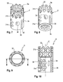
- a plurality of circular openings 2 1 a may be provided in an upper part of the first member 2 that is closer to the first end 2a.
- the circular openings 21a may be arranged in circumferential rows, wherein one row may be offset from the adjacent row.
- a plurality of diamond- or square-shaped openings 21b may be present along the wall in a region closer to the second end 2b, also in rows, wherein one row is offset from another row.
- the last row of diamond-shaped opening adjacent to the second end 2b may be cut along a circumferential line so that prongs 22 are formed that are configured to engage an end plate of a vertebral body.
- the prongs 22 may be sharpened to enhance the engagement.
- the first member 2 has a free end surface.
- An inner diameter of the first member in the region of the prongs 22 may be slightly enlarged compared to the diameter of the remaining part.
- the first member 2 comprises a thickened portion 23 that may extend from the first end 2a along, for example, more of the half of the axial length of the first member. In a circumferential direction, the thickened portion 23 may extend, for example, up to one third of the circumference of the first member 2.
- a thickness of the second portion 23 in a radial direction is such that the one or more engagement members 4 can be accommodated in the wall of the thickened portion 23.
- the size of the thickened portion 23 is not limited to the size shown in the embodiment. It can be larger or smaller depending, for example, on the size and number of the engagement members.
- two elongate openings 24 are provided in the thickened portion 23 that extend from a distance from the first end 2a to a distance from the bottom end of the thickened portion 23 in an axial direction.
- the elongate openings 24 have an axial length that allows them to be engaged with a tool (not shown) that has scissor-like arms for telescoping the implant 1 when the second member 3 is slidably received in the first member 2. It shall be contemplated that only one elongate opening 24 is present or that there is no elongate opening and the telescoping of the second member 3 relative to the first member 2 is effected otherwise.
- one or more threaded holes 25 are provided that are spaced-apart from each other in an axial direction and the centers of which are positioned on a line that is parallel to the central axis C.
- the threaded holes 25 serve for accommodating the engagement member 4 or a plurality of engagement members 4 corresponding to the number of threaded holes 25 that are adapted to the receive the engagement member 4.
- the recess 26 is open toward the top end 2a of the first member 2 and closed toward the lower end of the thickened portion 23. It provides space for an engagement portion of the engagement member 4 to extend therein and allows to mount the engagement members 4 into the first member 2 before the second member 3 is inserted into the first member 2.
- a recess 27 is present behind each of the threaded holes 25 so as to provide a larger inner diameter compared to that of the threaded hole 25.
- an abutment 26a is formed that extends in an annular manner around the threaded hole 25.
- the abutment 26a has the function of cooperating with a portion of the engagement member 4 as described below.
- the recesses 27 a space is formed between the abutment 26a and an outer wall of the second tubular member 3. The dimension of the recesses 27 and of the axial recess 26 in a radial direction from the central axis C is such that the engagement members 4 can move from the threaded hole 25 toward the second member 3
- the recesses 26, 27 of the thickened portion 23 form together with the outer wall of the second member 3 a compartment that enclose a portion of the engagement members 4, so that the engagement members 4 can also not escape to the inside of the spacer 1. It shall be noted, that small ridges 28 may be present in the inner wall of the thickened portion 23 to divide the compartment for the different engagement members 4.
- two threaded holes 25 are provided in an axial direction. It shall be noted, that only one single or more than two threaded holes may also be present.
- a small transverse through-hole 60 may be provided that serves for receiving a pin 61 that has a length so that one end thereof extends into the interior hollow portion of the first member 2 and into an elongate recess of the second member 3.
- the function of the pin 61 may be twofold. First, it maintains the alignment of the first member 2 and the second member 3 in a circumferential direction. Second, it may limit the overall length-adjustment so that a disengagement of the first member 2 and the second member 3 can not occur.
- the second tubular member 3 has a first end 3 a and an opposite second end 3b, a central axis C that coincides in the assembled state with the central axis C of the first member 2, a hollow interior and a wall defined by the tube.
- the second end 3b faces toward the second end 2b of the first tubular member 2.
- the second member 3 also comprises a plurality of openings, wherein a first group of openings 31a may be circular and is arranged in rows offset from each other in a region closer to the second end 3b, and wherein a second group of openings 31b is substantially diamond-shaped or square-shaped and is arranged in a region closer to the first end 3a.
- the second tubular member 3 comprises prongs 32 at the first end that may be generated by cutting one row of diamond-shaped openings 31b in the center so that the plurality of prongs 32 remain.
- the prongs 32 may be sharpened and serve for engagement with a vertebral end plate.
- two circumferentially spaced apart elongate openings 34 are provided, the axial length of which is smaller than the axial length of the elongate openings 24 of the first member 2.
- the elongate openings 34 serve for engagement with the tool that distracts the second member 3 and the first member 2.
- the recesses 35 are spherical segment-shaped and are arranged in a line parallel to the central longitudinal axis C of the spacer 1. Moreover, the recesses 35 are formed side by side and have a depth less than a radius thereof. In the assembled state, as shown in Figs. 2 and 15a , the line of recesses 35 extends at least over the same length as the line of threaded holes 25. The line of recesses 35 forms a ratchet-like engagement portion on the second member 3 that cooperates with an engagement portion of the engagement member 4.
- an elongate recess 36 is formed in the outer wall of the second member 3 that does not extend completely through the wall.
- the elongate recess 36 serves for accommodating a front end of the pin 61 that is mounted into the pin hole 60 of the first member 2.
- An inner diameter of the second member 3 in the region of the prongs 32 up to a distance from the first end 3 a may be slightly larger than an inner diameter of the second member in the region of the line of recesses 35.
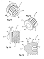
- the engagement member 4 is a monolithic part that comprises a first end 4a and an opposite second end 4b. It is basically a set screw having a threaded first portion 41 adjacent to the first end 4a with an outer thread that cooperates with the inner thread of the threaded hole 25 of the first member 2. At the first end 4a, as common for set screws, an engagement recess 42 for a driver is provided. Between the first portion 41 and the second end 4b, a cylindrical collar 43 extends outward and beyond the threaded portion 41 in a radial direction. The collar 41 has an outer diameter that is greater than the outer diameter of the threaded portion 41.
- a surface portion 43a of the collar 43 that faces toward the first end 4a serves as an abutment that cooperates with the abutment 26a in the inner wall of the thickened portion 23 of the first member 2.
- a spherical segment-shaped portion or ball-shaped projection 44 is provided that forms an engagement portion for engagement with the engagement portion that is provided by the axial line of recesses 35 in the first member.
- the engagement projection 44 fits into the spherical segment-shaped recesses 35 as illustrated in Fig. 15b .
- a total length of the engagement member 4 in a direction of the screw axis of the engagement member 4 is such that, as depicted in Figs. 15b and 15c , in a first configuration the engagement projection 44 fits into the recesses 35 of the line of recesses in the second member 3 and the first end 4a is substantially flush with the outer surface of the thickened portion 23.
- the engagement member may also slightly project above the outer surface of the thickened portion 23.
- the engagement member 4 abuts with the surface 43 a against the abutment 26a provided in the inner wall of the thickened portion 23 and the engagement projection 44 is out of contact with the recesses 35.
- the threaded portion 41 may project out of the threaded hole 25. It shall be noted that it may be advantageous that the collar 43 extends fully around the screw axis, but it may also be sufficient, if the collar consists only of portions that have a limited extent in circumferential direction but still fulfil the requirement of abutting against the abutment 26a.
- All parts of the implant are made of a biocompatible metal, such as, for example, titanium or stainless steel, or of a biocompatible metal alloy, such as, for example, Nitinol. They may also be made from a biocompatible plastic material, such as, for example, polyetheretherketone (PEEK). The parts may all be made of the same or of different materials.
- a biocompatible metal such as, for example, titanium or stainless steel
- a biocompatible metal alloy such as, for example, Nitinol
- PEEK polyetheretherketone
- the spacer 1 is assembled as follows. First, the engagement member 4 or the plurality of engagement members 4 are screwed from the inside of the first tubular member 2 with their first, threaded portion 41, into the threaded holes 25 so that the engagement projections 44 are accommodated in the recess 27, preferably, such that the collar 43 abuts with its surface 43 a against the abutment 26a in the inner wall of the thickened portion 23. Thereafter, the second member 3 is inserted into the first member in such a manner that the line of recesses 35 is aligned in a circumferential direction with the centers of the threaded holes 25 of the first member 2.
- this position is secured by inserting the pin 61 into the pin-hole 60 until it engages the elongate recess 36 of the second member 3.
- the first member 2 and the second member 3 are rotationally fixed with respect to each other.
- the elongate holes 34 of the second tubular member 3 are in a circumferential direction aligned with the elongate holes 24 of the first tubular member 2.
- the spacer may be filled with bone graft before inserting it between two vertebrae.
- the spacer is used to bridge the space after removal of a vertebra.
- the spacer is inserted in a configuration where it has its minimum length.
- the first member 2 may be locked with respect to the second member 3.
- the length of the spacer 1 is adjusted.
- the engagement members 4 are screwed slightly outward to move the engagement projections 44 out of the recesses 35 so that they no longer block a movement of the second member 3 relative to the first member 2.
- the engagement members 4 can be screwed out only to such an extent to which the collar 43 abuts against the abutment 26a.
- the length-adjustment is made using a tool that engages the elongate openings 24 and 34 of the first member 2 and the second member 3, respectively.
- the tool may be a tool with scissor-like arms that can be spread in the elongate opening and thereby distract the spacer 1.
- the engagement members 4 are screwed towards the first member 1 again until the first configuration is achieved in that the engagement projection 44 engages the recesses 35 to block a further movement of the second member 3 relative to the first member 2.
- a second embodiment in the form of a length-adjustable bone plate will be explained referring to Figs. 16 and 17 . Parts and portions of the second embodiment that are identical or similar to that of the first embodiment are marked with the same reference numerals and the description thereof will not be repeated.
- the bone plate 10 comprises a first member 200, a second member 300 that is guided with respect to the first member 200 such that the first member 200 is movable relative to the second member 300 in an axial direction.
- the axial direction is defined by a longitudinal axis L that forms a central axis of a guiding structure and the main axis of the first member 200 or the second member 300.
- an engagement member 4 is provided that is identical to the engagement member of the first embodiment.
- the first member 200 comprises a top side 2a and a bottom side 2b.
- the bottom side 2b is oriented towards the bone surface and the top side 2a is facing away from the bone surface.
- the bottom side 2b may have a recessed surface portion 210 that may accommodate a portion of the second member 300 in such a manner that the second member 300 may be displaced in an axial direction substantially parallel to the bone surface with respect to the first member 200.
- a thickened portion 230 may be provided that comprises a threaded hole 250 for receiving the engagement member 4 therein.
- the bottom side 2b may have in the area of the recessed portion 210 a further recess 270 extending away from the bottom surface 210 to provide a space for accommodating the collar 43 and the engagement projection 44 of the engagement member 4 therein.
- An area around the threaded hole 250 forms an abutment 260a for the collar 43 of the engagement member.
- An outer contour of the thickened portion 230 may be substantially cuboid-shaped.
- projections 240 may be provided that can engage a guiding structure formed on the second member 300.
- the first member 200 may further have one or a plurality of holes 290 that serve for the accommodation of heads of bone screws (not shown) therein for fixing the bone plate to the bone.
- the second member 300 comprises a top side 3a and a bottom side 3b, wherein at least a portion of the bottom side has a surface that is substantially flush with the lowermost portion of the bottom side 2b of the first member 200.
- a groove 310 is provided that serves for guiding the first member 200 therein in an axial direction to allow the adjustment of the overall length of the bone plate.
- the groove 310 has small inwardly extending projections 311 on each side that extend slightly over the projections 240 so that the first member is safely guided.
- an axial line of spherical segment-shaped recesses 350 is provided on the top side 3a.
- the line of recesses 350 is aligned in a transverse direction with the center of the threaded hole 250 such that the engagement portion 44 of the engagement member 4 can engage the recesses 350.
- the second member 300 may also have one or more holes 360 extending from the topside 3 a to the bottom side 3b for accommodating bone screws therein. It shall be noted that various different shapes may be contemplated for the first and the second member. The shape is in any case not limited to the shape shown in Figs. 16 and 17 .
- the engagement member that has been inserted before assembly of the bone plate into the threaded hole 250 of the first member can assume two configurations.
- a first configuration shown in Fig. 17
- the engagement member is screwed towards the second member 300 until its engagement projection 44 engages one of the recesses of the line of recesses 350.
- the first member 200 is locked with respect to the second member 300.
- the engagement member 4 is screwed back until the collar 43 abuts against the abutment surface 260 provided at the inside of the inner wall of the thickened portion 230.
- the projection 44 is out of contact with the recesses 350 and the first member 200 can be displaced in the axial direction relative to the second member 300.
- the collar 43 prevents inadvertent disengagement of the engagement member 4 from the first member 200. This enhances the safety of use of the implant.
- the collar 43 may be annular or may be provided only in circumferentially limited portions.
- the ratchet-like recesses may have a different shape as well as the engagement projection of the engagement member.
- the recesses do not need to have a circular shape but can be notch-like or otherwise shaped.
- the engagement projection of the engagement member may have any shape that is suitable to cooperate with the recesses.
- engagement projections of the engagement member are spring-biased with regard to the remaining portions of the engagement member such that it may not be necessary to completely disengage the engagement projections from the engagement recesses when adjusting the length of the implant.
- the first member and the second member may also be interchanged, so that the engagement member may provided in the second member and the first member may have the engagement recesses.
Landscapes
- Health & Medical Sciences (AREA)
- Orthopedic Medicine & Surgery (AREA)
- Engineering & Computer Science (AREA)
- Biomedical Technology (AREA)
- Neurology (AREA)
- Life Sciences & Earth Sciences (AREA)
- Heart & Thoracic Surgery (AREA)
- Veterinary Medicine (AREA)
- Public Health (AREA)
- General Health & Medical Sciences (AREA)
- Animal Behavior & Ethology (AREA)
- Surgery (AREA)
- Transplantation (AREA)
- Vascular Medicine (AREA)
- Oral & Maxillofacial Surgery (AREA)
- Cardiology (AREA)
- Nuclear Medicine, Radiotherapy & Molecular Imaging (AREA)
- Medical Informatics (AREA)
- Molecular Biology (AREA)
- Physical Education & Sports Medicine (AREA)
- Prostheses (AREA)
Priority Applications (6)
| Application Number | Priority Date | Filing Date | Title |
|---|---|---|---|
| ES14155656.3T ES2583836T3 (es) | 2014-02-18 | 2014-02-18 | Implante de longitud ajustable |
| EP14155656.3A EP2907480B1 (de) | 2014-02-18 | 2014-02-18 | Längenverstellbares Implantat |
| JP2015026309A JP6567287B2 (ja) | 2014-02-18 | 2015-02-13 | 変更可能な軸方向長さを有する脊椎または外傷の手術における用途のための移植片 |
| CN201510078565.6A CN104840280B (zh) | 2014-02-18 | 2015-02-13 | 长度可调节植入物 |
| KR1020150022620A KR20150097411A (ko) | 2014-02-18 | 2015-02-13 | 길이 조정 가능한 임플란트 |
| US14/624,444 US10285822B2 (en) | 2014-02-18 | 2015-02-17 | Length adjustable implant |
Applications Claiming Priority (1)
| Application Number | Priority Date | Filing Date | Title |
|---|---|---|---|
| EP14155656.3A EP2907480B1 (de) | 2014-02-18 | 2014-02-18 | Längenverstellbares Implantat |
Publications (2)
| Publication Number | Publication Date |
|---|---|
| EP2907480A1 true EP2907480A1 (de) | 2015-08-19 |
| EP2907480B1 EP2907480B1 (de) | 2016-05-25 |
Family
ID=50137504
Family Applications (1)
| Application Number | Title | Priority Date | Filing Date |
|---|---|---|---|
| EP14155656.3A Active EP2907480B1 (de) | 2014-02-18 | 2014-02-18 | Längenverstellbares Implantat |
Country Status (6)
| Country | Link |
|---|---|
| US (1) | US10285822B2 (de) |
| EP (1) | EP2907480B1 (de) |
| JP (1) | JP6567287B2 (de) |
| KR (1) | KR20150097411A (de) |
| CN (1) | CN104840280B (de) |
| ES (1) | ES2583836T3 (de) |
Cited By (1)
| Publication number | Priority date | Publication date | Assignee | Title |
|---|---|---|---|---|
| US20200306049A1 (en) * | 2017-12-15 | 2020-10-01 | Waldemar Link Gmbh & Co. Kg | Modular endoprosthesis shaft system with rotation element |
Families Citing this family (5)
| Publication number | Priority date | Publication date | Assignee | Title |
|---|---|---|---|---|
| CN108210123A (zh) * | 2016-12-22 | 2018-06-29 | 重庆润泽医药有限公司 | 多孔钽钽棒装置 |
| CN108236518A (zh) * | 2016-12-23 | 2018-07-03 | 重庆润泽医药有限公司 | 手术用钽棒装置 |
| US11457957B2 (en) * | 2020-04-11 | 2022-10-04 | Life Spine, Inc. | Spine implant with an expandable cage and expandable vertebral attachment plate providing uniform rate movement |
| CN114098933B (zh) | 2021-11-25 | 2024-11-26 | 郝定均 | 一种颈椎骨质疏松前路固定系统 |
| EP4473946B1 (de) * | 2023-06-07 | 2026-03-11 | Biedermann Technologies GmbH & Co. KG | Implantat zur verbindung zwischen wirbeln und implantatkit |
Citations (8)
| Publication number | Priority date | Publication date | Assignee | Title |
|---|---|---|---|---|
| US5964762A (en) | 1996-09-17 | 1999-10-12 | Biedermann; Lutz | Bone plate |
| US6200348B1 (en) | 1998-02-06 | 2001-03-13 | Biedermann, Motech Gmbh | Spacer with adjustable axial length |
| DE202005007809U1 (de) * | 2005-05-19 | 2005-07-28 | Aesculap Ag & Co. Kg | Implantat |
| WO2007137022A2 (en) * | 2006-05-16 | 2007-11-29 | Hammill John E | Expandable corpectomy device |
| WO2008065450A1 (en) * | 2006-11-29 | 2008-06-05 | Surgicraft Limited | Orthopaedic implants and prostheses |
| US20090164018A1 (en) * | 2007-12-19 | 2009-06-25 | Robert Sommerich | Instruments For Expandable Corpectomy Spinal Fusion Cage |
| US7803191B2 (en) | 2006-07-14 | 2010-09-28 | Biedermann Motech Gmbh | Spacer for insertion between two vertebrae |
| US8241363B2 (en) | 2007-12-19 | 2012-08-14 | Depuy Spine, Inc. | Expandable corpectomy spinal fusion cage |
Family Cites Families (6)
| Publication number | Priority date | Publication date | Assignee | Title |
|---|---|---|---|---|
| US5405391A (en) * | 1993-02-16 | 1995-04-11 | Hednerson; Fraser C. | Fusion stabilization chamber |
| US5443515A (en) * | 1994-01-26 | 1995-08-22 | Implex Corporation | Vertebral body prosthetic implant with slidably positionable stabilizing member |
| US6866682B1 (en) * | 1999-09-02 | 2005-03-15 | Stryker Spine | Distractable corpectomy device |
| US7635366B2 (en) * | 2003-12-29 | 2009-12-22 | Abdou M Samy | Plating system for bone fixation and method of implantation |
| US20080177387A1 (en) * | 2006-11-01 | 2008-07-24 | Warsaw Orthopedic, Inc. | Implants and Related Devices for Monitoring Bony Fusion |
| GB0623801D0 (en) * | 2006-11-29 | 2007-01-10 | Surgicraft Ltd | Orthopaedic implants and prosthesis |
-
2014
- 2014-02-18 EP EP14155656.3A patent/EP2907480B1/de active Active
- 2014-02-18 ES ES14155656.3T patent/ES2583836T3/es active Active
-
2015
- 2015-02-13 CN CN201510078565.6A patent/CN104840280B/zh not_active Expired - Fee Related
- 2015-02-13 JP JP2015026309A patent/JP6567287B2/ja not_active Expired - Fee Related
- 2015-02-13 KR KR1020150022620A patent/KR20150097411A/ko not_active Withdrawn
- 2015-02-17 US US14/624,444 patent/US10285822B2/en active Active
Patent Citations (8)
| Publication number | Priority date | Publication date | Assignee | Title |
|---|---|---|---|---|
| US5964762A (en) | 1996-09-17 | 1999-10-12 | Biedermann; Lutz | Bone plate |
| US6200348B1 (en) | 1998-02-06 | 2001-03-13 | Biedermann, Motech Gmbh | Spacer with adjustable axial length |
| DE202005007809U1 (de) * | 2005-05-19 | 2005-07-28 | Aesculap Ag & Co. Kg | Implantat |
| WO2007137022A2 (en) * | 2006-05-16 | 2007-11-29 | Hammill John E | Expandable corpectomy device |
| US7803191B2 (en) | 2006-07-14 | 2010-09-28 | Biedermann Motech Gmbh | Spacer for insertion between two vertebrae |
| WO2008065450A1 (en) * | 2006-11-29 | 2008-06-05 | Surgicraft Limited | Orthopaedic implants and prostheses |
| US20090164018A1 (en) * | 2007-12-19 | 2009-06-25 | Robert Sommerich | Instruments For Expandable Corpectomy Spinal Fusion Cage |
| US8241363B2 (en) | 2007-12-19 | 2012-08-14 | Depuy Spine, Inc. | Expandable corpectomy spinal fusion cage |
Cited By (3)
| Publication number | Priority date | Publication date | Assignee | Title |
|---|---|---|---|---|
| US20200306049A1 (en) * | 2017-12-15 | 2020-10-01 | Waldemar Link Gmbh & Co. Kg | Modular endoprosthesis shaft system with rotation element |
| US11654029B2 (en) * | 2017-12-15 | 2023-05-23 | Waldemar Link Gmbh & Co. Kg | Modular endoprosthesis shaft system with rotation element |
| US12257155B2 (en) | 2017-12-15 | 2025-03-25 | Waldemar Link Gmbh & Co. Kg | Modular endoprosthesis shaft system with rotation element |
Also Published As
| Publication number | Publication date |
|---|---|
| US20150230938A1 (en) | 2015-08-20 |
| JP2015150442A (ja) | 2015-08-24 |
| KR20150097411A (ko) | 2015-08-26 |
| US10285822B2 (en) | 2019-05-14 |
| CN104840280A (zh) | 2015-08-19 |
| CN104840280B (zh) | 2018-06-22 |
| ES2583836T3 (es) | 2016-09-22 |
| EP2907480B1 (de) | 2016-05-25 |
| JP6567287B2 (ja) | 2019-08-28 |
Similar Documents
| Publication | Publication Date | Title |
|---|---|---|
| EP2907480B1 (de) | Längenverstellbares Implantat | |
| US11452613B2 (en) | Vertebral implants and methods for installation thereof | |
| US12239545B2 (en) | Expandable vertebral body replacement device and method | |
| EP2851021B1 (de) | Kupplungsvorrichtung für die Verbindung einer Stange in einem Knochenverankerungselement, polyaxiale Knochenverankerungsvorrichtung und modulare Stabilisierungsvorrichtung | |
| JP6700179B2 (ja) | 椎体間固定用の装置、システム、及び方法 | |
| EP2881056A1 (de) | Verlängerungsvorrichtung eines Knochenankers, insbesondere für die minimalinvasive Chirurgie | |
| US9889018B2 (en) | Expandable vertebral body replacement device and method | |
| AU2020203215B2 (en) | Expandable vertebral body replacement device and method | |
| EP4110234B1 (de) | Expandierbare wirbelkörperersatzvorrichtung | |
| TW201532591A (zh) | 長度可調式植入物 |
Legal Events
| Date | Code | Title | Description |
|---|---|---|---|
| PUAI | Public reference made under article 153(3) epc to a published international application that has entered the european phase |
Free format text: ORIGINAL CODE: 0009012 |
|
| 17P | Request for examination filed |
Effective date: 20150521 |
|
| AK | Designated contracting states |
Kind code of ref document: A1 Designated state(s): AL AT BE BG CH CY CZ DE DK EE ES FI FR GB GR HR HU IE IS IT LI LT LU LV MC MK MT NL NO PL PT RO RS SE SI SK SM TR |
|
| AX | Request for extension of the european patent |
Extension state: BA ME |
|
| REG | Reference to a national code |
Ref country code: DE Ref legal event code: R079 Ref document number: 602014002017 Country of ref document: DE Free format text: PREVIOUS MAIN CLASS: A61F0002440000 Ipc: A61F0002460000 |
|
| GRAP | Despatch of communication of intention to grant a patent |
Free format text: ORIGINAL CODE: EPIDOSNIGR1 |
|
| RIC1 | Information provided on ipc code assigned before grant |
Ipc: A61F 2/30 20060101ALI20151102BHEP Ipc: A61F 2/46 20060101AFI20151102BHEP Ipc: A61F 2/44 20060101ALI20151102BHEP |
|
| INTG | Intention to grant announced |
Effective date: 20151127 |
|
| RBV | Designated contracting states (corrected) |
Designated state(s): AL AT BE BG CH CY CZ DE DK EE ES FI FR GB GR HR HU IE IS IT LI LT LU LV MC MK MT NL NO PL PT RO RS SE SI SK SM TR |
|
| GRAS | Grant fee paid |
Free format text: ORIGINAL CODE: EPIDOSNIGR3 |
|
| GRAA | (expected) grant |
Free format text: ORIGINAL CODE: 0009210 |
|
| AK | Designated contracting states |
Kind code of ref document: B1 Designated state(s): AL AT BE BG CH CY CZ DE DK EE ES FI FR GB GR HR HU IE IS IT LI LT LU LV MC MK MT NL NO PL PT RO RS SE SI SK SM TR |
|
| REG | Reference to a national code |
Ref country code: GB Ref legal event code: FG4D |
|
| REG | Reference to a national code |
Ref country code: CH Ref legal event code: EP Ref country code: CH Ref legal event code: NV Representative=s name: NOVAGRAAF INTERNATIONAL SA, CH |
|
| REG | Reference to a national code |
Ref country code: IE Ref legal event code: FG4D Ref country code: AT Ref legal event code: REF Ref document number: 801611 Country of ref document: AT Kind code of ref document: T Effective date: 20160615 |
|
| REG | Reference to a national code |
Ref country code: DE Ref legal event code: R096 Ref document number: 602014002017 Country of ref document: DE |
|
| REG | Reference to a national code |
Ref country code: ES Ref legal event code: FG2A Ref document number: 2583836 Country of ref document: ES Kind code of ref document: T3 Effective date: 20160922 |
|
| REG | Reference to a national code |
Ref country code: LT Ref legal event code: MG4D |
|
| REG | Reference to a national code |
Ref country code: NL Ref legal event code: MP Effective date: 20160525 |
|
| PG25 | Lapsed in a contracting state [announced via postgrant information from national office to epo] |
Ref country code: NL Free format text: LAPSE BECAUSE OF FAILURE TO SUBMIT A TRANSLATION OF THE DESCRIPTION OR TO PAY THE FEE WITHIN THE PRESCRIBED TIME-LIMIT Effective date: 20160525 Ref country code: FI Free format text: LAPSE BECAUSE OF FAILURE TO SUBMIT A TRANSLATION OF THE DESCRIPTION OR TO PAY THE FEE WITHIN THE PRESCRIBED TIME-LIMIT Effective date: 20160525 Ref country code: NO Free format text: LAPSE BECAUSE OF FAILURE TO SUBMIT A TRANSLATION OF THE DESCRIPTION OR TO PAY THE FEE WITHIN THE PRESCRIBED TIME-LIMIT Effective date: 20160825 Ref country code: LT Free format text: LAPSE BECAUSE OF FAILURE TO SUBMIT A TRANSLATION OF THE DESCRIPTION OR TO PAY THE FEE WITHIN THE PRESCRIBED TIME-LIMIT Effective date: 20160525 |
|
| REG | Reference to a national code |
Ref country code: AT Ref legal event code: MK05 Ref document number: 801611 Country of ref document: AT Kind code of ref document: T Effective date: 20160525 |
|
| PG25 | Lapsed in a contracting state [announced via postgrant information from national office to epo] |
Ref country code: PT Free format text: LAPSE BECAUSE OF FAILURE TO SUBMIT A TRANSLATION OF THE DESCRIPTION OR TO PAY THE FEE WITHIN THE PRESCRIBED TIME-LIMIT Effective date: 20160926 Ref country code: GR Free format text: LAPSE BECAUSE OF FAILURE TO SUBMIT A TRANSLATION OF THE DESCRIPTION OR TO PAY THE FEE WITHIN THE PRESCRIBED TIME-LIMIT Effective date: 20160826 Ref country code: RS Free format text: LAPSE BECAUSE OF FAILURE TO SUBMIT A TRANSLATION OF THE DESCRIPTION OR TO PAY THE FEE WITHIN THE PRESCRIBED TIME-LIMIT Effective date: 20160525 Ref country code: SE Free format text: LAPSE BECAUSE OF FAILURE TO SUBMIT A TRANSLATION OF THE DESCRIPTION OR TO PAY THE FEE WITHIN THE PRESCRIBED TIME-LIMIT Effective date: 20160525 Ref country code: LV Free format text: LAPSE BECAUSE OF FAILURE TO SUBMIT A TRANSLATION OF THE DESCRIPTION OR TO PAY THE FEE WITHIN THE PRESCRIBED TIME-LIMIT Effective date: 20160525 |
|
| PG25 | Lapsed in a contracting state [announced via postgrant information from national office to epo] |
Ref country code: SK Free format text: LAPSE BECAUSE OF FAILURE TO SUBMIT A TRANSLATION OF THE DESCRIPTION OR TO PAY THE FEE WITHIN THE PRESCRIBED TIME-LIMIT Effective date: 20160525 Ref country code: EE Free format text: LAPSE BECAUSE OF FAILURE TO SUBMIT A TRANSLATION OF THE DESCRIPTION OR TO PAY THE FEE WITHIN THE PRESCRIBED TIME-LIMIT Effective date: 20160525 Ref country code: DK Free format text: LAPSE BECAUSE OF FAILURE TO SUBMIT A TRANSLATION OF THE DESCRIPTION OR TO PAY THE FEE WITHIN THE PRESCRIBED TIME-LIMIT Effective date: 20160525 Ref country code: CZ Free format text: LAPSE BECAUSE OF FAILURE TO SUBMIT A TRANSLATION OF THE DESCRIPTION OR TO PAY THE FEE WITHIN THE PRESCRIBED TIME-LIMIT Effective date: 20160525 Ref country code: RO Free format text: LAPSE BECAUSE OF FAILURE TO SUBMIT A TRANSLATION OF THE DESCRIPTION OR TO PAY THE FEE WITHIN THE PRESCRIBED TIME-LIMIT Effective date: 20160525 |
|
| REG | Reference to a national code |
Ref country code: FR Ref legal event code: PLFP Year of fee payment: 4 |
|
| PG25 | Lapsed in a contracting state [announced via postgrant information from national office to epo] |
Ref country code: BE Free format text: LAPSE BECAUSE OF FAILURE TO SUBMIT A TRANSLATION OF THE DESCRIPTION OR TO PAY THE FEE WITHIN THE PRESCRIBED TIME-LIMIT Effective date: 20160525 Ref country code: PL Free format text: LAPSE BECAUSE OF FAILURE TO SUBMIT A TRANSLATION OF THE DESCRIPTION OR TO PAY THE FEE WITHIN THE PRESCRIBED TIME-LIMIT Effective date: 20160525 Ref country code: SM Free format text: LAPSE BECAUSE OF FAILURE TO SUBMIT A TRANSLATION OF THE DESCRIPTION OR TO PAY THE FEE WITHIN THE PRESCRIBED TIME-LIMIT Effective date: 20160525 Ref country code: AT Free format text: LAPSE BECAUSE OF FAILURE TO SUBMIT A TRANSLATION OF THE DESCRIPTION OR TO PAY THE FEE WITHIN THE PRESCRIBED TIME-LIMIT Effective date: 20160525 |
|
| REG | Reference to a national code |
Ref country code: DE Ref legal event code: R097 Ref document number: 602014002017 Country of ref document: DE |
|
| PLBE | No opposition filed within time limit |
Free format text: ORIGINAL CODE: 0009261 |
|
| STAA | Information on the status of an ep patent application or granted ep patent |
Free format text: STATUS: NO OPPOSITION FILED WITHIN TIME LIMIT |
|
| PGFP | Annual fee paid to national office [announced via postgrant information from national office to epo] |
Ref country code: FR Payment date: 20170220 Year of fee payment: 4 |
|
| 26N | No opposition filed |
Effective date: 20170228 |
|
| PG25 | Lapsed in a contracting state [announced via postgrant information from national office to epo] |
Ref country code: SI Free format text: LAPSE BECAUSE OF FAILURE TO SUBMIT A TRANSLATION OF THE DESCRIPTION OR TO PAY THE FEE WITHIN THE PRESCRIBED TIME-LIMIT Effective date: 20160525 |
|
| PGFP | Annual fee paid to national office [announced via postgrant information from national office to epo] |
Ref country code: IT Payment date: 20170228 Year of fee payment: 4 Ref country code: ES Payment date: 20170220 Year of fee payment: 4 |
|
| PG25 | Lapsed in a contracting state [announced via postgrant information from national office to epo] |
Ref country code: MC Free format text: LAPSE BECAUSE OF FAILURE TO SUBMIT A TRANSLATION OF THE DESCRIPTION OR TO PAY THE FEE WITHIN THE PRESCRIBED TIME-LIMIT Effective date: 20160525 |
|
| REG | Reference to a national code |
Ref country code: IE Ref legal event code: MM4A |
|
| PG25 | Lapsed in a contracting state [announced via postgrant information from national office to epo] |
Ref country code: LU Free format text: LAPSE BECAUSE OF NON-PAYMENT OF DUE FEES Effective date: 20170218 |
|
| PG25 | Lapsed in a contracting state [announced via postgrant information from national office to epo] |
Ref country code: IE Free format text: LAPSE BECAUSE OF NON-PAYMENT OF DUE FEES Effective date: 20170218 |
|
| PG25 | Lapsed in a contracting state [announced via postgrant information from national office to epo] |
Ref country code: MT Free format text: LAPSE BECAUSE OF NON-PAYMENT OF DUE FEES Effective date: 20170218 |
|
| PG25 | Lapsed in a contracting state [announced via postgrant information from national office to epo] |
Ref country code: AL Free format text: LAPSE BECAUSE OF FAILURE TO SUBMIT A TRANSLATION OF THE DESCRIPTION OR TO PAY THE FEE WITHIN THE PRESCRIBED TIME-LIMIT Effective date: 20160525 |
|
| REG | Reference to a national code |
Ref country code: FR Ref legal event code: ST Effective date: 20181031 |
|
| PG25 | Lapsed in a contracting state [announced via postgrant information from national office to epo] |
Ref country code: IT Free format text: LAPSE BECAUSE OF NON-PAYMENT OF DUE FEES Effective date: 20180218 Ref country code: FR Free format text: LAPSE BECAUSE OF NON-PAYMENT OF DUE FEES Effective date: 20180228 |
|
| PG25 | Lapsed in a contracting state [announced via postgrant information from national office to epo] |
Ref country code: HU Free format text: LAPSE BECAUSE OF FAILURE TO SUBMIT A TRANSLATION OF THE DESCRIPTION OR TO PAY THE FEE WITHIN THE PRESCRIBED TIME-LIMIT; INVALID AB INITIO Effective date: 20140218 |
|
| REG | Reference to a national code |
Ref country code: ES Ref legal event code: FD2A Effective date: 20190801 |
|
| PG25 | Lapsed in a contracting state [announced via postgrant information from national office to epo] |
Ref country code: BG Free format text: LAPSE BECAUSE OF FAILURE TO SUBMIT A TRANSLATION OF THE DESCRIPTION OR TO PAY THE FEE WITHIN THE PRESCRIBED TIME-LIMIT Effective date: 20160525 |
|
| PG25 | Lapsed in a contracting state [announced via postgrant information from national office to epo] |
Ref country code: CY Free format text: LAPSE BECAUSE OF FAILURE TO SUBMIT A TRANSLATION OF THE DESCRIPTION OR TO PAY THE FEE WITHIN THE PRESCRIBED TIME-LIMIT Effective date: 20160525 Ref country code: ES Free format text: LAPSE BECAUSE OF NON-PAYMENT OF DUE FEES Effective date: 20180219 |
|
| PG25 | Lapsed in a contracting state [announced via postgrant information from national office to epo] |
Ref country code: MK Free format text: LAPSE BECAUSE OF FAILURE TO SUBMIT A TRANSLATION OF THE DESCRIPTION OR TO PAY THE FEE WITHIN THE PRESCRIBED TIME-LIMIT Effective date: 20160525 |
|
| PG25 | Lapsed in a contracting state [announced via postgrant information from national office to epo] |
Ref country code: TR Free format text: LAPSE BECAUSE OF FAILURE TO SUBMIT A TRANSLATION OF THE DESCRIPTION OR TO PAY THE FEE WITHIN THE PRESCRIBED TIME-LIMIT Effective date: 20160525 |
|
| PG25 | Lapsed in a contracting state [announced via postgrant information from national office to epo] |
Ref country code: HR Free format text: LAPSE BECAUSE OF FAILURE TO SUBMIT A TRANSLATION OF THE DESCRIPTION OR TO PAY THE FEE WITHIN THE PRESCRIBED TIME-LIMIT Effective date: 20160525 |
|
| PG25 | Lapsed in a contracting state [announced via postgrant information from national office to epo] |
Ref country code: IS Free format text: LAPSE BECAUSE OF FAILURE TO SUBMIT A TRANSLATION OF THE DESCRIPTION OR TO PAY THE FEE WITHIN THE PRESCRIBED TIME-LIMIT Effective date: 20160925 |
|
| P01 | Opt-out of the competence of the unified patent court (upc) registered |
Effective date: 20230525 |
|
| REG | Reference to a national code |
Ref country code: CH Ref legal event code: U11 Free format text: ST27 STATUS EVENT CODE: U-0-0-U10-U11 (AS PROVIDED BY THE NATIONAL OFFICE) Effective date: 20260301 |
|
| PGFP | Annual fee paid to national office [announced via postgrant information from national office to epo] |
Ref country code: GB Payment date: 20260213 Year of fee payment: 13 |
|
| PGFP | Annual fee paid to national office [announced via postgrant information from national office to epo] |
Ref country code: DE Payment date: 20260224 Year of fee payment: 13 |
|
| PGFP | Annual fee paid to national office [announced via postgrant information from national office to epo] |
Ref country code: CH Payment date: 20260301 Year of fee payment: 13 |