EP2907402B1 - Helm mit Aufprallverfolgung - Google Patents
Helm mit Aufprallverfolgung Download PDFInfo
- Publication number
- EP2907402B1 EP2907402B1 EP15153888.1A EP15153888A EP2907402B1 EP 2907402 B1 EP2907402 B1 EP 2907402B1 EP 15153888 A EP15153888 A EP 15153888A EP 2907402 B1 EP2907402 B1 EP 2907402B1
- Authority
- EP
- European Patent Office
- Prior art keywords
- helmet
- force
- impact
- injury
- shock absorbers
- Prior art date
- Legal status (The legal status is an assumption and is not a legal conclusion. Google has not performed a legal analysis and makes no representation as to the accuracy of the status listed.)
- Active
Links
Images


Classifications
-
- A—HUMAN NECESSITIES
- A42—HEADWEAR
- A42B—HATS; HEAD COVERINGS
- A42B3/00—Helmets; Helmet covers ; Other protective head coverings
- A42B3/04—Parts, details or accessories of helmets
- A42B3/0406—Accessories for helmets
- A42B3/0433—Detecting, signalling or lighting devices
- A42B3/046—Means for detecting hazards or accidents
-
- A—HUMAN NECESSITIES
- A42—HEADWEAR
- A42B—HATS; HEAD COVERINGS
- A42B3/00—Helmets; Helmet covers ; Other protective head coverings
- A42B3/04—Parts, details or accessories of helmets
- A42B3/10—Linings
- A42B3/12—Cushioning devices
- A42B3/125—Cushioning devices with a padded structure, e.g. foam
- A42B3/128—Cushioning devices with a padded structure, e.g. foam with zones of different density
-
- G—PHYSICS
- G01—MEASURING; TESTING
- G01L—MEASURING FORCE, STRESS, TORQUE, WORK, MECHANICAL POWER, MECHANICAL EFFICIENCY, OR FLUID PRESSURE
- G01L5/00—Apparatus for, or methods of, measuring force, work, mechanical power, or torque, specially adapted for specific purposes
- G01L5/0052—Apparatus for, or methods of, measuring force, work, mechanical power, or torque, specially adapted for specific purposes measuring forces due to impact
-
- A—HUMAN NECESSITIES
- A42—HEADWEAR
- A42B—HATS; HEAD COVERINGS
- A42B3/00—Helmets; Helmet covers ; Other protective head coverings
- A42B3/04—Parts, details or accessories of helmets
- A42B3/10—Linings
- A42B3/12—Cushioning devices
- A42B3/125—Cushioning devices with a padded structure, e.g. foam
-
- A—HUMAN NECESSITIES
- A61—MEDICAL OR VETERINARY SCIENCE; HYGIENE
- A61B—DIAGNOSIS; SURGERY; IDENTIFICATION
- A61B5/00—Measuring for diagnostic purposes; Identification of persons
- A61B5/16—Devices for psychotechnics; Testing reaction times ; Devices for evaluating the psychological state
- A61B5/163—Devices for psychotechnics; Testing reaction times ; Devices for evaluating the psychological state by tracking eye movement, gaze, or pupil change
-
- A—HUMAN NECESSITIES
- A61—MEDICAL OR VETERINARY SCIENCE; HYGIENE
- A61B—DIAGNOSIS; SURGERY; IDENTIFICATION
- A61B5/00—Measuring for diagnostic purposes; Identification of persons
- A61B5/74—Details of notification to user or communication with user or patient; User input means
- A61B5/7465—Arrangements for interactive communication between patient and care services, e.g. by using a telephone network
-
- G—PHYSICS
- G08—SIGNALLING
- G08B—SIGNALLING SYSTEMS, e.g. PERSONAL CALLING SYSTEMS; ORDER TELEGRAPHS; ALARM SYSTEMS
- G08B21/00—Alarms responsive to a single specified undesired or abnormal condition and not otherwise provided for
- G08B21/18—Status alarms
- G08B21/182—Level alarms, e.g. alarms responsive to variables exceeding a threshold
Definitions
- This application relates to a helmet and more particularly to a helmet having built in capabilities to track impact history and/or built in capabilities to test for brain injury.
- the helmet can also have varying shock absorption capabilities.
- Head injuries in sports are becoming more prevalent. Part of the reason for such increase in incidence of injuries is that helmets provide a false sense of security and are therefore used offensively in contact sports such as football. When two helmets crash together, full force transmission occurs, leading to concussions and more severe head injuries.
- US2013/0110415 discloses apparatus for monitoring head acceleration and/or forces acting thereon.
- a device for monitoring an acceleration or a force acting on the head of a user includes a flexible article adapted to be worn on the head of the user; and a monitoring assembly coupled to the flexible article.
- the monitoring assembly includes a sensor for measuring a force on the head and transmitting data relating to the force, the sensor disposed proximate to the head, a processor adapted to receive the force data from the sensor, and a flexible strip operatively connecting the sensor and the processor.
- US2008/0256687 discloses a helmet which includes a shell configured to be worn on a head of a user and a sensor coupled to the shell.
- the sensor is configured to detect deceleration of the shell below a predetermined threshold rate of deceleration and to generate a signal.
- the helmet further includes a communication module coupled to the shell and the sensor.
- the communication module is configured to receive the signal from the sensor when the sensor detects a deceleration of the shell below a predetermined threshold rate of deceleration and to generate a signal to a rescue assistance center after a predetermined time period.
- US5950244 discloses a protective device comprising a shell and a liner.
- the shell includes an interior surface.
- the liner is associated with the interior surface of the shell and includes a member for enabling controlled displacement of preselected regions of the liner upon various degrees of impact of the protective device.
- the controlled displacement member comprises a first member and a second member, each of the first and second members having a top surface, a bottom surface and a different impact absorbing characteristic.
- the top surface of at least one of the first and second members is associated with the interior surface of the shell. At least a portion of the bottom surface of the first member extends further from the interior surface of the shell and the bottom surface of the second member.
- US2013/0074248 discloses an impact sensing device which includes a plurality of accelerometers orthogonally oriented with respect to each other and attachable at a body location, each capable of producing signals indicative of impacts.
- An integrated circuit is configured to determine the magnitude and direction of the impacts based on the signals and operative to activate an indicator when the magnitude exceeds a first threshold based on the direction of the impact and when the magnitude exceeds a second threshold more than a selected number of times.
- a head injury coefficient is determined based on the magnitude and a duration of the impact, and the threshold level of acceleration is expressed in terms of a head injury coefficient value, which is determined by empirically correlating a head injury coefficient measured at the body location and a head injury coefficient measured at the centre of mass of a human head resulting from an impact.
- US2002/0060633 discloses a system and method for determining the magnitude of linear and rotational acceleration of and direction of impact to a body part, such as a head, includes positioning a number of single-axis accelerometers proximate to the outer surface of the body part. A number of accelerometers are oriented to sense respective linear acceleration orthogonal to the outer surface of the body part. The acceleration data sensed is collected and recorded and a hit profile is determined from the configuration of the body part and the positioning of the plurality of accelerometers thereabout. A number of potential hit results are generated from the hit profile function and then compared to the acceleration data to determine a best fit hit result, which yields the magnitude of linear acceleration to and direction of an impact to the body part.
- the rotational acceleration of the body part can also be estimated from the magnitude of linear acceleration of and direction of the impact to the body part.
- US2013/0282308 discloses head impact event evaluation systems and methods.
- a system and computer implemented method for event detection includes collecting sensor data transmitted from one or more sensor devices being attached to one or more users. The sensors transmit data when an event results in sensor data above a threshold value. At least one force is determined based on the collected sensor data. At least one force vector is determined based on a location of one or more sensors associated with the sensor devices and the determined at least one of the linear or rotational force. At least a portion of a human form is displayed with the determined force vector based on the determined at least one force vector on a display.
- US2013/0060168 discloses the monitoring of at least one physiological parameter of a person engaged in a physical activity, for example an impact received by a player engaged in a contact sport such as football.
- the system includes a monitoring unit that actively monitors the physiological parameter of the person, wherein the monitoring unit generates an alert event when the monitored physiological parameter exceeds a threshold of the parameter.
- the monitoring unit determines whether the parameter exceeds an over-exposure threshold, wherein the threshold is based upon both a single incidence or cumulative incidences.
- the present invention overcomes the problems and disadvantages of the prior art.
- a helmet for tracking impact comprising at least one sensor, a processor in communication with the sensor, a storage file in communication with the processor, and an alarm system in communication with the processor, the at least one sensor measuring force applied to the helmet and sending a signal to the processor indicative of the measured force, the processor receiving the signal indicative of the measured force and comparing the measured force to a predetermined value, wherein if the measured force exceeds the second predetermined value a signal is sent by the processor to the alarm system to activate an alarm; and (d) if the measured force exceeds the first predetermined value but does not exceed the second predetermined value, data is sent to the storage file containing details of the force applied to the helmet.
- the data sent to the storage file further includes a time of injury.
- the measured force is one or both of a rotational force or impact force applied to a head of a wearer of the helmet and the data further includes a force value of the measured force.
- the storage file updates a register and the data is stored in the register and the register is repeatedly updated as additional data is received in response to subsequent measured forces detected which exceed a predetermined value, the data being retrievable for evaluation.
- an algorithm in the processor computes cumulative values indicative of impact history and the cumulative values are compared to threshold values, and if the cumulative values exceed the threshold values, a signal is sent to the alarm to trigger the alarm.
- the helmet may further comprise an outer shell having an inner surface and an outer surface and a plurality of shock absorbers, the shock absorbers being positioned internal of the outer shell, the plurality of shock absorbers including at least one first shock absorber having a first shock absorption characteristic and at least one second shock absorber having a second shock absorption characteristic, the second shock absorption characteristic being different than the first shock absorption characteristic, wherein the first shock absorption characteristic provides a lower activation threshold than the second shock absorption characteristic such that activation of the first and second sets of shock absorbers is dependent on the force impact to the helmet.
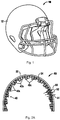
- FIG 1 illustrates a football helmet of the prior art.
- the helmet 10 has a hard outer shell 12 and soft padding inside the shell 12.
- the helmet 10 is relatively heavy and relies on the soft padding inside to cushion the head in an attempt to reduce brain injuries.
- the weight of the helmet makes the helmet cumbersome and uncomfortable to wear. The heavy weight can also adversely affect athletic performance.
- the padding inside the helmet does not provide adequate protection to the head, especially since the heavy helmet provides the wearer with a false sense of protection. This false sense of protection oftentimes lead to more head injuries since the helmet is used offensively as the wearer uses the helmet as a direct force against an opponent, and the wearer will incur direct impacts on the helmet.
- the amount of padding that can be provided in the helmet of the prior art is limited by the size of the helmet since if thicker padding is utilized it will take up more internal space, leading to even larger and more cumbersome helmet. Additionally, if such additional padding/cushioning is added, it would need to be sufficient to handle all impacts, regardless of the force. Therefore, the helmet would need to be designed with thicker cushioning throughout, even if not necessary to handle small impact forces. Also, if the helmet is designed solely to accommodate maximum impact, it will be stiffer and "bumpier" on the user's head.
- the present invention advantageously in some aspects provides a lightweight helmet without sacrificing effectiveness in injury prevention. This is achieved through the varying shock absorbers (shock absorbing members) lining the helmet, which forms the basis of EP 2 907 403 . Additionally, the helmet is designed in certain embodiments so that upon certain impact forces, the outer shell spins with respect to the helmet body, thus further dispersing the force of the impact.
- FIG. 2A-3 illustrate a first embodiment of the helmet of the present invention.
- the helmet is designated generally by reference number 20 and has a conventional face guard 22.
- Inside the outer shell 24 of the helmet 20 is an inner liner 30 which forms the shock absorbing feature of the present invention.
- Inner liner 30 has an upper surface 32 which is attached to the inner surface of the outer shell 24 and a lower surface 34 from which the shock absorbers 40 extend.
- Shock absorbers in the embodiment of Figures 2A-3 are composed of a compressible foam material with sufficient flexibility and rigidity to receive and disperse a force applied thereto.
- the shock absorbers 40 are of varying height and of varying compressibility thereby providing different shock absorbing characteristics with different activation thresholds.
- Height h2 is greater than height h1 and less than height h3.
- shock absorbers 40a, 40b and 40c are collectively referred to as shock absorbers 40.
- shock absorbers 40 For clarity, only some of the shock absorbers 40a, 40b and 40c are labeled throughout the drawings. It can be appreciated that shock absorbers of more than three differing heights can be provided. It is also contemplated that shock absorbers of only two different heights can be provided.
- the liner will have at least one, and preferably a first set of shock absorbers, having a first shock absorption characteristic, and at least another shock absorber, and preferably a second set of shock absorbers, having a second shock absorption characteristic different than the first shock absorption characteristic.
- shock absorbers 40 can be arranged in a pattern or grouping different than that the alternating pattern shown in Figures 2A-3 .
- shock absorbers 40 can be formed of a compressible foam material which compresses upon sufficient impact.
- other cushioning materials are also contemplated.
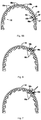
- the shock absorbers 50 of inner liner 48 include shock absorbers 50a of the smallest height g1, shock absorbers 50c of the largest height g3 and shock absorbers 50b of an intermediate height g2 which is greater than height g1 and less than height g3.
- the shock absorbers 50a, 50b and 50c are collectively referred to as shock absorbers 50.
- the shock absorbers comprise air cells rather than a foam material as in Figure 2A , and the air cells can include a relief valve.
- shock absorbing feature of Figure 5A is identical to that of Figure 2A and is used in a similar helmet as that shown in Figure 2B .
- the shock absorbing feature of Figure 5A is identical to that of Figure 2A and is used in a similar helmet as that shown in Figure 2B .
- the shock absorbing feature of Figure 5A is identical to that of Figure 2A and is used in a similar helmet as that shown in Figure 2B .
- three sets of varying shock absorbers arranged in an alternating pattern are shown, a different number of sets of varying shock absorbers and/or a different pattern is contemplated.
- Figures 6-8 illustrate what occurs upon impact of varying forces on the helmet.
- Figures 6-8 illustrate the inner liner 48 of Figure 5B
- the inner liner 30 of Figure 2A would function and react in the same manner as shown in Figures 6-8 .
- the shock absorbers 50 (like shock absorbers 40) of varying heights have different gradients of stress absorption and therefore different thresholds for activation and provide successive loading dependent on severity of force impact. Consequently, if a relatively small impact force is applied to the helmet as shown in Figure 6 , only a few of the shock absorbers would be activated, i.e., shock absorbers 50c which have the most flexibility and lowest activation threshold.
- shock absorbers 50c and the intermediate shock absorbers 50b would be affected and activated.
- smaller shock absorbers 50a would also be impacted as shock absorbers 50a have the smallest height, least flexibility and highest activation threshold. That is, all sized absorbers 50 would be activated to absorb and disperse the force. In this manner, only those shock absorbers necessary to absorb the shock would be activated, allowing for a series of smaller shock absorbers, taking up less room in the helmet and also reducing the weight of the helmet than would otherwise be necessary.
- shock absorbers 40 would be activated in the same manner as shock absorbers 50, i.e., dependent on impact force.
- shock absorbers 50 are shown impacted, however depending on the impact, only certain shock absorbers 50a, 50b, and 50c would be affected. For example, in certain instances, only the shock absorbers in the region of impact would be affected/activated. On sufficient impact, it is also possible that all shock absorbers of the liner 48 would be affected/activated. This is also applicable to liner 30 and shock absorbers 40 as well as the other shock absorbers disclosed herein, e.g., shock absorbers 60 and 70 described below.
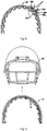
- the shock absorbers 60 of inner liner 61 are of the same height but varying shock absorption is achieved by providing different materials.
- the embodiment of Figure 5A can have the same advantages of reduced bulk as in the previously described embodiments achieved by varying the lightness of the material. It also has the advantage of varying shock absorption, wherein only a fraction of the shock absorbing elements are activated upon application of a relatively low force, i.e., the shock absorbers with the greatest flexibility/compressibility, and more shock absorbers are activated with application of a higher force i.e., including the shock absorbers having less flexibility/compressibility.
- Such varying shock absorption can be achieved using a pattern similar to that of the embodiments of Figure 2A and 5B , e.g., three sets of shock absorbers of different shock absorption characteristics arranged in an alternating pattern with a first set of first flexibility/compressibility, a second set of a different, e.g., less flexibility/compressibility and a third set of a still different, e.g., even less flexibility/compressibility. It should be appreciated that as in the aforedescribed embodiments, a different number of sets of varying shock absorbers and/or different patterns of the varying shock absorbers are also contemplated.
- the shock absorbers of the various embodiments described herein can contain material such as foam.
- the shock absorbers can contain a fluid with a relief valve for releasing pressure when the pressure is greater than a pressure threshold to reduce the effects of impact to the head.
- the relief valves allow for force deceleration and would have different thresholds for release to provide shock absorbers of varying shock absorption characteristics.
- some of the shock absorbers can contain compressible surfaces such as foam and other shock absorbers can contain fluid with a relief valve.
- the shock absorbers in accordance with the present disclosure can have different configurations, different heights and/or different materials to accommodate different forces, thus providing differential protection. They can be arranged in an alternating arrangement or grouped together in a different pattern. They can be arranged in two or more sets of varying shock absorption characteristics and can be evenly or unevenly distributed. The number of shock absorbers for each set can be the same or alternately a different number in each set.
- the inner liner with the aforedescribed shock absorbing features can be provided as a non-removable component attached to the helmet e.g., helmet 20.
- the inner liner 71 with shock absorbers 70 can be a separate component insertable into a conventional helmet 80 and attached thereto by various methods such as adhesive or clips or other methods.
- the liner 71 shown in Figure 9 has the shock absorbers of Figure 2A but other liners with other shock absorbers described herein e.g., shock absorbers 50 or 60 could also be provided as attachable and/or removable inner liners.
- the outer shell of the helmet in some embodiments can be rotatable with respect to the helmet body. This helps to deflect the force to minimize direct hit impact. This is shown for example in Figures 4B and 4C , represented by the directional arrow showing for example a front impact causing rotation of the outer body 84 with respect to the inner liner 86 and Figure 4C illustrating rotation of the outer body 84 upon a rear impact force.
- the outer shells of the helmets of the other embodiments disclosed herein (with associated shock absorbers) can likewise in some embodiments be rotatably mounted to the helmet body so they can rotate as in Figures 4B and 4C .
- any of the aforedescribed helmets can have a low friction outer surface, and even an enhanced slippery outer surface, by providing a low friction coating or low friction outer layer to aid in a glancing or deflecting rather than a direct hit. That is, the lower friction outer surface deflects the force to the helmet.
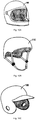
- FIGS 10A-10C show examples of different helmets which can contain any of the inner liners and shock absorbers described herein, either permanently attached or as an attachable (mountable) insert as in Figure 9 .
- Figure 10A illustrates a motorcycle helmet 100
- Figure 10B illustrates a bicycle helmet 110
- Figure 10C illustrates a baseball batter's helmet 130.
- Other helmets are also contemplated including for example helmets for lacrosse, field hockey, etc.
- FIGs 11-14 illustrate flow charts of various embodiments of helmets of having impact tracking capabilities and Figures 15-17 are schematic block diagrams of the systems of Figures 11-14 .
- the helmets of these embodiments can be used in combination with the helmets of varying shock absorption features of Figures 1-10 described above or alternatively can be used with helmets without the varying shock absorption features described above. In either case, the helmets as disclosed in Figures 11-18 track and store impact history of the wearer to thereby prevent further injury to the wearer.
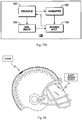
- Figure 18 illustrates by way of example a helmet containing a sensor for measuring impact and an injury tracking system discussed in detail below.
- Figure 18 also illustrates three sets of shock absorbers corresponding to the shock absorbers of Figure 5B to provide varying shock absorbing characteristics as described above.
- the other aforedescribed shock absorbers can also be utilized.
- shock absorbers of Figures 1-10 would not be utilized and conventional shock absorption would be utilized in the helmets of Figures 11-18 .
- Note the various types of helmets of Figures 10A-10C with or without the aforedescribed shock absorbers, as well as helmets for other uses, can also contain the sensors, storage file and impact tracking of the present invention.
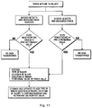
- the system provided in the helmet is illustrated in the schematic block diagram of Figure 15 and in the flow chart of Figure 11 .
- the helmet wearer's history is tracked and stored within the helmet. That is, information relating to helmet impact can be tied to the player's career and tag coded to the individual.
- a force is applied to the helmet, which can be in the form of an external impact, e.g., a direct blow to the head, or in the form of a rotational force, e.g., a jerking motion to the head
- a sensor(s) within the helmet detects and measures such force.
- One or more sensors can be provided and located in various locations in or on the helmet.
- the sensor 112 sends a signal to the processor 100 indicative of the measured rotational force.
- the processor 100 receives the signal indicative of the measured rotational force R2 where it is compared to a predetermined or threshold value R1. If the rotational force value R2 does not exceed such predetermined value R1, then it is determined (computed) a "non-event" and no data is transferred by the processor 100 to the storage file 114. This ensures that minor movements of the head which have no actual or cumulative effect on the wearer are not added to the storage file (memory) and skew future comparative analysis.
- the measured force value R2 exceeds the predetermined value R1
- the data is sent to the storage file 114 to record one or more, and preferably all, of the following data: 1) the type of injury; 2) the exact location of the injury; 3) the date and time of injury; and 4) the force value.
- the storage file is updated to add this information, i.e., type, location, date/time of injury and force, to the existing register so a cumulative record can be maintained, thereby tracking the wearer's history.
- the storage file updates a register to include the data in the register.
- the register is repeatedly updated as additional data is received in response to subsequent measured forces exceeding the predetermined value. The register enables that at any given time, the player's injury history can be retrieved from memory, and reviewed and evaluated and necessary steps can be taken to prevent further injury.
- the sensor 110 sends a signal to the processor 100 indicative of the measured impact force F2.
- the processor 100 receives the signal indicative of the measured force F2 where it is compared to a predetermined or threshold force value F1. If the force F2 does not exceed such predetermined value F1, then it is determined (computed) a "non-event" and no data is transferred to the storage file 114. This ensures that minor impact to the head which have no actual or cumulative effect on the wearer are not added to memory and skew future comparative analysis.
- the measured force value F2 exceeds the predetermined value F1
- the data is transferred to the storage file to record one or more, and preferably all, of the following data: 1) the type of injury; 2) the exact location of the injury; 3) the date and time of injury; and 4) the force value.
- the storage file 114 is updated to add this information, i.e., type, location, date/time of injury and force, to the existing register so a cumulative record can be maintained.
- Such recordation and storage has the advantages identified above with evaluation of rotational force R2. In this manner, at any given time, the player's injury history can be retrieved from memory, reviewed and evaluated and necessary steps can be taken to prevent further injury.
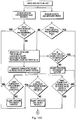
- FIG. 12 An embodiment of the helmet and impact tracking system contained therein according to the present invention is depicted in the flow chart of Figure 12 and schematic block diagram of Figure 16 .
- the system and method includes an alarm system 124 provided in the helmet so that the wearer and others are alerted to the danger or potential danger of brain injury.
- cumulative calculations are performed to compute cumulative effect of impact and injury.
- the alarm of this system can be triggered by a single impact incident or triggered by a cumulative calculation of one or more measured incidents/impacts.
- a sensor(s) 112 detects and measures head rotation and/or external force applied to the helmet as in the embodiment of Figure 11 .
- the measured rotational force R4 is sent via a first signal to the processor 120.
- the processor 120 receives the signal indicative of the measured rotational force R4 where it is compared to a predetermined or threshold value R3. (Note that R4 can be the same as R2 of Figure 11 or alternatively another value).
- the threshold value R3 can be the same or different than R1 of the embodiment of Figure 11 . If the measured rotational force R4 exceeds the threshold value R3, a second signal is sent by the processor 120 to the alarm system 124 to trigger the alarm.
- the alarm can be of various forms such as audible, e.g.
- a beeping sound, or visual, e.g., a light or LED can be illuminated in the helmet.
- the sensor 110 detects an external impact force F4 to the helmet, the sensor 110 measures the force and sends a first signal to the processor 120 indicative of the measured external force F4 where it is compared to a predetermined or threshold value F3.
- F4 can be the same as F2 of Figure 11 or alternatively another value.
- the threshold value F3 can be the same or different than threshold value F1 of the embodiment of Figure 11 . If the measured force F4 exceeds the threshold value F3, a second signal is sent to the alarm system 124 to trigger the alarm.
- the data is transferred to the storage file 122 to enable cumulative calculations.
- the data storage file 122 in the helmet is updated to record one or more, and preferably all, of the following data (parameters): 1) the type of injury; 2) the location of the injury; 3) the date and time of injury; and 4) the force value, and then a cumulative total of each of these parameters is calculated and stored in the file. Once the cumulative value of each of these incidents/parameters is generated, which is representative of the wearer's personal history of injury incidents, it is compared to a predetermined or threshold value correlating to a safe cumulative value.
- the processor 120 includes an algorithm to perform these computations and compare them to either individual cumulative values for each parameter or compute a value based on a combination of one or more of the parameters. For example, if the cumulative value of any one of these parameters, e.g., frequency of impact/injury, exceeds a threshold cumulative value of such frequency, then a signal is sent to trigger the alarm. On the other hand, if none of the cumulative values exceed the threshold value, then the alarm is not triggered, but the storage file remains updated with the new data so the values can be recalculated upon receipt of new data in response to subsequent impact to access if an alarm situation is warranted.
- a threshold cumulative value of such frequency e.g., a threshold cumulative value of such frequency
- the processor can evaluate the combination of the parameters (data) in accordance with the algorithm to evaluate whether the combination of two or more of the cumulative values will trigger an "event” thereby activating the alarm system 124.
- the system of Figure 12 can be configured in alternate embodiments that if the head rotation R4 or impact force F4 exceeds the values R3 and F3, and the alarm system 114 is triggered, these values are transmitted to the storage file 122 and considered in the cumulative calculations generated. This ensures that the forces which trigger the alarm remain part of the impact history.
- the flow chart of Figure 12 would include an arrow that in addition to sending a signal to trigger an alarm (in response to the first decision box), would also show data being sent to the storage file to update the record.
- the predetermined value R3 and F3 are different, i.e., greater, than the first predetermined values R1 and F1 of Figure 11 . That is, in such embodiments, a comparative analysis is first made by the processor 120 to determine if this first (lower) predetermined value R1, F1 is exceeded. If it is exceeded, than a comparison is made to R3 and F3 and the foregoing steps of Figure 12 apply.
- FIG. 13 and 14 provide an injury tracking system where the helmet wearer's injury can be assessed right on site. That is, the helmet contains software to assess brain injury patterns by various methods such as an eye tracking system to assess the focusing/concentration ability of the wearer, a motion tracking system to determine if the user can follow a set of verbal commands to move parts of his body, a hearing testing system to determine the wearer's response to commands, a verbal testing system to determine the wearer's verbal response to questions and/or commands, as well as other forms of testing the wearer, including a smell test emitter of a stimulant gas or liquid. As can be appreciated, such systems can utilize for example, visual, verbal, olfactory and/or auditory testing.
- one or more sensors detects and measures head rotation and/or external force applied to the helmet.
- the measured rotational force is sent by the sensor 134 ( Figure 17 ) to a processor 130.
- the processor 130 receives the signal from the sensor 134 indicative of the measured rotational force R6 where it is compared to a predetermined or threshold value R5. If the measured rotational force R6 does not exceed a threshold value R5, then it is considered a "non-event" and the injury tracking system 138 is not initiated.
- the measured external force F6 received from force sensor 132 by processor 130 does not exceed a threshold value F5, then it is considered a "non-event" and the injury tracking system 138 is not initiated.
- the values R6 and F6 can be the same as R4 and F4 of the embodiment of Figure 12 or alternatively other values.
- the threshold values R5 and F5 can be the same or different than values R3 and F3 of Figure 12 .
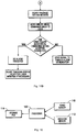
- the injury tracking system 138 is shown schematically in the block diagram of Figure 17A .
- the system 138 includes a processor 150 and a transmitter 152 to transmit commands to the wearer.
- the wearer responds (input 156) to the commands and the responses are inputted to the processor 150 for assessment.
- a data display 154 could also be provided which provides visual commands or prompts (instructions) to the wearer whose responses are inputted to the processor 150.
- the command or prompt is given to the wearer (user) such as a visual command for the user to move his hand or foot, or the user is instructed to focus his vision on various screens, such as display screen 154. If the wearer can follow the commands and satisfy the testing parameters, no alarm is triggered and the injury tracking system 138 is reset for later initiation if necessary. However, if the user cannot follow the commands within the acceptable parameters, a signal is sent to the alarm system 140 to trigger the alarm or other indicator.
- the alarm can be of various forms such as audible or visual, e.g., a beeping sound can be heard or a light or LED can be illuminated in the helmet.
- a storage file 136 could also be provided to record the type of injury, location of injury, date/time of injury and force value in the same manner as the system of Figure 11 .
- the injury tracking system is initiated either by a) initial measured force impact (as in the system of Figure 13 ) or b) by cumulative calculations of specified parameters. That is, viewed in one way, the system of Figure 14A , 14B differs from that of Figure 13 in that it also calculates cumulative history as in the system of Figure 12 , and uses these calculations to activate the injury tracking system, if necessary, not just relying on the initial measurements as in the system of Figure 13 .
- this embodiment of Figure 14A , 14B differs from that of Figure 12 in that the cumulative calculations alone are not sufficient to trigger the alarm, but instead, a test of the wearer's motor skills, focus, hearing, etc. is utilized to detect the severity of the injury, and only if the wearer's responses to the testing are determined deficient, is the alarm triggered.
- This provides on site assessment of injuries and can avoid premature initiation of an alarm since the trigger is not based solely on cumulative history but on a measurement of the wearer's functional abilities which are representative of the severity of the injury.
- a sensor detects and measures head rotation and/or external force applied to the helmet.
- the measured rotational force is compared to a first predetermined or threshold value. If the measured rotational force sent to the processor from the sensor (such as rotation sensor 134 of Figure 17 ) does not exceed a threshold value, a signal is not sent from the processor to the injury tracking system (such as injury tracking system 138 of Figure 17 ) and the injury tracking system is not initiated to activate a test for the wearer as it is computed as a "non-event.”
- the data e.g., type of injury, location of injury, date/time of injury, force value, etc., is sent to the storage file to update the register to record the data (parameters) in the same manner as in the system of Figure 12 .
- the measured external force measured by a sensor is compared by a processor to a predetermined or threshold value. If the measured force does not exceed a threshold value, a signal is not sent by the processor to the injury tracking system (such as injury tracking system 138) and the injury tracking system is not initiated to activate the test for the wearer as it is computed as a non-event.
- the data e.g., type of injury, location of injury, date/time of injury, force value, etc., is sent to the storage file to update the register to record the data (parameters) in the same manner as in Figure 12 .
- the data is transferred to the storage file to perform cumulative calculations of the type of injury, location of injury, date/time of injury and the rotational or impact force value in the same manner as described above in conjunction with the embodiment of Figure 12 .
- a cumulative total of each of these parameters is calculated, a cumulative value of each of these parameters is generated, which is representative of the wearer's personal history of injury incidents, and it is compared to a predetermined or threshold value correlating to a safe cumulative value in accordance with an algorithm which evaluates the cumulative values for each parameter as well as a combination of cumulative values to determine if the combination presents a significant injury as described above in the system of Figure 12 .
- a signal is sent to initiate the injury tracking system, and the system runs as in the embodiment of Figure 13 and Figure 17 described above, triggering an alarm or indicator if the wearer does not pass the test, i.e., does not satisfy the prompts or commands transmitted to the wearer, which is indicative of sufficient brain injury. If the cumulative values or combination values does not exceed the threshold value, then the injury tracking system is not triggered but the storage file remains updated with the new data for later addition to subsequent force impacts so the values can be recalculated to assess if activation of the tracking system is warranted at a later date.
- the measured rotational force from the sensor exceeds a threshold or predetermined value (see first decision box of Figure 14A )
- a signal is sent from the processor to the injury tracking system to activate the test for the wearer as described above in conjunction with Figure 13 .
- the measured force from the sensor exceeds a threshold or predetermined value ( Figure 14A )
- a signal is sent from the processor to the injury tracking system to activate the test for the wearer.
- the tracking system tests the wearer's motion, force/concentration, hearing, etc. in the manner described above to determine if it conforms to acceptable parameters, and if not, an alarm is triggered or other indicator is activated to alert the wearer and others that sufficient injury has occurred.
- data e.g., type, location, and date of injury and force value
- data is sent to the storage file to record the history for later retrieval from memory and evaluation.
- the foregoing helmets thus contain the wearer's information/history which is easily accessible from memory.
- the tracking system can advantageously replace the on field physician.
- the tracking system can be placed for example on Plexiglas face protector on the helmet or integrated into google type glasses on the front of the helmet.
- Figure 18 illustrates an example where the tracking system is placed on the face protector of the helmet.
- the force sensors/transducers can be placed at various regions of the helmet so as to monitor impact at any portion of the helmet.
- processor can be implemented utilizing a microprocessor, microcomputer, central processing unit or any other device that manipulates analog and/or digital signals.
- the memory module e.g., storage file, performs a storage function while the processor executes operational instructions.
- the systems disclosed herein can be wireless.
- the foregoing helmets can also include one or more cameras so that the wearer's reaction can be viewed during activation of the injury tracking system. Cameras can be aligned with the wearer to view what the wearer is visualizing, aligned with the wearer's eyes and/or additional cameras viewing from behind the wearer or to either side of the wearer.
- the helmets with impact tracking and/or injury tracking systems of Figures 11-18 can also optionally include structure to vary shock absorption and/or to diffuse and disperse the impact as in the helmets of Figures 1-10 .
- a plurality of air cells with relief valves are positioned within the helmet as described above.
- the cells can be of different characteristics so their shock absorption function is initiated depending on the extent of impact.
- the shock absorbers can alternatively be composed of compressible foam with differing flexibility/compressibility as described above.
- the outer shell can also optionally include a low friction surface to reduce the force impact by diffusing the force of a direct hit to the helmet.
- the outer shell can also optionally spin with respect to the outer body.
- the helmets of Figures 1-10 with varying shock absorption can optionally be provided with any of the systems of Figures 11-18 .
- Helmets for various sports and activities are contemplated, such as, without limitation, football, hockey, lacrosse, bicycle, motorcycle, etc. as shown for example in Figures 10A, 10B, 10C .
Landscapes
- Physics & Mathematics (AREA)
- General Physics & Mathematics (AREA)
- Helmets And Other Head Coverings (AREA)
- Force Measurement Appropriate To Specific Purposes (AREA)
Claims (4)
- Helm zur Aufprallverfolgung, der wenigstens einen Sensor (110, 112), einen Prozessor (120) in Kommunikation mit dem Sensor, eine Speicherdatei (122) in Kommunikation mit dem Prozessor und ein Alarmsystem (124) in Kommunikation mit dem Prozessor umfasst, wobei der wenigstens eine Sensor auf den Helm aufgebrachte Kraft (R4, F4) misst und ein die gemessene Kraft anzeigendes erstes Signal zum Prozessor sendet, wobei der Prozessor das die gemessene Kraft anzeigende Signal empfängt und die gemessene Kraft mit einem vorbestimmten Wert (R3, F3) vergleicht, wobei, wenn die gemessene Kraft den vorbestimmten Wert (R3, F3) übersteigt, ein zweites Signal zum Alarmsystem (124) zum Aktivieren eines Alarms gesendet wird, wobei die zur Speicherdatei (122) gesendeten Daten eine Verletzungszeit und/oder einen Kraftwert einer auf einen Kopf eines Trägers des Helms aufgebrachten Kraft beinhaltet, dadurch gekennzeichnet, dass ein Algorithmus in dem Prozessor (120) kumulative Werte berechnet, die Aufprallhistorie anzeigen, und die kumulativen Werte mit Schwellenwerten verglichen werden, und wenn die kumulativen Werte die jeweiligen Schwellenwerte übersteigen, ein drittes Signal zum Alarmsystem (124) gesendet wird, um einen Alarm auszulösen.
- Helm nach Anspruch 1, wobei, wenn die Aufprallkraft (R4, F4) einen ersten vorbestimmten Wert (R1, F1), der niedriger ist als der zweite vorbestimmte Wert (R3, F3), nicht übersteigt, dies als ein Non-Event angesehen wird und keine Daten vom Prozessor (120) zur Speicherdatei (122) übertragen werden.
- Helm nach Anspruch 1 oder 2, wobei die Speicherdatei (122) ein Register aktualisiert und die Daten im Register gespeichert werden, und wobei das Register wiederholt aktualisiert wird, während zusätzliche Daten als Reaktion auf nachfolgende erkannte gemessene Kräfte (R4, F4) empfangen werden, die einen vorbestimmten Wert (R3, F4) übersteigen, wobei die Daten zur Beurteilung abgerufen werden können.
- Helm nach einem vorherigen Anspruch, der ferner eine Außenschale (24, 84) mit einer Innenfläche und einer Außenfläche und mehrere Stoßdämpfer (40, 40a, 40b, 40c, 50, 50a, 50b, 50c, 60, 70) umfasst, wobei die Stoßdämpfer innerhalb der Außenschale positioniert sind, wobei die mehreren Stoßdämpfer wenigstens einen ersten Stoßdämpfer (40a, 50a) mit einer ersten Stoßdämpfungscharakteristik und wenigstens einen zweiten Stoßdämpfer (40c, 50c) mit einer zweiten Stoßdämpfungscharakteristik beinhalten, wobei sich die zweite Stoßdämpfungscharakteristik von der ersten Stoßdämpfungscharakteristik unterscheidet, wobei die erste Stoßdämpfungscharakteristik eine niedrigere Aktivierungsschwelle bereitstellt als die zweite Stoßdämpfungscharakteristik, so dass eine Aktivierung des ersten und zweiten Satzes von Stoßdämpfern von der auf den Helm aufprallenden Kraft abhängig ist.
Applications Claiming Priority (3)
| Application Number | Priority Date | Filing Date | Title |
|---|---|---|---|
| US201461940407P | 2014-02-15 | 2014-02-15 | |
| US201461991463P | 2014-05-10 | 2014-05-10 | |
| US14/604,557 US10413009B2 (en) | 2014-02-15 | 2015-01-23 | Helmet with impact tracking |
Publications (2)
| Publication Number | Publication Date |
|---|---|
| EP2907402A1 EP2907402A1 (de) | 2015-08-19 |
| EP2907402B1 true EP2907402B1 (de) | 2019-06-12 |
Family
ID=52446283
Family Applications (1)
| Application Number | Title | Priority Date | Filing Date |
|---|---|---|---|
| EP15153888.1A Active EP2907402B1 (de) | 2014-02-15 | 2015-02-05 | Helm mit Aufprallverfolgung |
Country Status (3)
| Country | Link |
|---|---|
| US (2) | US10413009B2 (de) |
| EP (1) | EP2907402B1 (de) |
| JP (1) | JP2015152602A (de) |
Families Citing this family (19)
| Publication number | Priority date | Publication date | Assignee | Title |
|---|---|---|---|---|
| CA2910699A1 (en) * | 2013-04-30 | 2014-11-06 | Chester WHITE | Body impact bracing apparatus |
| US20160157545A1 (en) * | 2014-12-05 | 2016-06-09 | Michael R. Bowman | Collapsible safety helmet |
| US9552747B1 (en) * | 2015-03-13 | 2017-01-24 | Protective Sports Equipment International Inc | Helmet impact simulator and method |
| US12133566B2 (en) | 2015-10-13 | 2024-11-05 | Sports Medicine Sciences, LLC | Fluid-based exoskeletal body armor with climate control |
| US11247115B2 (en) * | 2015-10-13 | 2022-02-15 | Sports Medicine Sciences, LLC | Fluid-based exoskeletal body armor with climate control |
| GB2550411B (en) * | 2016-05-20 | 2019-04-03 | Hp1 Tech Ltd | Device for detecting a force |
| WO2018017867A1 (en) | 2016-07-20 | 2018-01-25 | Riddell, Inc. | System and methods for designing and manufacturing a bespoke protective sports helmet |
| WO2018122847A1 (en) * | 2016-12-29 | 2018-07-05 | Finkelstein Elliot Steven | A portable system and method for monitoring brain trauma |
| US11160322B2 (en) | 2017-05-04 | 2021-11-02 | John Plain | Anti-concussive helmet and alarm system therefor |
| KR102379504B1 (ko) * | 2017-08-29 | 2022-03-28 | 삼성전자 주식회사 | 충돌 분석 방법 및 장치 |
| GB2573545B (en) * | 2018-05-09 | 2022-09-07 | Rheon Labs Ltd | Impact detection |
| WO2020037279A1 (en) | 2018-08-16 | 2020-02-20 | Riddell, Inc. | System and method for designing and manufacturing a protective helmet |
| US20200093435A1 (en) * | 2018-09-25 | 2020-03-26 | University Of Maryland, Baltimore | System and method for athlete physiology monitoring |
| US11167198B2 (en) | 2018-11-21 | 2021-11-09 | Riddell, Inc. | Football helmet with components additively manufactured to manage impact forces |
| USD927084S1 (en) | 2018-11-22 | 2021-08-03 | Riddell, Inc. | Pad member of an internal padding assembly of a protective sports helmet |
| WO2020123873A1 (en) * | 2018-12-12 | 2020-06-18 | Riddell, Inc. | Systems and methods for providing training opportunities based on physiological parameter of persons engaged in physical activity |
| US20210227916A1 (en) * | 2020-01-27 | 2021-07-29 | The United States Of America, As Represented By The Secretary, Department Of Health And Human Servic | Headgear systems with air-bubble cushioning liner for improved shock absorption performance |
| CN111594572B (zh) * | 2020-05-11 | 2021-08-03 | 安徽朗巴智能科技有限公司 | 一种ar装置用防撞设备及其控制系统 |
| CA3177316A1 (en) | 2020-05-12 | 2021-11-18 | Joseph R. WORPLE | Hard hat with impact protection material |
Citations (1)
| Publication number | Priority date | Publication date | Assignee | Title |
|---|---|---|---|---|
| US20120223833A1 (en) * | 2011-02-03 | 2012-09-06 | Biju Thomas | Portable wireless personal head impact reporting system |
Family Cites Families (50)
| Publication number | Priority date | Publication date | Assignee | Title |
|---|---|---|---|---|
| US3713640A (en) | 1970-07-27 | 1973-01-30 | Riddell | Energy absorbing and sizing means for helmets |
| US4012794A (en) | 1975-08-13 | 1977-03-22 | Tetsuo Nomiyama | Impact-absorbing helmet |
| GB9423113D0 (en) | 1994-11-16 | 1995-01-04 | Phillips Kenneth D | Protective headgear |
| US5669079A (en) | 1995-10-31 | 1997-09-23 | Morgan; Don E. | Safety enhanced motorcycle helmet |
| US5713082A (en) | 1996-03-13 | 1998-02-03 | A.V.E. | Sports helmet |
| US5978972A (en) | 1996-06-14 | 1999-11-09 | Johns Hopkins University | Helmet system including at least three accelerometers and mass memory and method for recording in real-time orthogonal acceleration data of a head |
| IES72949B2 (en) | 1996-11-06 | 1997-05-07 | John Francis Shortall | Safety crash helmet with automatic inflatable air bag |
| US5950244A (en) | 1998-01-23 | 1999-09-14 | Sport Maska Inc. | Protective device for impact management |
| US6826509B2 (en) | 2000-10-11 | 2004-11-30 | Riddell, Inc. | System and method for measuring the linear and rotational acceleration of a body part |
| US7526389B2 (en) * | 2000-10-11 | 2009-04-28 | Riddell, Inc. | Power management of a system for measuring the acceleration of a body part |
| US6592849B2 (en) * | 2001-06-21 | 2003-07-15 | Colgate Palmolive Company | Chewing gum to control malodorous breath |
| US6978162B2 (en) | 2001-08-17 | 2005-12-20 | Hewlett-Packard Development Company, L.P. | Integrated portable entertainment, information and communication system linked to a wireless helmet |
| DE10147045B4 (de) | 2001-09-25 | 2005-03-17 | Dräger Safety AG & Co. KGaA | Datenkommumikationssystem für Masken- oder Helmträger |
| US6798392B2 (en) | 2001-10-16 | 2004-09-28 | Hewlett-Packard Development Company, L.P. | Smart helmet |
| US6681408B2 (en) | 2002-01-25 | 2004-01-27 | Tun-Jen Ku | Impact resistant structure of safety helmet |
| US20040117896A1 (en) | 2002-10-04 | 2004-06-24 | Madey Steven M. | Load diversion method and apparatus for head protective devices |
| US20040250340A1 (en) | 2003-02-05 | 2004-12-16 | Dennis Piper | Protective headguard |
| US7093305B2 (en) | 2003-06-27 | 2006-08-22 | Morning Pride Manufacturing, L.L.C. | Protective helmet with card displaying or recording data unique to authorized wearer and readable through helmet pocket window |
| US7089602B2 (en) | 2003-06-30 | 2006-08-15 | Srikrishna Talluri | Multi-layered, impact absorbing, modular helmet |
| GB2404328A (en) | 2003-07-31 | 2005-02-02 | Scott Michael Bonnar | Helmet with inflatable lining of cells interconnected by passageways which can deform to limit pressure rise on impact |
| WO2005058083A2 (en) | 2003-12-12 | 2005-06-30 | Beck Gregory S | Safety helmet with shock detector, helmet attachement device with shock detector & methods |
| US8382685B2 (en) | 2004-02-05 | 2013-02-26 | Ggf Sports Solutions Inc. | Electronic safety device for sport-helmets |
| US20060038694A1 (en) * | 2004-08-19 | 2006-02-23 | Washington University | Electronic and microsphere-based impact detection and measurement apparatus |
| CA2590034C (en) * | 2005-01-07 | 2016-03-22 | Riddell, Inc. | System and method for evaluating and providing treatment to sports participants |
| US7570170B2 (en) | 2005-06-08 | 2009-08-04 | Delphi Technologies, Inc. | Monitoring apparatus for a helmet |
| US20070209098A1 (en) | 2006-03-10 | 2007-09-13 | Stephen Peart | Helmet having interior ventilation channels |
| US7401365B2 (en) | 2006-04-05 | 2008-07-22 | Gary Neal | Emergency information system for safety helmets |
| US20080256687A1 (en) | 2007-04-23 | 2008-10-23 | Spencer Brycen L | Helmet |
| AU2008331393B2 (en) * | 2007-12-07 | 2014-01-23 | Med-Eng, Llc | Apparatus and method for measuring and recording data from violent events |
| AU2008331392B9 (en) * | 2007-12-07 | 2014-06-12 | Med-Eng, Llc | Apparatus and method for measuring data for injury analysis |
| WO2010151631A1 (en) | 2009-06-25 | 2010-12-29 | Wayne State University | Omni-directional angular acceration reduction for protective headgear |
| US8524338B2 (en) * | 2009-11-16 | 2013-09-03 | 9Lives Llc | Impact energy attenuation system |
| US20110184319A1 (en) * | 2010-01-22 | 2011-07-28 | X2Impact, Inc. | Mouth guard with sensor |
| US20120304367A1 (en) | 2010-02-26 | 2012-12-06 | Thl Holding Company, Llc | Protective helmet |
| US8702516B2 (en) * | 2010-08-26 | 2014-04-22 | Blast Motion Inc. | Motion event recognition system and method |
| US9070269B2 (en) | 2010-11-23 | 2015-06-30 | Battle Sports Science, Llc | Impact sensing device and helmet incorporating the same |
| CA2820641C (en) | 2010-11-23 | 2019-01-15 | Battle Sports Science, Llc | Impact sensing device and helmet incorporating the same |
| WO2012100053A1 (en) * | 2011-01-19 | 2012-07-26 | X2Impact, Inc. | Headgear position and impact sensor |
| US8955169B2 (en) | 2011-02-09 | 2015-02-17 | 6D Helmets, Llc | Helmet omnidirectional energy management systems |
| US10105076B2 (en) | 2011-09-01 | 2018-10-23 | Riddell, Inc. | Systems and methods for monitoring a physiological parameter of persons engaged in physical activity |
| US9089180B2 (en) | 2011-09-08 | 2015-07-28 | Emerson Spalding Phipps | Protective helmet |
| US10024743B2 (en) | 2011-10-27 | 2018-07-17 | Reebok International Limited | Body mounted monitoring system and method |
| US8814150B2 (en) | 2011-12-14 | 2014-08-26 | Xenith, Llc | Shock absorbers for protective body gear |
| DE102012022760A1 (de) * | 2012-01-15 | 2013-07-18 | Birdy Company Gmbh | Schutzhelm und Trägerabschnitt dafür |
| US9451915B1 (en) * | 2012-02-29 | 2016-09-27 | Google Inc. | Performance of a diagnostic procedure using a wearable computing device |
| US9795178B2 (en) | 2012-03-06 | 2017-10-24 | Loubert S. Suddaby | Helmet with multiple protective zones |
| US9247780B2 (en) * | 2012-11-27 | 2016-02-02 | Gerardo Iuliano | Accessory with integrated impact detection device for a head-worn member |
| US20150040685A1 (en) * | 2013-08-08 | 2015-02-12 | Headcase Llc | Impact sensing, evaluation & tracking system |
| WO2015058135A1 (en) * | 2013-10-18 | 2015-04-23 | Brain Sentry Llc | System and method for measuring bodily impact events |
| US20150375083A1 (en) * | 2014-06-05 | 2015-12-31 | Zih Corp. | Method, Apparatus, And Computer Program Product For Enhancement Of Event Visualizations Based On Location Data |
-
2015
- 2015-01-23 US US14/604,557 patent/US10413009B2/en not_active Expired - Fee Related
- 2015-02-05 EP EP15153888.1A patent/EP2907402B1/de active Active
- 2015-02-16 JP JP2015027262A patent/JP2015152602A/ja active Pending
-
2019
- 2019-08-30 US US16/558,007 patent/US11375763B2/en active Active
Patent Citations (1)
| Publication number | Priority date | Publication date | Assignee | Title |
|---|---|---|---|---|
| US20120223833A1 (en) * | 2011-02-03 | 2012-09-06 | Biju Thomas | Portable wireless personal head impact reporting system |
Also Published As
| Publication number | Publication date |
|---|---|
| US10413009B2 (en) | 2019-09-17 |
| EP2907402A1 (de) | 2015-08-19 |
| JP2015152602A (ja) | 2015-08-24 |
| US20150230534A1 (en) | 2015-08-20 |
| US11375763B2 (en) | 2022-07-05 |
| US20200008509A1 (en) | 2020-01-09 |
Similar Documents
| Publication | Publication Date | Title |
|---|---|---|
| EP2907402B1 (de) | Helm mit Aufprallverfolgung | |
| US11064752B2 (en) | Protective helmet cap | |
| US11812808B2 (en) | Helmet including impact and health data sensing system | |
| US10292650B2 (en) | System for monitoring a physiological parameter of players engaged in a sporting activity | |
| US9026396B2 (en) | Impact sensing device and helmet incorporating the same | |
| US9247780B2 (en) | Accessory with integrated impact detection device for a head-worn member | |
| US10045740B2 (en) | Method, apparatus and system for determining a health risk using a wearable housing for sensors | |
| US10702152B2 (en) | Impact monitoring system for players engaged in a sporting activity | |
| US20140075652A1 (en) | Protective Helmet Cap | |
| US9451795B2 (en) | Impact reduction system | |
| CA2580318C (en) | System for monitoring a physiological parameter of players engaged in a sporting activity | |
| EP2592998B1 (de) | Steigerung der präsentation eines athletischen ereignisses | |
| US9070269B2 (en) | Impact sensing device and helmet incorporating the same | |
| CN103930028A (zh) | 监测从事身体活动的人的生理参数的系统和方法 | |
| US20140000011A1 (en) | Electronically controlled impact attenuating fluid containing cells for helmets | |
| US20130174329A1 (en) | Protective Helmet Cap | |
| US20150196252A1 (en) | Sensor,system and method for measuring and tracking impacts sustained by wearer | |
| US10952671B2 (en) | System for monitoring a physiological parameter of players engaged in a sporting activity | |
| EP3527096A1 (de) | Team-teilnehmerbewusstseinsindikator und indikative benachrichtigung | |
| US20180027895A1 (en) | Interactive Helmet System and Method | |
| KR20150068597A (ko) | 낙상 감지장치 및 이를 포함하는 신체 보호장비 | |
| CA2915372C (en) | Sensor, system and method for measuring and tracking impacts sustained by wearer | |
| KR20090120197A (ko) | 헤드 기어 및 이를 이용한 선수 보호 시스템 | |
| ITUB20154691A1 (it) | Casco per vigili del fuoco con sistema integrato di monitoraggio dell'operatore |
Legal Events
| Date | Code | Title | Description |
|---|---|---|---|
| PUAI | Public reference made under article 153(3) epc to a published international application that has entered the european phase |
Free format text: ORIGINAL CODE: 0009012 |
|
| AK | Designated contracting states |
Kind code of ref document: A1 Designated state(s): AL AT BE BG CH CY CZ DE DK EE ES FI FR GB GR HR HU IE IS IT LI LT LU LV MC MK MT NL NO PL PT RO RS SE SI SK SM TR |
|
| AX | Request for extension of the european patent |
Extension state: BA ME |
|
| 17P | Request for examination filed |
Effective date: 20160216 |
|
| RBV | Designated contracting states (corrected) |
Designated state(s): AL AT BE BG CH CY CZ DE DK EE ES FI FR GB GR HR HU IE IS IT LI LT LU LV MC MK MT NL NO PL PT RO RS SE SI SK SM TR |
|
| 17Q | First examination report despatched |
Effective date: 20160727 |
|
| STAA | Information on the status of an ep patent application or granted ep patent |
Free format text: STATUS: EXAMINATION IS IN PROGRESS |
|
| GRAP | Despatch of communication of intention to grant a patent |
Free format text: ORIGINAL CODE: EPIDOSNIGR1 |
|
| STAA | Information on the status of an ep patent application or granted ep patent |
Free format text: STATUS: GRANT OF PATENT IS INTENDED |
|
| INTG | Intention to grant announced |
Effective date: 20190108 |
|
| GRAS | Grant fee paid |
Free format text: ORIGINAL CODE: EPIDOSNIGR3 |
|
| GRAA | (expected) grant |
Free format text: ORIGINAL CODE: 0009210 |
|
| STAA | Information on the status of an ep patent application or granted ep patent |
Free format text: STATUS: THE PATENT HAS BEEN GRANTED |
|
| AK | Designated contracting states |
Kind code of ref document: B1 Designated state(s): AL AT BE BG CH CY CZ DE DK EE ES FI FR GB GR HR HU IE IS IT LI LT LU LV MC MK MT NL NO PL PT RO RS SE SI SK SM TR |
|
| REG | Reference to a national code |
Ref country code: GB Ref legal event code: FG4D |
|
| REG | Reference to a national code |
Ref country code: CH Ref legal event code: EP |
|
| REG | Reference to a national code |
Ref country code: AT Ref legal event code: REF Ref document number: 1141404 Country of ref document: AT Kind code of ref document: T Effective date: 20190615 |
|
| REG | Reference to a national code |
Ref country code: DE Ref legal event code: R096 Ref document number: 602015031616 Country of ref document: DE |
|
| REG | Reference to a national code |
Ref country code: IE Ref legal event code: FG4D |
|
| REG | Reference to a national code |
Ref country code: NL Ref legal event code: MP Effective date: 20190612 |
|
| REG | Reference to a national code |
Ref country code: LT Ref legal event code: MG4D |
|
| PG25 | Lapsed in a contracting state [announced via postgrant information from national office to epo] |
Ref country code: AL Free format text: LAPSE BECAUSE OF FAILURE TO SUBMIT A TRANSLATION OF THE DESCRIPTION OR TO PAY THE FEE WITHIN THE PRESCRIBED TIME-LIMIT Effective date: 20190612 Ref country code: HR Free format text: LAPSE BECAUSE OF FAILURE TO SUBMIT A TRANSLATION OF THE DESCRIPTION OR TO PAY THE FEE WITHIN THE PRESCRIBED TIME-LIMIT Effective date: 20190612 Ref country code: SE Free format text: LAPSE BECAUSE OF FAILURE TO SUBMIT A TRANSLATION OF THE DESCRIPTION OR TO PAY THE FEE WITHIN THE PRESCRIBED TIME-LIMIT Effective date: 20190612 Ref country code: NO Free format text: LAPSE BECAUSE OF FAILURE TO SUBMIT A TRANSLATION OF THE DESCRIPTION OR TO PAY THE FEE WITHIN THE PRESCRIBED TIME-LIMIT Effective date: 20190912 Ref country code: FI Free format text: LAPSE BECAUSE OF FAILURE TO SUBMIT A TRANSLATION OF THE DESCRIPTION OR TO PAY THE FEE WITHIN THE PRESCRIBED TIME-LIMIT Effective date: 20190612 Ref country code: LT Free format text: LAPSE BECAUSE OF FAILURE TO SUBMIT A TRANSLATION OF THE DESCRIPTION OR TO PAY THE FEE WITHIN THE PRESCRIBED TIME-LIMIT Effective date: 20190612 |
|
| PG25 | Lapsed in a contracting state [announced via postgrant information from national office to epo] |
Ref country code: RS Free format text: LAPSE BECAUSE OF FAILURE TO SUBMIT A TRANSLATION OF THE DESCRIPTION OR TO PAY THE FEE WITHIN THE PRESCRIBED TIME-LIMIT Effective date: 20190612 Ref country code: LV Free format text: LAPSE BECAUSE OF FAILURE TO SUBMIT A TRANSLATION OF THE DESCRIPTION OR TO PAY THE FEE WITHIN THE PRESCRIBED TIME-LIMIT Effective date: 20190612 Ref country code: BG Free format text: LAPSE BECAUSE OF FAILURE TO SUBMIT A TRANSLATION OF THE DESCRIPTION OR TO PAY THE FEE WITHIN THE PRESCRIBED TIME-LIMIT Effective date: 20190912 Ref country code: GR Free format text: LAPSE BECAUSE OF FAILURE TO SUBMIT A TRANSLATION OF THE DESCRIPTION OR TO PAY THE FEE WITHIN THE PRESCRIBED TIME-LIMIT Effective date: 20190913 |
|
| REG | Reference to a national code |
Ref country code: AT Ref legal event code: MK05 Ref document number: 1141404 Country of ref document: AT Kind code of ref document: T Effective date: 20190612 |
|
| PG25 | Lapsed in a contracting state [announced via postgrant information from national office to epo] |
Ref country code: AT Free format text: LAPSE BECAUSE OF FAILURE TO SUBMIT A TRANSLATION OF THE DESCRIPTION OR TO PAY THE FEE WITHIN THE PRESCRIBED TIME-LIMIT Effective date: 20190612 Ref country code: PT Free format text: LAPSE BECAUSE OF FAILURE TO SUBMIT A TRANSLATION OF THE DESCRIPTION OR TO PAY THE FEE WITHIN THE PRESCRIBED TIME-LIMIT Effective date: 20191014 Ref country code: SK Free format text: LAPSE BECAUSE OF FAILURE TO SUBMIT A TRANSLATION OF THE DESCRIPTION OR TO PAY THE FEE WITHIN THE PRESCRIBED TIME-LIMIT Effective date: 20190612 Ref country code: EE Free format text: LAPSE BECAUSE OF FAILURE TO SUBMIT A TRANSLATION OF THE DESCRIPTION OR TO PAY THE FEE WITHIN THE PRESCRIBED TIME-LIMIT Effective date: 20190612 Ref country code: NL Free format text: LAPSE BECAUSE OF FAILURE TO SUBMIT A TRANSLATION OF THE DESCRIPTION OR TO PAY THE FEE WITHIN THE PRESCRIBED TIME-LIMIT Effective date: 20190612 Ref country code: RO Free format text: LAPSE BECAUSE OF FAILURE TO SUBMIT A TRANSLATION OF THE DESCRIPTION OR TO PAY THE FEE WITHIN THE PRESCRIBED TIME-LIMIT Effective date: 20190612 Ref country code: CZ Free format text: LAPSE BECAUSE OF FAILURE TO SUBMIT A TRANSLATION OF THE DESCRIPTION OR TO PAY THE FEE WITHIN THE PRESCRIBED TIME-LIMIT Effective date: 20190612 |
|
| PG25 | Lapsed in a contracting state [announced via postgrant information from national office to epo] |
Ref country code: ES Free format text: LAPSE BECAUSE OF FAILURE TO SUBMIT A TRANSLATION OF THE DESCRIPTION OR TO PAY THE FEE WITHIN THE PRESCRIBED TIME-LIMIT Effective date: 20190612 Ref country code: IT Free format text: LAPSE BECAUSE OF FAILURE TO SUBMIT A TRANSLATION OF THE DESCRIPTION OR TO PAY THE FEE WITHIN THE PRESCRIBED TIME-LIMIT Effective date: 20190612 Ref country code: IS Free format text: LAPSE BECAUSE OF FAILURE TO SUBMIT A TRANSLATION OF THE DESCRIPTION OR TO PAY THE FEE WITHIN THE PRESCRIBED TIME-LIMIT Effective date: 20191012 Ref country code: SM Free format text: LAPSE BECAUSE OF FAILURE TO SUBMIT A TRANSLATION OF THE DESCRIPTION OR TO PAY THE FEE WITHIN THE PRESCRIBED TIME-LIMIT Effective date: 20190612 |
|
| REG | Reference to a national code |
Ref country code: DE Ref legal event code: R097 Ref document number: 602015031616 Country of ref document: DE |
|
| PG25 | Lapsed in a contracting state [announced via postgrant information from national office to epo] |
Ref country code: TR Free format text: LAPSE BECAUSE OF FAILURE TO SUBMIT A TRANSLATION OF THE DESCRIPTION OR TO PAY THE FEE WITHIN THE PRESCRIBED TIME-LIMIT Effective date: 20190612 |
|
| PLBE | No opposition filed within time limit |
Free format text: ORIGINAL CODE: 0009261 |
|
| STAA | Information on the status of an ep patent application or granted ep patent |
Free format text: STATUS: NO OPPOSITION FILED WITHIN TIME LIMIT |
|
| PG25 | Lapsed in a contracting state [announced via postgrant information from national office to epo] |
Ref country code: PL Free format text: LAPSE BECAUSE OF FAILURE TO SUBMIT A TRANSLATION OF THE DESCRIPTION OR TO PAY THE FEE WITHIN THE PRESCRIBED TIME-LIMIT Effective date: 20190612 Ref country code: DK Free format text: LAPSE BECAUSE OF FAILURE TO SUBMIT A TRANSLATION OF THE DESCRIPTION OR TO PAY THE FEE WITHIN THE PRESCRIBED TIME-LIMIT Effective date: 20190612 |
|
| 26N | No opposition filed |
Effective date: 20200313 |
|
| PG25 | Lapsed in a contracting state [announced via postgrant information from national office to epo] |
Ref country code: IS Free format text: LAPSE BECAUSE OF FAILURE TO SUBMIT A TRANSLATION OF THE DESCRIPTION OR TO PAY THE FEE WITHIN THE PRESCRIBED TIME-LIMIT Effective date: 20200224 Ref country code: SI Free format text: LAPSE BECAUSE OF FAILURE TO SUBMIT A TRANSLATION OF THE DESCRIPTION OR TO PAY THE FEE WITHIN THE PRESCRIBED TIME-LIMIT Effective date: 20190612 |
|
| PG2D | Information on lapse in contracting state deleted |
Ref country code: IS |
|
| REG | Reference to a national code |
Ref country code: DE Ref legal event code: R119 Ref document number: 602015031616 Country of ref document: DE |
|
| REG | Reference to a national code |
Ref country code: DE Ref legal event code: R073 Ref document number: 602015031616 Country of ref document: DE |
|
| REG | Reference to a national code |
Ref country code: CH Ref legal event code: PL |
|
| GBPC | Gb: european patent ceased through non-payment of renewal fee |
Effective date: 20200205 |
|
| REG | Reference to a national code |
Ref country code: GB Ref legal event code: S28 Free format text: APPLICATION FILED Ref country code: BE Ref legal event code: MM Effective date: 20200229 |
|
| PG25 | Lapsed in a contracting state [announced via postgrant information from national office to epo] |
Ref country code: MC Free format text: LAPSE BECAUSE OF FAILURE TO SUBMIT A TRANSLATION OF THE DESCRIPTION OR TO PAY THE FEE WITHIN THE PRESCRIBED TIME-LIMIT Effective date: 20190612 Ref country code: LU Free format text: LAPSE BECAUSE OF NON-PAYMENT OF DUE FEES Effective date: 20200205 |
|
| PG25 | Lapsed in a contracting state [announced via postgrant information from national office to epo] |
Ref country code: LI Free format text: LAPSE BECAUSE OF NON-PAYMENT OF DUE FEES Effective date: 20200229 Ref country code: CH Free format text: LAPSE BECAUSE OF NON-PAYMENT OF DUE FEES Effective date: 20200229 |
|
| REG | Reference to a national code |
Ref country code: GB Ref legal event code: S28 Free format text: RESTORATION ALLOWED Effective date: 20201230 |
|
| PG25 | Lapsed in a contracting state [announced via postgrant information from national office to epo] |
Ref country code: FR Free format text: LAPSE BECAUSE OF NON-PAYMENT OF DUE FEES Effective date: 20200229 Ref country code: GB Free format text: LAPSE BECAUSE OF NON-PAYMENT OF DUE FEES Effective date: 20200205 Ref country code: IE Free format text: LAPSE BECAUSE OF NON-PAYMENT OF DUE FEES Effective date: 20200205 Ref country code: DE Free format text: LAPSE BECAUSE OF NON-PAYMENT OF DUE FEES Effective date: 20200901 |
|
| PG25 | Lapsed in a contracting state [announced via postgrant information from national office to epo] |
Ref country code: BE Free format text: LAPSE BECAUSE OF NON-PAYMENT OF DUE FEES Effective date: 20200229 |
|
| REG | Reference to a national code |
Ref country code: DE Ref legal event code: R074 Ref document number: 602015031616 Country of ref document: DE |
|
| PG25 | Lapsed in a contracting state [announced via postgrant information from national office to epo] |
Ref country code: DE Free format text: LAPSE BECAUSE OF NON-PAYMENT OF DUE FEES Effective date: 20200901 |
|
| PGRI | Patent reinstated in contracting state [announced from national office to epo] |
Ref country code: DE Effective date: 20210402 |
|
| PGFP | Annual fee paid to national office [announced via postgrant information from national office to epo] |
Ref country code: GB Payment date: 20220216 Year of fee payment: 8 Ref country code: DE Payment date: 20220216 Year of fee payment: 8 |
|
| PG25 | Lapsed in a contracting state [announced via postgrant information from national office to epo] |
Ref country code: MT Free format text: LAPSE BECAUSE OF FAILURE TO SUBMIT A TRANSLATION OF THE DESCRIPTION OR TO PAY THE FEE WITHIN THE PRESCRIBED TIME-LIMIT Effective date: 20190612 Ref country code: CY Free format text: LAPSE BECAUSE OF FAILURE TO SUBMIT A TRANSLATION OF THE DESCRIPTION OR TO PAY THE FEE WITHIN THE PRESCRIBED TIME-LIMIT Effective date: 20190612 |
|
| PG25 | Lapsed in a contracting state [announced via postgrant information from national office to epo] |
Ref country code: MK Free format text: LAPSE BECAUSE OF FAILURE TO SUBMIT A TRANSLATION OF THE DESCRIPTION OR TO PAY THE FEE WITHIN THE PRESCRIBED TIME-LIMIT Effective date: 20190612 |
|
| REG | Reference to a national code |
Ref country code: DE Ref legal event code: R119 Ref document number: 602015031616 Country of ref document: DE |
|
| GBPC | Gb: european patent ceased through non-payment of renewal fee |
Effective date: 20230205 |
|
| PG25 | Lapsed in a contracting state [announced via postgrant information from national office to epo] |
Ref country code: GB Free format text: LAPSE BECAUSE OF NON-PAYMENT OF DUE FEES Effective date: 20230205 |
|
| PG25 | Lapsed in a contracting state [announced via postgrant information from national office to epo] |
Ref country code: GB Free format text: LAPSE BECAUSE OF NON-PAYMENT OF DUE FEES Effective date: 20230205 Ref country code: DE Free format text: LAPSE BECAUSE OF NON-PAYMENT OF DUE FEES Effective date: 20230901 |