EP2907321B1 - Système dedié à la surveillance des paramètres physiques et/ou analogiques des pieces d'un moteur - Google Patents
Système dedié à la surveillance des paramètres physiques et/ou analogiques des pieces d'un moteur Download PDFInfo
- Publication number
- EP2907321B1 EP2907321B1 EP13805426.7A EP13805426A EP2907321B1 EP 2907321 B1 EP2907321 B1 EP 2907321B1 EP 13805426 A EP13805426 A EP 13805426A EP 2907321 B1 EP2907321 B1 EP 2907321B1
- Authority
- EP
- European Patent Office
- Prior art keywords
- antenna
- sensors
- compartment
- frequencies
- mhz
- Prior art date
- Legal status (The legal status is an assumption and is not a legal conclusion. Google has not performed a legal analysis and makes no representation as to the accuracy of the status listed.)
- Not-in-force
Links
- 238000012544 monitoring process Methods 0.000 title claims description 11
- 238000010897 surface acoustic wave method Methods 0.000 claims description 64
- 238000004891 communication Methods 0.000 claims description 10
- 238000000034 method Methods 0.000 claims description 10
- PEZNEXFPRSOYPL-UHFFFAOYSA-N (bis(trifluoroacetoxy)iodo)benzene Chemical compound FC(F)(F)C(=O)OI(OC(=O)C(F)(F)F)C1=CC=CC=C1 PEZNEXFPRSOYPL-UHFFFAOYSA-N 0.000 claims 1
- 230000004044 response Effects 0.000 description 8
- 238000005259 measurement Methods 0.000 description 7
- NJXWZWXCHBNOOG-UHFFFAOYSA-N 3,3-diphenylpropyl(1-phenylethyl)azanium;chloride Chemical compound [Cl-].C=1C=CC=CC=1C(C)[NH2+]CCC(C=1C=CC=CC=1)C1=CC=CC=C1 NJXWZWXCHBNOOG-UHFFFAOYSA-N 0.000 description 6
- 230000008901 benefit Effects 0.000 description 3
- 230000002159 abnormal effect Effects 0.000 description 2
- 230000000694 effects Effects 0.000 description 2
- 230000006870 function Effects 0.000 description 2
- 238000009434 installation Methods 0.000 description 2
- 230000008569 process Effects 0.000 description 2
- 240000008042 Zea mays Species 0.000 description 1
- 230000009102 absorption Effects 0.000 description 1
- 238000010521 absorption reaction Methods 0.000 description 1
- 238000013475 authorization Methods 0.000 description 1
- 230000005540 biological transmission Effects 0.000 description 1
- 210000004027 cell Anatomy 0.000 description 1
- 239000000919 ceramic Substances 0.000 description 1
- 238000002485 combustion reaction Methods 0.000 description 1
- 238000004590 computer program Methods 0.000 description 1
- 239000013078 crystal Substances 0.000 description 1
- 230000001419 dependent effect Effects 0.000 description 1
- 230000036541 health Effects 0.000 description 1
- 239000000463 material Substances 0.000 description 1
- 239000002184 metal Substances 0.000 description 1
- 210000000056 organ Anatomy 0.000 description 1
- 238000012545 processing Methods 0.000 description 1
- 230000035945 sensitivity Effects 0.000 description 1
- 238000001228 spectrum Methods 0.000 description 1
- 239000000758 substrate Substances 0.000 description 1
Images


Classifications
-
- G—PHYSICS
- G01—MEASURING; TESTING
- G01M—TESTING STATIC OR DYNAMIC BALANCE OF MACHINES OR STRUCTURES; TESTING OF STRUCTURES OR APPARATUS, NOT OTHERWISE PROVIDED FOR
- G01M15/00—Testing of engines
- G01M15/04—Testing internal-combustion engines
- G01M15/05—Testing internal-combustion engines by combined monitoring of two or more different engine parameters
-
- G—PHYSICS
- G01—MEASURING; TESTING
- G01K—MEASURING TEMPERATURE; MEASURING QUANTITY OF HEAT; THERMALLY-SENSITIVE ELEMENTS NOT OTHERWISE PROVIDED FOR
- G01K11/00—Measuring temperature based upon physical or chemical changes not covered by groups G01K3/00, G01K5/00, G01K7/00 or G01K9/00
- G01K11/22—Measuring temperature based upon physical or chemical changes not covered by groups G01K3/00, G01K5/00, G01K7/00 or G01K9/00 using measurement of acoustic effects
- G01K11/26—Measuring temperature based upon physical or chemical changes not covered by groups G01K3/00, G01K5/00, G01K7/00 or G01K9/00 using measurement of acoustic effects of resonant frequencies
- G01K11/265—Measuring temperature based upon physical or chemical changes not covered by groups G01K3/00, G01K5/00, G01K7/00 or G01K9/00 using measurement of acoustic effects of resonant frequencies using surface acoustic wave [SAW]
-
- G—PHYSICS
- G01—MEASURING; TESTING
- G01N—INVESTIGATING OR ANALYSING MATERIALS BY DETERMINING THEIR CHEMICAL OR PHYSICAL PROPERTIES
- G01N29/00—Investigating or analysing materials by the use of ultrasonic, sonic or infrasonic waves; Visualisation of the interior of objects by transmitting ultrasonic or sonic waves through the object
- G01N29/22—Details, e.g. general constructional or apparatus details
- G01N29/24—Probes
- G01N29/2481—Wireless probes, e.g. with transponders or radio links
-
- H—ELECTRICITY
- H04—ELECTRIC COMMUNICATION TECHNIQUE
- H04Q—SELECTING
- H04Q9/00—Arrangements in telecontrol or telemetry systems for selectively calling a substation from a main station, in which substation desired apparatus is selected for applying a control signal thereto or for obtaining measured values therefrom
-
- G—PHYSICS
- G01—MEASURING; TESTING
- G01K—MEASURING TEMPERATURE; MEASURING QUANTITY OF HEAT; THERMALLY-SENSITIVE ELEMENTS NOT OTHERWISE PROVIDED FOR
- G01K2205/00—Application of thermometers in motors, e.g. of a vehicle
Definitions
- the subject of the invention is a system dedicated to monitoring the physical and / or analog parameters of the parts of an engine.
- the invention relates to techniques for measuring and controlling various parameters on moving and / or inaccessible mechanical parts of an engine, intended in particular for the monitoring and safety of reciprocating internal combustion engines.
- EP 0.051.035 a device for controlling the temperature of the internal moving parts of an engine via a transceiver formed of two fixed coils.
- This transceiver transmits a signal carried by a resonant magnetic circuit at a determined frequency.
- This signal is detected by a sensor (formed by a moving coil) placed on a moving part, and connected to a thermistor that reacts to the temperature of the part, affect the sensitivity of the sensor, which then detects more or less the signal sent to it by the transceiver.
- the resonant signal is measured by the transceiver and is interpreted by an electronic device in temperature unit.
- the thermistor that defines the response of the sensor according to non-linear variations, which is inconvenient since according to the quality and accuracy of this element, the measurements can be falsified over large ranges of variation.
- the receiver transmitter generates a magnetic field through which the waves circulate.
- this magnetic field is not fully detected by the sensor, which results in the loss of part of the waves emitted and received by the transmitter / receiver.
- the accuracy of the measurement therefore depends on the quality of the system coil and the tedious calibrations to be performed for each sensor at the factory.
- the maximum reading distance separating the transmitter / receiver from the sensor is only of the order of 2 mm, which is quite low and can pose a problem for some moving parts, for example compared to the operating sets which can be of the same order of magnitude.
- SAW Surface Acoustic Wave
- a single electronic control unit 3 interrogates, via antennas 2, several SAW sensors 1 placed in each engine compartment, on the parts whose temperature must be measured.
- the information is communicated by the electronic control unit 3 to a supervision equipment 6 via a digital bus 5.
- This system has several disadvantages.
- this method is restrictive since it considerably increases the waiting time between each interrogation operation of the sensors 1.
- the single control unit 3 successively interrogates the sensors 1 by sending everything from first a signal via coaxial cables 4 connected to the antennas 2. These communicate with the SAW sensors 1. The response signal follows the reverse path.
- Receiving and processing the multiple signals received by the electronic control unit 3 increases the duration of the analysis.
- the metallic environment of the motor has the effect of leading to the loss of some of these signals and thus reduce the efficiency of the measurements made.
- Each communication between the antenna 2 and its SAW sensor 1 is effected by means of a single frequency for all the antennas 2. The use of this single frequency therefore imposes sequential interrogations of each sensor 1 to avoid interference between the responses of nearby sensors.
- Patent documents EP 2,422,900 (SMS CONCAST) and US 6,239,723 (SIEMENS) disclose systems for interrogating SAW sensors, respectively disposed in an ingot mold and in an electrical cabinet. These SAW sensors are placed on fixed parts, non-moving, easy to access, and in a much less restrictive environment than that of an engine.
- the main objective of the invention is to overcome the aforementioned drawbacks, and in particular to improve the measurement capabilities of moving parts that are difficult to access.
- Another object of the invention is to obtain a faster and more accurate analysis than those obtained with the systems of the prior art, avoiding the constraints imposed by the multiplexing method taught in the patent document.
- the invention also aims to provide a monitoring system to reduce space constraints and cabling by compared to those imposed in the system of the patent document WO 00/62029 (SENSIT) supra.
- the invention also aims to improve performance vis-à-vis the problems related to the metal environment of the engine housing.
- the solution proposed by the invention is a system for monitoring physical and / or analog parameters relating to parts of an engine, said system comprising at least one electronic control unit configured to interrogate, via at least one an antenna, a surface acoustic wave sensor (or SAW sensor) located on one of said parts.
- at least one electronic control unit configured to interrogate, via at least one an antenna, a surface acoustic wave sensor (or SAW sensor) located on one of said parts.
- the system comprises at least one electronic control unit 30a, 30b, 30c.
- Each of these units integrates one or more processors or microprocessors as well as a memory zone in which are stored computer programs comprising instructions which, when executed by said processor or microprocessor, make it possible to carry out the functionalities and steps described above. after, and in particular the acquisition of the various data output from the various sensors and / or transmission of control information to the antenna 20 a, 20 b, 20 c to which it is connected.
- the motor M has several compartments M a , M b , M c .
- the arrangement of the system in the compartment M will now be felicitL'reci control electronics 30 a is connected to a single antenna 20 a.
- the latter can be directly integrated in the housing of the unit 30 a or be remote, in which case the communication is performed via a wired or wireless connection using a communication protocol known to those skilled in the art ( radio wave, wifi, Bluetooth, ).
- the antenna 20 is used is for example an antenna "quarter-wave” or PIFA (Planar acronym for Inverted-F Antenna).
- each antenna is typically associated with a single SAW sensor
- the invention now proposes to communicate with the antenna 20 has several SAW sensors 10 1, 10 2, 10 March.
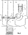
- the figure 2 illustrates an exemplary embodiment in which three sensors SAW 10 1, 10 2, 10 3 are arranged in the compartment M. A lower number (for example two SAW sensors) or higher of sensors can however be envisaged.
- SAW sensors 10 1 , 10 2 , 10 3 are located on engine parts which are generally mobile and whose physical and / or analog parameters must be monitored.
- the SAW sensors 10 1 , 10 2 , 10 3 are positioned at level of a cylinder C of a diesel engine.
- a first sensor 10 1 is positioned on the piston P, a second sensor 10 2 on the connecting rod B and a third sensor 10 3 on the crankshaft V.
- Each SAW sensor 10 1 , 10 2 , 10 3 comprises a "mobile" antenna - as arranged on a part of the engine that is mobile - which is its own. These "mobile" antennas are configured to receive the signals transmitted by the antenna 20a and to emit, in the direction of said antenna 20a, the reply signals.
- the SAW sensors 10 1 , 10 2 , 10 3 each have a distinct resonant frequency of their own.
- the unit 30 has incorporates a transmitter simultaneously sends multiple electromagnetic signals interrogation to the antenna 20a, each of said signals having a frequency close to the resonance frequency of the SAW sensors 10 1, 10 2, 10 March.
- the antenna 20 is thus configured to emit a plurality of loops of different frequencies (an SAW sensor).
- the received signals and then emitted by the antenna 20 is transmitted to the antennas "mobile" SAW sensors 10 1, 10 2, 10 3, and converted into surface acoustic waves that propagate on the surface of substrates used by said SAW sensors .
- the properties of these surface waves, and in particular their wavelength, are modified as a function of the physical and / or analog parameters (temperature, pressure, stress, deformation, position in space, etc.) of the parts on which are arranged SAW sensors 10 1, 10 2, 10 March. These parameters more particularly affect the resonance frequency of each SAW sensor 10 1 , 10 2 , 10 3 .
- the latter re-transmit to the antenna 20 has a response signal at a resonance frequency own carrying information related to the parameters to monitor.
- the response of SAW sensors 10 1 , 10 2 , 10 3 is a frequency variation depending on the parameters to be monitored, which is more advantageous than a principle based on the delay lines.
- the response signals received by the antenna 20a are then transferred to the unit 30 a that includes a suitable receiver configured to retrieve the information sought as a function of frequency actually received.
- the unit 30 may thus examine the various sensors SAW 10 1, 10 2, 10 3 per via the single antenna 20 a.
- the antenna 20 has uses ISM frequencies to communicate with the sensors 10 1, 10 2, 10 March.
- the ISM bands (for the acronym Industrial, Scientific and Medical) are frequency bands whose use for industrial, scientific, medical, domestic or similar applications is allowed without any request for authorization from the authorities [].
- the ISM frequency bands are defined in the EN 55011 standard and for the USA, by the publication FCC Part 18.
- the use of the ISM frequency bands allows a reading distance of up to 100 cm , depending on the positioning of the SAW sensors 10 1 , 10 2 , 10 3 in the motor and the geometry thereof.
- ISM frequencies or close to these frequencies, that is to say between 433 MHz and 445 MHz, allows better performance vis-à-vis the problems of reflections, diffractions and absorptions waves electromagnetic in the metallic environment of the crankcase.
- Other types of frequencies suitable to those skilled in the art could however be used, including ISM frequencies, or close to these frequencies, between 866 MHz and 890 MHz.
- ISM frequencies or close to these frequencies, between 866 MHz and 890 MHz.
- These higher ISM frequencies make it possible to reduce the size of the antennas, so that the monitoring system which is the subject of the invention can be installed in smaller motors.
- the antenna 20 may also use other frequencies very close to the ISM frequencies. Indeed, some SAW sensors may have frequencies slightly beyond the ISM bands (from 0.5 MHz to 10 MHz for example), because of a possible "Faraday cage" effect of the compartments M a , M b , M c . To communicate with sensors 10 1, 10 2, 10 3 which are associated to it, the antenna 20 may use, for example frequencies of between 423 MHz and 435 MHz which are ISM frequencies near low, or the frequency range 846 MHz and 870 MHz and are close to high ISM frequencies.
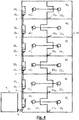
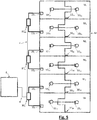
- the figures 3 , 4 and 5 illustrate examples of uses that can be made of the system which is the subject of the invention, with a view to measuring, for example, the temperature in the bearings and crank pinions in a diesel engine M, or Otto type if it is a gas engine. It is understood that other parameters such as pressure, stress, deformation or position in space can be monitored.
- the engine cylinders are arranged "in line” while on the figures 4 and 5 they are in a "Ve" configuration.
- Each antenna 20a, ..., 20f is connected, either alone or in pairs, to an electronic control unit 30 a, ..., f 30.
- motor M is compartmentalized.
- Each compartment M has , ..., M f comprises: an electronic control unit 30 a , ..., 30 f each associated with a single antenna 20 a , ..., 20 f , ( figures 3 and 4 ) or two ( figure 5 ), each of which antennas communicates with sensors SAW 10 1a , 10 2a , 10 3a , ..., 10f , 10f , 10f placed directly inside the compartments, on the parts of which physical parameters and / or analogs must be monitored.
- SAW temperature sensors 10 1a , ..., 10 1f on the pistons there are for example SAW temperature sensors 10 1a , ..., 10 1f on the pistons, SAW temperature sensors 2a , ..., 10 2f on the connecting rods and temperature sensors SAW 3a , ..., 3f on the bearings of the crankshaft.
- SAW sensors of temperature 10 1a , ..., 10 1f on the one hand and 10 2a , ..., 2 2f on the other hand, on the connecting rods of the pairs of cylinders which face each other are arranged, for example. and temperature SAW sensors 3a ,..., 3f on the bearings of the crankshaft.
- Each piece to be monitored is therefore provided with a sensor 10 1a , 10 2a , 10 3a , ..., 10f , 10f , 10f .
- the figures 3 , 4 and 5 illustrate an embodiment where three SAW sensors are arranged per engine compartment. A lower number (for example two SAW sensors) or higher of sensors can however be envisaged.
- the sensors 10 1a, 10 2a, 10 3a, ..., 10 1f, 2f 10 are arranged in the different compartments M, ..., M f so as sensors located in a compartment can not communicate with an antenna connected to a unit electronic control arranged in another compartment, and more specifically in a neighboring compartment.
- these sensors 10 1a , 10 2a , 10 3a , ..., 10f , 10f are arranged in the different compartments M a , ..., M f , according to their resonance frequency.
- each antenna 20a, ..., f 20 is installed within a compartment M, ..., M f.
- an antenna 20 a , ..., 20 f is installed inside each of the compartments M a , ..., M f .
- the units 30 a , ..., 30 f can each be installed outside or inside the compartments M a , ..., M f .
- Each antenna 20a, ..., 20f preferably interrogates only the SAW sensors 10 1a, 10 2a, 10 3a, ..., 10 1f, 2f 10 10 3f located in the engine compartment M, ..., M f .
- Each antenne20 a, ..., f 20 is inactive with respect to the neighboring compartments or different frequency because of those used in its own compartment. There is therefore no risk of interference with the other antennas installed in the other compartments and in particular the immediately adjacent compartments. More particularly, in the example illustrated on the figures 3 and 4 ,
- Each unit 30a, ... 30 f is connected to a single antenna 20 a, ..., f 20 of its own.
- Each unit (for example 30c ) simultaneously communicates, via its antenna (for example 20c ), with all the sensors (for example 10 1c , 10c , 10c ) which are located in its engine compartment (for example). example M c ).
- Each unit 30 ab, 30 cd, ef 30 is connected to two antennas 20 a -20 b, 20 c -20 d, 20 e -20 f, each of these antennas being installed inside a compartment M ..., M f dedicated to him.
- Each unit (for example, 30 ab ) communicates simultaneously, via the pair of antennas to which it is connected (for example 20 to -20 b ), with all the sensors (for example 10 1a , 10 2a , 10a) . 3a and 10b , 10b , 3b ) which are located in the motor compartments in which said antennas are integrated (for example M a and M b ).
- a special bandwidth is allocated to each of them which enables them, for example, to transmit three separate frequency loops within the same compartment M a ,..., M f equipped with three sensors SAW 10 1a , 10 2a , 10 3a , ..., 10 1f , 10 2f , 10 3f .
- the antenna for example 20 a , which is connected to the unit 30 a arranged in the compartment M a , emits frequencies in a predefined frequency band (for example 433 MHz to 439 MHz) which is different from the band of frequencies (for example 439 MHz to 445 MHz) in which emits the antenna 20 b connected to the unit 30 b disposed in another compartment M b .
- the unit 30 has is thus not able to communicate with the sensors 10 1b, 10 2b, 10 3b which are located in the adjacent compartment M b.
- the antennas for example 20 a and 20 b , which are connected in pairs to the unit ab , and which are respectively arranged in the compartment M a and in the compartment M b , each transmit frequencies in a frequency band predefined.
- the unit 30 ab control these antennas so that the frequency band in which the antenna 20 emits a is different from the frequency band in which the antenna 20 emits b.
- the unit 30 ab is thus able to communicate with sensors 10 1a, 10 2a, 10 3a on the one hand, and 10 1b, 10 2b, 10 3b on the other hand which are located respectively in the compartments M a and M b .
- the unit 30 ab but is not able to communicate with the sensors 10 1c, 10 2c, 10 3c which are located in the compartment M c.
- the antennas 20a, ..., 20f communicate with "n” SAW sensor compartment through "2xn” predetermined distinct frequencies.
- the units 30 a , ..., 30 f , 30 ab , ... ef are advantageously connected together by digital communication cables 4. And at least one of these units (e.g. 30 or 30 ef f) is connected to a supervisory equipment 6 so that all of said units to communicate therewith.
- the supervision equipment 6 is for example a computer on which all the information received by the different units 30 a , ..., 30 f , 30 ab , ... ef , are visualized and / or processed and / or analyzed.
- the system that is the subject of the invention comprises a single antenna per compartment and, on the other hand, the electronic control units are connected to each other and to the supervision equipment by a digital communication cable or a digital bus, said system reduces cabling constraints by optimizing the space dedicated to it, both inside and outside the engine.
- the sensors SAW 10 1a , 10 2a , 10 3a , ..., 10f , 10f , 10f , arranged in the same compartment can emit frequencies in a frequency band different from those emitted by the acoustic wave sensors of surface located in another nearby compartment. This avoids any harmful interference between the signals emitted by SAW sensors immediately adjacent compartments, and therefore physically close.
- a specific bandwidth can be allocated to each of the SAW sensors 10 1a, 10 2a, 10 3a, ..., 10 1f, 2f 10 10 3f, which allows them, for example, broadcasting in return to each of the antennas 20 a ,..., 20 f three distinct narrow strips inside the same compartment M a , ...., M f , equipped with three SAW sensors.
- the bandwidth allocated to each of the SAW sensors is preferably narrow, for example defined on an interval (or increment) of 2 MHz.
- the sensors 10 1a, 10 2a, 10 3a communicating with the antenna 20 is connected to the unit 30 a, and which are disposed in the compartment M, in turn issue frequencies in predefined frequency bands respectively for example 433 MHz at 435 MHz, 435 MHz at 437 MHz, and 437 MHz at 439 MHz. These frequency bands are different from the frequency bands (for example 439 MHz to 441 MHz, 441 MHz to 443 MHz, and 443 MHz to 445 MHz) in which the sensors 1b , 10 2b , 3b transmit back to the receiver .
- antenna 20b connected to the unit 30b , and arranged in the neighboring compartment M b .
- the unit 30 has is thus not disturbed by the sensors 10 1b, 10 2b, 10 3b which are located in the compartment M b.
- an antenna 20a, ..., 20f that is installed in a compartment M, ..., M f, emit frequencies within a predetermined frequency band which is different from the frequency band in which the antenna emits in another compartment.
- all antennas 20a, ..., 20f may each transmit simultaneously several discrete frequencies covering all the frequencies of all the resonance sensors 10 1a, 10 2a, 10 3a, ..., 10 1f, 2f , including, but not limited to, frequencies close to the resonant frequencies of the sensors that are located in the compartment dedicated to them.
- All antennas 20 a, ..., f 20 are thus identical and dimensioned to be able to emit the same frequency spectrum broadband.
Landscapes
- Physics & Mathematics (AREA)
- Engineering & Computer Science (AREA)
- General Physics & Mathematics (AREA)
- Computer Networks & Wireless Communication (AREA)
- Chemical & Material Sciences (AREA)
- Health & Medical Sciences (AREA)
- Life Sciences & Earth Sciences (AREA)
- Analytical Chemistry (AREA)
- Biochemistry (AREA)
- General Health & Medical Sciences (AREA)
- Immunology (AREA)
- Pathology (AREA)
- Acoustics & Sound (AREA)
- Combustion & Propulsion (AREA)
- Arrangements For Transmission Of Measured Signals (AREA)
Priority Applications (1)
| Application Number | Priority Date | Filing Date | Title |
|---|---|---|---|
| PL13805426T PL2907321T3 (pl) | 2012-10-10 | 2013-10-09 | System przeznaczony do monitorowania parametrów fizycznych i/lub analogowych elementów silnika |
Applications Claiming Priority (2)
| Application Number | Priority Date | Filing Date | Title |
|---|---|---|---|
| FR1202706A FR2996599B1 (fr) | 2012-10-10 | 2012-10-10 | Systeme dedie a la surveillance des parametres physiques et/ou analogiques des pieces d'un moteur |
| PCT/FR2013/052409 WO2014057219A1 (fr) | 2012-10-10 | 2013-10-09 | Systeme dedie a la surveillance des parametres physiques et/ou analogiques des pieces d'un moteur |
Publications (2)
| Publication Number | Publication Date |
|---|---|
| EP2907321A1 EP2907321A1 (fr) | 2015-08-19 |
| EP2907321B1 true EP2907321B1 (fr) | 2016-12-07 |
Family
ID=47424954
Family Applications (1)
| Application Number | Title | Priority Date | Filing Date |
|---|---|---|---|
| EP13805426.7A Not-in-force EP2907321B1 (fr) | 2012-10-10 | 2013-10-09 | Système dedié à la surveillance des paramètres physiques et/ou analogiques des pieces d'un moteur |
Country Status (7)
| Country | Link |
|---|---|
| US (1) | US9766161B2 (pl) |
| EP (1) | EP2907321B1 (pl) |
| CN (1) | CN104685901B (pl) |
| DK (1) | DK2907321T3 (pl) |
| FR (1) | FR2996599B1 (pl) |
| PL (1) | PL2907321T3 (pl) |
| WO (1) | WO2014057219A1 (pl) |
Families Citing this family (6)
| Publication number | Priority date | Publication date | Assignee | Title |
|---|---|---|---|---|
| CN108476565B (zh) * | 2015-12-18 | 2021-08-13 | 昕诺飞控股有限公司 | 照明条 |
| CN105806625A (zh) * | 2016-03-21 | 2016-07-27 | 中北大学 | 发动机内不同核心部件的联合测试方法和装置 |
| US10838053B2 (en) | 2018-07-03 | 2020-11-17 | General Electric Company | System and method of measuring blade clearance in a turbine engine |
| CN111121988B (zh) * | 2019-12-30 | 2021-05-25 | 中国船舶重工集团公司第七一一研究所 | 适用于v型发动机连杆轴瓦的测温装置及测温方法 |
| CN113027608B (zh) * | 2021-04-06 | 2022-03-01 | 华中科技大学 | 一种内燃机活塞顶面瞬态温度遥测系统及其安装方法 |
| CN115265985A (zh) * | 2022-08-29 | 2022-11-01 | 绵阳新晨动力机械有限公司 | 一种发动机台架共振测试方法、系统、设备及介质 |
Family Cites Families (8)
| Publication number | Priority date | Publication date | Assignee | Title |
|---|---|---|---|---|
| EP0051035A1 (fr) | 1980-08-22 | 1982-05-05 | Controle Mesure Regulation - Cmr (S.A.) | Dispositif de contrôle de température (ou d'autre paramètre physique binaire) de pièces à mouvement périodique |
| DE59700618D1 (de) | 1996-01-31 | 1999-12-02 | Siemens Ag | Gekapselte anlage |
| NO322272B1 (no) * | 1999-03-26 | 2006-09-04 | Kongsberg Maritime As | Sensor og system for overvaking av temperatur inne i vanskelig tilgjengelige, bevegelige deler |
| US7911324B2 (en) * | 2001-02-16 | 2011-03-22 | Automotive Technologies International, Inc. | Method and system for obtaining information about RFID-equipped objects |
| DE10325667A1 (de) * | 2003-06-06 | 2005-03-03 | Fag Kugelfischer Ag & Co. Ohg | Messsystem mit wenigstens zwei SAW-oder BAW-Sensoren und Verfahren zum Betreiben desselben |
| US7089099B2 (en) * | 2004-07-30 | 2006-08-08 | Automotive Technologies International, Inc. | Sensor assemblies |
| CN103038072B (zh) * | 2010-04-09 | 2016-08-10 | 倍耐力轮胎股份公司 | 轮胎传感器装置 |
| EP2422900A1 (en) * | 2010-08-26 | 2012-02-29 | SMS Concast AG | Arrangement for measuring physical parameters in continuous casting moulds |
-
2012
- 2012-10-10 FR FR1202706A patent/FR2996599B1/fr not_active Expired - Fee Related
-
2013
- 2013-10-09 DK DK13805426.7T patent/DK2907321T3/en active
- 2013-10-09 US US14/434,432 patent/US9766161B2/en not_active Expired - Fee Related
- 2013-10-09 EP EP13805426.7A patent/EP2907321B1/fr not_active Not-in-force
- 2013-10-09 PL PL13805426T patent/PL2907321T3/pl unknown
- 2013-10-09 WO PCT/FR2013/052409 patent/WO2014057219A1/fr not_active Ceased
- 2013-10-09 CN CN201380051327.5A patent/CN104685901B/zh not_active Expired - Fee Related
Also Published As
| Publication number | Publication date |
|---|---|
| EP2907321A1 (fr) | 2015-08-19 |
| DK2907321T3 (en) | 2017-03-13 |
| FR2996599A1 (fr) | 2014-04-11 |
| CN104685901B (zh) | 2019-01-01 |
| US20150241305A1 (en) | 2015-08-27 |
| FR2996599B1 (fr) | 2018-08-10 |
| PL2907321T3 (pl) | 2017-07-31 |
| CN104685901A (zh) | 2015-06-03 |
| WO2014057219A1 (fr) | 2014-04-17 |
| US9766161B2 (en) | 2017-09-19 |
Similar Documents
| Publication | Publication Date | Title |
|---|---|---|
| EP2907321B1 (fr) | Système dedié à la surveillance des paramètres physiques et/ou analogiques des pieces d'un moteur | |
| EP2799899B1 (fr) | Système d'interrogation d'un capteur passif interrogeable à distance intégré dans une cavité métallique à bilan de liaison amélioré et procédé d'interrogation | |
| EP1484616A1 (fr) | Méthode de détection de décharges partielles et système de diagnostic pour appareil électrique | |
| WO2009034039A1 (fr) | Télémètre relatif hyperfréquence de haute précision | |
| CA2840848C (fr) | Dispositif pour detecter des objets tels que des mines | |
| EP2769237B1 (fr) | Procédé d'interrogation rapide d'un capteur passif, notamment du type à ondes acoustiques de surface, et système de mesure de la fréquence propre d'un tel capteur | |
| CA1287190C (fr) | Procede de correction d'un dispositif a ondes de surface, notamment pour un filtre dispersif | |
| FR2971584A1 (fr) | Capteur de temperature ou de temperature et de pression sans fil, comportant des resonateurs a ondes acoustiques a electrodes en alliage | |
| WO2008037705A1 (fr) | Dispositif micro-onde de controle d'un materiau | |
| FR2997508A1 (fr) | Harnais et cable comportant une pluralite de capteurs elementaires et procede de surveillance d'un cable et d'un harnais | |
| WO1993016450A1 (fr) | Procede et systeme de transmission a une unite de commande de donnees de temperature et d'hygrometrie | |
| FR2879301A1 (fr) | Transpondeurs a ondes acoustiques de surface | |
| EP3791366B1 (fr) | Système d'échange de données dans un aéronef | |
| EP3701572B1 (fr) | Structure alveolaire comprenant un dispositif de controle d'integrite et procede de contrôle d'une telle structure | |
| FR2943140A1 (fr) | Telemetre absolu hyperfrequence de haute precision a mesure par reflexion | |
| FR2943139A1 (fr) | Telemetre absolu hyperfrequence de haute precision a mesure par transmission | |
| FR2906630A1 (fr) | Dispositif d'interrogation d'un capteur passif de type a ondes acoustiques de surface. | |
| EP3400654B1 (fr) | Dispositif utilisant une antenne électriquement petite pour obtenir au moins une information sur un objet présent dans le champ proche de ladite antenne | |
| FR2880115A1 (fr) | Procede et installation de mesure et controle de temperature d'un corps par radiometrie micro-onde en environnement extreme prenant en compte les caracteristiques de l'organe de liaison reliant le capteur au radiometre | |
| WO2022008354A1 (fr) | Système de communication pour aéronef | |
| Larsen et al. | Sensing challenges for mechanical aerospace prognostic health monitoring | |
| EP4500933A1 (fr) | Systeme d'emission et reception intelligent integre et compact | |
| FR3113316A1 (fr) | Capteur à ondes acoustiques et interrogation de celui-ci | |
| FR2880122A1 (fr) | Procede et installation de detection de la presence d'un corps | |
| FR3103893A1 (fr) | Système et procédé d’identification de paramètres d’un capteur fixé sur un carter |
Legal Events
| Date | Code | Title | Description |
|---|---|---|---|
| PUAI | Public reference made under article 153(3) epc to a published international application that has entered the european phase |
Free format text: ORIGINAL CODE: 0009012 |
|
| 17P | Request for examination filed |
Effective date: 20150408 |
|
| AK | Designated contracting states |
Kind code of ref document: A1 Designated state(s): AL AT BE BG CH CY CZ DE DK EE ES FI FR GB GR HR HU IE IS IT LI LT LU LV MC MK MT NL NO PL PT RO RS SE SI SK SM TR |
|
| AX | Request for extension of the european patent |
Extension state: BA ME |
|
| DAX | Request for extension of the european patent (deleted) | ||
| GRAP | Despatch of communication of intention to grant a patent |
Free format text: ORIGINAL CODE: EPIDOSNIGR1 |
|
| RIC1 | Information provided on ipc code assigned before grant |
Ipc: G01N 29/24 20060101ALI20160518BHEP Ipc: H04Q 9/00 20060101AFI20160518BHEP Ipc: G01K 11/26 20060101ALI20160518BHEP Ipc: G01M 15/05 20060101ALI20160518BHEP |
|
| INTG | Intention to grant announced |
Effective date: 20160602 |
|
| GRAS | Grant fee paid |
Free format text: ORIGINAL CODE: EPIDOSNIGR3 |
|
| GRAA | (expected) grant |
Free format text: ORIGINAL CODE: 0009210 |
|
| AK | Designated contracting states |
Kind code of ref document: B1 Designated state(s): AL AT BE BG CH CY CZ DE DK EE ES FI FR GB GR HR HU IE IS IT LI LT LU LV MC MK MT NL NO PL PT RO RS SE SI SK SM TR |
|
| REG | Reference to a national code |
Ref country code: GB Ref legal event code: FG4D Free format text: NOT ENGLISH |
|
| REG | Reference to a national code |
Ref country code: CH Ref legal event code: EP Ref country code: AT Ref legal event code: REF Ref document number: 852632 Country of ref document: AT Kind code of ref document: T Effective date: 20161215 |
|
| REG | Reference to a national code |
Ref country code: IE Ref legal event code: FG4D Free format text: LANGUAGE OF EP DOCUMENT: FRENCH |
|
| REG | Reference to a national code |
Ref country code: DE Ref legal event code: R096 Ref document number: 602013015154 Country of ref document: DE |
|
| PG25 | Lapsed in a contracting state [announced via postgrant information from national office to epo] |
Ref country code: LV Free format text: LAPSE BECAUSE OF FAILURE TO SUBMIT A TRANSLATION OF THE DESCRIPTION OR TO PAY THE FEE WITHIN THE PRESCRIBED TIME-LIMIT Effective date: 20161207 |
|
| REG | Reference to a national code |
Ref country code: DK Ref legal event code: T3 Effective date: 20170309 |
|
| REG | Reference to a national code |
Ref country code: NL Ref legal event code: FP |
|
| REG | Reference to a national code |
Ref country code: LT Ref legal event code: MG4D |
|
| PG25 | Lapsed in a contracting state [announced via postgrant information from national office to epo] |
Ref country code: GR Free format text: LAPSE BECAUSE OF FAILURE TO SUBMIT A TRANSLATION OF THE DESCRIPTION OR TO PAY THE FEE WITHIN THE PRESCRIBED TIME-LIMIT Effective date: 20170308 Ref country code: LT Free format text: LAPSE BECAUSE OF FAILURE TO SUBMIT A TRANSLATION OF THE DESCRIPTION OR TO PAY THE FEE WITHIN THE PRESCRIBED TIME-LIMIT Effective date: 20161207 Ref country code: SE Free format text: LAPSE BECAUSE OF FAILURE TO SUBMIT A TRANSLATION OF THE DESCRIPTION OR TO PAY THE FEE WITHIN THE PRESCRIBED TIME-LIMIT Effective date: 20161207 |
|
| REG | Reference to a national code |
Ref country code: NO Ref legal event code: T2 Effective date: 20161207 |
|
| PG25 | Lapsed in a contracting state [announced via postgrant information from national office to epo] |
Ref country code: RS Free format text: LAPSE BECAUSE OF FAILURE TO SUBMIT A TRANSLATION OF THE DESCRIPTION OR TO PAY THE FEE WITHIN THE PRESCRIBED TIME-LIMIT Effective date: 20161207 Ref country code: ES Free format text: LAPSE BECAUSE OF FAILURE TO SUBMIT A TRANSLATION OF THE DESCRIPTION OR TO PAY THE FEE WITHIN THE PRESCRIBED TIME-LIMIT Effective date: 20161207 Ref country code: HR Free format text: LAPSE BECAUSE OF FAILURE TO SUBMIT A TRANSLATION OF THE DESCRIPTION OR TO PAY THE FEE WITHIN THE PRESCRIBED TIME-LIMIT Effective date: 20161207 |
|
| PG25 | Lapsed in a contracting state [announced via postgrant information from national office to epo] |
Ref country code: SK Free format text: LAPSE BECAUSE OF FAILURE TO SUBMIT A TRANSLATION OF THE DESCRIPTION OR TO PAY THE FEE WITHIN THE PRESCRIBED TIME-LIMIT Effective date: 20161207 Ref country code: RO Free format text: LAPSE BECAUSE OF FAILURE TO SUBMIT A TRANSLATION OF THE DESCRIPTION OR TO PAY THE FEE WITHIN THE PRESCRIBED TIME-LIMIT Effective date: 20161207 Ref country code: IS Free format text: LAPSE BECAUSE OF FAILURE TO SUBMIT A TRANSLATION OF THE DESCRIPTION OR TO PAY THE FEE WITHIN THE PRESCRIBED TIME-LIMIT Effective date: 20170407 Ref country code: EE Free format text: LAPSE BECAUSE OF FAILURE TO SUBMIT A TRANSLATION OF THE DESCRIPTION OR TO PAY THE FEE WITHIN THE PRESCRIBED TIME-LIMIT Effective date: 20161207 |
|
| PG25 | Lapsed in a contracting state [announced via postgrant information from national office to epo] |
Ref country code: PT Free format text: LAPSE BECAUSE OF FAILURE TO SUBMIT A TRANSLATION OF THE DESCRIPTION OR TO PAY THE FEE WITHIN THE PRESCRIBED TIME-LIMIT Effective date: 20170407 Ref country code: SM Free format text: LAPSE BECAUSE OF FAILURE TO SUBMIT A TRANSLATION OF THE DESCRIPTION OR TO PAY THE FEE WITHIN THE PRESCRIBED TIME-LIMIT Effective date: 20161207 Ref country code: BG Free format text: LAPSE BECAUSE OF FAILURE TO SUBMIT A TRANSLATION OF THE DESCRIPTION OR TO PAY THE FEE WITHIN THE PRESCRIBED TIME-LIMIT Effective date: 20170307 |
|
| REG | Reference to a national code |
Ref country code: DE Ref legal event code: R097 Ref document number: 602013015154 Country of ref document: DE |
|
| PLBE | No opposition filed within time limit |
Free format text: ORIGINAL CODE: 0009261 |
|
| STAA | Information on the status of an ep patent application or granted ep patent |
Free format text: STATUS: NO OPPOSITION FILED WITHIN TIME LIMIT |
|
| REG | Reference to a national code |
Ref country code: FR Ref legal event code: PLFP Year of fee payment: 5 |
|
| 26N | No opposition filed |
Effective date: 20170908 |
|
| PG25 | Lapsed in a contracting state [announced via postgrant information from national office to epo] |
Ref country code: SI Free format text: LAPSE BECAUSE OF FAILURE TO SUBMIT A TRANSLATION OF THE DESCRIPTION OR TO PAY THE FEE WITHIN THE PRESCRIBED TIME-LIMIT Effective date: 20161207 |
|
| PG25 | Lapsed in a contracting state [announced via postgrant information from national office to epo] |
Ref country code: MC Free format text: LAPSE BECAUSE OF FAILURE TO SUBMIT A TRANSLATION OF THE DESCRIPTION OR TO PAY THE FEE WITHIN THE PRESCRIBED TIME-LIMIT Effective date: 20161207 |
|
| REG | Reference to a national code |
Ref country code: IE Ref legal event code: MM4A |
|
| PG25 | Lapsed in a contracting state [announced via postgrant information from national office to epo] |
Ref country code: LU Free format text: LAPSE BECAUSE OF NON-PAYMENT OF DUE FEES Effective date: 20171009 |
|
| PG25 | Lapsed in a contracting state [announced via postgrant information from national office to epo] |
Ref country code: MT Free format text: LAPSE BECAUSE OF FAILURE TO SUBMIT A TRANSLATION OF THE DESCRIPTION OR TO PAY THE FEE WITHIN THE PRESCRIBED TIME-LIMIT Effective date: 20161207 |
|
| PG25 | Lapsed in a contracting state [announced via postgrant information from national office to epo] |
Ref country code: IE Free format text: LAPSE BECAUSE OF NON-PAYMENT OF DUE FEES Effective date: 20171009 |
|
| REG | Reference to a national code |
Ref country code: FR Ref legal event code: PLFP Year of fee payment: 6 |
|
| PG25 | Lapsed in a contracting state [announced via postgrant information from national office to epo] |
Ref country code: HU Free format text: LAPSE BECAUSE OF FAILURE TO SUBMIT A TRANSLATION OF THE DESCRIPTION OR TO PAY THE FEE WITHIN THE PRESCRIBED TIME-LIMIT; INVALID AB INITIO Effective date: 20131009 |
|
| PG25 | Lapsed in a contracting state [announced via postgrant information from national office to epo] |
Ref country code: CY Free format text: LAPSE BECAUSE OF FAILURE TO SUBMIT A TRANSLATION OF THE DESCRIPTION OR TO PAY THE FEE WITHIN THE PRESCRIBED TIME-LIMIT Effective date: 20161207 |
|
| PG25 | Lapsed in a contracting state [announced via postgrant information from national office to epo] |
Ref country code: MK Free format text: LAPSE BECAUSE OF FAILURE TO SUBMIT A TRANSLATION OF THE DESCRIPTION OR TO PAY THE FEE WITHIN THE PRESCRIBED TIME-LIMIT Effective date: 20161207 |
|
| REG | Reference to a national code |
Ref country code: AT Ref legal event code: UEP Ref document number: 852632 Country of ref document: AT Kind code of ref document: T Effective date: 20161207 |
|
| PG25 | Lapsed in a contracting state [announced via postgrant information from national office to epo] |
Ref country code: AL Free format text: LAPSE BECAUSE OF FAILURE TO SUBMIT A TRANSLATION OF THE DESCRIPTION OR TO PAY THE FEE WITHIN THE PRESCRIBED TIME-LIMIT Effective date: 20161207 |
|
| PGFP | Annual fee paid to national office [announced via postgrant information from national office to epo] |
Ref country code: TR Payment date: 20200930 Year of fee payment: 8 Ref country code: CZ Payment date: 20200929 Year of fee payment: 8 |
|
| PGFP | Annual fee paid to national office [announced via postgrant information from national office to epo] |
Ref country code: NL Payment date: 20201014 Year of fee payment: 8 |
|
| PGFP | Annual fee paid to national office [announced via postgrant information from national office to epo] |
Ref country code: GB Payment date: 20201118 Year of fee payment: 8 Ref country code: AT Payment date: 20201015 Year of fee payment: 8 Ref country code: CH Payment date: 20201117 Year of fee payment: 8 Ref country code: FR Payment date: 20201030 Year of fee payment: 8 Ref country code: DE Payment date: 20201109 Year of fee payment: 8 Ref country code: DK Payment date: 20201030 Year of fee payment: 8 Ref country code: FI Payment date: 20201016 Year of fee payment: 8 Ref country code: IT Payment date: 20201015 Year of fee payment: 8 Ref country code: NO Payment date: 20201021 Year of fee payment: 8 |
|
| PGFP | Annual fee paid to national office [announced via postgrant information from national office to epo] |
Ref country code: BE Payment date: 20201026 Year of fee payment: 8 Ref country code: PL Payment date: 20201015 Year of fee payment: 8 |
|
| REG | Reference to a national code |
Ref country code: DE Ref legal event code: R119 Ref document number: 602013015154 Country of ref document: DE |
|
| REG | Reference to a national code |
Ref country code: NO Ref legal event code: MMEP Ref country code: DK Ref legal event code: EBP Effective date: 20211031 |
|
| REG | Reference to a national code |
Ref country code: FI Ref legal event code: MAE |
|
| REG | Reference to a national code |
Ref country code: CH Ref legal event code: PL |
|
| PG25 | Lapsed in a contracting state [announced via postgrant information from national office to epo] |
Ref country code: CZ Free format text: LAPSE BECAUSE OF NON-PAYMENT OF DUE FEES Effective date: 20211009 |
|
| REG | Reference to a national code |
Ref country code: NL Ref legal event code: MM Effective date: 20211101 |
|
| REG | Reference to a national code |
Ref country code: AT Ref legal event code: MM01 Ref document number: 852632 Country of ref document: AT Kind code of ref document: T Effective date: 20211009 |
|
| REG | Reference to a national code |
Ref country code: BE Ref legal event code: MM Effective date: 20211031 |
|
| GBPC | Gb: european patent ceased through non-payment of renewal fee |
Effective date: 20211009 |
|
| PG25 | Lapsed in a contracting state [announced via postgrant information from national office to epo] |
Ref country code: NO Free format text: LAPSE BECAUSE OF NON-PAYMENT OF DUE FEES Effective date: 20211031 Ref country code: NL Free format text: LAPSE BECAUSE OF NON-PAYMENT OF DUE FEES Effective date: 20211101 Ref country code: GB Free format text: LAPSE BECAUSE OF NON-PAYMENT OF DUE FEES Effective date: 20211009 Ref country code: DE Free format text: LAPSE BECAUSE OF NON-PAYMENT OF DUE FEES Effective date: 20220503 Ref country code: BE Free format text: LAPSE BECAUSE OF NON-PAYMENT OF DUE FEES Effective date: 20211031 |
|
| PG25 | Lapsed in a contracting state [announced via postgrant information from national office to epo] |
Ref country code: LI Free format text: LAPSE BECAUSE OF NON-PAYMENT OF DUE FEES Effective date: 20211031 Ref country code: FI Free format text: LAPSE BECAUSE OF NON-PAYMENT OF DUE FEES Effective date: 20211009 Ref country code: CH Free format text: LAPSE BECAUSE OF NON-PAYMENT OF DUE FEES Effective date: 20211031 Ref country code: AT Free format text: LAPSE BECAUSE OF NON-PAYMENT OF DUE FEES Effective date: 20211009 |
|
| PG25 | Lapsed in a contracting state [announced via postgrant information from national office to epo] |
Ref country code: FR Free format text: LAPSE BECAUSE OF NON-PAYMENT OF DUE FEES Effective date: 20211031 |
|
| PG25 | Lapsed in a contracting state [announced via postgrant information from national office to epo] |
Ref country code: IT Free format text: LAPSE BECAUSE OF NON-PAYMENT OF DUE FEES Effective date: 20211009 Ref country code: DK Free format text: LAPSE BECAUSE OF NON-PAYMENT OF DUE FEES Effective date: 20211031 |
|
| PG25 | Lapsed in a contracting state [announced via postgrant information from national office to epo] |
Ref country code: PL Free format text: LAPSE BECAUSE OF NON-PAYMENT OF DUE FEES Effective date: 20211009 |
|
| PG25 | Lapsed in a contracting state [announced via postgrant information from national office to epo] |
Ref country code: TR Free format text: LAPSE BECAUSE OF NON-PAYMENT OF DUE FEES Effective date: 20211009 |