EP2907321B1 - System dedicated to monitoring the physical and/or analogue parameters of the parts of an engine - Google Patents
System dedicated to monitoring the physical and/or analogue parameters of the parts of an engine Download PDFInfo
- Publication number
- EP2907321B1 EP2907321B1 EP13805426.7A EP13805426A EP2907321B1 EP 2907321 B1 EP2907321 B1 EP 2907321B1 EP 13805426 A EP13805426 A EP 13805426A EP 2907321 B1 EP2907321 B1 EP 2907321B1
- Authority
- EP
- European Patent Office
- Prior art keywords
- antenna
- sensors
- compartment
- frequencies
- mhz
- Prior art date
- Legal status (The legal status is an assumption and is not a legal conclusion. Google has not performed a legal analysis and makes no representation as to the accuracy of the status listed.)
- Active
Links
Images


Classifications
-
- G—PHYSICS
- G01—MEASURING; TESTING
- G01M—TESTING STATIC OR DYNAMIC BALANCE OF MACHINES OR STRUCTURES; TESTING OF STRUCTURES OR APPARATUS, NOT OTHERWISE PROVIDED FOR
- G01M15/00—Testing of engines
- G01M15/04—Testing internal-combustion engines
- G01M15/05—Testing internal-combustion engines by combined monitoring of two or more different engine parameters
-
- G—PHYSICS
- G01—MEASURING; TESTING
- G01K—MEASURING TEMPERATURE; MEASURING QUANTITY OF HEAT; THERMALLY-SENSITIVE ELEMENTS NOT OTHERWISE PROVIDED FOR
- G01K11/00—Measuring temperature based upon physical or chemical changes not covered by groups G01K3/00, G01K5/00, G01K7/00 or G01K9/00
- G01K11/22—Measuring temperature based upon physical or chemical changes not covered by groups G01K3/00, G01K5/00, G01K7/00 or G01K9/00 using measurement of acoustic effects
- G01K11/26—Measuring temperature based upon physical or chemical changes not covered by groups G01K3/00, G01K5/00, G01K7/00 or G01K9/00 using measurement of acoustic effects of resonant frequencies
- G01K11/265—Measuring temperature based upon physical or chemical changes not covered by groups G01K3/00, G01K5/00, G01K7/00 or G01K9/00 using measurement of acoustic effects of resonant frequencies using surface acoustic wave [SAW]
-
- G—PHYSICS
- G01—MEASURING; TESTING
- G01N—INVESTIGATING OR ANALYSING MATERIALS BY DETERMINING THEIR CHEMICAL OR PHYSICAL PROPERTIES
- G01N29/00—Investigating or analysing materials by the use of ultrasonic, sonic or infrasonic waves; Visualisation of the interior of objects by transmitting ultrasonic or sonic waves through the object
- G01N29/22—Details, e.g. general constructional or apparatus details
- G01N29/24—Probes
- G01N29/2481—Wireless probes, e.g. with transponders or radio links
-
- H—ELECTRICITY
- H04—ELECTRIC COMMUNICATION TECHNIQUE
- H04Q—SELECTING
- H04Q9/00—Arrangements in telecontrol or telemetry systems for selectively calling a substation from a main station, in which substation desired apparatus is selected for applying a control signal thereto or for obtaining measured values therefrom
-
- G—PHYSICS
- G01—MEASURING; TESTING
- G01K—MEASURING TEMPERATURE; MEASURING QUANTITY OF HEAT; THERMALLY-SENSITIVE ELEMENTS NOT OTHERWISE PROVIDED FOR
- G01K2205/00—Application of thermometers in motors, e.g. of a vehicle
Definitions
- the subject of the invention is a system dedicated to monitoring the physical and / or analog parameters of the parts of an engine.
- the invention relates to techniques for measuring and controlling various parameters on moving and / or inaccessible mechanical parts of an engine, intended in particular for the monitoring and safety of reciprocating internal combustion engines.
- EP 0.051.035 a device for controlling the temperature of the internal moving parts of an engine via a transceiver formed of two fixed coils.
- This transceiver transmits a signal carried by a resonant magnetic circuit at a determined frequency.
- This signal is detected by a sensor (formed by a moving coil) placed on a moving part, and connected to a thermistor that reacts to the temperature of the part, affect the sensitivity of the sensor, which then detects more or less the signal sent to it by the transceiver.
- the resonant signal is measured by the transceiver and is interpreted by an electronic device in temperature unit.
- the thermistor that defines the response of the sensor according to non-linear variations, which is inconvenient since according to the quality and accuracy of this element, the measurements can be falsified over large ranges of variation.
- the receiver transmitter generates a magnetic field through which the waves circulate.
- this magnetic field is not fully detected by the sensor, which results in the loss of part of the waves emitted and received by the transmitter / receiver.
- the accuracy of the measurement therefore depends on the quality of the system coil and the tedious calibrations to be performed for each sensor at the factory.
- the maximum reading distance separating the transmitter / receiver from the sensor is only of the order of 2 mm, which is quite low and can pose a problem for some moving parts, for example compared to the operating sets which can be of the same order of magnitude.
- SAW Surface Acoustic Wave
- a single electronic control unit 3 interrogates, via antennas 2, several SAW sensors 1 placed in each engine compartment, on the parts whose temperature must be measured.
- the information is communicated by the electronic control unit 3 to a supervision equipment 6 via a digital bus 5.
- This system has several disadvantages.
- this method is restrictive since it considerably increases the waiting time between each interrogation operation of the sensors 1.
- the single control unit 3 successively interrogates the sensors 1 by sending everything from first a signal via coaxial cables 4 connected to the antennas 2. These communicate with the SAW sensors 1. The response signal follows the reverse path.
- Receiving and processing the multiple signals received by the electronic control unit 3 increases the duration of the analysis.
- the metallic environment of the motor has the effect of leading to the loss of some of these signals and thus reduce the efficiency of the measurements made.
- Each communication between the antenna 2 and its SAW sensor 1 is effected by means of a single frequency for all the antennas 2. The use of this single frequency therefore imposes sequential interrogations of each sensor 1 to avoid interference between the responses of nearby sensors.
- Patent documents EP 2,422,900 (SMS CONCAST) and US 6,239,723 (SIEMENS) disclose systems for interrogating SAW sensors, respectively disposed in an ingot mold and in an electrical cabinet. These SAW sensors are placed on fixed parts, non-moving, easy to access, and in a much less restrictive environment than that of an engine.
- the main objective of the invention is to overcome the aforementioned drawbacks, and in particular to improve the measurement capabilities of moving parts that are difficult to access.
- Another object of the invention is to obtain a faster and more accurate analysis than those obtained with the systems of the prior art, avoiding the constraints imposed by the multiplexing method taught in the patent document.
- the invention also aims to provide a monitoring system to reduce space constraints and cabling by compared to those imposed in the system of the patent document WO 00/62029 (SENSIT) supra.
- the invention also aims to improve performance vis-à-vis the problems related to the metal environment of the engine housing.
- the solution proposed by the invention is a system for monitoring physical and / or analog parameters relating to parts of an engine, said system comprising at least one electronic control unit configured to interrogate, via at least one an antenna, a surface acoustic wave sensor (or SAW sensor) located on one of said parts.
- at least one electronic control unit configured to interrogate, via at least one an antenna, a surface acoustic wave sensor (or SAW sensor) located on one of said parts.
- the system comprises at least one electronic control unit 30a, 30b, 30c.
- Each of these units integrates one or more processors or microprocessors as well as a memory zone in which are stored computer programs comprising instructions which, when executed by said processor or microprocessor, make it possible to carry out the functionalities and steps described above. after, and in particular the acquisition of the various data output from the various sensors and / or transmission of control information to the antenna 20 a, 20 b, 20 c to which it is connected.
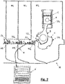
- the motor M has several compartments M a , M b , M c .
- the arrangement of the system in the compartment M will now be felicitL'reci control electronics 30 a is connected to a single antenna 20 a.
- the latter can be directly integrated in the housing of the unit 30 a or be remote, in which case the communication is performed via a wired or wireless connection using a communication protocol known to those skilled in the art ( radio wave, wifi, Bluetooth, ).
- the antenna 20 is used is for example an antenna "quarter-wave” or PIFA (Planar acronym for Inverted-F Antenna).
- each antenna is typically associated with a single SAW sensor
- the invention now proposes to communicate with the antenna 20 has several SAW sensors 10 1, 10 2, 10 March.
- the figure 2 illustrates an exemplary embodiment in which three sensors SAW 10 1, 10 2, 10 3 are arranged in the compartment M. A lower number (for example two SAW sensors) or higher of sensors can however be envisaged.
- SAW sensors 10 1 , 10 2 , 10 3 are located on engine parts which are generally mobile and whose physical and / or analog parameters must be monitored.
- the SAW sensors 10 1 , 10 2 , 10 3 are positioned at level of a cylinder C of a diesel engine.
- a first sensor 10 1 is positioned on the piston P, a second sensor 10 2 on the connecting rod B and a third sensor 10 3 on the crankshaft V.
- Each SAW sensor 10 1 , 10 2 , 10 3 comprises a "mobile" antenna - as arranged on a part of the engine that is mobile - which is its own. These "mobile" antennas are configured to receive the signals transmitted by the antenna 20a and to emit, in the direction of said antenna 20a, the reply signals.
- the SAW sensors 10 1 , 10 2 , 10 3 each have a distinct resonant frequency of their own.
- the unit 30 has incorporates a transmitter simultaneously sends multiple electromagnetic signals interrogation to the antenna 20a, each of said signals having a frequency close to the resonance frequency of the SAW sensors 10 1, 10 2, 10 March.
- the antenna 20 is thus configured to emit a plurality of loops of different frequencies (an SAW sensor).
- the received signals and then emitted by the antenna 20 is transmitted to the antennas "mobile" SAW sensors 10 1, 10 2, 10 3, and converted into surface acoustic waves that propagate on the surface of substrates used by said SAW sensors .
- the properties of these surface waves, and in particular their wavelength, are modified as a function of the physical and / or analog parameters (temperature, pressure, stress, deformation, position in space, etc.) of the parts on which are arranged SAW sensors 10 1, 10 2, 10 March. These parameters more particularly affect the resonance frequency of each SAW sensor 10 1 , 10 2 , 10 3 .
- the latter re-transmit to the antenna 20 has a response signal at a resonance frequency own carrying information related to the parameters to monitor.
- the response of SAW sensors 10 1 , 10 2 , 10 3 is a frequency variation depending on the parameters to be monitored, which is more advantageous than a principle based on the delay lines.
- the response signals received by the antenna 20a are then transferred to the unit 30 a that includes a suitable receiver configured to retrieve the information sought as a function of frequency actually received.
- the unit 30 may thus examine the various sensors SAW 10 1, 10 2, 10 3 per via the single antenna 20 a.
- the antenna 20 has uses ISM frequencies to communicate with the sensors 10 1, 10 2, 10 March.
- the ISM bands (for the acronym Industrial, Scientific and Medical) are frequency bands whose use for industrial, scientific, medical, domestic or similar applications is allowed without any request for authorization from the authorities [].
- the ISM frequency bands are defined in the EN 55011 standard and for the USA, by the publication FCC Part 18.
- the use of the ISM frequency bands allows a reading distance of up to 100 cm , depending on the positioning of the SAW sensors 10 1 , 10 2 , 10 3 in the motor and the geometry thereof.
- ISM frequencies or close to these frequencies, that is to say between 433 MHz and 445 MHz, allows better performance vis-à-vis the problems of reflections, diffractions and absorptions waves electromagnetic in the metallic environment of the crankcase.
- Other types of frequencies suitable to those skilled in the art could however be used, including ISM frequencies, or close to these frequencies, between 866 MHz and 890 MHz.
- ISM frequencies or close to these frequencies, between 866 MHz and 890 MHz.
- These higher ISM frequencies make it possible to reduce the size of the antennas, so that the monitoring system which is the subject of the invention can be installed in smaller motors.
- the antenna 20 may also use other frequencies very close to the ISM frequencies. Indeed, some SAW sensors may have frequencies slightly beyond the ISM bands (from 0.5 MHz to 10 MHz for example), because of a possible "Faraday cage" effect of the compartments M a , M b , M c . To communicate with sensors 10 1, 10 2, 10 3 which are associated to it, the antenna 20 may use, for example frequencies of between 423 MHz and 435 MHz which are ISM frequencies near low, or the frequency range 846 MHz and 870 MHz and are close to high ISM frequencies.
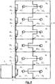
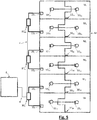
- the figures 3 , 4 and 5 illustrate examples of uses that can be made of the system which is the subject of the invention, with a view to measuring, for example, the temperature in the bearings and crank pinions in a diesel engine M, or Otto type if it is a gas engine. It is understood that other parameters such as pressure, stress, deformation or position in space can be monitored.
- the engine cylinders are arranged "in line” while on the figures 4 and 5 they are in a "Ve" configuration.
- Each antenna 20a, ..., 20f is connected, either alone or in pairs, to an electronic control unit 30 a, ..., f 30.
- motor M is compartmentalized.
- Each compartment M has , ..., M f comprises: an electronic control unit 30 a , ..., 30 f each associated with a single antenna 20 a , ..., 20 f , ( figures 3 and 4 ) or two ( figure 5 ), each of which antennas communicates with sensors SAW 10 1a , 10 2a , 10 3a , ..., 10f , 10f , 10f placed directly inside the compartments, on the parts of which physical parameters and / or analogs must be monitored.
- SAW temperature sensors 10 1a , ..., 10 1f on the pistons there are for example SAW temperature sensors 10 1a , ..., 10 1f on the pistons, SAW temperature sensors 2a , ..., 10 2f on the connecting rods and temperature sensors SAW 3a , ..., 3f on the bearings of the crankshaft.
- SAW sensors of temperature 10 1a , ..., 10 1f on the one hand and 10 2a , ..., 2 2f on the other hand, on the connecting rods of the pairs of cylinders which face each other are arranged, for example. and temperature SAW sensors 3a ,..., 3f on the bearings of the crankshaft.
- Each piece to be monitored is therefore provided with a sensor 10 1a , 10 2a , 10 3a , ..., 10f , 10f , 10f .
- the figures 3 , 4 and 5 illustrate an embodiment where three SAW sensors are arranged per engine compartment. A lower number (for example two SAW sensors) or higher of sensors can however be envisaged.
- the sensors 10 1a, 10 2a, 10 3a, ..., 10 1f, 2f 10 are arranged in the different compartments M, ..., M f so as sensors located in a compartment can not communicate with an antenna connected to a unit electronic control arranged in another compartment, and more specifically in a neighboring compartment.
- these sensors 10 1a , 10 2a , 10 3a , ..., 10f , 10f are arranged in the different compartments M a , ..., M f , according to their resonance frequency.
- each antenna 20a, ..., f 20 is installed within a compartment M, ..., M f.
- an antenna 20 a , ..., 20 f is installed inside each of the compartments M a , ..., M f .
- the units 30 a , ..., 30 f can each be installed outside or inside the compartments M a , ..., M f .
- Each antenna 20a, ..., 20f preferably interrogates only the SAW sensors 10 1a, 10 2a, 10 3a, ..., 10 1f, 2f 10 10 3f located in the engine compartment M, ..., M f .
- Each antenne20 a, ..., f 20 is inactive with respect to the neighboring compartments or different frequency because of those used in its own compartment. There is therefore no risk of interference with the other antennas installed in the other compartments and in particular the immediately adjacent compartments. More particularly, in the example illustrated on the figures 3 and 4 ,
- Each unit 30a, ... 30 f is connected to a single antenna 20 a, ..., f 20 of its own.
- Each unit (for example 30c ) simultaneously communicates, via its antenna (for example 20c ), with all the sensors (for example 10 1c , 10c , 10c ) which are located in its engine compartment (for example). example M c ).
- Each unit 30 ab, 30 cd, ef 30 is connected to two antennas 20 a -20 b, 20 c -20 d, 20 e -20 f, each of these antennas being installed inside a compartment M ..., M f dedicated to him.
- Each unit (for example, 30 ab ) communicates simultaneously, via the pair of antennas to which it is connected (for example 20 to -20 b ), with all the sensors (for example 10 1a , 10 2a , 10a) . 3a and 10b , 10b , 3b ) which are located in the motor compartments in which said antennas are integrated (for example M a and M b ).
- a special bandwidth is allocated to each of them which enables them, for example, to transmit three separate frequency loops within the same compartment M a ,..., M f equipped with three sensors SAW 10 1a , 10 2a , 10 3a , ..., 10 1f , 10 2f , 10 3f .
- the antenna for example 20 a , which is connected to the unit 30 a arranged in the compartment M a , emits frequencies in a predefined frequency band (for example 433 MHz to 439 MHz) which is different from the band of frequencies (for example 439 MHz to 445 MHz) in which emits the antenna 20 b connected to the unit 30 b disposed in another compartment M b .
- the unit 30 has is thus not able to communicate with the sensors 10 1b, 10 2b, 10 3b which are located in the adjacent compartment M b.
- the antennas for example 20 a and 20 b , which are connected in pairs to the unit ab , and which are respectively arranged in the compartment M a and in the compartment M b , each transmit frequencies in a frequency band predefined.
- the unit 30 ab control these antennas so that the frequency band in which the antenna 20 emits a is different from the frequency band in which the antenna 20 emits b.
- the unit 30 ab is thus able to communicate with sensors 10 1a, 10 2a, 10 3a on the one hand, and 10 1b, 10 2b, 10 3b on the other hand which are located respectively in the compartments M a and M b .
- the unit 30 ab but is not able to communicate with the sensors 10 1c, 10 2c, 10 3c which are located in the compartment M c.
- the antennas 20a, ..., 20f communicate with "n” SAW sensor compartment through "2xn” predetermined distinct frequencies.
- the units 30 a , ..., 30 f , 30 ab , ... ef are advantageously connected together by digital communication cables 4. And at least one of these units (e.g. 30 or 30 ef f) is connected to a supervisory equipment 6 so that all of said units to communicate therewith.
- the supervision equipment 6 is for example a computer on which all the information received by the different units 30 a , ..., 30 f , 30 ab , ... ef , are visualized and / or processed and / or analyzed.
- the system that is the subject of the invention comprises a single antenna per compartment and, on the other hand, the electronic control units are connected to each other and to the supervision equipment by a digital communication cable or a digital bus, said system reduces cabling constraints by optimizing the space dedicated to it, both inside and outside the engine.
- the sensors SAW 10 1a , 10 2a , 10 3a , ..., 10f , 10f , 10f , arranged in the same compartment can emit frequencies in a frequency band different from those emitted by the acoustic wave sensors of surface located in another nearby compartment. This avoids any harmful interference between the signals emitted by SAW sensors immediately adjacent compartments, and therefore physically close.
- a specific bandwidth can be allocated to each of the SAW sensors 10 1a, 10 2a, 10 3a, ..., 10 1f, 2f 10 10 3f, which allows them, for example, broadcasting in return to each of the antennas 20 a ,..., 20 f three distinct narrow strips inside the same compartment M a , ...., M f , equipped with three SAW sensors.
- the bandwidth allocated to each of the SAW sensors is preferably narrow, for example defined on an interval (or increment) of 2 MHz.
- the sensors 10 1a, 10 2a, 10 3a communicating with the antenna 20 is connected to the unit 30 a, and which are disposed in the compartment M, in turn issue frequencies in predefined frequency bands respectively for example 433 MHz at 435 MHz, 435 MHz at 437 MHz, and 437 MHz at 439 MHz. These frequency bands are different from the frequency bands (for example 439 MHz to 441 MHz, 441 MHz to 443 MHz, and 443 MHz to 445 MHz) in which the sensors 1b , 10 2b , 3b transmit back to the receiver .
- antenna 20b connected to the unit 30b , and arranged in the neighboring compartment M b .
- the unit 30 has is thus not disturbed by the sensors 10 1b, 10 2b, 10 3b which are located in the compartment M b.
- an antenna 20a, ..., 20f that is installed in a compartment M, ..., M f, emit frequencies within a predetermined frequency band which is different from the frequency band in which the antenna emits in another compartment.
- all antennas 20a, ..., 20f may each transmit simultaneously several discrete frequencies covering all the frequencies of all the resonance sensors 10 1a, 10 2a, 10 3a, ..., 10 1f, 2f , including, but not limited to, frequencies close to the resonant frequencies of the sensors that are located in the compartment dedicated to them.
- All antennas 20 a, ..., f 20 are thus identical and dimensioned to be able to emit the same frequency spectrum broadband.
Description
L'invention a pour objet un système dédié à la surveillance des paramètres physiques et/ou analogiques des pièces d'un moteur.The subject of the invention is a system dedicated to monitoring the physical and / or analog parameters of the parts of an engine.
L'invention concerne les techniques de mesures et de contrôle de paramètres variés sur des pièces mécaniques mobiles et/ou inaccessibles d'un moteur, destinés en particulier à la surveillance et à la sécurité des moteurs alternatifs à combustion interne.The invention relates to techniques for measuring and controlling various parameters on moving and / or inaccessible mechanical parts of an engine, intended in particular for the monitoring and safety of reciprocating internal combustion engines.
Il est primordial d'assurer le contrôle des paramètres significatifs de l'intégrité et du bon fonctionnement des organes et composants du moteur. Pour cela, la méthode habituelle consiste à effectuer des mesures directement sur ces composants. En cas de variation anormale d'un facteur comme la température, la pression ou encore la contrainte, il est alors possible de stopper le système avant qu'un incident ne survienne et que le moteur cesse de fonctionner. C'est par exemple le cas lorsqu'une pièce est insuffisamment lubrifiée ou soumise à une température trop élevée. Selon l'utilisation qui est faite du matériel, les conséquences sanitaires ou économiques peuvent être très importantes. Permettre un arrêt anticipé et automatique du système si un paramètre anormal est constaté est un avantage majeur. L'efficacité d'un tel dispositif est donc en grande partie tributaire de sa rapidité.It is essential to ensure the control of the significant parameters of the integrity and the good functioning of the organs and components of the engine. For this, the usual method is to make measurements directly on these components. In case of abnormal variation of a factor such as temperature, pressure or stress, it is then possible to stop the system before an incident occurs and the engine stops working. This is for example the case when a part is insufficiently lubricated or subjected to a temperature too high. Depending on how the material is used, the health or economic consequences can be very important. Allowing an early and automatic shutdown of the system if an abnormal parameter is found is a major advantage. The effectiveness of such a device is therefore largely dependent on its speed.
L'état de la technique décrit plusieurs systèmes permettant d'effectuer un tel contrôle.The state of the art describes several systems for carrying out such a control.
On connait par exemple par le document brevet
Dans ce dispositif, plusieurs aspects contraignant sont à relever. Tout d'abord, c'est la thermistance qui définit la réponse du capteur suivant des variations non-linéaires, ce qui est gênant puisque selon la qualité et la précision de cet élément, les mesures peuvent être faussées sur de grandes plages de variation. De plus, le transmetteur récepteur génère un champ magnétique par lequel les ondes circulent. Or ce champ magnétique n'est pas entièrement détecté par le capteur, ce qui entraîne la perte d'une partie des ondes émises et reçues par le transmetteur/récepteur. La précision de la mesure dépend donc de la qualité de la bobine du système et des calibrations fastidieuses à réaliser pour chaque capteur en usine. Ensuite, la distance maximale de lecture séparant le transmetteur/récepteur du capteur n'est que de l'ordre de 2 mm, ce qui est assez faible et peut poser problème pour certaines pièces en mouvement, par exemple par rapport aux jeux de fonctionnement qui peuvent être du même ordre de grandeur. Ces problèmes ne permettent pas de répondre de manière satisfaisante aux attentes des utilisateurs.In this device, several constraining aspects are to be noted. First, it is the thermistor that defines the response of the sensor according to non-linear variations, which is inconvenient since according to the quality and accuracy of this element, the measurements can be falsified over large ranges of variation. In addition, the receiver transmitter generates a magnetic field through which the waves circulate. However, this magnetic field is not fully detected by the sensor, which results in the loss of part of the waves emitted and received by the transmitter / receiver. The accuracy of the measurement therefore depends on the quality of the system coil and the tedious calibrations to be performed for each sensor at the factory. Then, the maximum reading distance separating the transmitter / receiver from the sensor is only of the order of 2 mm, which is quite low and can pose a problem for some moving parts, for example compared to the operating sets which can be of the same order of magnitude. These problems do not provide a satisfactory answer to user expectations.
On connait également par le document brevet
Ce système présente plusieurs inconvénients. D'abord, c'est un système qui interroge chaque capteur SAW 1 via une seule et même unité électronique de contrôle 3. Pour cela, il utilise le multiplexage d'antennes 2, méthode permettant d'interroger chaque capteur 1 de manière séquentielle. Or, cette méthode est contraignante puisqu'elle augmente considérablement le temps d'attente entre chaque opération d'interrogation des capteurs 1. En effet, dans ce système, l'unité de contrôle unique 3 interroge successivement les capteurs 1 en envoyant tout d'abord un signal via des câbles coaxiaux 4 reliés aux antennes 2. Celles-ci communiquent avec les capteurs SAW 1. Le signal réponse suit le cheminement inverse. La réception et le traitement des multiples signaux reçus par l'unité de contrôle électronique 3 augmentent la durée de l'analyse. De plus, l'environnement métallique du moteur a pour effet de conduire à la perte d'une partie de ces signaux et donc de réduire l'efficacité des mesures effectuées. En outre, le processus d'interrogation des capteurs SAW 1 requiert que chacun dispose d'une antenne 2 qui lui est dédiée dans le compartiment moteur. Chaque communication entre l'antenne 2 et son capteur SAW 1 s'effectue par l'intermédiaire d'une seule et même fréquence pour toutes les antennes 2. L'usage de cette fréquence unique impose donc des interrogations séquentielles de chaque capteur 1 pour éviter les interférences entre les réponses de capteurs proches.This system has several disadvantages. First, it is a system that interrogates each SAW sensor 1 via a single electronic control unit 3. For this, it uses the antenna multiplexing 2 method to interrogate each sensor 1 sequentially. However, this method is restrictive since it considerably increases the waiting time between each interrogation operation of the sensors 1. In fact, in this system, the single control unit 3 successively interrogates the sensors 1 by sending everything from first a signal via
L'un des avantages de ce système par rapports aux autres systèmes connus de l'art antérieur, est la plus grande distance de lecture des capteurs SAW 1 par les antennes 2, laquelle distance est portée jusqu'à 5 cm. Mais cette distance reste encore insuffisante pour affranchir l'utilisateur des contraintes d'installation à l'intérieur du moteur. Par ailleurs, le système nécessite que l'unité de contrôle 3 soit reliée aux antennes 2 par autant de câbles coaxiaux 4 et impose donc des contraintes d'espace et de câblage très gênantes à l'extérieur du moteur.One of the advantages of this system over other known systems of the prior art, is the greater reading distance of the SAW sensors 1 by the antennas 2, which distance is increased up to 5 cm. But this distance is still insufficient to free the user from installation constraints inside the engine. Furthermore, the system requires that the control unit 3 is connected to the antennas 2 by as many
Les documents brevets
Face à cet état des choses, l'objectif principal de l'invention est de remédier aux inconvénients précités, et notamment d'améliorer les capacités de mesure des pièces mobiles difficiles d'accès.Faced with this state of affairs, the main objective of the invention is to overcome the aforementioned drawbacks, and in particular to improve the measurement capabilities of moving parts that are difficult to access.
Un autre objectif de l'invention est d'obtenir une analyse plus rapide et plus précise que celles obtenues avec les systèmes de l'art antérieur, évitant les contraintes imposées par la méthode de multiplexage enseignée dans le document brevet
L'invention a également pour objectif de proposer un système de surveillance permettant de réduire les contraintes d'espace et de câblage par rapport à celles imposées dans le système du document brevet
L'invention a encore pour objectif d'améliorer les performances vis-à-vis des problématiques liées à l'environnement métallique du carter du moteur.The invention also aims to improve performance vis-à-vis the problems related to the metal environment of the engine housing.
La solution proposée par l'invention est un système de surveillance de paramètres physiques et/ou analogiques relatifs à des pièces d'un moteur, ledit système comprenant au moins une unité électronique de contrôle configurée pour interroger, par l'intermédiaire d'au moins une antenne, un capteur à ondes acoustiques de surface (ou capteur SAW) situé sur une desdites pièces.The solution proposed by the invention is a system for monitoring physical and / or analog parameters relating to parts of an engine, said system comprising at least one electronic control unit configured to interrogate, via at least one an antenna, a surface acoustic wave sensor (or SAW sensor) located on one of said parts.
Ce système est remarquable en ce que :
- le moteur est compartimenté, chaque compartiment comportant plusieurs pièces mobiles dont des paramètres physiques et/ou analogiques doivent être surveillés,
- chacune de ces pièces à surveiller est pourvue d'un capteur à ondes acoustiques de surface, ces capteurs ayant chacun une fréquence de résonance distincte qui leur est propre,
- une antenne est installée à l'intérieur de chacun des compartiments, chacune de ces antennes étant reliée, seule ou par paire, à une unité électronique de contrôle,
- chaque antenne est commandée par l'unité électronique de contrôle à laquelle elle est reliée, pour émettre simultanément plusieurs fréquences distinctes proches des fréquences de résonance des capteurs qui sont situés dans le compartiment moteur de ladite antenne, de manière à communiquer simultanément avec tous ces capteurs.
- the engine is compartmentalized, each compartment comprising several moving parts whose physical and / or analog parameters must be monitored,
- each of these parts to be monitored is provided with a surface acoustic wave sensor, these sensors each having a distinct resonant frequency of their own,
- an antenna is installed inside each of the compartments, each of these antennas being connected, alone or in pairs, to an electronic control unit,
- each antenna is controlled by the electronic control unit to which it is connected, to simultaneously transmit several distinct frequencies close to the resonance frequencies of the sensors which are located in the engine compartment of said antenna, so as to communicate simultaneously with all these sensors .
Dans chaque compartiment, une seule antenne est maintenant capable d'interroger simultanément tous les capteurs qui y sont installés. Les capacités de mesures sont donc non seulement décuplées, mais l'analyse des paramètres devient plus rapide et plus précise que celles obtenues avec les systèmes de l'art antérieur en particulier celle décrite dans le document brevet
D'autres caractéristiques de l'invention sont listées ci-dessous, chacune de ces caractéristiques pouvant être considérée seule ou en combinaison avec les caractéristiques remarquables définies ci-dessus :
- L'antenne qui est installée dans un compartiment peut émettre des fréquences dans une bande de fréquences prédéfinie qui est différente de la bande de fréquences dans laquelle émet l'antenne disposée dans un autre compartiment.
- Les capteurs à ondes acoustiques de surface disposés dans un même compartiment peuvent émettre en retour des fréquences dans une bande de fréquences différentes de celles émise en retour par les capteurs à ondes acoustiques de surface disposés dans un autre compartiment voisin.
- Les capteurs à ondes acoustiques de surface disposés dans un même compartiment peuvent chacun émettre des fréquences dans une bande de fréquences étroite, définie sur un intervalle de 2 MHz.
- Chaque unité électronique de contrôle peut être reliée à une seule antenne qui lui est propre ou reliée à deux antennes, chacune de ces antennes étant installée à l'intérieur d'un compartiment qui lui est dédié.
- Chaque capteur à ondes acoustiques de surface comprend avantageusement une antenne qui lui est propre.
- Chaque capteur à ondes acoustiques de surface est préférentiellement installé sur une pièce qui est mobile mais peut être installé sur une pièce qui est fixe.
- Les capteurs sont préférentiellement agencés dans les différents compartiments de manière à ce que des capteurs situés dans un compartiment ne puissent pas communiquer avec une antenne installée dans un autre compartiment.
- Les unités électroniques de contrôle peuvent être chacune installées à l'extérieur ou à l'intérieur du compartiment.
- Les unités électroniques de contrôle peuvent être reliées entre-elles par des câbles de communication numérique, au moins une desdites unités étant reliée à un matériel de supervision de sorte que toutes lesdites unités puissent communiquer avec ledit matériel.
- Les unités électroniques de contrôle peuvent communiquer avec un matériel de supervision par l'intermédiaire de bus numérique.
- Chaque antenne peut utiliser des fréquences ISM pour communiquer avec les capteurs qui leur sont associés.
- Chaque antenne peut utiliser des fréquences ISM comprises entre 433 MHz et 445 MHz ou des fréquences ISM comprises entre 866 MHz et 890 MHz.
- Chaque antenne peut utiliser des fréquences comprises entre 423 MHz et 435 MHz, ou des fréquences comprises entre 846 MHz et 870 MHz, pour communiquer avec les capteurs qui leur sont associés.
- Chaque antenne utilisée est avantageusement une antenne « quart d'onde » ou PIFA.
- The antenna that is installed in a compartment may transmit frequencies in a predefined frequency band that is different from the frequency band in which the antenna is located in another compartment.
- Surface acoustic wave sensors arranged in the same compartment may return frequencies in a frequency band different from those transmitted in return by the surface acoustic wave sensors arranged in another neighboring compartment.
- Surface acoustic wave sensors arranged in the same compartment can each transmit frequencies in a narrow frequency band, defined over a range of 2 MHz.
- Each electronic control unit can be connected to a single antenna which is specific to it or connected to two antennas, each of these antennas being installed inside a compartment which is dedicated to it.
- Each surface acoustic wave sensor advantageously comprises an antenna of its own.
- Each surface acoustic wave sensor is preferably installed on a part that is movable but can be installed on a part that is fixed.
- The sensors are preferably arranged in the different compartments so that sensors located in one compartment can not communicate with an antenna installed in another compartment.
- The electronic control units can each be installed outside or inside the compartment.
- The electronic control units can be connected to each other by digital communication cables, at least one of said units being connected to a supervision equipment so that all said units can communicate with said equipment.
- Electronic control units can communicate with supervision equipment via digital bus.
- Each antenna can use ISM frequencies to communicate with the sensors associated with them.
- Each antenna may use ISM frequencies between 433 MHz and 445 MHz or ISM frequencies between 866 MHz and 890 MHz.
- Each antenna can use frequencies between 423 MHz and 435 MHz, or frequencies between 846 MHz and 870 MHz, to communicate with the sensors associated with them.
- Each antenna used is advantageously a "quarter wave" antenna or PIFA.
Un autre aspect de l'invention concerne un procédé de surveillance de paramètres physiques et/ou analogiques relatifs à des pièces d'un moteur, en interrogeant, par l'intermédiaire d'au moins une antenne un capteur à ondes acoustiques de surface situé sur une desdites pièces. Ce procédé est remarquable en ce qu'il comprend les étapes suivantes :
- compartimenter le moteur de sorte que chaque compartiment comporte plusieurs pièces dont des paramètres physiques et/ou analogiques doivent être surveillés,
- disposer sur chacune de ces pièces à surveiller, un capteur à ondes acoustiques de surface, ces capteurs ayant chacun une fréquence de résonance distincte qui leur est propre,
- installer une antenne à l'intérieur de chaque compartiment,
- relier chacune de ces antennes, seule ou par paire, à une unité électronique de contrôle,
- interroger chaque capteur en émettant simultanément, depuis chaque antenne, plusieurs fréquences distinctes proches des fréquences de résonance des capteurs qui sont situés dans le compartiment moteur de ladite antenne, de manière à communiquer simultanément avec tous ces capteurs.
- compartmentalize the engine so that each compartment has several parts whose physical and / or analog parameters must be monitored,
- have on each of these parts to be monitored, a surface acoustic wave sensor, these sensors each having a distinct resonant frequency of their own,
- install an antenna inside each compartment,
- connect each of these antennas, alone or in pairs, to an electronic control unit,
- interrogating each sensor by simultaneously transmitting, from each antenna, several distinct frequencies close to the resonance frequencies of the sensors which are located in the engine compartment of said antenna, so as to simultaneously communicate with all these sensors.
D'autres avantages et caractéristiques de l'invention apparaîtront mieux à la lecture de la description d'un mode de réalisation préféré qui va suivre, en référence aux dessins annexés, réalisés à titre d'exemples indicatifs et non limitatifs et sur lesquels :
- la
figure 1 précitée illustre un système de surveillance connu de l'art antérieur, et notamment décrit dans le document brevetWO 00/62029 - la
figure 2 illustre un système de surveillance conforme à l'invention agencé dans un des compartiments du moteur, - la
figure 3 schématise l'agencement d'un système conforme à l'invention dans différents compartiments d'un moteur thermique dont les cylindres sont disposés « en ligne », - la
figure 4 schématise l'agencement d'un système conforme à l'invention dans différents compartiments d'un moteur thermique dont les cylindres sont disposés en « Vé », - la
figure 5 schématise un autre agencement d'un système conforme à l'invention dans différents compartiments d'un moteur thermique dont les cylindres sont disposés en « Vé ».
- the
figure 1 above illustrates a monitoring system known from the prior art, and in particular described in the patent documentWO 00/62029 - the
figure 2 illustrates a monitoring system according to the invention arranged in one of the compartments of the engine, - the
figure 3 schematizes the arrangement of a system according to the invention in different compartments of a heat engine whose cylinders are arranged "in line", - the
figure 4 schematizes the arrangement of a system according to the invention in different compartments of a heat engine whose cylinders are arranged in "V", - the
figure 5 schematically another arrangement of a system according to the invention in different compartments of a heat engine whose cylinders are arranged in "V".
En se rapportant à la
Sur la
Alors que dans les systèmes de l'art antérieur, chaque antenne est généralement associée à un unique capteur SAW, l'invention propose maintenant de faire communiquer l'antenne 20a avec plusieurs capteurs SAW 101, 102, 103. La
Les capteurs SAW 101, 102, 103 ont chacun une fréquence de résonance distincte qui leur est propre. L'unité 30a intègre un émetteur qui envoie simultanément plusieurs signaux électromagnétiques d'interrogation vers l'antenne 20a, chacun desdits signaux ayant une fréquence proche de la fréquence de résonance des capteurs SAW 101, 102, 103. L'antenne 20a est ainsi configurée pour émettre plusieurs boucles de fréquences distinctes (une par capteur SAW). Les signaux reçus puis émis par l'antenne 20a sont transmis aux antennes « mobiles » des capteurs SAW 101, 102, 103, puis convertis en ondes acoustiques de surface qui se propagent à la surface des substrats utilisés par lesdits capteurs SAW. Les propriétés de ces ondes de surface, et notamment leur longueur d'onde, sont modifiées en fonction des paramètres physiques et/ou analogiques (température, pression, contrainte, déformation, position dans l'espace...) des pièces sur lesquelles sont agencés les capteurs SAW 101, 102, 103. Ces paramètres affectent plus particulièrement la fréquence de résonance de chaque capteur SAW 101, 102, 103. Ces derniers réémettent vers l'antenne 20a un signal de réponse à une fréquence de résonance propre qui porte l'information liée aux paramètres à surveiller. En d'autres termes, la réponse des capteurs SAW 101, 102, 103 est une variation en fréquence fonction des paramètres à surveiller, ce qui est plus avantageux qu'un principe basé sur les lignes de retard. Les signaux de réponse reçus par l'antenne 20a sont ensuite transférés vers l'unité 30a qui intègre un récepteur approprié configuré pour extraire les informations recherchées en fonction des fréquences effectivement reçues. L'unité 30a peut ainsi interroger les différents capteurs SAW 101, 102, 103 par l'intermédiaire de la seule antenne 20a.The
Selon une caractéristique avantageuse de l'invention, l'antenne 20a utilise des fréquences ISM pour communiquer avec les capteurs 101, 102, 103. Les bandes ISM (pour l'acronyme Industriel, Scientifique et Médical) sont des bandes de fréquences dont l'utilisation pour des applications industrielles, scientifiques, médicales, domestiques ou similaire, est admise sans aucune demande d'autorisation auprès des autorités[]. Pour l'Union européenne, les bandes de fréquences ISM sont définies dans la norme EN 55011 et pour les USA, par la publication FCC Part 18. L'utilisation des bandes de fréquences ISM autorise une distance de lecture pouvant aller jusqu'à 100 cm, suivant le positionnement des capteurs SAW 101, 102, 103 dans le moteur et la géométrie de celui-ci. L'utilisation de fréquences ISM basses, ou proche de ces fréquences, c'est-à-dire comprises entre 433 MHz et 445 MHz, permet de meilleures performances vis-à-vis des problématiques de réflexions, diffractions et d'absorptions des ondes électromagnétiques dans l'environnement métallique du carter du moteur. D'autres types de fréquences convenant à l'Homme du métier pourraient toutefois être utilisés, notamment des fréquences ISM, ou proche de ces fréquences, comprises entre 866 MHz et 890 MHz. Ces fréquences ISM plus élevées permettent de réduire la taille des antennes, de sorte que le système de surveillance objet de l'invention puisse être installé dans des moteurs plus petits.According to an advantageous characteristic of the invention, the
L'antenne 20a peut également utiliser d'autres fréquences très proches des fréquences ISM. En effet, certains capteurs SAW peuvent avoir des fréquences légèrement situées au-delà des bandes ISM (de 0,5 MHz à 10 MHz par exemple), du fait d'un éventuel effet « cage de Faraday » des compartiments Ma, Mb, Mc. Pour communiquer avec les capteurs 101, 102, 103 qui lui sont associés, l'antenne 20a peut par exemple utiliser des fréquences comprises entre 423 MHz et 435 MHz et qui sont proches des fréquences ISM basses, ou des fréquences comprises 846 MHz et 870 MHz et qui sont proches des fréquences ISM hautes.The
Les
Chaque antenne 20a, ..., 20f, est reliée, seule ou par paire, à une unité électronique de contrôle 30a, ..., 30f. Sur l'exemple illustré des
Les capteurs 101a, 102a, 103a, ..., 101f, 102f, sont agencés dans les différents compartiments Ma, ..., Mf de manière à ce que des capteurs situés dans un compartiment ne puissent pas communiquer avec une antenne reliée à une unité électronique de contrôle disposée dans un autre compartiment, et plus spécifiquement dans un compartiment voisin. En pratique, ces capteurs 101a, 102a, 103a, ..., 101f, 102f, sont agencés dans les différents compartiments Ma, ..., Mf, suivant leur fréquence de résonance. Pour optimiser la qualité des mesures, chaque antenne 20a, ..., 20f est installée à l'intérieur d'un compartiment Ma, ..., Mf. En d'autres termes, une antenne 20a, ..., 20f est installée à l'intérieur de chacun des compartiments Ma, ..., Mf. Les unités 30a, ..., 30f peuvent être chacune installées à l'extérieur ou à l'intérieur des compartiments Ma, ..., Mf.The
Chaque antenne 20a, ..., 20f interroge préférentiellement uniquement les capteurs SAW 101a, 102a, 103a, ..., 101f, 102f, 103f situés dans son compartiment moteur Ma, ..., Mf. Chaque antenne20a, ..., 20f reste inactive vis à vis du ou des compartiments voisins du fait de fréquences différentes de celles utilisées dans son propre compartiment. Il n'y a donc pas de risque d'interférence avec les autres antennes installées dans les autres compartiments et notamment les compartiments immédiatement voisins. Plus particulièrement, dans l'exemple illustré sur les
Dans l'exemple illustré sur la
Pour éviter toute interférence nuisible entre les signaux émis par les différentes antennes 20a, ..., 20f dans le moteur M, une bande passante spéciale est allouée à chacune d'elles ce qui leur permet, par exemple, d'émettre trois boucles de fréquences distinctes à l'intérieur d'un même compartiment Ma, ..., Mf équipé de trois capteurs SAW 101a, 102a, 103a, ..., 101f, 102f, 103f. Plus particulièrement, en se rapportant à l'exemple illustré sur les
Dans l'exemple de réalisation de la
Préférentiellement, les antennes 20a, ..., 20f communiquent avec « n » capteur SAW par compartiment, grâce à « 2xn » fréquences distinctes préétablies.Preferably, the antennas 20a, ..., 20f communicate with "n" SAW sensor compartment through "2xn" predetermined distinct frequencies.
Les unités 30a, ..., 30f, 30ab,... 30ef, sont avantageusement reliées entre-elles par des câbles de communication numérique 4. Et au moins une de ces unités (par exemple 30f ou 30ef) est reliée à un matériel de supervision 6 de sorte que toutes lesdites unités puissent communiquer avec ce matériel. Le matériel de supervision 6 est par exemple un ordinateur sur lequel toutes les informations reçues par les différentes unités 30a, ..., 30f, 30ab,... 30ef, sont visualisées et/ou traitées et/ou analysées. Les unités 30a, ..., 30f, 30ab,... 30ef, peuvent également communiquer avec le matériel de supervision par l'intermédiaire de bus numériques qui fonctionnement grâce à des protocoles de communication tels que CANopen, SAE J1939, Modbus, etc. Puisque d'une part le système objet de l'invention comprend une seule antenne par compartiment et que d'autre part, les unités électroniques de contrôle sont reliées entre elles et au matériel de supervision par un câble de communication numérique ou un bus numérique, ledit système réduit les contraintes liées au câblage en optimisant l'espace qui lui est consacré, à la fois à l'intérieur et à l'extérieur du moteur.The
Les capteurs SAW 101a, 102a, 103a, ..., 101f, 102f, 103f, disposés dans un même compartiment peuvent émettre des fréquences dans une bande de fréquences différentes de celles émise par les capteurs à ondes acoustiques de surface disposés dans un autre compartiment voisin. On évite ainsi toute interférence nuisible entre les signaux émis en retour par des capteurs SAW de compartiments immédiatement voisins, et donc physiquement proches. Pour ce faire, une bande passante spécifique peut être allouée à chacun des capteurs SAW 101a, 102a, 103a, ..., 101f, 102f, 103f, ce qui leur permet, par exemple, d'émettre en retour vers chacune des antennes 20a,...,20f trois bandes étroites distinctes à l'intérieur d'un même compartiment Ma,....,Mf, équipé de trois capteurs SAW. Pour optimiser l'énergie nécessaire au fonctionnement de l'installation, la bande passante allouée à chacun des capteurs SAW est préférentiellement étroite, par exemple définie sur un intervalle (ou incrément) de 2 MHz. Plus particulièrement, en se rapportant à l'exemple illustré sur les
Les exemples de réalisation de l'invention présentés ci-dessus ont été choisis eu égard à leur caractère concret. Il ne serait cependant pas possible de répertorier de manière exhaustive tous les modes de réalisation que recouvre cette invention. En particulier, toute étape ou moyen décrit peut être remplacé par une étape ou un moyen équivalent, sans sortir du cadre de la présente invention.The embodiments of the invention presented above have been chosen in view of their concrete nature. It would not be possible, however, to exhaustively list all the embodiments covered by this invention. In particular, any step or means described may be replaced by a step or equivalent means, without departing from the scope of the present invention.
Claims (19)
- System for monitoring physical and/or analogue parameters relating to parts of an engine, said system comprising at least one electronic control unit (30a) configured to interrogate, via at least one antenna (20a), a surface acoustic wave sensor situated on one of said parts,
being characterized in that:- the engine (M) is divided up into compartments, each compartment (Ma, ..., Mf) comprising a number of moving or fixed parts of which the physical and/or analogue parameters have to be monitored,- each of these parts to be monitored is provided with a surface acoustic wave sensor (101a, 102a, 103a, ..., 101f, 102f, 103f), these sensors each having a distinct resonance frequency which is specific to them,- an antenna (20a, ..., 20f) is installed inside each of the compartments (Ma, ..., Mf), each of these antennas being linked, alone or in pairs, to an electronic control unit (30a, ..., 30f, 30ab, ..., 30ef),- each antenna (20a, ..., 20f) is controlled by the electronic control unit (30a, ..., 30f, 30ab, ..., 30ef) to which it is linked to simultaneously emit a number of distinct frequencies close to the resonance frequencies of the sensors (101a, 102a, 103a, ..., 101f, 102f, 103f) which are situated in the engine compartment (Ma, ..., Mf) of said antenna, so as to simultaneously communication with all these sensors (101a, 102a, 103a, ..., 101f, 102f, 103f). - System according to Claim 1, in which the antenna (20a, ..., 20f) which is installed in one compartment (Ma, ..., Mf) emits frequencies in a predefined frequency band which is different from the frequency band in which the antenna arranged in another compartment emits.
- System according to one of the preceding claims, in which the surface acoustic wave sensors (101a, 102a, 103a, ..., 101f, 102f, 103f) arranged in a same compartment (Ma, ..., Mf), emit in return frequencies in a band of frequencies different from those emitted in return by the surface acoustic wave sensors arranged in another neighbouring compartment.
- System according to one of the preceding claims, in which the surface acoustic wave sensors (101a, 102a, 103a, ..., 101f, 102f, 103f) arranged in a same compartment (Ma, ..., Mf) each emit frequencies in a narrow frequency band, defined over an interval of 2MHz.
- System according to one of Claims 1 to 4, in which each electronic control unit (30a, ..., 30f) is linked to a single antenna (20a, ..., 20f) which is specific to it.
- System according to one of Claims 1 to 4, in which each electronic control unit (30ab, ..., 30ef) is linked to two antennas (20a, ..., 20t), each of these antennas being installed inside a compartment (Ma, ..., Mf) which is dedicated to it.
- System according to one of the preceding claims, in which each surface acoustic wave sensor (101a, 102a, 103a, ..., 101f, 102f, 103f) comprises an antenna which is specific to it.
- System according to one of the preceding claims, in which each surface acoustic wave sensor (101a, 102a, 103a, ..., 101f, 102f, 103f) is installed on a moving part.
- System according to Claim 1, in which the sensors ( 101a, 102a, 103a, ..., 101f, 102f) are arranged in the different compartments (Ma, ..., Mf) in such a way that the sensors situated in one compartment cannot communicate with an antenna (20a, ..., 20t) installed in another compartment.
- System according to one of Claims 1 to 9, in which the electronic control units (30a, ..., 30f, 30ab, ..., 30ef) are each installed outside or inside the compartment (Ma, ..., Mf).
- System according to one of Claims 1 to 9, in which the electronic control units (30a, ..., 30f, 30ab, ..., 30ef) are linked together by digital communication cables (4), at least one of said units being linked to supervisory hardware (6) so that all of said units can communicate with said hardware.
- System according to one of Claims 1 to 9, in which the electronic control units (30a, ..., 30f, 30ab, ..., 30ef) communicate with supervisory hardware (6) via a digital bus.
- System according to one of the preceding claims, in which each antenna (20a, ..., 20f) uses ISM frequencies to communicate with the sensors (101a, 102a, 103a, ..., 101f, 102f) which are associated therewith.
- System according to Claim 13, in which each antenna (20a, ..., 20f) uses ISM frequencies lying between 433 MHz and 445 MHz.
- System according to Claim 13, in which each antenna (20a, ..., 20f) uses ISM frequencies lying between 866 MHz and 890 MHz.
- System according to one of Claims 1 to 12, in which each antenna (20a, ..., 20f) uses frequencies lying between 423 MHz and 435 MHz, to communicate with the sensors (101a, 102a, 103a, ..., 101f, 102f) which are associated therewith.
- System according to one of Claims 1 to 12, in which each antenna (20a, ..., 20f) uses frequencies lying between 846 MHz and 870 MHz, to communicate with the sensors (101a, 102a, 103a, ..., 101f, 102f) which are associated therewith.
- System according to one of the preceding claims, in which each antenna (20a, ..., 20f) used is a "quarter wave" or PIFA antenna.
- Method for monitoring physical and/or analogue parameters relating to parts of an engine, by interrogating, via at least one antenna (20a), a surface acoustic wave sensor situated on one of said parts, being characterized in that it comprises the following steps:- dividing up the engine (M) into compartments such that each compartment (Ma, ..., Mf) comprises a number of parts whose physical and/or analogue parameters must be monitored,- arranging on each of these parts to be monitored, a surface acoustic wave sensor (101a, 102a, 103a, ..., 101f, 102f, 103f), these sensors each having a distinct resonance frequency which is specific to them,- installing an antenna (20a, ..., 20f) inside each compartment (Ma, ..., Mf),- linking each of these antennas (20a, ..., 20f), alone or in pairs, to an electronic control unit (30a, ..., 30f, 30ab, ..., 30ef),- interrogating each sensor (101a, 102a, 103a, ..., 101f, 102f, 103f) by simultaneously emitting, from each antenna (20a, ..., 20f), a number of distinct frequencies close to the resonance frequencies of the sensors (101a, 102a, 103a, ..., 101f, 102f, 103f) which are situated in the engine compartment (Ma, ..., Mf) of said antenna, so as to simultaneously communicate with all these sensors (101a, 102a, 103a, ..., 101f, 102f, 103f).
Priority Applications (1)
| Application Number | Priority Date | Filing Date | Title |
|---|---|---|---|
| PL13805426T PL2907321T3 (en) | 2012-10-10 | 2013-10-09 | System dedicated to monitoring the physical and/or analogue parameters of the parts of an engine |
Applications Claiming Priority (2)
| Application Number | Priority Date | Filing Date | Title |
|---|---|---|---|
| FR1202706A FR2996599B1 (en) | 2012-10-10 | 2012-10-10 | SYSTEM FOR MONITORING THE PHYSICAL AND / OR ANALOGIC PARAMETERS OF THE PARTS OF AN ENGINE |
| PCT/FR2013/052409 WO2014057219A1 (en) | 2012-10-10 | 2013-10-09 | System dedicated to monitoring the physical and/or analogue parameters of the parts of an engine |
Publications (2)
| Publication Number | Publication Date |
|---|---|
| EP2907321A1 EP2907321A1 (en) | 2015-08-19 |
| EP2907321B1 true EP2907321B1 (en) | 2016-12-07 |
Family
ID=47424954
Family Applications (1)
| Application Number | Title | Priority Date | Filing Date |
|---|---|---|---|
| EP13805426.7A Active EP2907321B1 (en) | 2012-10-10 | 2013-10-09 | System dedicated to monitoring the physical and/or analogue parameters of the parts of an engine |
Country Status (7)
| Country | Link |
|---|---|
| US (1) | US9766161B2 (en) |
| EP (1) | EP2907321B1 (en) |
| CN (1) | CN104685901B (en) |
| DK (1) | DK2907321T3 (en) |
| FR (1) | FR2996599B1 (en) |
| PL (1) | PL2907321T3 (en) |
| WO (1) | WO2014057219A1 (en) |
Families Citing this family (5)
| Publication number | Priority date | Publication date | Assignee | Title |
|---|---|---|---|---|
| CN108476565B (en) * | 2015-12-18 | 2021-08-13 | 昕诺飞控股有限公司 | Lighting strip |
| CN105806625A (en) * | 2016-03-21 | 2016-07-27 | 中北大学 | Joint testing method and device for different core components in engine |
| US10838053B2 (en) | 2018-07-03 | 2020-11-17 | General Electric Company | System and method of measuring blade clearance in a turbine engine |
| CN111121988B (en) * | 2019-12-30 | 2021-05-25 | 中国船舶重工集团公司第七一一研究所 | Temperature measuring device and temperature measuring method suitable for V-shaped engine connecting rod bearing bush |
| CN113027608B (en) * | 2021-04-06 | 2022-03-01 | 华中科技大学 | Internal combustion engine piston top surface transient temperature remote measuring system and installation method thereof |
Family Cites Families (8)
| Publication number | Priority date | Publication date | Assignee | Title |
|---|---|---|---|---|
| EP0051035A1 (en) | 1980-08-22 | 1982-05-05 | Controle Mesure Regulation - Cmr (S.A.) | Device for controlling the temperature (or another binary physical parameter) of periodically moving objects |
| JP2000504553A (en) | 1996-01-31 | 2000-04-11 | シーメンス アクチエンゲゼルシヤフト | Closed equipment |
| NO322272B1 (en) * | 1999-03-26 | 2006-09-04 | Kongsberg Maritime As | Sensor and temperature monitoring system inside hard-to-reach, moving parts |
| US7911324B2 (en) * | 2001-02-16 | 2011-03-22 | Automotive Technologies International, Inc. | Method and system for obtaining information about RFID-equipped objects |
| DE10325667A1 (en) * | 2003-06-06 | 2005-03-03 | Fag Kugelfischer Ag & Co. Ohg | Roller bearing rotating component sensor system uses SAW and BAW sensor with responses transmitted through shared antenna as frequency separated narrow band signals |
| US7089099B2 (en) * | 2004-07-30 | 2006-08-08 | Automotive Technologies International, Inc. | Sensor assemblies |
| EP2555930B1 (en) * | 2010-04-09 | 2014-01-22 | Pirelli Tyre S.P.A. | A tyre sensor device |
| EP2422900A1 (en) * | 2010-08-26 | 2012-02-29 | SMS Concast AG | Arrangement for measuring physical parameters in continuous casting moulds |
-
2012
- 2012-10-10 FR FR1202706A patent/FR2996599B1/en active Active
-
2013
- 2013-10-09 US US14/434,432 patent/US9766161B2/en not_active Expired - Fee Related
- 2013-10-09 WO PCT/FR2013/052409 patent/WO2014057219A1/en active Application Filing
- 2013-10-09 PL PL13805426T patent/PL2907321T3/en unknown
- 2013-10-09 EP EP13805426.7A patent/EP2907321B1/en active Active
- 2013-10-09 DK DK13805426.7T patent/DK2907321T3/en active
- 2013-10-09 CN CN201380051327.5A patent/CN104685901B/en not_active Expired - Fee Related
Also Published As
| Publication number | Publication date |
|---|---|
| CN104685901B (en) | 2019-01-01 |
| US20150241305A1 (en) | 2015-08-27 |
| EP2907321A1 (en) | 2015-08-19 |
| DK2907321T3 (en) | 2017-03-13 |
| PL2907321T3 (en) | 2017-07-31 |
| FR2996599B1 (en) | 2018-08-10 |
| US9766161B2 (en) | 2017-09-19 |
| WO2014057219A1 (en) | 2014-04-17 |
| CN104685901A (en) | 2015-06-03 |
| FR2996599A1 (en) | 2014-04-11 |
Similar Documents
| Publication | Publication Date | Title |
|---|---|---|
| EP2907321B1 (en) | System dedicated to monitoring the physical and/or analogue parameters of the parts of an engine | |
| EP2799899B1 (en) | System for querying a passive sensor capable of being queried remotely in a metal recess with improved link budget and querying method | |
| EP1484616A1 (en) | Method for detecting partial discharges and system for diagnozing an electrical apparatus | |
| FR2920886A1 (en) | HYPERFREQUENCY RELATIVE TELEMETRE OF HIGH PRECISION. | |
| CA1287190C (en) | Correction process for a surface wave device, especially for dispersion filter | |
| FR2981755A1 (en) | METHOD FOR QUICKLY QUERYING A PASSIVE SENSOR, ESPECIALLY SURFACE ACOUSTIC WAVE TYPE, AND SYSTEM FOR MEASURING THE CLEAN FREQUENCY OF SUCH A SENSOR | |
| FR2971584A1 (en) | Passive temperature sensor, has acoustic wave resonator made of piezoelectric material and provided with metal electrodes made of alloy comprising aluminum and copper or alloy comprising aluminum, copper and element | |
| CA2840848C (en) | Device for detecting objects such as mines | |
| CA2664544C (en) | Microwave device for controlling a material | |
| EP0586647A1 (en) | Process and system for transmission of temperature and hygrometry data to a control unit | |
| FR3039708B1 (en) | ELASTIC WAVE RESONATOR OF SIMPLE SURFACE SUBSTRATE PORT WITH HIGH PERMITTIVITY | |
| FR3066591A1 (en) | METHOD FOR OPTIMIZING THE DESIGN OF A DEVICE COMPRISING INTERROGATION MEANS AND A PASSIVE SENSOR REMOTE | |
| WO2008037547A2 (en) | Device for interrogating a passive sensor of the surface acoustic-wave type | |
| FR2943140A1 (en) | Distance measurement system i.e. absolute microwave frequency telemeter, for antenna and Luneberg lens, has calculation unit determining two temporal positions, where distance is determined using positions and light velocity | |
| WO2020002824A1 (en) | System for exchanging data in an aircraft | |
| EP4179418B1 (en) | Communication system for aircraft | |
| FR2943139A1 (en) | Distance measurement system i.e. absolute microwave frequency telemeter, for antennas, has calculation unit determining temporal positions for responses, where distance between antennas is determined using positions and light velocity | |
| FR2880115A1 (en) | Body e.g. fluid product, mean volume temperature measuring method, involves calculating mean volume temperature from transmitted signal and estimated connection unit characteristic value that is calculated beforehand | |
| WO2023180659A1 (en) | Integrated and compact smart transmission and reception system | |
| FR2965632A1 (en) | Electromagnetic reflector for measuring relative displacement of object, has delaying unit for delaying reflected signal with respect to signal received by antenna, where reflector has distinct reflection coefficients | |
| FR2919069A1 (en) | DEVICE FOR LOCATING AN ELECTRONIC EQUIPMENT, IN PARTICULAR IN AN AIRCRAFT | |
| FR3103893A1 (en) | System and method for identifying parameters of a sensor attached to a housing | |
| FR2983589A1 (en) | Method for measurement of relative displacement of reflectors with regard to measurement antenna in microwave rangefinder, involves calculating phased relocated received signal, and calculating phase for set of positions of reflectors | |
| FR2880122A1 (en) | Fluid or grainy body e.g. food product, presence detecting method for e.g. industrial oven, involves transmitting signal to radiometer based on radiometric signal, and evaluating, by evaluation unit of radiometer, body presence information | |
| FR2982020A1 (en) | SYSTEM FOR SIMULTANEOUS MEASUREMENT OF PHYSICAL SIZES USING MULTI-FREQUENCY CONSTRAINTS GAUGES. |
Legal Events
| Date | Code | Title | Description |
|---|---|---|---|
| PUAI | Public reference made under article 153(3) epc to a published international application that has entered the european phase |
Free format text: ORIGINAL CODE: 0009012 |
|
| 17P | Request for examination filed |
Effective date: 20150408 |
|
| AK | Designated contracting states |
Kind code of ref document: A1 Designated state(s): AL AT BE BG CH CY CZ DE DK EE ES FI FR GB GR HR HU IE IS IT LI LT LU LV MC MK MT NL NO PL PT RO RS SE SI SK SM TR |
|
| AX | Request for extension of the european patent |
Extension state: BA ME |
|
| DAX | Request for extension of the european patent (deleted) | ||
| GRAP | Despatch of communication of intention to grant a patent |
Free format text: ORIGINAL CODE: EPIDOSNIGR1 |
|
| RIC1 | Information provided on ipc code assigned before grant |
Ipc: G01N 29/24 20060101ALI20160518BHEP Ipc: H04Q 9/00 20060101AFI20160518BHEP Ipc: G01K 11/26 20060101ALI20160518BHEP Ipc: G01M 15/05 20060101ALI20160518BHEP |
|
| INTG | Intention to grant announced |
Effective date: 20160602 |
|
| GRAS | Grant fee paid |
Free format text: ORIGINAL CODE: EPIDOSNIGR3 |
|
| GRAA | (expected) grant |
Free format text: ORIGINAL CODE: 0009210 |
|
| AK | Designated contracting states |
Kind code of ref document: B1 Designated state(s): AL AT BE BG CH CY CZ DE DK EE ES FI FR GB GR HR HU IE IS IT LI LT LU LV MC MK MT NL NO PL PT RO RS SE SI SK SM TR |
|
| REG | Reference to a national code |
Ref country code: GB Ref legal event code: FG4D Free format text: NOT ENGLISH |
|
| REG | Reference to a national code |
Ref country code: CH Ref legal event code: EP Ref country code: AT Ref legal event code: REF Ref document number: 852632 Country of ref document: AT Kind code of ref document: T Effective date: 20161215 |
|
| REG | Reference to a national code |
Ref country code: IE Ref legal event code: FG4D Free format text: LANGUAGE OF EP DOCUMENT: FRENCH |
|
| REG | Reference to a national code |
Ref country code: DE Ref legal event code: R096 Ref document number: 602013015154 Country of ref document: DE |
|
| PG25 | Lapsed in a contracting state [announced via postgrant information from national office to epo] |
Ref country code: LV Free format text: LAPSE BECAUSE OF FAILURE TO SUBMIT A TRANSLATION OF THE DESCRIPTION OR TO PAY THE FEE WITHIN THE PRESCRIBED TIME-LIMIT Effective date: 20161207 |
|
| REG | Reference to a national code |
Ref country code: DK Ref legal event code: T3 Effective date: 20170309 |
|
| REG | Reference to a national code |
Ref country code: NL Ref legal event code: FP |
|
| REG | Reference to a national code |
Ref country code: LT Ref legal event code: MG4D |
|
| PG25 | Lapsed in a contracting state [announced via postgrant information from national office to epo] |
Ref country code: GR Free format text: LAPSE BECAUSE OF FAILURE TO SUBMIT A TRANSLATION OF THE DESCRIPTION OR TO PAY THE FEE WITHIN THE PRESCRIBED TIME-LIMIT Effective date: 20170308 Ref country code: LT Free format text: LAPSE BECAUSE OF FAILURE TO SUBMIT A TRANSLATION OF THE DESCRIPTION OR TO PAY THE FEE WITHIN THE PRESCRIBED TIME-LIMIT Effective date: 20161207 Ref country code: SE Free format text: LAPSE BECAUSE OF FAILURE TO SUBMIT A TRANSLATION OF THE DESCRIPTION OR TO PAY THE FEE WITHIN THE PRESCRIBED TIME-LIMIT Effective date: 20161207 |
|
| REG | Reference to a national code |
Ref country code: NO Ref legal event code: T2 Effective date: 20161207 |
|
| PG25 | Lapsed in a contracting state [announced via postgrant information from national office to epo] |
Ref country code: RS Free format text: LAPSE BECAUSE OF FAILURE TO SUBMIT A TRANSLATION OF THE DESCRIPTION OR TO PAY THE FEE WITHIN THE PRESCRIBED TIME-LIMIT Effective date: 20161207 Ref country code: ES Free format text: LAPSE BECAUSE OF FAILURE TO SUBMIT A TRANSLATION OF THE DESCRIPTION OR TO PAY THE FEE WITHIN THE PRESCRIBED TIME-LIMIT Effective date: 20161207 Ref country code: HR Free format text: LAPSE BECAUSE OF FAILURE TO SUBMIT A TRANSLATION OF THE DESCRIPTION OR TO PAY THE FEE WITHIN THE PRESCRIBED TIME-LIMIT Effective date: 20161207 |
|
| PG25 | Lapsed in a contracting state [announced via postgrant information from national office to epo] |
Ref country code: SK Free format text: LAPSE BECAUSE OF FAILURE TO SUBMIT A TRANSLATION OF THE DESCRIPTION OR TO PAY THE FEE WITHIN THE PRESCRIBED TIME-LIMIT Effective date: 20161207 Ref country code: RO Free format text: LAPSE BECAUSE OF FAILURE TO SUBMIT A TRANSLATION OF THE DESCRIPTION OR TO PAY THE FEE WITHIN THE PRESCRIBED TIME-LIMIT Effective date: 20161207 Ref country code: IS Free format text: LAPSE BECAUSE OF FAILURE TO SUBMIT A TRANSLATION OF THE DESCRIPTION OR TO PAY THE FEE WITHIN THE PRESCRIBED TIME-LIMIT Effective date: 20170407 Ref country code: EE Free format text: LAPSE BECAUSE OF FAILURE TO SUBMIT A TRANSLATION OF THE DESCRIPTION OR TO PAY THE FEE WITHIN THE PRESCRIBED TIME-LIMIT Effective date: 20161207 |
|
| PG25 | Lapsed in a contracting state [announced via postgrant information from national office to epo] |
Ref country code: PT Free format text: LAPSE BECAUSE OF FAILURE TO SUBMIT A TRANSLATION OF THE DESCRIPTION OR TO PAY THE FEE WITHIN THE PRESCRIBED TIME-LIMIT Effective date: 20170407 Ref country code: SM Free format text: LAPSE BECAUSE OF FAILURE TO SUBMIT A TRANSLATION OF THE DESCRIPTION OR TO PAY THE FEE WITHIN THE PRESCRIBED TIME-LIMIT Effective date: 20161207 Ref country code: BG Free format text: LAPSE BECAUSE OF FAILURE TO SUBMIT A TRANSLATION OF THE DESCRIPTION OR TO PAY THE FEE WITHIN THE PRESCRIBED TIME-LIMIT Effective date: 20170307 |
|
| REG | Reference to a national code |
Ref country code: DE Ref legal event code: R097 Ref document number: 602013015154 Country of ref document: DE |
|
| PLBE | No opposition filed within time limit |
Free format text: ORIGINAL CODE: 0009261 |
|
| STAA | Information on the status of an ep patent application or granted ep patent |
Free format text: STATUS: NO OPPOSITION FILED WITHIN TIME LIMIT |
|
| REG | Reference to a national code |
Ref country code: FR Ref legal event code: PLFP Year of fee payment: 5 |
|
| 26N | No opposition filed |
Effective date: 20170908 |
|
| PG25 | Lapsed in a contracting state [announced via postgrant information from national office to epo] |
Ref country code: SI Free format text: LAPSE BECAUSE OF FAILURE TO SUBMIT A TRANSLATION OF THE DESCRIPTION OR TO PAY THE FEE WITHIN THE PRESCRIBED TIME-LIMIT Effective date: 20161207 |
|
| PG25 | Lapsed in a contracting state [announced via postgrant information from national office to epo] |
Ref country code: MC Free format text: LAPSE BECAUSE OF FAILURE TO SUBMIT A TRANSLATION OF THE DESCRIPTION OR TO PAY THE FEE WITHIN THE PRESCRIBED TIME-LIMIT Effective date: 20161207 |
|
| REG | Reference to a national code |
Ref country code: IE Ref legal event code: MM4A |
|
| PG25 | Lapsed in a contracting state [announced via postgrant information from national office to epo] |
Ref country code: LU Free format text: LAPSE BECAUSE OF NON-PAYMENT OF DUE FEES Effective date: 20171009 |
|
| PG25 | Lapsed in a contracting state [announced via postgrant information from national office to epo] |
Ref country code: MT Free format text: LAPSE BECAUSE OF FAILURE TO SUBMIT A TRANSLATION OF THE DESCRIPTION OR TO PAY THE FEE WITHIN THE PRESCRIBED TIME-LIMIT Effective date: 20161207 |
|
| PG25 | Lapsed in a contracting state [announced via postgrant information from national office to epo] |
Ref country code: IE Free format text: LAPSE BECAUSE OF NON-PAYMENT OF DUE FEES Effective date: 20171009 |
|
| REG | Reference to a national code |
Ref country code: FR Ref legal event code: PLFP Year of fee payment: 6 |
|
| PG25 | Lapsed in a contracting state [announced via postgrant information from national office to epo] |
Ref country code: HU Free format text: LAPSE BECAUSE OF FAILURE TO SUBMIT A TRANSLATION OF THE DESCRIPTION OR TO PAY THE FEE WITHIN THE PRESCRIBED TIME-LIMIT; INVALID AB INITIO Effective date: 20131009 |
|
| PG25 | Lapsed in a contracting state [announced via postgrant information from national office to epo] |
Ref country code: CY Free format text: LAPSE BECAUSE OF FAILURE TO SUBMIT A TRANSLATION OF THE DESCRIPTION OR TO PAY THE FEE WITHIN THE PRESCRIBED TIME-LIMIT Effective date: 20161207 |
|
| PG25 | Lapsed in a contracting state [announced via postgrant information from national office to epo] |
Ref country code: MK Free format text: LAPSE BECAUSE OF FAILURE TO SUBMIT A TRANSLATION OF THE DESCRIPTION OR TO PAY THE FEE WITHIN THE PRESCRIBED TIME-LIMIT Effective date: 20161207 |
|
| REG | Reference to a national code |
Ref country code: AT Ref legal event code: UEP Ref document number: 852632 Country of ref document: AT Kind code of ref document: T Effective date: 20161207 |
|
| PG25 | Lapsed in a contracting state [announced via postgrant information from national office to epo] |
Ref country code: AL Free format text: LAPSE BECAUSE OF FAILURE TO SUBMIT A TRANSLATION OF THE DESCRIPTION OR TO PAY THE FEE WITHIN THE PRESCRIBED TIME-LIMIT Effective date: 20161207 |
|
| PGFP | Annual fee paid to national office [announced via postgrant information from national office to epo] |
Ref country code: TR Payment date: 20200930 Year of fee payment: 8 Ref country code: CZ Payment date: 20200929 Year of fee payment: 8 |
|
| PGFP | Annual fee paid to national office [announced via postgrant information from national office to epo] |
Ref country code: NL Payment date: 20201014 Year of fee payment: 8 |
|
| PGFP | Annual fee paid to national office [announced via postgrant information from national office to epo] |
Ref country code: GB Payment date: 20201118 Year of fee payment: 8 Ref country code: AT Payment date: 20201015 Year of fee payment: 8 Ref country code: CH Payment date: 20201117 Year of fee payment: 8 Ref country code: FR Payment date: 20201030 Year of fee payment: 8 Ref country code: DE Payment date: 20201109 Year of fee payment: 8 Ref country code: DK Payment date: 20201030 Year of fee payment: 8 Ref country code: FI Payment date: 20201016 Year of fee payment: 8 Ref country code: IT Payment date: 20201015 Year of fee payment: 8 Ref country code: NO Payment date: 20201021 Year of fee payment: 8 |
|
| PGFP | Annual fee paid to national office [announced via postgrant information from national office to epo] |
Ref country code: BE Payment date: 20201026 Year of fee payment: 8 Ref country code: PL Payment date: 20201015 Year of fee payment: 8 |
|
| REG | Reference to a national code |
Ref country code: DE Ref legal event code: R119 Ref document number: 602013015154 Country of ref document: DE |
|
| REG | Reference to a national code |
Ref country code: NO Ref legal event code: MMEP Ref country code: DK Ref legal event code: EBP Effective date: 20211031 |
|
| REG | Reference to a national code |
Ref country code: FI Ref legal event code: MAE |
|
| REG | Reference to a national code |
Ref country code: CH Ref legal event code: PL |
|
| PG25 | Lapsed in a contracting state [announced via postgrant information from national office to epo] |
Ref country code: CZ Free format text: LAPSE BECAUSE OF NON-PAYMENT OF DUE FEES Effective date: 20211009 |
|
| REG | Reference to a national code |
Ref country code: NL Ref legal event code: MM Effective date: 20211101 |
|
| REG | Reference to a national code |
Ref country code: AT Ref legal event code: MM01 Ref document number: 852632 Country of ref document: AT Kind code of ref document: T Effective date: 20211009 |
|
| REG | Reference to a national code |
Ref country code: BE Ref legal event code: MM Effective date: 20211031 |
|
| GBPC | Gb: european patent ceased through non-payment of renewal fee |
Effective date: 20211009 |
|
| PG25 | Lapsed in a contracting state [announced via postgrant information from national office to epo] |
Ref country code: NO Free format text: LAPSE BECAUSE OF NON-PAYMENT OF DUE FEES Effective date: 20211031 Ref country code: NL Free format text: LAPSE BECAUSE OF NON-PAYMENT OF DUE FEES Effective date: 20211101 Ref country code: GB Free format text: LAPSE BECAUSE OF NON-PAYMENT OF DUE FEES Effective date: 20211009 Ref country code: DE Free format text: LAPSE BECAUSE OF NON-PAYMENT OF DUE FEES Effective date: 20220503 Ref country code: BE Free format text: LAPSE BECAUSE OF NON-PAYMENT OF DUE FEES Effective date: 20211031 |
|
| PG25 | Lapsed in a contracting state [announced via postgrant information from national office to epo] |
Ref country code: LI Free format text: LAPSE BECAUSE OF NON-PAYMENT OF DUE FEES Effective date: 20211031 Ref country code: FI Free format text: LAPSE BECAUSE OF NON-PAYMENT OF DUE FEES Effective date: 20211009 Ref country code: CH Free format text: LAPSE BECAUSE OF NON-PAYMENT OF DUE FEES Effective date: 20211031 Ref country code: AT Free format text: LAPSE BECAUSE OF NON-PAYMENT OF DUE FEES Effective date: 20211009 |
|
| PG25 | Lapsed in a contracting state [announced via postgrant information from national office to epo] |
Ref country code: FR Free format text: LAPSE BECAUSE OF NON-PAYMENT OF DUE FEES Effective date: 20211031 |
|
| PG25 | Lapsed in a contracting state [announced via postgrant information from national office to epo] |
Ref country code: IT Free format text: LAPSE BECAUSE OF NON-PAYMENT OF DUE FEES Effective date: 20211009 Ref country code: DK Free format text: LAPSE BECAUSE OF NON-PAYMENT OF DUE FEES Effective date: 20211031 |
|
| PG25 | Lapsed in a contracting state [announced via postgrant information from national office to epo] |
Ref country code: PL Free format text: LAPSE BECAUSE OF NON-PAYMENT OF DUE FEES Effective date: 20211009 |