EP2907176B1 - Abgedichtetes gehäuse für alkalibatterien - Google Patents
Abgedichtetes gehäuse für alkalibatterien Download PDFInfo
- Publication number
- EP2907176B1 EP2907176B1 EP13773814.2A EP13773814A EP2907176B1 EP 2907176 B1 EP2907176 B1 EP 2907176B1 EP 13773814 A EP13773814 A EP 13773814A EP 2907176 B1 EP2907176 B1 EP 2907176B1
- Authority
- EP
- European Patent Office
- Prior art keywords
- plate
- area
- overlapping
- battery tray
- seal
- Prior art date
- Legal status (The legal status is an assumption and is not a legal conclusion. Google has not performed a legal analysis and makes no representation as to the accuracy of the status listed.)
- Active
Links
Images


Classifications
-
- H—ELECTRICITY
- H01—ELECTRIC ELEMENTS
- H01M—PROCESSES OR MEANS, e.g. BATTERIES, FOR THE DIRECT CONVERSION OF CHEMICAL ENERGY INTO ELECTRICAL ENERGY
- H01M50/00—Constructional details or processes of manufacture of the non-active parts of electrochemical cells other than fuel cells, e.g. hybrid cells
- H01M50/20—Mountings; Secondary casings or frames; Racks, modules or packs; Suspension devices; Shock absorbers; Transport or carrying devices; Holders
- H01M50/233—Mountings; Secondary casings or frames; Racks, modules or packs; Suspension devices; Shock absorbers; Transport or carrying devices; Holders characterised by physical properties of casings or racks, e.g. dimensions
- H01M50/24—Mountings; Secondary casings or frames; Racks, modules or packs; Suspension devices; Shock absorbers; Transport or carrying devices; Holders characterised by physical properties of casings or racks, e.g. dimensions adapted for protecting batteries from their environment, e.g. from corrosion
-
- B—PERFORMING OPERATIONS; TRANSPORTING
- B21—MECHANICAL METAL-WORKING WITHOUT ESSENTIALLY REMOVING MATERIAL; PUNCHING METAL
- B21J—FORGING; HAMMERING; PRESSING METAL; RIVETING; FORGE FURNACES
- B21J15/00—Riveting
- B21J15/02—Riveting procedures
-
- G—PHYSICS
- G06—COMPUTING OR CALCULATING; COUNTING
- G06F—ELECTRIC DIGITAL DATA PROCESSING
- G06F30/00—Computer-aided design [CAD]
-
- H—ELECTRICITY
- H01—ELECTRIC ELEMENTS
- H01M—PROCESSES OR MEANS, e.g. BATTERIES, FOR THE DIRECT CONVERSION OF CHEMICAL ENERGY INTO ELECTRICAL ENERGY
- H01M50/00—Constructional details or processes of manufacture of the non-active parts of electrochemical cells other than fuel cells, e.g. hybrid cells
- H01M50/20—Mountings; Secondary casings or frames; Racks, modules or packs; Suspension devices; Shock absorbers; Transport or carrying devices; Holders
- H01M50/218—Mountings; Secondary casings or frames; Racks, modules or packs; Suspension devices; Shock absorbers; Transport or carrying devices; Holders characterised by the material
- H01M50/22—Mountings; Secondary casings or frames; Racks, modules or packs; Suspension devices; Shock absorbers; Transport or carrying devices; Holders characterised by the material of the casings or racks
- H01M50/222—Inorganic material
- H01M50/224—Metals
-
- H—ELECTRICITY
- H01—ELECTRIC ELEMENTS
- H01M—PROCESSES OR MEANS, e.g. BATTERIES, FOR THE DIRECT CONVERSION OF CHEMICAL ENERGY INTO ELECTRICAL ENERGY
- H01M2220/00—Batteries for particular applications
- H01M2220/20—Batteries in motive systems, e.g. vehicle, ship, plane
-
- Y—GENERAL TAGGING OF NEW TECHNOLOGICAL DEVELOPMENTS; GENERAL TAGGING OF CROSS-SECTIONAL TECHNOLOGIES SPANNING OVER SEVERAL SECTIONS OF THE IPC; TECHNICAL SUBJECTS COVERED BY FORMER USPC CROSS-REFERENCE ART COLLECTIONS [XRACs] AND DIGESTS
- Y02—TECHNOLOGIES OR APPLICATIONS FOR MITIGATION OR ADAPTATION AGAINST CLIMATE CHANGE
- Y02E—REDUCTION OF GREENHOUSE GAS [GHG] EMISSIONS, RELATED TO ENERGY GENERATION, TRANSMISSION OR DISTRIBUTION
- Y02E60/00—Enabling technologies; Technologies with a potential or indirect contribution to GHG emissions mitigation
- Y02E60/10—Energy storage using batteries
Definitions
- the technical field to which the invention relates is that of safes used to store accumulators comprising a liquid electrolyte.
- the invention also relates to the methods of manufacturing such chests.
- An accumulator battery generally comprises a plurality of electrochemical accumulators arranged side by side.
- the accumulators are connected together in series or in parallel depending on the nominal operating voltage of the electrical consumer and the amount of energy that is intended to supply to that consumer.
- To facilitate the transport and storage of accumulators constituting the battery they are generally placed in a common container, still designated according to IEC 60050-482 by the terms of grouping box or grouping box.
- the grouping box is defined as a container provided with a bottom plate and side walls for holding a plurality of electrochemical accumulators.
- Such a box is generally mainly composed of a plurality of metal plates assembled together.
- the grouping box has a function other than that of linking (interfacing) with a rolling stock, such as railway material, which is that of containing any leakage of electrolyte or material that could escape from one or accumulators and possibly damage the equipment in the space around the battery storage area.
- the electrolyte may be acid in the case of lead acid accumulators or be a strong base such as KOH, LiOH or NaOH in the case of alkaline storage batteries.
- the grouping box is liquid-tight.
- An assembly by screw-nut system is sensitive to vibrations. These can cause loosening of the screw-nut system and lead to a leakage.
- the document US 2010/0136402 describes a box for electrochemical accumulators.
- This chest includes a lower compartment and a lid.
- the compartment and the lid are assembled with bolts.
- Moisture tightness is provided by a butyl rubber gasket which is inserted and crushed between a surface of the lower compartment and a surface of the lid.
- the bolts exert a compressive force which causes the seal to crush thereby creating a sealing zone at the periphery of the lid.
- the compressive force is calculated so that it is sufficient to allow a deformation of the seal which penetrates the surface irregularities but below a certain limit beyond which one would observe a compressive settlement of the seal which will lose over time its properties elastic and will no longer be waterproof.
- the document US 6,395,417 describes a storage system for electrochemical accumulators comprising a retention tank.
- This retention tank comprises a material capable of absorbing electrolyte leakage, for example sulfuric acid contained in lead-acid storage batteries.
- the holding tank comprises a rail which can be fixed to the ground or other structure by means of a screw, a nail or any other fastening device. The sealing is ensured for example by a butyl rubber cord.
- WO 2011/134828 discloses a sealed battery case comprising a bottom and walls assembled with blind rivets at folded mounting flanges. A seal may be interposed between the wall covering areas.
- an elastomeric seal comprising a material selected from a butyl rubber, an ethylene-propylene-diene terpolymer and a nitrile rubber, is disposed in continuity with the overlap zone, in continuous contact with the first and second way to complete the tightness of the trunk.
- the metal plates of the trunk according to the invention can be assembled without using welds or a screw-nut system, which simplifies the assembly process and also reduces its cost.
- the Applicant has also observed that when the elastomer seal is as described above, the absorption of electrolyte by the seal in the event of leakage of the electrolyte from an accumulator contained in a trunk is limited and that the seal is not degraded by the electrolyte.
- the first plate is disposed in the zone of recovery towards the inside of the box and is brought to be in contact with the alkaline electrolyte and the second plate is placed in the zone of recovery towards the outside of the safe and is not brought into contact with the electrolyte alkaline in this zone, and the series of holes of the first plate in the overlap zone is disposed in the vicinity of a field of this first plate, and the elastomeric seal covers said field.
- the plate assembly is obtained solely by means of rivets.
- the plate assembly is free of welding.
- the elastomeric seal comprises a butyl rubber which is a copolymer of isobutylene and isoprene.
- the elastomeric seal comprises a nitrile rubber which is a copolymer of butadiene and acrylonitrile.
- the seal is preformed.
- the seal is disposed at the edge of the overlap area and is not compressed by the action of the rivets.
- the seal is disposed in the overlap zone between the first and the second plate and is compressed by the action of the rivets.
- the figure 1 represents a perspective view of a grouping box 1 according to the invention. It is in the form of a parallelepiped.
- This parallelepiped includes a metal plate 30 forming a bottom on which rest the accumulators (51, 52, 53, 54) and four side plates including a left side plate 31, a front side plate 32, a right side plate 33 and a side plate Rear 34.
- the upper face of the trunk that is to say the one opposite the bottom, is open to allow the introduction of accumulators inside the trunk.
- the upper part of the left and right side plates has a return (35, 36), which corresponds to the part of the upper edge of these plates folded towards the inside of the box in a direction substantially perpendicular to the direction of the plate.
- the upper front and rear ends of the left 31 and right 33 plates each have non-return portions that will be called recesses on which are fitted the front plates 32 and rear 34 of the trunk.
- the upper edges of the front plate and the trunk back plate also each have a return (37, 38). The width of this return is higher at each end of the front plate and the back plate. These wider parts fit into the recesses of the upper edges of the left and right side plates. Angles (40, 41, 42, 43) make it possible to secure the front plates 32 and rear 34 of the trunk to the left and right side plates 33.
- the plates are assembled using blind structural rivets (81, 82, 83, 84) and the seal is completed by a seal 71.
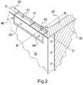
- the returns 35 and 37 are assembled via the bracket 40.
- the elastomeric seal 71 fills the gap between the return 35 and the return 37 and on the other hand, the space between the return 37 and the left side plate 31.
- the elastomer seal also serves to complete the seal between the bottom plate 30 and the front plate 32.
- the first two assembly areas 1) and 2) above form an edge of the trunk, while the area 3) is located on one of the sides of the trunk, in this case the upper face of the trunk.
- a first metal plate is flat and the second metal plate can be either a folded plate or a profile, that is to say a material which has been given a definite form.
- the folded plate can be L-shaped.
- the profile can for example be an angle iron, a tube of triangular section or a tube of square section.
- the fold zone of the second plate corresponds to one of the edges of the trunk.
- the diameter of the rivet rod is generally between 1 and 5 mm.
- the minimum distance between the axes of the rods of two neighboring rivets is generally at least equal to 2.5 times the diameter of the rivet rod.
- the value of 2.5 is common in the field of riveting and is a good compromise between the amount of material and a satisfactory strength assembly.
- An operator can install a rivet with only access to one side of the plate, unlike a method of assembly using a bolt that requires the operator has access to both sides of the plate to ask the nut and the screw.
- the method of assembly by rivets thus offers better accessibility.
- an elastomer seal 71 of specific composition detailed below in contact with the field of the first plate and the fold zone of the second plate.
- the tightness already provided by the rivets is reinforced by the presence of the seal because it prevents any infiltration of electrolyte into the area of overlap, that is to say between the face of the first plate facing outwards. of the chest and the face of the second plate turned towards the inside of the chest. This therefore avoids any further degradation of the rivet in case of electrolyte leakage. Sealing is ensured by the mere presence of rivets. The presence of the seal is optional.
- the seal is placed once the riveting operation is complete. It is not compressed by the action of rivets. It does not deform, as it would be if it were compressed by a nut and a screw.
- the second metal plate is a profile such as a bracket 40 having two L-shaped branches.
- the back 37 of the front plate is assembled to the horizontal branch of the bracket using a series of rivets, of which only one 82 is shown figure 4 according to the method described above.
- the rivet 82 has a head 82a, a rod 82b and a bulb 82c which corresponds to the portion of the rod deformed at the assembly out of the hole.
- a third metal plate 31 is assembled to the vertical branch of the angle using a series of rivets, of which only one 84 is shown. figure 4 according to the same method.
- the rivet 84 has a head 84a, a rod 84b and a bulb 84c.
- the first metal plate 37 is thus assembled to the third metal plate 31 by means of a profile having the shape of an angle 40.
- an elastomeric seal so that it is in contact with the return field 37, the field of the third plate 31 and the edge of the angle 40, that is to say the junction point of the two branches of the angle.
- FIG. 5 represents a view along the axis CC 'of the figure 2 .
- the first plate is formed by the return 35 of the plate 31 and the second plate is constituted by the horizontal branch of the bracket 40.
- the return 35 is assembled to the horizontal branch of the angle using a rivet 81 according to the same method as that described above.
- the rivet 81 has a head 81a, a rod 81b and a bulb 81c.
- a third metal plate 37 constituted by the return of the plate of the front face 32 can also be assembled to the horizontal branch of the angle using a rivet 82.
- An elastomer seal 71 is then placed in contact with the field of the return 35, the return field 37 and the surface of the horizontal branch of the bracket 40 turned towards the inside of the box.
- the elastomeric seal is disposed in continuity with the overlap zone, in continuous contact with the first and the second plate.
- This may correspond to an embodiment as represented in Figures 3, 4 and 5 wherein the seal is disposed in contact with the field of the first plate and in contact with the face of the second plate facing the interior of the box, that is to say in contact with the electrolyte. It is also possible to arrange the seal between the surface of the first plate not exposed to the electrolyte and the surface of the second plate exposed to the electrolyte. The seal is then maintained in compression between the two plates.
- This embodiment is, however, less preferred than that illustrated in Figures 3, 4 and 5 because the seal is then subjected to a compressive force under the effect of riveting, which may damage it.
- an elastomeric seal comprising a material selected from a butyl rubber, a terpolymer obtained by polymerization of ethylene-propylene-diene monomers (EPDM) and a nitrile rubber makes it possible to limit the absorption of liquid electrolyte through the seal.
- EPDM ethylene-propylene-diene monomers
- butyl rubber any copolymer of isobutylene and isoprene.
- the copolymerization solvent between isobutylene and isoprene is methyl chloride CH 3 Cl and the reaction is catalyzed by a solution of aluminum chloride AlCl 3 in the same solvent.
- the polymerization involves 98% isobutylene with 2% isoprene.
- the use of a butyl rubber makes it possible to avoid the degradation of the joint by the electrolyte.
- the seal comprises at least 10% by weight of a copolymer of isobutylene with isoprene.
- the seal comprises less than 50% by weight of a copolymer of isobutylene with isoprene, preferably 15 to 25% by weight.
- This seal is commonly used to achieve the sealing of windows in the automotive field.
- a second seal comprising a butyl rubber and particularly suitable for the invention is commercially available from Sika under the trade name SikaLastomer®-710.
- the elastomeric seal comprises an ethylene-propylene-diene monomer terpolymer (EPDM) which is obtained by copolymerizing ethylene in varying proportions (the terpolymer generally contains from 60 to 85% ethylene units), the propylene and a nonconjugated diene at a low level.
- EPDM ethylene-propylene-diene monomer terpolymer
- the percentage of ethylene-propylene-diene monomer terpolymer (EPDM) in the seal is greater than 50%.
- the elastomeric seal comprises a nitrile rubber.
- nitrile rubber any butadiene-acrylonitrile copolymer whose formula is given below:
- the copolymer is synthesized by radical copolymerization in emulsion of butadiene with acrylonitrile.
- the acrylonitrile level is variable and is between 15 and 51%.
- the percentage of butadiene-acrylonitrile copolymer in the joint material is greater than 50%.
- the gasket is preformed, that is to say it has a predetermined shape before application to the assembly zone, this shape having been conferred by the gasket manufacturing process, for example during an extrusion.
- Tests were conducted to evaluate the resistance of several seal materials to the corrosivity of the electrolyte.
- Several joints made of materials of different chemical compositions were applied to a stainless steel plate previously cleaned with acetone. The seal was dried overnight at 70 ° C. The plate was weighed and then immersed in a concentrated solution of potassium hydroxide at pH> 14 and aging at 70 ° C. After one, two, four and eight weeks, the plate was rinsed, dried overnight at 70 ° C and then exposed for two hours at room temperature. Then, the mass variation of the joints was measured. The table below summarizes the test results.
- the verification of the maintenance of the structural integrity of the trunk was made by visual inspection and by measuring the electrical continuity between different points of the trunk and by checking the proper modes of resonance of the trunk.
- the comparison between the values of electrical continuity measured before application of the vibrations and after application of the vibrations indicates small differences, which shows that the box keeps a good structural resistance even after being subjected to strong vibrations.
- the chest according to the invention thus passes the standardized tests of vibration resistance. It can be mounted on the platform of a motorized vehicle, such as a train, without knowing any leakage.
Landscapes
- Chemical & Material Sciences (AREA)
- General Chemical & Material Sciences (AREA)
- Electrochemistry (AREA)
- Chemical Kinetics & Catalysis (AREA)
- Engineering & Computer Science (AREA)
- Inorganic Chemistry (AREA)
- Theoretical Computer Science (AREA)
- Physics & Mathematics (AREA)
- Mechanical Engineering (AREA)
- General Physics & Mathematics (AREA)
- General Engineering & Computer Science (AREA)
- Geometry (AREA)
- Evolutionary Computation (AREA)
- Computer Hardware Design (AREA)
- Sealing Battery Cases Or Jackets (AREA)
- Architecture (AREA)
- Software Systems (AREA)
Claims (14)
- Abgedichtetes Gehäuse (1) für Batterien (51, 52, 53, 54) mit alkalischem Elektrolyten, das eine Anordnung von Metallplatten (30, 31, 32, 33, 34) umfasst, wobei :- eine erste Metallplatte (32), in einem Überlappungsbereich, von einer Reihe von Löchern durchbohrt ist;- eine zweite Metallplatte (30) von einer Reihe von Löchern durchbohrt ist, die den Löchern der ersten Metallplatte im Überlappungsbereich gegenüberliegend angeordnet sind;- die beiden Platten im Überlappungsbereich überlappen und in diesem Bereich durch strukturelle Blindnieten zusammengefügt sind, von denen jede einen Kopf (85a), einen Schaft (85b) und einen Kolben (85c) umfasst;- Kopf und Kolben der strukturellen Blindnieten auf einer Oberfläche jeder Platte anliegen, die sich über die Oberfläche jedes Loches hinaus erstreckt;- der Schaft (85b) der strukturellen Blindnieten so verformt ist, dass er im Wesentlichen das gesamte Volumen der Löcher der ersten und zweiten Platte abdichtend einnimmt.
- Gehäuse nach Anspruch 1, umfassend eine elastomere Dichtung (71), die ein Material umfasst, das ausgewählt ist aus einem Butylkautschuk, einem Ethylen-Propylen-Dien-Terpolymer und einem Nitrilkautschuk, wobei die Dichtung, in Fortsetzung des Überlappungsbereichs, in kontinuierlichem Kontakt mit der ersten (32) und der zweiten (30) Platte angeordnet ist, um somit die Abdichtung des Gehäuses zu ergänzen.
- Gehäuse nach Anspruch 2, dadurch gekennzeichnet dass die erste Platte (32) im Überlappungsbereich zum Inneren des Gehäuses hin angeordnet ist und mit dem alkalischen Elektrolyten in Kontakt gebracht wird, und die zweite Platte (30) im Überlappungsbereich zum Äußeren des Gehäuses hin angeordnet ist und mit dem alkalischen Elektrolyten in diesem Bereich nicht in Kontakt gebracht wird, dass die Reihe der Löcher der ersten Platte im Überlappungsbereich einem Feld der ersten Platte benachbart angeordnet ist, und dass die elastomere Dichtung das Feld abdeckt.
- Gehäuse nach Ansprüchen 1, 2 oder 3, dadurch gekennzeichnet dass jede Metallplatte ausgewählt ist aus:- einer ebenen Platte;- einer gefalzten Platte;- einer Profilplatte.
- Gehäuse nach einem der vorangehenden Ansprüche, wobei die Anordnung von Platten (30, 31, 32, 33, 34) ausschließlich mithilfe von strukturellen Blindnieten erhalten wird.
- Gehäuse nach einem der vorangehenden Ansprüche, wobei die Anordnung von Platten (30, 31, 32, 33, 34) frei von Schweißnahten ist.
- Gehäuse nach einem der Ansprüche 2 bis 6, wobei die elastomere Dichtung einen Butylkautschuk umfasst, der ein Isobutylen-/ und ein Isopren-Copolymer ist.
- Gehäuse nach einem der Ansprüche 2 bis 6, wobei die elastomere Dichtung einen Nitrilkautschuk umfasst, der ein Butadien-/ und ein Acrylnitril-Copolymer ist.
- Gehäuse nach einem der Ansprüche 2 bis 8, wobei die Dichtung vorgeformt ist.
- Gehäuse nach einem der Ansprüche 2 bis 8, wobei die Dichtung am Rande des Überlappungsbereichs angeordnet ist und nicht durch die Wirkung der strukturellen Blindnieten komprimiert wird.
- Gehäuse nach einem der Ansprüche 2 bis 9, wobei die Dichtung im Überlappungsbereich zwischen der ersten und der zweiten Platte angeordnet ist und durch die Wirkung der strukturellen Blindnieten komprimiert wird.
- Verfahren zur Herstellung eines abgedichteten Gehäuses (1), für Batterien mit alkalischem Elektrolyten (51, 52, 53, 54), umfassend eine Anordnung von Platten (30, 31, 32, 33, 34), wobei das Verfahren folgende Schritte umfasst:- Bereitstellen einer ersten Metallplatte (32), die in einem Überlappungsbereich von einer Reihe von Löchern durchbohrt ist;- Bereitstellen einer zweiten Metallplatte (30), die von einer Reihe von Löchern durchbohrt ist, die dazu vorgesehen sind den Löchern der ersten Metallplatte im Überlappungsbereich gegenüberliegend angeordnet zu sein, wobei beide Platten dazu bestimmt sind, im Überlappungsbereich zu überlappen;- Anordnung der beiden Platten im Überlappungsbereich, mithilfe von strukturellen Blindnieten, von denen jede einen Kopf (85a), einen Schaft (85b) und einen Kolben (85c) umfasst, so dass Kopf und Kolben der strukturellen Blindnieten auf einer Oberfläche jeder Platte anliegen, die sich über die Oberfläche jedes Loches hinaus erstreckt, und dass der Schaft der strukturellen Blindnieten so verformt ist, dass er im Wesentlichen das gesamte Volumen der Löcher der ersten und zweiten Platte abdichtend einnimmt.
- Verfahren nach Anspruch 12, umfassend eine elastomere Dichtung (71), die ein Material umfasst, das ausgewählt ist aus einem Butylkautschuk, einem Ethylen-Propylen-Dien-Terpolymer und einem Nitrilkautschuk, wobei die Dichtung, in Fortsetzung des Überlappungsbereichs, in kontinuierlichem Kontakt mit der ersten und der zweiten Platte angeordnet ist, um somit die Abdichtung des Gehäuses zu ergänzen.
- Verfahren nach Anspruch 12, wobei jede Metallplatte ausgewählt ist aus:- einer ebenen Platte;- einer gefalzten Platte;- einer Profilplatte.
Applications Claiming Priority (2)
| Application Number | Priority Date | Filing Date | Title |
|---|---|---|---|
| FR1259680A FR2996683B1 (fr) | 2012-10-10 | 2012-10-10 | Coffre etanche pour batteries alcalines |
| PCT/EP2013/071086 WO2014056998A1 (fr) | 2012-10-10 | 2013-10-09 | Coffre etanche pour batteries alcalines |
Publications (2)
| Publication Number | Publication Date |
|---|---|
| EP2907176A1 EP2907176A1 (de) | 2015-08-19 |
| EP2907176B1 true EP2907176B1 (de) | 2018-04-04 |
Family
ID=47666241
Family Applications (1)
| Application Number | Title | Priority Date | Filing Date |
|---|---|---|---|
| EP13773814.2A Active EP2907176B1 (de) | 2012-10-10 | 2013-10-09 | Abgedichtetes gehäuse für alkalibatterien |
Country Status (5)
| Country | Link |
|---|---|
| US (1) | US10566586B2 (de) |
| EP (1) | EP2907176B1 (de) |
| CN (1) | CN104781950B (de) |
| FR (1) | FR2996683B1 (de) |
| WO (1) | WO2014056998A1 (de) |
Families Citing this family (6)
| Publication number | Priority date | Publication date | Assignee | Title |
|---|---|---|---|---|
| CN104124408B (zh) * | 2014-06-30 | 2016-08-17 | 昆山一邦泰汽车零部件制造有限公司 | 一种密封电池盒 |
| FR3050726B1 (fr) | 2016-04-29 | 2018-05-25 | Alstom Transport Technologies | Coffre pour equipement electrique et vehicule ferroviaire comprenant un tel coffre |
| CN106848132B (zh) * | 2016-12-29 | 2018-06-26 | 上海思致汽车工程技术有限公司 | 一种模块式电池包外壳 |
| EP3419080B1 (de) * | 2017-06-19 | 2020-10-14 | DURA Operating, LLC | Batterieträgerrahmen und verfahren zu dessen herstellung |
| FR3085869B1 (fr) * | 2018-09-19 | 2020-09-11 | Psa Automobiles Sa | Procede d’assemblage de deux toles se chevauchant partiellement avec triple etancheite |
| CN110832666A (zh) * | 2018-11-23 | 2020-02-21 | 深圳市大疆创新科技有限公司 | 电池外壳、电池组件、电子装置及电池的组装方法 |
Family Cites Families (8)
| Publication number | Priority date | Publication date | Assignee | Title |
|---|---|---|---|---|
| US6395417B1 (en) * | 1999-10-27 | 2002-05-28 | Douglas Frazier | Spill containment system with a flexible corrosion-resistant liner |
| KR100778511B1 (ko) * | 2006-09-11 | 2007-11-22 | 삼성에스디아이 주식회사 | 이차 전지 모듈 |
| US7859418B2 (en) * | 2008-07-15 | 2010-12-28 | Morton Greene | Apparatus, system and method for sensing to locate persons in a building in the event of a disaster |
| US20100136402A1 (en) * | 2009-04-22 | 2010-06-03 | Tesla Motors, Inc. | Sealed battery enclosure |
| FR2959606B1 (fr) | 2010-04-28 | 2012-12-28 | Michelin Soc Tech | Coffre a batterie compartimente pour vehicule electrique ou hybride. |
| CN201975440U (zh) * | 2011-02-10 | 2011-09-14 | 上海内燃机研究所 | 车载电池盒 |
| CN202058811U (zh) * | 2011-03-21 | 2011-11-30 | 深圳市沃特玛电池有限公司 | 一种电池组 |
| JP5711593B2 (ja) * | 2011-04-12 | 2015-05-07 | ポップリベット・ファスナー株式会社 | ブラインドリベット及びその締結方法 |
-
2012
- 2012-10-10 FR FR1259680A patent/FR2996683B1/fr not_active Expired - Fee Related
-
2013
- 2013-10-09 EP EP13773814.2A patent/EP2907176B1/de active Active
- 2013-10-09 WO PCT/EP2013/071086 patent/WO2014056998A1/fr not_active Ceased
- 2013-10-09 US US14/434,478 patent/US10566586B2/en active Active
- 2013-10-09 CN CN201380059650.7A patent/CN104781950B/zh not_active Expired - Fee Related
Also Published As
| Publication number | Publication date |
|---|---|
| CN104781950A (zh) | 2015-07-15 |
| EP2907176A1 (de) | 2015-08-19 |
| CN104781950B (zh) | 2017-08-25 |
| FR2996683A1 (fr) | 2014-04-11 |
| US20150295213A1 (en) | 2015-10-15 |
| US10566586B2 (en) | 2020-02-18 |
| WO2014056998A1 (fr) | 2014-04-17 |
| FR2996683B1 (fr) | 2015-01-02 |
Similar Documents
| Publication | Publication Date | Title |
|---|---|---|
| EP2488403B1 (de) | Fahrzeugstruktur mit einer batterie | |
| WO2014056998A1 (fr) | Coffre etanche pour batteries alcalines | |
| CA2044303C (fr) | Emballages thermosoudables pour batteries au lithium | |
| EP3130020B1 (de) | Elektrochemischer lithium-ionen-akku mit direkt an die elektrodenanordnung angeschlossenem anschluss und zugehöriges herstellungsverfahren | |
| EP0948064B1 (de) | Prismatische aufladbare oder primäre Zelle mit steifem und zusammendrückendem Halter | |
| EP3364479B1 (de) | Batterie, insbesondere knopfbatterie, und ihr herstellungsverfahren | |
| CN101821874A (zh) | 密封型电池 | |
| EP3991238A1 (de) | Elektrizitätsspeicherbatterie und fahrzeug | |
| WO2013160820A1 (fr) | Traversee formant borne pour accumulateur electrochimique au lithium et accumulateur associe | |
| JP2009134986A (ja) | 密閉型電池 | |
| EP3329527B1 (de) | Lithiumspeicherbatterie mit integriertem schutzschalter für verbesserte bediensicherheit | |
| FR3039709A1 (fr) | Accumulateur au lithium a surete de fonctionnement amelioree par un dispositif coupe-circuit integre | |
| EP3985769A1 (de) | Batteriemodul mit stapel von weich verpackten akkumulatoren, die in festen halterungen zwischen ihnen durch knappen oder klippen und stützklemmen in druckkontakt mit den akkumulatorklemmen gehäuset werden. | |
| EP2532038B1 (de) | Elektrochemischer akkumulator mit gehäuse mit mindestens einem polyaryletherketon (paek), zugehörige folie und verfahren | |
| BE1005392A3 (fr) | Pile electrochimique aqueuse. | |
| EP3021383B1 (de) | Verfahren zum wasserdichten abdichten einer öffnung eines akkumulatorgehäuses, und durch dieses verfahren abgedichtetes gehäuse | |
| EP3888154A1 (de) | Batteriegehäuse und modulares batteriesystem | |
| EP4320003B1 (de) | Gehäuse für eine batterie eines landfahrzeugs | |
| FR2465321A1 (fr) | Element galvanique comprenant un carter ferme de maniere etanche et procede servant a sa fabrication | |
| EP2826082B1 (de) | Leichtgewichtiger elektrochemischer speicher auf li-ionen-basis | |
| EP3510652B1 (de) | Durchführung zur bildung einer klemme für eine elektrochemische metall-ionen-batterie und entsprechende batterie | |
| EP3853918B1 (de) | Verfahren zum zusammenbau zweier teilweise überlappender bleche mit einer dreifachdichtung | |
| FR3162924A1 (fr) | Module de batterie comprenant une entretoise | |
| EP3155270B1 (de) | Mittel zum verkeilen eines elektrochemischen generators in einer position in einer batterie | |
| FR3166683A1 (fr) | Panneau d’explosion avec un materiau isolant thermiquement et son procede de fabrication |
Legal Events
| Date | Code | Title | Description |
|---|---|---|---|
| PUAI | Public reference made under article 153(3) epc to a published international application that has entered the european phase |
Free format text: ORIGINAL CODE: 0009012 |
|
| 17P | Request for examination filed |
Effective date: 20150506 |
|
| AK | Designated contracting states |
Kind code of ref document: A1 Designated state(s): AL AT BE BG CH CY CZ DE DK EE ES FI FR GB GR HR HU IE IS IT LI LT LU LV MC MK MT NL NO PL PT RO RS SE SI SK SM TR |
|
| AX | Request for extension of the european patent |
Extension state: BA ME |
|
| DAX | Request for extension of the european patent (deleted) | ||
| 17Q | First examination report despatched |
Effective date: 20161201 |
|
| GRAP | Despatch of communication of intention to grant a patent |
Free format text: ORIGINAL CODE: EPIDOSNIGR1 |
|
| INTG | Intention to grant announced |
Effective date: 20171009 |
|
| GRAJ | Information related to disapproval of communication of intention to grant by the applicant or resumption of examination proceedings by the epo deleted |
Free format text: ORIGINAL CODE: EPIDOSDIGR1 |
|
| GRAR | Information related to intention to grant a patent recorded |
Free format text: ORIGINAL CODE: EPIDOSNIGR71 |
|
| GRAS | Grant fee paid |
Free format text: ORIGINAL CODE: EPIDOSNIGR3 |
|
| INTC | Intention to grant announced (deleted) | ||
| GRAA | (expected) grant |
Free format text: ORIGINAL CODE: 0009210 |
|
| AK | Designated contracting states |
Kind code of ref document: B1 Designated state(s): AL AT BE BG CH CY CZ DE DK EE ES FI FR GB GR HR HU IE IS IT LI LT LU LV MC MK MT NL NO PL PT RO RS SE SI SK SM TR |
|
| INTG | Intention to grant announced |
Effective date: 20180227 |
|
| REG | Reference to a national code |
Ref country code: GB Ref legal event code: FG4D Free format text: NOT ENGLISH |
|
| REG | Reference to a national code |
Ref country code: CH Ref legal event code: EP |
|
| REG | Reference to a national code |
Ref country code: AT Ref legal event code: REF Ref document number: 986511 Country of ref document: AT Kind code of ref document: T Effective date: 20180415 |
|
| REG | Reference to a national code |
Ref country code: DE Ref legal event code: R096 Ref document number: 602013035434 Country of ref document: DE |
|
| REG | Reference to a national code |
Ref country code: IE Ref legal event code: FG4D Free format text: LANGUAGE OF EP DOCUMENT: FRENCH |
|
| REG | Reference to a national code |
Ref country code: NL Ref legal event code: MP Effective date: 20180404 |
|
| REG | Reference to a national code |
Ref country code: LT Ref legal event code: MG4D |
|
| PG25 | Lapsed in a contracting state [announced via postgrant information from national office to epo] |
Ref country code: NL Free format text: LAPSE BECAUSE OF FAILURE TO SUBMIT A TRANSLATION OF THE DESCRIPTION OR TO PAY THE FEE WITHIN THE PRESCRIBED TIME-LIMIT Effective date: 20180404 |
|
| REG | Reference to a national code |
Ref country code: FR Ref legal event code: PLFP Year of fee payment: 6 |
|
| PG25 | Lapsed in a contracting state [announced via postgrant information from national office to epo] |
Ref country code: LT Free format text: LAPSE BECAUSE OF FAILURE TO SUBMIT A TRANSLATION OF THE DESCRIPTION OR TO PAY THE FEE WITHIN THE PRESCRIBED TIME-LIMIT Effective date: 20180404 Ref country code: PL Free format text: LAPSE BECAUSE OF FAILURE TO SUBMIT A TRANSLATION OF THE DESCRIPTION OR TO PAY THE FEE WITHIN THE PRESCRIBED TIME-LIMIT Effective date: 20180404 Ref country code: BG Free format text: LAPSE BECAUSE OF FAILURE TO SUBMIT A TRANSLATION OF THE DESCRIPTION OR TO PAY THE FEE WITHIN THE PRESCRIBED TIME-LIMIT Effective date: 20180704 Ref country code: FI Free format text: LAPSE BECAUSE OF FAILURE TO SUBMIT A TRANSLATION OF THE DESCRIPTION OR TO PAY THE FEE WITHIN THE PRESCRIBED TIME-LIMIT Effective date: 20180404 Ref country code: NO Free format text: LAPSE BECAUSE OF FAILURE TO SUBMIT A TRANSLATION OF THE DESCRIPTION OR TO PAY THE FEE WITHIN THE PRESCRIBED TIME-LIMIT Effective date: 20180704 Ref country code: AL Free format text: LAPSE BECAUSE OF FAILURE TO SUBMIT A TRANSLATION OF THE DESCRIPTION OR TO PAY THE FEE WITHIN THE PRESCRIBED TIME-LIMIT Effective date: 20180404 Ref country code: SE Free format text: LAPSE BECAUSE OF FAILURE TO SUBMIT A TRANSLATION OF THE DESCRIPTION OR TO PAY THE FEE WITHIN THE PRESCRIBED TIME-LIMIT Effective date: 20180404 Ref country code: ES Free format text: LAPSE BECAUSE OF FAILURE TO SUBMIT A TRANSLATION OF THE DESCRIPTION OR TO PAY THE FEE WITHIN THE PRESCRIBED TIME-LIMIT Effective date: 20180404 |
|
| PG25 | Lapsed in a contracting state [announced via postgrant information from national office to epo] |
Ref country code: GR Free format text: LAPSE BECAUSE OF FAILURE TO SUBMIT A TRANSLATION OF THE DESCRIPTION OR TO PAY THE FEE WITHIN THE PRESCRIBED TIME-LIMIT Effective date: 20180705 Ref country code: HR Free format text: LAPSE BECAUSE OF FAILURE TO SUBMIT A TRANSLATION OF THE DESCRIPTION OR TO PAY THE FEE WITHIN THE PRESCRIBED TIME-LIMIT Effective date: 20180404 Ref country code: RS Free format text: LAPSE BECAUSE OF FAILURE TO SUBMIT A TRANSLATION OF THE DESCRIPTION OR TO PAY THE FEE WITHIN THE PRESCRIBED TIME-LIMIT Effective date: 20180404 Ref country code: LV Free format text: LAPSE BECAUSE OF FAILURE TO SUBMIT A TRANSLATION OF THE DESCRIPTION OR TO PAY THE FEE WITHIN THE PRESCRIBED TIME-LIMIT Effective date: 20180404 |
|
| REG | Reference to a national code |
Ref country code: AT Ref legal event code: MK05 Ref document number: 986511 Country of ref document: AT Kind code of ref document: T Effective date: 20180404 |
|
| PG25 | Lapsed in a contracting state [announced via postgrant information from national office to epo] |
Ref country code: PT Free format text: LAPSE BECAUSE OF FAILURE TO SUBMIT A TRANSLATION OF THE DESCRIPTION OR TO PAY THE FEE WITHIN THE PRESCRIBED TIME-LIMIT Effective date: 20180806 |
|
| REG | Reference to a national code |
Ref country code: DE Ref legal event code: R097 Ref document number: 602013035434 Country of ref document: DE |
|
| PG25 | Lapsed in a contracting state [announced via postgrant information from national office to epo] |
Ref country code: DK Free format text: LAPSE BECAUSE OF FAILURE TO SUBMIT A TRANSLATION OF THE DESCRIPTION OR TO PAY THE FEE WITHIN THE PRESCRIBED TIME-LIMIT Effective date: 20180404 Ref country code: EE Free format text: LAPSE BECAUSE OF FAILURE TO SUBMIT A TRANSLATION OF THE DESCRIPTION OR TO PAY THE FEE WITHIN THE PRESCRIBED TIME-LIMIT Effective date: 20180404 Ref country code: AT Free format text: LAPSE BECAUSE OF FAILURE TO SUBMIT A TRANSLATION OF THE DESCRIPTION OR TO PAY THE FEE WITHIN THE PRESCRIBED TIME-LIMIT Effective date: 20180404 Ref country code: RO Free format text: LAPSE BECAUSE OF FAILURE TO SUBMIT A TRANSLATION OF THE DESCRIPTION OR TO PAY THE FEE WITHIN THE PRESCRIBED TIME-LIMIT Effective date: 20180404 Ref country code: SK Free format text: LAPSE BECAUSE OF FAILURE TO SUBMIT A TRANSLATION OF THE DESCRIPTION OR TO PAY THE FEE WITHIN THE PRESCRIBED TIME-LIMIT Effective date: 20180404 Ref country code: CZ Free format text: LAPSE BECAUSE OF FAILURE TO SUBMIT A TRANSLATION OF THE DESCRIPTION OR TO PAY THE FEE WITHIN THE PRESCRIBED TIME-LIMIT Effective date: 20180404 |
|
| PLBE | No opposition filed within time limit |
Free format text: ORIGINAL CODE: 0009261 |
|
| STAA | Information on the status of an ep patent application or granted ep patent |
Free format text: STATUS: NO OPPOSITION FILED WITHIN TIME LIMIT |
|
| PG25 | Lapsed in a contracting state [announced via postgrant information from national office to epo] |
Ref country code: SM Free format text: LAPSE BECAUSE OF FAILURE TO SUBMIT A TRANSLATION OF THE DESCRIPTION OR TO PAY THE FEE WITHIN THE PRESCRIBED TIME-LIMIT Effective date: 20180404 Ref country code: IT Free format text: LAPSE BECAUSE OF FAILURE TO SUBMIT A TRANSLATION OF THE DESCRIPTION OR TO PAY THE FEE WITHIN THE PRESCRIBED TIME-LIMIT Effective date: 20180404 |
|
| 26N | No opposition filed |
Effective date: 20190107 |
|
| PG25 | Lapsed in a contracting state [announced via postgrant information from national office to epo] |
Ref country code: SI Free format text: LAPSE BECAUSE OF FAILURE TO SUBMIT A TRANSLATION OF THE DESCRIPTION OR TO PAY THE FEE WITHIN THE PRESCRIBED TIME-LIMIT Effective date: 20180404 |
|
| REG | Reference to a national code |
Ref country code: CH Ref legal event code: PL |
|
| REG | Reference to a national code |
Ref country code: BE Ref legal event code: MM Effective date: 20181031 |
|
| PG25 | Lapsed in a contracting state [announced via postgrant information from national office to epo] |
Ref country code: MC Free format text: LAPSE BECAUSE OF FAILURE TO SUBMIT A TRANSLATION OF THE DESCRIPTION OR TO PAY THE FEE WITHIN THE PRESCRIBED TIME-LIMIT Effective date: 20180404 Ref country code: LU Free format text: LAPSE BECAUSE OF NON-PAYMENT OF DUE FEES Effective date: 20181009 |
|
| REG | Reference to a national code |
Ref country code: IE Ref legal event code: MM4A |
|
| PG25 | Lapsed in a contracting state [announced via postgrant information from national office to epo] |
Ref country code: BE Free format text: LAPSE BECAUSE OF NON-PAYMENT OF DUE FEES Effective date: 20181031 Ref country code: LI Free format text: LAPSE BECAUSE OF NON-PAYMENT OF DUE FEES Effective date: 20181031 Ref country code: CH Free format text: LAPSE BECAUSE OF NON-PAYMENT OF DUE FEES Effective date: 20181031 |
|
| PG25 | Lapsed in a contracting state [announced via postgrant information from national office to epo] |
Ref country code: IE Free format text: LAPSE BECAUSE OF NON-PAYMENT OF DUE FEES Effective date: 20181009 |
|
| PG25 | Lapsed in a contracting state [announced via postgrant information from national office to epo] |
Ref country code: MT Free format text: LAPSE BECAUSE OF FAILURE TO SUBMIT A TRANSLATION OF THE DESCRIPTION OR TO PAY THE FEE WITHIN THE PRESCRIBED TIME-LIMIT Effective date: 20180404 |
|
| PG25 | Lapsed in a contracting state [announced via postgrant information from national office to epo] |
Ref country code: TR Free format text: LAPSE BECAUSE OF FAILURE TO SUBMIT A TRANSLATION OF THE DESCRIPTION OR TO PAY THE FEE WITHIN THE PRESCRIBED TIME-LIMIT Effective date: 20180404 |
|
| PG25 | Lapsed in a contracting state [announced via postgrant information from national office to epo] |
Ref country code: MK Free format text: LAPSE BECAUSE OF NON-PAYMENT OF DUE FEES Effective date: 20180404 Ref country code: CY Free format text: LAPSE BECAUSE OF FAILURE TO SUBMIT A TRANSLATION OF THE DESCRIPTION OR TO PAY THE FEE WITHIN THE PRESCRIBED TIME-LIMIT Effective date: 20180404 Ref country code: HU Free format text: LAPSE BECAUSE OF FAILURE TO SUBMIT A TRANSLATION OF THE DESCRIPTION OR TO PAY THE FEE WITHIN THE PRESCRIBED TIME-LIMIT; INVALID AB INITIO Effective date: 20131009 |
|
| PG25 | Lapsed in a contracting state [announced via postgrant information from national office to epo] |
Ref country code: IS Free format text: LAPSE BECAUSE OF FAILURE TO SUBMIT A TRANSLATION OF THE DESCRIPTION OR TO PAY THE FEE WITHIN THE PRESCRIBED TIME-LIMIT Effective date: 20180804 |
|
| REG | Reference to a national code |
Ref country code: DE Ref legal event code: R079 Ref document number: 602013035434 Country of ref document: DE Free format text: PREVIOUS MAIN CLASS: H01M0002100000 Ipc: H01M0050200000 |
|
| PGFP | Annual fee paid to national office [announced via postgrant information from national office to epo] |
Ref country code: GB Payment date: 20221130 Year of fee payment: 10 Ref country code: DE Payment date: 20221028 Year of fee payment: 10 |
|
| P01 | Opt-out of the competence of the unified patent court (upc) registered |
Effective date: 20230514 |
|
| REG | Reference to a national code |
Ref country code: DE Ref legal event code: R119 Ref document number: 602013035434 Country of ref document: DE |
|
| GBPC | Gb: european patent ceased through non-payment of renewal fee |
Effective date: 20231009 |
|
| PG25 | Lapsed in a contracting state [announced via postgrant information from national office to epo] |
Ref country code: GB Free format text: LAPSE BECAUSE OF NON-PAYMENT OF DUE FEES Effective date: 20231009 |
|
| PG25 | Lapsed in a contracting state [announced via postgrant information from national office to epo] |
Ref country code: GB Free format text: LAPSE BECAUSE OF NON-PAYMENT OF DUE FEES Effective date: 20231009 Ref country code: DE Free format text: LAPSE BECAUSE OF NON-PAYMENT OF DUE FEES Effective date: 20240501 |
|
| PGFP | Annual fee paid to national office [announced via postgrant information from national office to epo] |
Ref country code: FR Payment date: 20241031 Year of fee payment: 12 |