EP2906903B1 - An apparatus and method for carrying and retrieval of a grenade - Google Patents
An apparatus and method for carrying and retrieval of a grenade Download PDFInfo
- Publication number
- EP2906903B1 EP2906903B1 EP13783405.7A EP13783405A EP2906903B1 EP 2906903 B1 EP2906903 B1 EP 2906903B1 EP 13783405 A EP13783405 A EP 13783405A EP 2906903 B1 EP2906903 B1 EP 2906903B1
- Authority
- EP
- European Patent Office
- Prior art keywords
- grenade
- top cover
- envelope
- spring
- buttons
- Prior art date
- Legal status (The legal status is an assumption and is not a legal conclusion. Google has not performed a legal analysis and makes no representation as to the accuracy of the status listed.)
- Active
Links
- 238000000034 method Methods 0.000 title description 3
- 230000001960 triggered effect Effects 0.000 claims description 4
- 210000003414 extremity Anatomy 0.000 description 13
- 239000000463 material Substances 0.000 description 5
- 210000003813 thumb Anatomy 0.000 description 5
- 239000002360 explosive Substances 0.000 description 3
- 230000000903 blocking effect Effects 0.000 description 2
- 210000003811 finger Anatomy 0.000 description 2
- 210000004247 hand Anatomy 0.000 description 2
- 239000000779 smoke Substances 0.000 description 2
- 230000003213 activating effect Effects 0.000 description 1
- 238000005452 bending Methods 0.000 description 1
- 238000013461 design Methods 0.000 description 1
- 238000004880 explosion Methods 0.000 description 1
- 239000012634 fragment Substances 0.000 description 1
- 238000003780 insertion Methods 0.000 description 1
- 230000037431 insertion Effects 0.000 description 1
- 239000002184 metal Substances 0.000 description 1
- 238000012986 modification Methods 0.000 description 1
- 230000004048 modification Effects 0.000 description 1
- 239000004033 plastic Substances 0.000 description 1
- 229920003023 plastic Polymers 0.000 description 1
- 230000001105 regulatory effect Effects 0.000 description 1
- 238000009958 sewing Methods 0.000 description 1
- 239000007779 soft material Substances 0.000 description 1
- 238000012549 training Methods 0.000 description 1
Images


Classifications
-
- A—HUMAN NECESSITIES
- A45—HAND OR TRAVELLING ARTICLES
- A45F—TRAVELLING OR CAMP EQUIPMENT: SACKS OR PACKS CARRIED ON THE BODY
- A45F5/00—Holders or carriers for hand articles; Holders or carriers for use while travelling or camping
- A45F5/02—Fastening articles to the garment
- A45F5/021—Fastening articles to the garment to the belt
-
- F—MECHANICAL ENGINEERING; LIGHTING; HEATING; WEAPONS; BLASTING
- F41—WEAPONS
- F41C—SMALLARMS, e.g. PISTOLS, RIFLES; ACCESSORIES THEREFOR
- F41C33/00—Means for wearing or carrying smallarms
- F41C33/02—Holsters, i.e. cases for pistols having means for being carried or worn, e.g. at the belt or under the arm
- F41C33/0272—Holsters, i.e. cases for pistols having means for being carried or worn, e.g. at the belt or under the arm having means for facilitating or accelerating the drawing of the small arm from the holster
-
- F—MECHANICAL ENGINEERING; LIGHTING; HEATING; WEAPONS; BLASTING
- F42—AMMUNITION; BLASTING
- F42B—EXPLOSIVE CHARGES, e.g. FOR BLASTING, FIREWORKS, AMMUNITION
- F42B39/00—Packaging or storage of ammunition or explosive charges; Safety features thereof; Cartridge belts or bags
- F42B39/02—Cartridge bags; Bandoleers
Description
- The subject matter relates generally to a retrieval envelope for carrying grenades and rapidly deploying the grenades.
- Grenades are explosive devices used by various personnel, such as law enforcement personnel or military officers, as a projectile to attack a target at a distance from a thrower. There are various types of grenades available, such as a fragment grenade, stun grenade, smoke grenade, incendiary grenade, etc. When used, grenades create an explosion which is intended to injure, emit a blaring noise, create smoke, and the like. Grenades may be thrown through a window or door of a crime location, such as a room in a house, and the like, to temporarily distract the occupants for a time sufficient to enable the law enforcement personnel to safely enter the location and neutralize any potential threats.
- The grenade is held in a throwing hand with the thumb placed over a grenade lever while a safety pin is pulled out of a safety pin hole. When the grenade is thrown, the grenade lever is released, a spring throws off the grenade lever and rotates the striker into the primer. The primer contains material similar to the head of a match. When struck, it ignites and sets fire to the fuse. The fuse burns at a controlled rate, providing a time delay, for example about four to five seconds. When the flame of the fuse reaches a detonator the grenade explodes.
- In order to separate the safety pin from the grenade, the user that throws the grenade is required to hold the grenade in one hand then pull the safety pin in the other hand, thus requiring the use of both hands in the handling of the grenade. A user that operates the grenade in both hands cannot operate the single weapon at the same time. During operation, removal of the grenade from a pouch and separating the safety pin from the grenade may be inconvenient, time consuming and intricate, factors which are critical to the success of situations requiring the use of grenades. A prior art apparatus for carrying a grenade can be found in
CH 11 335 A - The subject matter provides for an apparatus for quick release of a grenade in a single hand. The apparatus for carrying a grenade, comprising an envelope and a base connected to a bottom portion of the envelope for holding a grenade, a rear cover connected to the envelope for attaching said envelope to a vest of a user; a top cover connected to an upper portion of the envelope or the rear cover, said top cover secures the grenade from above when positioned in a downward position and is able to move upwards to an upward position; a spring connected on one end to the top cover and on another end to the envelope; at least one button connected to the envelope or to the rear cover, wherein pressing the at least one button releases the spring and causes the top cover to move to the upward position, wherein the at least one button is positioned above the base.
- The user of the apparatus can release the grenade from the apparatus while pressing the at least one button. The at least one button is located below the top cover and connected only to one of the envelope or the rear cover. The envelope is designed to enable the user to hold the grenade and the grenade lever in a single hand when pressing the at least one button and when releasing the grenade from the apparatus.
- The top cover is made of a rigid material. The top cover may surround an upper portion of the grenade, thereby securing explosives included in said upper portion. The top cover is connected to the envelope on an axis, wherein the top cover moves to the upward position in a rotational movement around the axis.
- The apparatus further comprising a protruding tooth for pushing the grenade away from the envelope when the top cover moves to the upward position, said protruding tooth protrudes from the top cover. The apparatus further comprising a soft inner lining connected to a bottom portion of the top cover being in contact with an upper portion of the grenade when the top cover is in the downward position. The spring is tensed when the top cover is in the downward position, wherein the spring is released when the at least one button is pressed, thereby the top cover moves to the upward position.
- The top cover may have protruding elements that are mounted on an upper end of the at least one button when the top cover is in the downward position and the spring is tensed, and wherein pressing the at least one button changes the location of the upper end of the at least one button, thereby enabling the protruding elements to move downwards and release the spring, such that the top cover is enabled to move to the upward position.
- The at least one button may be two buttons, wherein the protruding elements are positioned between the two buttons when the top cover is moved to the upward position, to prevent the two buttons to return to their original position. Pressing only one button of the two buttons fails to release the spring and fails to move the top cover to the upward position. The apparatus may also include a back spring connecting the two buttons, such that when the top cover is pushed downwards by the user, the back spring is tensed and the two buttons are distanced from each other. The two buttons may automatically be triggered by the back spring when the top cover is in the downward position.
- The apparatus may further comprise a mechanical track connected to the rear cover for connecting the apparatus to the garment, wherein the mechanical track enables connecting the apparatus to a plurality of locations on the garment. The apparatus may further comprise a drop shot hook used for hanging the apparatus on the vest without an adapter. The apparatus may further comprise a safety lever container connected to the envelope, said safety lever container is configured to secure and protect the grenade lever of the grenade.
- The apparatus may further comprise a ring holder connected to the envelope, said ring holder is configured to hold the pull ring, such that the pull ring is detached from the grenade responsive to removal of the grenade from the envelope. The ring holder may be a karabiner, wherein the karabiner is fastened to the pull ring. The ring holder may be connected to the envelope by a cord, such that the pull ring is detached from the grenade responsive to moving the grenade from the envelope at a distance longer than the cord's length. The rear cover may be connected to the vest at an angle versus the ground.
- Exemplary non-limited embodiments of the disclosed subject matter will be described, with reference to the following description of the embodiments, in conjunction with the figures. The figures are generally not shown to scale and any sizes are only meant to be exemplary and not necessarily limiting. Corresponding or like elements are optionally designated by the same numerals or letters.
-
Figure 1 shows a retrieval envelope holding a grenade, according to some exemplary embodiments of the subject matter; -
Figure 2 shows a ring holder connection to a safety pin, according to some exemplary embodiments of the subject matter; -
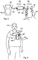
Figure 3 shows a release of a grenade from a retrieval envelope, according to some exemplary embodiments of the subject matter; -
Figure 4 shows a retrieval envelope attached to a garment on a person, according to some exemplary embodiments of the subject matter; and, -
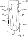
Figure 5 shows a side view of a retrieval envelope holding a grenade, according to some exemplary embodiments of the subject matter; -
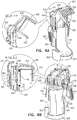
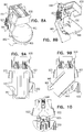
Figure 6A shows a front view of an apparatus for holding a grenade with a top cover in an upward position, according to some exemplary embodiments of the subject matter; -
Figure 6B shows a front view of an apparatus for holding a grenade with a top cover in a downward position, according to some exemplary embodiments of the subject matter; -
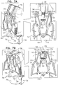
Figure 7A shows a rear view of an apparatus for holding a grenade with a top cover in an upward position, according to some exemplary embodiments of the subject matter; -
Figure 7B shows a rear view of an apparatus for holding a grenade with a top cover in a downward position, according to some exemplary embodiments of the subject matter; -
Figure 8A shows a front view of an apparatus for holding a sphere-like shaped grenade with a top cover in an upward position, according to some exemplary embodiments of the subject matter; -
Figure 8B shows a front view of an apparatus for holding a sphere-like shaped grenade with a top cover in a downward position, according to some exemplary embodiments of the subject matter; -
Figure 9A shows a rear view of an apparatus for holding a sphere-like shaped grenade with a top cover in an upward position, according to some exemplary embodiments of the subject matter; -
Figure 9B shows a rear view of an apparatus for holding a sphere-like shaped grenade with a top cover in a downward position, according to some exemplary embodiments of the subject matter; -
Figure 10 shows a rear view of an apparatus for holding a grenade, according to some exemplary embodiments of the subject matter; -
Figure 11 shows a vest having multiple positions for attaching the apparatus for holding a grenade, according to some exemplary embodiments of the subject matter; -
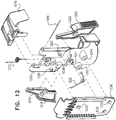
Figure 12 shows an exploded view of the apparatus for holding a grenade, according to some exemplary embodiments of the subject matter; and, -
Figure 13 shows an exploded view of the apparatus holding a spherical shaped grenade, according to some exemplary embodiments of the subject matter. - The present subject matter discloses a retrieval envelope for holding a grenade and a method of using the same, according to exemplary embodiments. A person, such as a law enforcement or military officer, inserts the grenade into the retrieval envelope, which partially envelopes the grenade while enabling rapid retrieval of the grenade. The grenade is secured in the retrieval envelope by a top cover, which is pushed down and locked into place over the top of the grenade. When the person wishes to use the grenade, he raises the top cover to enable removing the grenade. The top cover may be detached from the apparatus of the subject matter. Raising the top cover may be performed by activating a trigger, which releases a spring, which may also be a rubber band or a latch, raises the top cover. In some cases, the trigger comprises pressing at least two triggers simultaneously to prevent unwanted release of the top cover. The grenade may further be secured by one or more teeth or flaps which hold the grenade in the retrieval envelope, but are flexible enough to enable rapid and easy removal of the grenade from the retrieval envelope. The retrieval envelope enables the person to rapidly retrieve the grenade from the retrieval envelope and throw it rapidly and accurately at a desired target. The retrieval of the grenade may be done with a single hand and may be done by a person's weak hand, while a strong hand carries a primary weapon, such as an automatic rifle.
- The retrieval envelope comprises a safety lever container for containing the grenade lever and for maintaining the orientation of the grenade in the retrieval envelope. The retrieval envelope comprises a ring holder attached to a safety pin of the grenade. The ring holder enables the person to release and use the grenade rapidly and using a single hand. The ring holder holds onto the safety pin as the person moves the grenade away from the retrieval envelope, which releases the safety pin and permits throwing the grenade at a desired target. The retrieval envelope is attached to a garment, which may be a vest, a belt or any other apparel used by the person. The retrieval envelope may be attached to the garment by use of an attachment utensil, such as screws, sewing, buttons, or the like.
-
Figure 1 shows a retrieval envelope holding a grenade, according to some exemplary embodiments of the subject matter. Thegrenade 100 comprises asafety pin 110 and agrenade lever 105. Thesafety pin 110 is placed into apin hole 112 that keeps thegrenade lever 105 in place, preventing a release spring (not shown) from releasing thegrenade lever 105 and detonating thegrenade 100. Thegrenade 100 is placed intoretrieval envelope 120. - The
retrieval envelope 120 is designed to hold thegrenade 100 so the shape of theretrieval envelope 120 is configured for quick access and use. In some exemplary embodiments, theretrieval envelope 120 may compriseflaps 125, which secure thegrenade 100 in theretrieval envelope 120. Theretrieval envelope 120 may comprise asafety lever container 130, which holds thegrenade lever 105. Holding thegrenade lever 105 at thesafety lever container 130 prevents thegrenade 100 from disorienting when placed in theretrieval envelope 120. In some cases, thesafety lever container 130 may prevent thegrenade lever 105 from releasing in situations where thesafety pin 110 is prematurely removed or slips out of thesafety pin hole 112. - The
retrieval envelope 120 may also comprise ahook 150 to attach theretrieval envelope 120 to a garment such as a vest or a belt. Thehook 150 allows convenient transportation of one ormultiple retrieval envelopes 120 to and from the garment. - The
retrieval envelope 120 comprises acord 135, such as a rope or wire, which is connected to aring holder 140. The ring holder may be a karabiner comprising amobile limb 142. Thering holder 140 is attached to asafety pin ring 115. Once thering holder 140 is inserted into thesafety pin ring 115, thesafety pin ring 115 may be removed once the person using theretrieval envelope 120 pulls thegrenade 100 out and away from theretrieval envelope 120, so thesafety pin 110 is released from thesafety pin hole 112 by thering holder 140. - In some exemplary embodiments of the subject matter, a
rubber band 145 may be used to secure thegrenade 100 in theretrieval envelope 120. Therubber band 145 is placed around thegrenade 100 and theretrieval envelope 120 so thegrenade 100 may be easily removed from theretrieval envelope 120 using a single hand. In some embodiments, therubber band 145 may be attached to theretrieval envelope 120 so therubber band 145 does not fall to the ground and get lost when thegrenade 100 is removed from theretrieval envelope 120. Therubber band 145 is detached from thegrenade 100 when deploying thegrenade 100. -
Figure 2 shows a ring holder connection to a safety pin, according to exemplary embodiments of the subject matter. Thesafety pin 205 is inserted into asafety pin hole 203 located on agrenade lever 200 of agrenade 201. Thegrenade pin 205 comprises asafety pin ring 210. After thesafety pin ring 210 is pulled, thesafety pin 205 is removed out of thesafety pin hole 203, which enables thegrenade lever 200 to be released, igniting the fuse to detonate thegrenade 201. Aring holder 230, such as a karabiner, is inserted into thesafety pin ring 210. Thering holder 230 comprises a ring holder mechanism, such as amoveable limb 235, which can open and close to enable insertion of thering holder 230 into thesafety pin ring 210. Themoveable limb 235 is attached to the body of thering holder 230 by abolt 240, such as a screw, which enables themoveable limb 235 to open and close. Thering holder 230 is attached to acord 250, such as a rope or wire, which connects thering holder 230 to theretrieval envelope 120 offigure 1 . - Once the
ring holder 230 is inserted into thesafety pin ring 210, themoveable limb 235 is placed so thering holder 230 cannot be removed from thesafety pin ring 210 without opening themoveable limb 235. In some cases thering holder 230 may have a locking bolt (not shown), such as a locking karabiner, which has the locking bolt to enable locking themoveable limb 235 into place to prevent themoveable limb 235 from opening and releasing thesafety pin 205, for example, while thegrenade 201 is being removed from theretrieval envelope 120 offigure 1 . -
Figure 3 shows a method of releasing a grenade from a retrieval envelope, according to exemplary embodiments of the subject matter. A person carrying theretrieval envelope 340 uses ahand 300 to grab onto agrenade 310 located in theretrieval envelope 340. Thehand 300 grabs thegrenade 310 so that some fingers keep agrenade lever 315 from releasing, for example using athumb 305 to hold thegrenade lever 315 in place. Thethumb 305 is used to remove thegrenade 310 from theretrieval envelope 340 in a single fast motion. Thegrenade lever 315 is removed from asafety lever container 345 and controlled with thethumb 305 so thegrenade lever 315 does not release, preventing thegrenade 310 from detonating once asafety pin 325 is released. Thesafety pin 325 is located in asafety pin hole 327, which keeps thegrenade lever 315 locked and prevents thegrenade 310 from detonating until thesafety pin 325 is removed from thesafety pin hole 327. Thesafety pin 325 comprises asafety pin ring 320, attached to aring holder 330. Thering holder 330 is inserted into thesafety pin ring 320 so thering holder 330 and thesafety pin ring 320 are interlocked and cannot be detached. Thering holder 330 is attached to a cord 335, such as a rope or wire, which is connected to theretrieval envelope 340 at the opposite end of the cord 335. - To activate the
grenade 310, the person carrying theretrieval envelope 340 that holds thegrenade 310, grabs thegrenade 310 with the person'shand 300. The person places one of his/her fingers around thegrenade lever 315 to ensure that thegrenade 310 does not detonate in the person'shand 300. After removing thegrenade 310 from theretrieval envelope 340, the person moves thegrenade 310 away from theretrieval envelope 340, for example moving thegrenade 310 in aright direction 360 or moving theretrieval envelope 340 in aleft direction 370. Theretrieval envelope 340 enables the person to use only a single hand to remove thegrenade 310 from theretrieval envelope 340 and still have a second hand free for other requirements, such as carrying an automatic rifle. Theretrieval envelope 340 enables the person to rapidly remove thegrenade 310 from theretrieval envelope 340 and throw it rapidly with either a person's strong or weak hand. - As the
grenade 310 is moved further from theretrieval envelope 340, the cord 335 becomes tense and thering holder 330 at the end of the cord 335 pulls thesafety pin 325 out of thesafety pin hole 327. Theretrieval envelope 340, which sits on a garment of the person, such as a person's vest, creates tension in the cord 335, which enables thering holder 330 to remove thesafety pin 325 from thesafety pin hole 327 as thegrenade 310 is distanced from theretrieval envelope 340. The distance between thegrenade 310 and theretrieval envelope 340 may be longer than the length of the cord 335 in order to release thesafety pin 325. Once thesafety pin 325 is removed from thesafety pin hole 327, thegrenade lever 315 is secured by the person'shand 300, for example thethumb 305. To activate thegrenade 310, the person releases thegrenade 310 enabling thegrenade lever 315 to be released by a spring (not shown). Once thegrenade lever 315 releases, the fuse inside thegrenade 310 ignites the primer, which detonates thegrenade 310. -
Figure 4 shows a retrieval envelope attached to a garment on a person, according to exemplary embodiments of the subject matter. Theperson 400, such as a law enforcement officer, wears agarment 410, such as a vest or a belt (not shown), on which theretrieval envelope 420 may be attached. Theretrieval envelope 420 may be attached to thegarment 410 byhooks 445, screws, stitches, and the like. Theretrieval envelope 420 may be attached to a mechanicaltrack using hooks 445, which enables adjusting the location of theretrieval envelope 420 on thegarment 410. Theretrieval envelope 420 is attached to thegarment 410 so agrenade 430 is easily accessible to theperson 400. Atop cover 450, which may be attached to the body of theretrieval envelope 420, is placed on top of thegrenade 430, to prevent thegrenade 430 from falling out of theretrieval envelope 420. Agrenade lever 432 is placed in asafety lever container 440 on theretrieval envelope 420. Thesafety lever container 440 orients thegrenade 430 so theperson 400 only requires one hand to remove thegrenade 430 from theretrieval envelope 420. Thesafety lever container 440 securely holds thegrenade lever 432 so thegrenade lever 432 is not detached from thegrenade 430. Theperson 400 releases thetop cover 450 from thegrenade 430 using a trigger, for example by pressing two buttons that release a spring, which lifts thetop cover 450 from thegrenade 430. In some cases the spring may be a rubber band, a latch, or the like. Theperson 400 grabs thegrenade 430 with the person's hand and removes thegrenade lever 432 from thesafety lever container 440 while removing thegrenade 430 from theretrieval envelope 420. Thegrenade 430 is moved away from theretrieval envelope 420, for example by pulling thegrenade 430, acord 425 becomes tense and aring holder 427, for example a karabiner, pulls on asafety pin 435 on thegrenade 430. Theperson 400 moves thegrenade 430 until thesafety pin 435 is removed from thegrenade 430 and remains attached to thering holder 427. Once thesafety pin 435 is removed thegrenade 430 may be thrown at a desired target. When inserting thegrenade 430 into theretrieval envelope 420, the user may first attach thering holder 427 to thesafety pin 435, then insert thegrenade 430 into theretrieval envelope 420 and finally cover thegrenade 430 using thetop cover 450. -
Figure 5 shows a profile of retrieval envelope holding a grenade, according to some exemplary embodiments of the subject matter. Thegrenade 500 is held in theretrieval envelope 510. Thegrenade 500 is placed in a large cavity of theretrieval envelope 510. In some exemplary embodiments of the subject matter, theretrieval envelope 510 comprises one ormore teeth 515, which are located in the opening of the large cavity and keep thegrenade 500 from falling out of theretrieval envelope 510. The one ormore teeth 515 are flexible, so the one ormore teeth 515 bend as thegrenade 500 is removed from the retrieval envelope. In some cases, theretrieval envelope 510 comprises a holdingledge 520, which prevents thegrenade 500 from moving while thegrenade 500 is stored in theretrieval envelope 510. Thegrenade 500 comprises agrenade lever 505, which is stored in asafety lever container 550. The retrieval envelope comprises atop cover 530, which is placed on top of thegrenade 500 to prevent thegrenade 500 from moving while being stored in theretrieval envelope 510. In some cases, thetop cover 530 comprises a soft inner lining (not shown), such as a sponge or rubber, to further prevent thegrenade 500 from moving while being stored in theretrieval envelope 510. Thetop cover 530 pushes thegrenade 500 down into the retrieval envelope to prevent thegrenade 500 from falling. Thetop cover 530 may be detached from thegrenade 500. Thetop cover 530 comprises anelongated limb 535, which enters into a wall of theretrieval envelope 510, for example a back wall. Theelongated limb 535 rests on aspring 540, which is used to raise thetop cover 530 when thegrenade 500 is removed from theretrieval envelope 510. In some exemplary embodiments of the subject matter, thespring 540 may be a rubber band, a latch or the like. - After the
grenade 500 is placed in theretrieval envelope 510 thetop cover 530 is pressed down onto the top of thegrenade 500 to hold thegrenade 500 in place. As thetop cover 530 is brought down theextended limb 535 is locked into place inside of theretrieval envelope 510, for example, being caught on a ledge (not shown). To remove thegrenade 500 from theretrieval envelope 510, a trigger of some sort, for example pressing two buttons simultaneously, is used to release theextended limb 535 and thespring 540 pushes thetop cover 530 up, which enables removing thegrenade 500 from theretrieval envelope 510. In some exemplary embodiments of the subject matter, thetop cover 530 moves backwards in a swinging motion from the top of thegrenade 500. Thegrenade lever 505 is removed from thesafety lever container 550 and thegrenade 500 is pulled out of theretrieval envelope 510 while bending the one ormore teeth 515. -
Figure 6A shows a front view of an apparatus for holding a grenade with a top cover in an upward position, according to some exemplary embodiments of the subject matter. Theapparatus 600 comprises asafety lever container 650 for securing and protecting agrenade lever 605 in place. Theapparatus 600 comprises abase 608 and anenvelope 610 connected to thebase 608. Theenvelope 610 includes at least one wall for securing the grenade. The grenade is mounted on top of thebase 608. Atop cover 630 is connected to the upper portion of theenvelope 610. When thetop cover 630 is in a downward position, as shown infigure 6B , thetop cover 630 is in contact with the upper portion of the grenade and secures the grenade towards thebase 608, to prevent movement of said grenade inside theapparatus 600. In some cases, thetop cover 630 protects and surrounds theupper portion 615 of the grenade. In some cases, thetop cover 630 is connected to anaxis 648. Theaxis 648 is connected to theenvelope 610 and enables thetop cover 630 to move in a rotational movement around theaxis 648 between the upward position and the downward position. - In some exemplary cases, the
apparatus 600 also comprises aspring 640 connected on one end to thetop cover 630. Thespring 640 is also connected on its other end to another part in theapparatus 600, for example to theaxis 648 or to theenvelope 610. When thespring 640 is tensed, thetop cover 630 is in the downward position. When twobuttons spring 640 is released and thetop cover 630 moves to the upward position. Thetop cover 630 may move in a rotational movement, as the axis of the rotational movement is theaxis 648 connecting thetop cover 630 and the envelope 610.Theapparatus 600 further comprises twobuttons envelope 610 or to arear cover 665 connecting theapparatus 600 and a garment warn by a user of theapparatus 600. The garment may be a vest or belt warn by a law enforcement officer. In some exemplary cases, thetop cover 630 is pushed to the upward position when the user presses the twobuttons top cover 630 is pushed to the upward position upon pressing of one button only. The twobuttons buttons - In some cases, the
top cover 630 is made of a rigid material such as metal or plastics. Thetop cover 630 may comprise afront panel 632 and aside panel 633 for securing theupper portion 615 of thegrenade 602 as shown infigure 6B . Theupper portion 615 of thegrenade 602, also referred to as a fuse, is a sensitive part of thegrenade 602. Thefront panel 632 and aside panel 633 are made of a rigid material and prevent exposure of the grenade fuse to the environment, especially during combat or training. - The
top cover 630 may also include a protrudingtooth 620 for pushing thegrenade 602 away from theenvelope 610 when thetop cover 630 is moved from the downward position to the upward position. The protrudingtooth 620 protrudes from the bottom surface of the top cover. The protrudingtooth 620 may be perpendicular to the bottom surface of thetop cover 630. The protrudingunit 620 is located in a manner that enables it to touch thegrenade 602 when thetop cover 630 is moved upwards. - The
apparatus 600 may also comprise arear cover 665 for covering the mechanism disclosed infigures 7A-7B . The rear cover is connected to the rear surface of theenvelope 610. Thelimb 665 is positioned between theenvelope 610 and the user's garment. Therear cover 665 may include mechanical tracks or hook for attaching theapparatus 600 to a vest warn by a user, or to an adapted positioned on the vest. Therear cover 665 may be connected to astopper 670 configured to limit the movement of thetop cover 630 when moving to the upwards position. Thestopper 670 is configured to hold thetop cover 630 when thetop cover 620 moves in a rotational movement to the upwards position, for example stop thetop cover 630 at 60 degrees from the ground. Theapparatus 600 may also comprise a softinner lining 635 connected to the bottom portion of thetop cover 630. The softinner lining 635 may be made of a soft material such as a sponge, configured to safely hold and prevent any damage to theupper portion 615 of thegrenade 602. -
Figure 6B shows a front view of an apparatus for holding a grenade with a top cover in a downward position, according to some exemplary embodiments of the subject matter. When thespring 640 is tensed, thetop cover 630 is in the downward position. When thebuttons spring 640 is released and thetop cover 630 moves to the upward position. -
Figure 6B also shows thegrenade 602 mounted at theapparatus 600, on top of thebase 608. Thetop cover 630 in downward position is in contact with theupper portion 615 of thegrenade 602, for securing the explosives contained in the grenade fuse.Figure 6B also shows the mechanism for releasing thering holder 145 from apull ring 140 of thegrenade 602. Thering holder 145 is connected on one end to acord 135 and on another end to the pull ring; saidcord 135 is connected to theenvelope 610 or to therear cover 665, or to an adapter positioned on the user's vest. Thering holder 145 is fastened to thepull ring 140 by the user, when inserting thegrenade 602 into theapparatus 600. -
Figure 7A shows a rear view of an apparatus for holding a grenade with a top cover in an upward position, according to some exemplary embodiments of the subject matter. As disclosed above, the apparatus of the present invention includes twobuttons spring 740 is released, which results in maneuvering thetop cover 730 to the upward position. The twobuttons envelope 710 of the apparatus, for example to the rear surface of theenvelope 710, between the envelope and the garment warn by the user of the apparatus. Thebuttons top cover 730, such that a user may press thebuttons - In some cases, a
back spring 725 connects thebuttons top cover 730 is in the downward position, thebuttons back spring 725 is tensed. When thetop cover 730 is in the downward position, thebuttons back spring 725 is tensed. - The
top cover 730 comprises two protrudingelements top cover 730. The twoprotruding elements buttons top cover 730 is in the downward position. The twoprotruding elements top cover 730 from moving to the upward position when thespring 740 is tensed. When the user presses thebuttons buttons elements spring 740 is released and thetop cover 730 moves to the upwards position. - In some cases, the
buttons envelope 710 using twoaxes buttons buttons - When the
spring 740 is tensed and theback spring 725 is released, the movement of thebuttons element 760 that protrudes from the rear surface of theenvelope 710. When thetop cover 730 is in the downward position, the two protrudingelements buttons element 760 limits the movement of thebuttons buttons elements top cover 730 is in upward position, the two protrudingelements buttons buttons top cover 730 is pushed to the downward position by the user, theback spring 725 forces thebuttons -
Figure 7B shows a rear view of an apparatus for holding a grenade with a top cover in a downward position, according to some exemplary embodiments of the subject matter. The apparatus may also includeconnectors envelope 710 to therear cover 665 offigure 6A . The apparatus also shows asafety lever container 750 as disclosed above. -
Figures 8A and 8B show a front view of an apparatus for holding a sphere-like shaped grenade with a top cover in an upward position and a downward position, according to some exemplary embodiments of the subject matter. The apparatus comprises two buttons (only 821 is shown) used to release a spring to move thetop cover 830 upwards. The apparatus also comprises anenvelope 810 connected to thetop cover 830 and to aspherical base 808. Theenvelope 810 is connected to thetop cover 830 via anaxis 848. Arear cover 865 is connected to the rear surface of theenvelope 810, for attaching the apparatus to a vest or to an adapter mounted on the vest. - The
spherical base 808 holds the sphere-like shapedgrenade 802 to prevent thegrenade 802 from falling out of the apparatus when thetop cover 830 is in upward position. Other embodiments of the apparatus may be designed for other shapes, sizes and types of grenades as desired by a person skilled in the art, by modifying the design of the base and the envelope. The apparatus also shows asafety lever container 850 as disclosed above. -
Figures 9A and 9B show a rear view of an apparatus for holding a sphere-like shaped grenade with a top cover in an upward position, according to some exemplary embodiments of the subject matter.Figure 9A shows the twobuttons safety lever container 950 as disclosed above. The apparatus also includes arear cover 965 for connecting the apparatus to a garment warn by a person, such as a law enforcement officer. Therear cover 965 may include connecting elements such as bolts, or comprise amechanical track rear cover 965 fits more than one structure on the garment, such that the user can move the apparatus from one structure to another structure on the garment, for convenience, as shown infigure 11 . The rear cover may be connected to the vest using ahook 990, without requirement of the adapter. -
Figure 9B shows a rear view of the apparatus in which therear cover 965 is positioned in an angle versus the garment. That is, the base of the apparatus, in which the grenade is mounted, is not parallel to the ground. The angle between the base and the ground may improve the usability of the apparatus, for example when the apparatus is positioned on the side of the garment and the user is required to move her elbow behind the back in order to release the grenade from the apparatus. In some exemplary cases, the apparatus comprises a mechanism, such as an axis, that enables regulating the angle between the attachingutensil 965 and the garment, such that the user can change the angle according to the position of the apparatus on the garment. -
Figure 10 shows a rear view of an apparatus for holding a grenade with a connector to a garment, according to some exemplary embodiments of the subject matter. The apparatus shows the twobuttons spring 1040 and move the top cover to the upward position shown infigure 10 . Thespring 1025 connects the twobuttons safety lever container 1050 as disclosed above. -
Figure 11 shows a vest having multiple positions for attaching the apparatus for holding a grenade, according to some exemplary embodiments of the subject matter. Thevest 1100 has a plurality ofstraps adapter 1120 is positioned between thestraps apparatus 1130 for holding a grenade may include mechanical tracks (not shown) that fit to theadapter 1120, such that theapparatus 1130 can be slid into theadapter 1120, thereby be attached to thevest 1100. Alternatively, the apparatus may be attached directly to thevest 1100 using thestraps vest 1100 may move theapparatus 1130 from one adapter of the vest to another adapter, for convenience. -
Figure 12 shows an exploded view of the apparatus for holding a grenade, according to some exemplary embodiments of the subject matter. The apparatus comprises atop cover 1210, aspring 1212, anenvelope 1205, twobuttons apertures apertures bolts envelope 1205. A back spring 1228 connects the twobuttons axis 1209 is inserted into holes of theenvelope 1205, into the spring and into holes in thetop cover 1210. - A
rear cover 1230 is connected to the back surface of theenvelope 1205. Therear cover 1230 contains 3apertures bolts envelope 1205. The back spring 1228 is connected to theenvelope 1205 using abolt 1211. -
Figure 13 shows an exploded view of the apparatus holding a spherical shaped grenade, according to some exemplary embodiments of the subject matter. The apparatus comprises atop cover 1310, aspring 1312, anenvelope 1305, twobuttons apertures apertures bolts envelope 1305. Aback spring 1328 connects the twobuttons envelope 1305 via abolt 1311. Anaxis 1309 is inserted into holes of theenvelope 1305 and holes in thetop cover 1310. Arear cover 1330 is connected to the back surface of theenvelope 1305. - While the disclosure has been described with reference to exemplary embodiments, it will be understood by those skilled in the art that various changes may be made and equivalents may be substituted for elements thereof. In addition, many modifications may be made to adapt a particular situation or material to the teachings. Therefore, it is intended that the disclosed subject matter not be limited to the particular embodiment disclosed as the best mode contemplated for carrying out this subject matter, but only by the claims that follow.
Claims (12)
- An apparatus for carrying a grenade, comprising:an envelope (510, 610, 710, 810, 1205, 1305) and a base (608, 808) connected to a bottom portion of the envelope for holding a grenade,a rear cover connected to the envelope for attaching said envelope to a vest of a user;a top cover (530, 630, 730, 830, 930, 1210, 1310) connected to an upper portion of the envelope or the rear cover, said top cover secures the grenade from above when positioned in a downward position and is able to move upwards to an upward position;a spring (540, 640, 740, 1040, 1212, 1312) connected on one end to the top cover and on another end to the envelope;at least one button (621, 721, 821, 921, 1021, 1215, 1315) connected to the envelope or to the rear cover,characterized in thatpressing the at least one button releases the spring and causes the top cover to move to the upward position;wherein the at least one button is positioned above the base.
- The apparatus of claim 1, wherein the top cover is connected to the envelope on an axis, wherein the top cover moves to the upward position in a rotational movement around the axis.
- The apparatus of claim 1, further comprising a protruding tooth (620) for pushing the grenade away from the envelope when the top cover moves, to the upward position, said protruding tooth protrudes from the top cover.
- The apparatus of claim 1, further comprising a soft inner lining (635) connected to a bottom portion of the top cover being in contact with an upper portion of the grenade when the top cover is in the downward position.
- The apparatus, of claim 1, wherein the spring is tensed when the top cover is in the downward position, wherein the spring is released when the at least one button is pressed, thereby the top cover moves to the upward position.
- The apparatus of claim 1, wherein protruding elements of the top cover are mounted on an upper end of the at least one button when the top cover is in the downward position, and the spring is tensed, and wherein pressing the at least one button changes the location, of the upper end of the at least one button, thereby enabling the protruding, elements to move downwards and release the spring, such that the top cover is enabled to move to the upward position.
- The apparatus of claim 6, wherein the at least one button is two buttons, wherein the protruding elements are positioned between the at least two buttons when the top cover is moved to the upward, position, to prevent the at least two buttons to return to their original position.
- The apparatus of claim 7, wherein pressing only one button of the two buttons to release the spring fails to move the top cover to the upward position.
- The apparatus of claim 7, further comprising a back spring connecting the two buttons, such that when the top cover is pushed downwards by the user, the back spring is tensed and the two buttons are distanced from each other, wherein the two buttons are automatically triggered by the back spring when the top cover is in the downward position.
- The apparatus of claim 1, further comprising a ring holder connected to the envelope, said ring holder is configured to hold the pull ring, such that the pull ring is detached from the grenade responsive to removal of the grenade from the envelope.
- The apparatus of claim 10, wherein, the ring holder is connected to the envelope by a cord, such that the pull ring is detached from the grenade responsive to moving the grenade from the envelope, at distance longer than the cord's length.
- The apparatus of claim 10, wherein the rear cover is connected to the vest at an angle versus the ground.
Applications Claiming Priority (3)
| Application Number | Priority Date | Filing Date | Title |
|---|---|---|---|
| US13/648,286 US8523030B1 (en) | 2012-10-10 | 2012-10-10 | Apparatus and method for carrying and retrieval of a grenade |
| US13/915,635 US8651347B1 (en) | 2012-10-10 | 2013-06-12 | Apparatus and method for carrying and retrieval of a grenade |
| PCT/IL2013/050808 WO2014057488A1 (en) | 2012-10-10 | 2013-10-01 | An apparatus and method for carrying and retrieval of a grenade |
Publications (2)
| Publication Number | Publication Date |
|---|---|
| EP2906903A1 EP2906903A1 (en) | 2015-08-19 |
| EP2906903B1 true EP2906903B1 (en) | 2019-11-27 |
Family
ID=49488633
Family Applications (1)
| Application Number | Title | Priority Date | Filing Date |
|---|---|---|---|
| EP13783405.7A Active EP2906903B1 (en) | 2012-10-10 | 2013-10-01 | An apparatus and method for carrying and retrieval of a grenade |
Country Status (12)
| Country | Link |
|---|---|
| US (1) | US8651347B1 (en) |
| EP (1) | EP2906903B1 (en) |
| KR (1) | KR102120260B1 (en) |
| CN (1) | CN105121996B (en) |
| AU (1) | AU2013328272A1 (en) |
| BR (1) | BR112015007639B1 (en) |
| CA (1) | CA2887419A1 (en) |
| EA (1) | EA028694B1 (en) |
| IL (1) | IL237783B (en) |
| IN (1) | IN2015DN03930A (en) |
| MX (1) | MX357122B (en) |
| WO (1) | WO2014057488A1 (en) |
Families Citing this family (10)
| Publication number | Priority date | Publication date | Assignee | Title |
|---|---|---|---|---|
| US10272848B2 (en) | 2012-09-28 | 2019-04-30 | Digital Ally, Inc. | Mobile video and imaging system |
| TWI599500B (en) * | 2013-03-14 | 2017-09-21 | 緯創資通股份有限公司 | Fixing mechanism for fixing an electronic device and related electronic apparatus |
| TWM477125U (en) * | 2013-11-18 | 2014-04-21 | Wistron Corp | Holding structure |
| WO2018063076A1 (en) * | 2016-09-29 | 2018-04-05 | Dynamic Solutions Group Sweden Ab | Portable close air support system and payload carrier |
| CN107144184B (en) * | 2017-06-26 | 2019-03-05 | 江门市前卫匹特搏供应有限公司 | A kind of antitank grenade takes tool |
| CN109202437B (en) * | 2018-09-03 | 2019-11-12 | 郑州郑飞机电技术有限责任公司 | A kind of molding assembly method of composite material body storage box |
| USD877498S1 (en) * | 2018-10-23 | 2020-03-10 | Jim Lindell's Qk Draw Holster, Llc | Holster |
| USD876829S1 (en) * | 2018-10-26 | 2020-03-03 | Taurean Marquis Benn | Grenade holster |
| RU188151U1 (en) * | 2018-12-24 | 2019-04-01 | Сергей Владимирович Тогузов | Grenade Carrying Pouch and Pomegranate Removal with One Hand |
| FI128889B (en) * | 2019-06-06 | 2021-02-26 | Innovatac Oy | Self-adjusting collapsible ammunition holder |
Family Cites Families (16)
| Publication number | Priority date | Publication date | Assignee | Title |
|---|---|---|---|---|
| CH11335A (en) * | 1895-11-30 | 1896-06-15 | Mario Cresta | Cartridge pouch with snap lock |
| US2067829A (en) * | 1935-04-27 | 1937-01-12 | Nat Fire Prot Company Ltd | Fire extinguisher of the pressure-containing type |
| US2532244A (en) * | 1946-02-12 | 1950-11-28 | Pasmore William James | Can holder and perforator |
| US2670886A (en) * | 1951-06-13 | 1954-03-02 | William Anderson | Hand grenade holder |
| US2797034A (en) * | 1956-06-15 | 1957-06-25 | Henry F Blackman | Grenade carrier |
| US4513877A (en) * | 1984-07-02 | 1985-04-30 | Shiseido Co., Ltd. | Container having spring biased hinge |
| US4757894A (en) * | 1986-08-04 | 1988-07-19 | William Schreckenstein | Carrying case for shotgun shells |
| US5358110A (en) * | 1993-09-09 | 1994-10-25 | Simpson Jeffery T | Video camera carrying case |
| US5644792A (en) * | 1995-02-23 | 1997-07-08 | Kata Professional L.T.D. | Load-bearing, personally worn system for security and combat units |
| US5724707A (en) * | 1996-06-17 | 1998-03-10 | The United States Of America As Represented By The Secretary Of The Army | Interlock attaching strap system |
| US5944238A (en) * | 1998-02-24 | 1999-08-31 | Stark; Harry Von | Snap action beverage can holder |
| US7669742B2 (en) * | 2004-09-02 | 2010-03-02 | Derek Rush | Systems for safe carriage and deployment of hand-held non-lethal/lethal deployable devices |
| US20120175391A1 (en) * | 2007-12-17 | 2012-07-12 | Prezine, Llc | Multi-mount system for removably securing articles to garments |
| CN101308003B (en) * | 2008-06-05 | 2010-12-08 | 南京际华三五二一特种装备有限公司 | Multifunctional universal back harness for single soldier |
| US8631981B2 (en) * | 2009-10-30 | 2014-01-21 | Nisim Zusman | Holster and locking device |
| US20120111882A1 (en) * | 2010-11-05 | 2012-05-10 | Milligan Benjamin H | Quick-Access Munitions Pouch |
-
2013
- 2013-06-12 US US13/915,635 patent/US8651347B1/en active Active
- 2013-10-01 CN CN201380053227.6A patent/CN105121996B/en active Active
- 2013-10-01 IN IN3930DEN2015 patent/IN2015DN03930A/en unknown
- 2013-10-01 BR BR112015007639-4A patent/BR112015007639B1/en not_active IP Right Cessation
- 2013-10-01 EP EP13783405.7A patent/EP2906903B1/en active Active
- 2013-10-01 KR KR1020157012151A patent/KR102120260B1/en active IP Right Grant
- 2013-10-01 MX MX2015004399A patent/MX357122B/en active IP Right Grant
- 2013-10-01 WO PCT/IL2013/050808 patent/WO2014057488A1/en active Application Filing
- 2013-10-01 AU AU2013328272A patent/AU2013328272A1/en not_active Abandoned
- 2013-10-01 EA EA201590386A patent/EA028694B1/en not_active IP Right Cessation
- 2013-10-01 CA CA2887419A patent/CA2887419A1/en not_active Abandoned
-
2015
- 2015-03-16 IL IL237783A patent/IL237783B/en active IP Right Grant
Non-Patent Citations (1)
| Title |
|---|
| None * |
Also Published As
| Publication number | Publication date |
|---|---|
| AU2013328272A1 (en) | 2015-04-16 |
| EA028694B1 (en) | 2017-12-29 |
| EA201590386A1 (en) | 2015-12-30 |
| KR102120260B1 (en) | 2020-06-09 |
| WO2014057488A1 (en) | 2014-04-17 |
| KR20150076185A (en) | 2015-07-06 |
| IN2015DN03930A (en) | 2015-10-02 |
| CA2887419A1 (en) | 2014-04-17 |
| EP2906903A1 (en) | 2015-08-19 |
| US8651347B1 (en) | 2014-02-18 |
| CN105121996A (en) | 2015-12-02 |
| MX2015004399A (en) | 2015-10-29 |
| BR112015007639B1 (en) | 2021-01-12 |
| CN105121996B (en) | 2018-01-05 |
| MX357122B (en) | 2018-06-27 |
| IL237783B (en) | 2019-01-31 |
| BR112015007639A2 (en) | 2018-04-24 |
Similar Documents
| Publication | Publication Date | Title |
|---|---|---|
| EP2906903B1 (en) | An apparatus and method for carrying and retrieval of a grenade | |
| US7669742B2 (en) | Systems for safe carriage and deployment of hand-held non-lethal/lethal deployable devices | |
| US7802509B2 (en) | Tactical utility pole system and method of use thereof | |
| US8523030B1 (en) | Apparatus and method for carrying and retrieval of a grenade | |
| US5085147A (en) | Distraction device | |
| US5791327A (en) | Personal protection device having a non-lethal projectile | |
| US8833261B1 (en) | Ignition train mechanism for illumination flare | |
| US20200393210A1 (en) | Trigger safety system and method of use | |
| US11054234B2 (en) | Firing mechanism for a grenade, a grenade and a method of operating a grenade | |
| US6463688B1 (en) | Bean bag baton | |
| US9234730B1 (en) | Hand grenade | |
| US4513667A (en) | Hand grenade safety device | |
| CA2942029C (en) | Retention clips for safety mechanisms of illumination flares, safety mechanisms and illumination flares so equipped, and related methods | |
| CN206399299U (en) | The BOUNDING NON-LETHAL MUNITION of integrated acousto-optic tear-gas kinetic energy multiple-strike effect | |
| CN108332622A (en) | A kind of throwing bullet that comprehensive shock is opened | |
| US11460280B2 (en) | Firing mechanism for a grenade and a grenade | |
| US9726455B2 (en) | Personal self-defense device | |
| CN207832046U (en) | A kind of throwing bullet that comprehensive shock is opened | |
| KR101615366B1 (en) | A grenade which is possible to check operation of a firing pin | |
| GB2069425A (en) | Parachute deployment apparatus | |
| US20150230592A1 (en) | Conducted Electrical Weapon (CEW) Outside Carrier | |
| US20240085161A1 (en) | Grenade pouch adapter | |
| CN115046438B (en) | Three-purpose landmine fuze | |
| TWI281536B (en) | Projectile weapon | |
| US1275190A (en) | Hand-grenade with time-fuse and automatic release. |
Legal Events
| Date | Code | Title | Description |
|---|---|---|---|
| PUAI | Public reference made under article 153(3) epc to a published international application that has entered the european phase |
Free format text: ORIGINAL CODE: 0009012 |
|
| 17P | Request for examination filed |
Effective date: 20150408 |
|
| AK | Designated contracting states |
Kind code of ref document: A1 Designated state(s): AL AT BE BG CH CY CZ DE DK EE ES FI FR GB GR HR HU IE IS IT LI LT LU LV MC MK MT NL NO PL PT RO RS SE SI SK SM TR |
|
| AX | Request for extension of the european patent |
Extension state: BA ME |
|
| DAX | Request for extension of the european patent (deleted) | ||
| GRAP | Despatch of communication of intention to grant a patent |
Free format text: ORIGINAL CODE: EPIDOSNIGR1 |
|
| STAA | Information on the status of an ep patent application or granted ep patent |
Free format text: STATUS: GRANT OF PATENT IS INTENDED |
|
| INTG | Intention to grant announced |
Effective date: 20180614 |
|
| GRAJ | Information related to disapproval of communication of intention to grant by the applicant or resumption of examination proceedings by the epo deleted |
Free format text: ORIGINAL CODE: EPIDOSDIGR1 |
|
| STAA | Information on the status of an ep patent application or granted ep patent |
Free format text: STATUS: REQUEST FOR EXAMINATION WAS MADE |
|
| GRAP | Despatch of communication of intention to grant a patent |
Free format text: ORIGINAL CODE: EPIDOSNIGR1 |
|
| STAA | Information on the status of an ep patent application or granted ep patent |
Free format text: STATUS: GRANT OF PATENT IS INTENDED |
|
| INTC | Intention to grant announced (deleted) | ||
| INTG | Intention to grant announced |
Effective date: 20181126 |
|
| GRAJ | Information related to disapproval of communication of intention to grant by the applicant or resumption of examination proceedings by the epo deleted |
Free format text: ORIGINAL CODE: EPIDOSDIGR1 |
|
| STAA | Information on the status of an ep patent application or granted ep patent |
Free format text: STATUS: REQUEST FOR EXAMINATION WAS MADE |
|
| GRAS | Grant fee paid |
Free format text: ORIGINAL CODE: EPIDOSNIGR3 |
|
| STAA | Information on the status of an ep patent application or granted ep patent |
Free format text: STATUS: GRANT OF PATENT IS INTENDED |
|
| GRAP | Despatch of communication of intention to grant a patent |
Free format text: ORIGINAL CODE: EPIDOSNIGR1 |
|
| INTC | Intention to grant announced (deleted) | ||
| INTG | Intention to grant announced |
Effective date: 20190726 |
|
| GRAA | (expected) grant |
Free format text: ORIGINAL CODE: 0009210 |
|
| STAA | Information on the status of an ep patent application or granted ep patent |
Free format text: STATUS: THE PATENT HAS BEEN GRANTED |
|
| AK | Designated contracting states |
Kind code of ref document: B1 Designated state(s): AL AT BE BG CH CY CZ DE DK EE ES FI FR GB GR HR HU IE IS IT LI LT LU LV MC MK MT NL NO PL PT RO RS SE SI SK SM TR |
|
| REG | Reference to a national code |
Ref country code: GB Ref legal event code: FG4D |
|
| REG | Reference to a national code |
Ref country code: CH Ref legal event code: EP |
|
| REG | Reference to a national code |
Ref country code: AT Ref legal event code: REF Ref document number: 1207158 Country of ref document: AT Kind code of ref document: T Effective date: 20191215 |
|
| REG | Reference to a national code |
Ref country code: DE Ref legal event code: R096 Ref document number: 602013063398 Country of ref document: DE |
|
| REG | Reference to a national code |
Ref country code: IE Ref legal event code: FG4D |
|
| REG | Reference to a national code |
Ref country code: NL Ref legal event code: MP Effective date: 20191127 |
|
| REG | Reference to a national code |
Ref country code: LT Ref legal event code: MG4D |
|
| PG25 | Lapsed in a contracting state [announced via postgrant information from national office to epo] |
Ref country code: NL Free format text: LAPSE BECAUSE OF FAILURE TO SUBMIT A TRANSLATION OF THE DESCRIPTION OR TO PAY THE FEE WITHIN THE PRESCRIBED TIME-LIMIT Effective date: 20191127 Ref country code: SE Free format text: LAPSE BECAUSE OF FAILURE TO SUBMIT A TRANSLATION OF THE DESCRIPTION OR TO PAY THE FEE WITHIN THE PRESCRIBED TIME-LIMIT Effective date: 20191127 Ref country code: LV Free format text: LAPSE BECAUSE OF FAILURE TO SUBMIT A TRANSLATION OF THE DESCRIPTION OR TO PAY THE FEE WITHIN THE PRESCRIBED TIME-LIMIT Effective date: 20191127 Ref country code: NO Free format text: LAPSE BECAUSE OF FAILURE TO SUBMIT A TRANSLATION OF THE DESCRIPTION OR TO PAY THE FEE WITHIN THE PRESCRIBED TIME-LIMIT Effective date: 20200227 Ref country code: BG Free format text: LAPSE BECAUSE OF FAILURE TO SUBMIT A TRANSLATION OF THE DESCRIPTION OR TO PAY THE FEE WITHIN THE PRESCRIBED TIME-LIMIT Effective date: 20200227 Ref country code: FI Free format text: LAPSE BECAUSE OF FAILURE TO SUBMIT A TRANSLATION OF THE DESCRIPTION OR TO PAY THE FEE WITHIN THE PRESCRIBED TIME-LIMIT Effective date: 20191127 Ref country code: GR Free format text: LAPSE BECAUSE OF FAILURE TO SUBMIT A TRANSLATION OF THE DESCRIPTION OR TO PAY THE FEE WITHIN THE PRESCRIBED TIME-LIMIT Effective date: 20200228 Ref country code: LT Free format text: LAPSE BECAUSE OF FAILURE TO SUBMIT A TRANSLATION OF THE DESCRIPTION OR TO PAY THE FEE WITHIN THE PRESCRIBED TIME-LIMIT Effective date: 20191127 |
|
| PG25 | Lapsed in a contracting state [announced via postgrant information from national office to epo] |
Ref country code: HR Free format text: LAPSE BECAUSE OF FAILURE TO SUBMIT A TRANSLATION OF THE DESCRIPTION OR TO PAY THE FEE WITHIN THE PRESCRIBED TIME-LIMIT Effective date: 20191127 Ref country code: IS Free format text: LAPSE BECAUSE OF FAILURE TO SUBMIT A TRANSLATION OF THE DESCRIPTION OR TO PAY THE FEE WITHIN THE PRESCRIBED TIME-LIMIT Effective date: 20200327 Ref country code: RS Free format text: LAPSE BECAUSE OF FAILURE TO SUBMIT A TRANSLATION OF THE DESCRIPTION OR TO PAY THE FEE WITHIN THE PRESCRIBED TIME-LIMIT Effective date: 20191127 |
|
| PG25 | Lapsed in a contracting state [announced via postgrant information from national office to epo] |
Ref country code: AL Free format text: LAPSE BECAUSE OF FAILURE TO SUBMIT A TRANSLATION OF THE DESCRIPTION OR TO PAY THE FEE WITHIN THE PRESCRIBED TIME-LIMIT Effective date: 20191127 |
|
| PG25 | Lapsed in a contracting state [announced via postgrant information from national office to epo] |
Ref country code: CZ Free format text: LAPSE BECAUSE OF FAILURE TO SUBMIT A TRANSLATION OF THE DESCRIPTION OR TO PAY THE FEE WITHIN THE PRESCRIBED TIME-LIMIT Effective date: 20191127 Ref country code: ES Free format text: LAPSE BECAUSE OF FAILURE TO SUBMIT A TRANSLATION OF THE DESCRIPTION OR TO PAY THE FEE WITHIN THE PRESCRIBED TIME-LIMIT Effective date: 20191127 Ref country code: PT Free format text: LAPSE BECAUSE OF FAILURE TO SUBMIT A TRANSLATION OF THE DESCRIPTION OR TO PAY THE FEE WITHIN THE PRESCRIBED TIME-LIMIT Effective date: 20200419 Ref country code: RO Free format text: LAPSE BECAUSE OF FAILURE TO SUBMIT A TRANSLATION OF THE DESCRIPTION OR TO PAY THE FEE WITHIN THE PRESCRIBED TIME-LIMIT Effective date: 20191127 Ref country code: EE Free format text: LAPSE BECAUSE OF FAILURE TO SUBMIT A TRANSLATION OF THE DESCRIPTION OR TO PAY THE FEE WITHIN THE PRESCRIBED TIME-LIMIT Effective date: 20191127 Ref country code: DK Free format text: LAPSE BECAUSE OF FAILURE TO SUBMIT A TRANSLATION OF THE DESCRIPTION OR TO PAY THE FEE WITHIN THE PRESCRIBED TIME-LIMIT Effective date: 20191127 |
|
| REG | Reference to a national code |
Ref country code: DE Ref legal event code: R097 Ref document number: 602013063398 Country of ref document: DE |
|
| PG25 | Lapsed in a contracting state [announced via postgrant information from national office to epo] |
Ref country code: SM Free format text: LAPSE BECAUSE OF FAILURE TO SUBMIT A TRANSLATION OF THE DESCRIPTION OR TO PAY THE FEE WITHIN THE PRESCRIBED TIME-LIMIT Effective date: 20191127 Ref country code: SK Free format text: LAPSE BECAUSE OF FAILURE TO SUBMIT A TRANSLATION OF THE DESCRIPTION OR TO PAY THE FEE WITHIN THE PRESCRIBED TIME-LIMIT Effective date: 20191127 |
|
| REG | Reference to a national code |
Ref country code: AT Ref legal event code: MK05 Ref document number: 1207158 Country of ref document: AT Kind code of ref document: T Effective date: 20191127 |
|
| PLBE | No opposition filed within time limit |
Free format text: ORIGINAL CODE: 0009261 |
|
| STAA | Information on the status of an ep patent application or granted ep patent |
Free format text: STATUS: NO OPPOSITION FILED WITHIN TIME LIMIT |
|
| 26N | No opposition filed |
Effective date: 20200828 |
|
| PG25 | Lapsed in a contracting state [announced via postgrant information from national office to epo] |
Ref country code: AT Free format text: LAPSE BECAUSE OF FAILURE TO SUBMIT A TRANSLATION OF THE DESCRIPTION OR TO PAY THE FEE WITHIN THE PRESCRIBED TIME-LIMIT Effective date: 20191127 Ref country code: SI Free format text: LAPSE BECAUSE OF FAILURE TO SUBMIT A TRANSLATION OF THE DESCRIPTION OR TO PAY THE FEE WITHIN THE PRESCRIBED TIME-LIMIT Effective date: 20191127 Ref country code: PL Free format text: LAPSE BECAUSE OF FAILURE TO SUBMIT A TRANSLATION OF THE DESCRIPTION OR TO PAY THE FEE WITHIN THE PRESCRIBED TIME-LIMIT Effective date: 20191127 |
|
| PG25 | Lapsed in a contracting state [announced via postgrant information from national office to epo] |
Ref country code: IT Free format text: LAPSE BECAUSE OF FAILURE TO SUBMIT A TRANSLATION OF THE DESCRIPTION OR TO PAY THE FEE WITHIN THE PRESCRIBED TIME-LIMIT Effective date: 20191127 |
|
| REG | Reference to a national code |
Ref country code: CH Ref legal event code: PL |
|
| PG25 | Lapsed in a contracting state [announced via postgrant information from national office to epo] |
Ref country code: MC Free format text: LAPSE BECAUSE OF FAILURE TO SUBMIT A TRANSLATION OF THE DESCRIPTION OR TO PAY THE FEE WITHIN THE PRESCRIBED TIME-LIMIT Effective date: 20191127 Ref country code: LU Free format text: LAPSE BECAUSE OF NON-PAYMENT OF DUE FEES Effective date: 20201001 |
|
| REG | Reference to a national code |
Ref country code: BE Ref legal event code: MM Effective date: 20201031 |
|
| PG25 | Lapsed in a contracting state [announced via postgrant information from national office to epo] |
Ref country code: CH Free format text: LAPSE BECAUSE OF NON-PAYMENT OF DUE FEES Effective date: 20201031 Ref country code: BE Free format text: LAPSE BECAUSE OF NON-PAYMENT OF DUE FEES Effective date: 20201031 Ref country code: LI Free format text: LAPSE BECAUSE OF NON-PAYMENT OF DUE FEES Effective date: 20201031 |
|
| PG25 | Lapsed in a contracting state [announced via postgrant information from national office to epo] |
Ref country code: IE Free format text: LAPSE BECAUSE OF NON-PAYMENT OF DUE FEES Effective date: 20201001 |
|
| PG25 | Lapsed in a contracting state [announced via postgrant information from national office to epo] |
Ref country code: TR Free format text: LAPSE BECAUSE OF FAILURE TO SUBMIT A TRANSLATION OF THE DESCRIPTION OR TO PAY THE FEE WITHIN THE PRESCRIBED TIME-LIMIT Effective date: 20191127 Ref country code: MT Free format text: LAPSE BECAUSE OF FAILURE TO SUBMIT A TRANSLATION OF THE DESCRIPTION OR TO PAY THE FEE WITHIN THE PRESCRIBED TIME-LIMIT Effective date: 20191127 Ref country code: CY Free format text: LAPSE BECAUSE OF FAILURE TO SUBMIT A TRANSLATION OF THE DESCRIPTION OR TO PAY THE FEE WITHIN THE PRESCRIBED TIME-LIMIT Effective date: 20191127 |
|
| PG25 | Lapsed in a contracting state [announced via postgrant information from national office to epo] |
Ref country code: MK Free format text: LAPSE BECAUSE OF FAILURE TO SUBMIT A TRANSLATION OF THE DESCRIPTION OR TO PAY THE FEE WITHIN THE PRESCRIBED TIME-LIMIT Effective date: 20191127 |
|
| PGFP | Annual fee paid to national office [announced via postgrant information from national office to epo] |
Ref country code: DE Payment date: 20221020 Year of fee payment: 10 |
|
| PGFP | Annual fee paid to national office [announced via postgrant information from national office to epo] |
Ref country code: GB Payment date: 20231023 Year of fee payment: 11 |
|
| PGFP | Annual fee paid to national office [announced via postgrant information from national office to epo] |
Ref country code: FR Payment date: 20231024 Year of fee payment: 11 |