EP2906850B1 - Palier à coussinets - Google Patents
Palier à coussinets Download PDFInfo
- Publication number
- EP2906850B1 EP2906850B1 EP13734040.2A EP13734040A EP2906850B1 EP 2906850 B1 EP2906850 B1 EP 2906850B1 EP 13734040 A EP13734040 A EP 13734040A EP 2906850 B1 EP2906850 B1 EP 2906850B1
- Authority
- EP
- European Patent Office
- Prior art keywords
- cage
- bearing
- joint area
- sleeve bearing
- chambers
- Prior art date
- Legal status (The legal status is an assumption and is not a legal conclusion. Google has not performed a legal analysis and makes no representation as to the accuracy of the status listed.)
- Active
Links
Images

Classifications
-
- F—MECHANICAL ENGINEERING; LIGHTING; HEATING; WEAPONS; BLASTING
- F16—ENGINEERING ELEMENTS AND UNITS; GENERAL MEASURES FOR PRODUCING AND MAINTAINING EFFECTIVE FUNCTIONING OF MACHINES OR INSTALLATIONS; THERMAL INSULATION IN GENERAL
- F16C—SHAFTS; FLEXIBLE SHAFTS; ELEMENTS OR CRANKSHAFT MECHANISMS; ROTARY BODIES OTHER THAN GEARING ELEMENTS; BEARINGS
- F16C33/00—Parts of bearings; Special methods for making bearings or parts thereof
- F16C33/02—Parts of sliding-contact bearings
- F16C33/04—Brasses; Bushes; Linings
- F16C33/046—Brasses; Bushes; Linings divided or split, e.g. half-bearings or rolled sleeves
-
- F—MECHANICAL ENGINEERING; LIGHTING; HEATING; WEAPONS; BLASTING
- F16—ENGINEERING ELEMENTS AND UNITS; GENERAL MEASURES FOR PRODUCING AND MAINTAINING EFFECTIVE FUNCTIONING OF MACHINES OR INSTALLATIONS; THERMAL INSULATION IN GENERAL
- F16C—SHAFTS; FLEXIBLE SHAFTS; ELEMENTS OR CRANKSHAFT MECHANISMS; ROTARY BODIES OTHER THAN GEARING ELEMENTS; BEARINGS
- F16C33/00—Parts of bearings; Special methods for making bearings or parts thereof
- F16C33/72—Sealings
- F16C33/74—Sealings of sliding-contact bearings
-
- F—MECHANICAL ENGINEERING; LIGHTING; HEATING; WEAPONS; BLASTING
- F16—ENGINEERING ELEMENTS AND UNITS; GENERAL MEASURES FOR PRODUCING AND MAINTAINING EFFECTIVE FUNCTIONING OF MACHINES OR INSTALLATIONS; THERMAL INSULATION IN GENERAL
- F16F—SPRINGS; SHOCK-ABSORBERS; MEANS FOR DAMPING VIBRATION
- F16F13/00—Units comprising springs of the non-fluid type as well as vibration-dampers, shock-absorbers, or fluid springs
- F16F13/04—Units comprising springs of the non-fluid type as well as vibration-dampers, shock-absorbers, or fluid springs comprising both a plastics spring and a damper, e.g. a friction damper
- F16F13/06—Units comprising springs of the non-fluid type as well as vibration-dampers, shock-absorbers, or fluid springs comprising both a plastics spring and a damper, e.g. a friction damper the damper being a fluid damper, e.g. the plastics spring not forming a part of the wall of the fluid chamber of the damper
- F16F13/08—Units comprising springs of the non-fluid type as well as vibration-dampers, shock-absorbers, or fluid springs comprising both a plastics spring and a damper, e.g. a friction damper the damper being a fluid damper, e.g. the plastics spring not forming a part of the wall of the fluid chamber of the damper the plastics spring forming at least a part of the wall of the fluid chamber of the damper
- F16F13/14—Units of the bushing type, i.e. loaded predominantly radially
- F16F13/1445—Units of the bushing type, i.e. loaded predominantly radially characterised by method of assembly, production or treatment
- F16F13/1454—Sealing of units
Definitions
- the present invention relates to a bush bearing for receiving in an outer sleeve.
- Such bush bearings are generally known for the vibration-damping mounting of components, in particular via pins or shafts.
- the present invention relates in particular to a bush bearing with the preamble features of claim 1.
- a bush bearing is from FR 2 904 075 A1 known.
- Known bush bearing has a bearing body made of an elastic material, which receives an inner part extending in the axial direction of the bush bearing. A fastening element of a machine part to be elastically supported, in particular a chassis component or a driving unit, is received in this inner part.
- This known bush bearing is a hydraulic bush and accordingly has at least two chambers for receiving a damping means and a channel communicating with the two chambers through which the hydraulic damping means can flow. Hydraulic damping takes place within the bush bearing by moving the hydraulic fluid from one chamber to another.
- This channel can be part of the bush bearing. However, the channel can also be formed entirely or partially by the outer sleeve, which the bush bearing is used for.
- a cage enclosing the bearing body is provided in the prior art. This cage serves to stabilize the bush bearing and in particular to support the bearing body with respect to the outer sleeve receiving the bush bearing.
- the bushing is usually installed in the outer sleeve with a certain amount of compression. This compression affects the rigidity and the service life of the bush bearing.
- the pressing of the bush bearing into the outer sleeve leads to a tensioning of the elastic material.
- the elastomer should not be exposed to tensile forces.
- efforts are sometimes made to impress a compressive stress in the bearing, so that a certain compressive stress reservoir is provided in the bush bearing from the beginning.
- excessive pressure forces also act on the cage and can deform it, which is undesirable.
- deformation of the cage causes it to lose its roundness.
- leaks can occur between the cage and a bushing receiving the cage.
- the compression is usually mediated by the cage. It is therefore not possible to calibrate the damping properties of the bush bearing depending on the direction.
- the present invention is based on the problem of specifying a bush bearing of the type mentioned at the outset with an increased service life.
- the cage is formed from at least two cage parts, the spacing of which can be changed in the radial direction, a joint region provided between the cage parts being sealed.
- the cage in the bush bearing according to the invention essentially encloses the bearing body circumferentially.
- the cage usually forms an abutment surface on opposite sides for supporting the inner part.
- This contact surface is usually formed continuously on the cage in the axial direction, specifically on two surfaces which are usually located opposite one another in planar fashion and extend parallel to one another.
- the area in between is usually used to form the chambers.
- the chambers usually have each other opposite windows, which are axially delimited by ring segment-shaped legs, which are formed by the or the cage parts. These ring segment-shaped legs form a circumferential seal on the axial ends of the bush bearing on the bush bearing, so that it can be inserted into a bearing eye or bushing including the chambers.
- the cage is formed at least from two cage parts, the radial distance of which can be changed. Accordingly, the distance between the cage parts forming the cage can be changed when it is installed in a sleeve or a bearing eye, and thus the bush bearing can be calibrated without the material forming the cage being subjected to excessive stress. In this way, the rigidity of the bush bearing can be adjusted.
- the service life of the bush bearing is improved, however, since in particular the material that forms the cage is not subject to any significant internal stresses or deformations in the installation situation.
- a cage is to be understood as a component which generally encloses the bearing body in its entirety and is made of a more rigid material than the material forming the bearing body.
- the bearing body is preferably made of elastomer. Aluminum, steel and / or plastic are preferred materials for the cage and the inner part.
- the cage parts are sealed against one another in their abutment area, so that hydraulic fluid contained in the bush bearing, which serves to damp the bearing, cannot escape through the abutment area.
- the seal can be implemented in different ways.
- the cage parts be made of the material forming the bearing body to connect with each other, but also to keep them relatively movable with each other via this material.
- the elastic material is usually an elastomer which, due to its elastic properties, allows a certain mobility of the cage parts relative to one another.
- the cage is usually joined to form a unit via the elastic material that forms the bearing body. The individual parts of the cage cannot usually be handled separately.
- At least one of the butting surfaces of the cage parts provided in the joint area is provided with a seal.
- this seal provides a liquid-tight seal of the bearing parts in their joint area, so that no hydraulic fluid can escape.
- the seal can be made of the elastic material that forms the bearing body, i.e. in particular an elastomer.
- the joint area can also be sealed by a chamber cover covering the chamber.
- each chamber is covered and defined by a chamber cover in the axial direction.
- this chamber cover forms the seal.
- the sealing of the cage parts according to the present invention must be designed at least in such a way that no damping agent can escape from the chambers in the installed state. Consequently, for the sealing of the joint area in the present invention, the sealing is particularly important insofar as this takes place with respect to the chambers. If such a seal against the chamber containing the damping agent is guaranteed in the installed state, other segments of the joint area can be implemented without a seal.
- the chamber cover is usually slotted in the joint area.
- the slot extends radially inwards from the joint area towards the inner part.
- the slot is usually only slightly formed in the chamber cover in this way, in such a way that after the bush bearing has been installed, ie calibrated, the surfaces of the chamber cover that initially delimit the slot are sealed against one another or one above the other.
- the seal can also be made by connecting the edges delimiting the slot, for example by gluing.
- At least one sealing ring surrounding the outside of the cage is proposed.
- This sealing ring usually completely surrounds the cage formed from the cage parts and seals the joint area to the outside.
- the sealing ring can be applied as a separate component and connected to the cage in a positive and / or non-positive and / or integral manner.
- the connection can take place directly on the cage or indirectly on a covering covering the cage.
- said sealing ring is usually arranged in a groove and between two radially circumferential annular projections of the cage.
- the bearing body is supported in the radial direction within the bearing shells, ie preferably in the aforementioned reason, and is exposed in the abutment area of the cage parts with respect to these shell-shaped cage parts.
- the joint area of the two cage parts is usually located centrally between the opposing and through the contact surfaces of the bearing shells for the bearing body.
- the cage parts form ring-segment-shaped legs at opposite axial ends and at the level of the two opposite chambers, which act in a sealing manner.
- the sealing takes place here with the view that the chambers in the joint area, i.e. are sealed at the free ends of the ring segment-shaped legs.
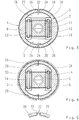
- FIG. 1 The perspective view after Fig. 1 reveals the essential parts of the illustrated embodiment of a bush bearing.
- This has an inner part identified by reference number 2.
- This is a metallic component with a hole.
- This inner part 2 is completely surrounded by a cage identified by reference numeral 4.
- the cage 4 is formed from two cage shells 6, which are shaped identically.
- the cage shells 6 each form a flat contact surface 10 in their base identified by reference numeral 8.
- Elastic material is vulcanized onto this contact surface 10, which essentially lies between the planes Forms contact surfaces 10 and the outer surfaces of the inner part 2 extending bearing body 12.
- an intermediate plate 14 is provided and vulcanized into the elastic material.
- a chamber 16 is formed on the outer circumferential surface of the cage 4 at opposite circumferential sections. In the axial direction, each chamber 16 is delimited by two circumferential sealing rings 18 at each of its axial ends. These sealing rings 18 form the seal on the outside of the chamber 16 and the bush bearing.
- the circumferential sealing rings 18 are in any case formed in the region of the chambers 16 on legs 20 in the form of ring segments, which are each formed on the bearing shells 6 and which abut one another in a sealing region 22 of the cage shells 6. In the in the Figures 1 and two exemplary embodiment shown, this sealing takes place via elastomeric material, which also forms the bearing body 12 and in any case covers the cage shells 6 on their peripheral surfaces.
- the cage shells 6 added to a unit.
- the material provided in the joint area 22 is, however, so elastic that the cage shells 6 can be moved in the radial direction relative to one another in order to change their distance. With this change in distance, the tension state of the bearing body 12 is changed and the bush bearing is calibrated accordingly.
- this calibration does not lead to any significant deformation of the cage 4, since the cage shells 6 essentially retain their original shape and only the elastic material in the joint area 22 is elastically deformed, in particular pushed out of the joint area 22.
- Mutually opposite abutting surfaces 22 in the abutting area 22 and formed by the ring segment-shaped legs 20 can accordingly be arranged with a varying distance from one another for the calibration of the bush bearing.
- FIGS. 3 and 4 show a cross-sectional view above an in Figure 1 Chamber cover of chamber 16, identified by reference numeral 26, which is formed from the elastomeric material forming the bearing body 12.
- the chamber cover 26 has a slot 28 in the joint area. This slot 28 is provided in the extension of the opposing abutment surfaces 24.
- These abutment surfaces 24 of the cage shells 6 formed from a hard component (metal or hard plastic) are not clad with elastomeric material.
- the coating of the cage shell 6 extends on the outer circumference, ie the sealing ring 18 up to the slot 28.
- FIG 4 The installation state for the in Figure 3 shown embodiment is in Figure 4 clarifies.
- the two cage shells 6 have been moved radially towards one another, so that the abutment surfaces 24 now abut one another directly.
- the slot 28 is accordingly pressed together, as a result of which there is a seal with respect to the chamber 16.
- the sealing ring 18 is designed to be closed on the circumference and lies sealingly against the inner circumferential surface of the outer tube 30. Accordingly, the chambers 16 in the area of the chamber cover 26 and on the outer circumference are sealed off from the outer tube 30.
- the Figure 5 shows a section of a further exemplary embodiment and only clarifies the seal in the joint area 22 for this exemplary embodiment.
- This embodiment enables a relatively large radial mobility of opposing cage shells 6. These are covered on the inside with elastomer material, which forms an outwardly bent U-shaped fold 32 between the opposing abutment surfaces 24 of the leg 20 in the form of a ring segment. The fold 32 is only connected to the inside of the ring segment-shaped legs 20. Between the legs 20 this is exposed and accordingly allows a relatively large mobility of the cage shells 6 in the radial direction without the seal being lost in the circumferential direction.
Landscapes
- Engineering & Computer Science (AREA)
- General Engineering & Computer Science (AREA)
- Mechanical Engineering (AREA)
- Manufacturing & Machinery (AREA)
- Support Of The Bearing (AREA)
- Rolling Contact Bearings (AREA)
Claims (7)
- Coussinet destiné à être reçu dans un manchon extérieur avec une partie intérieure (2) s'étendant dans la direction axiale, un corps de palier (12) en matériau élastique entourant la partie intérieure (2) avec au moins deux chambres (16) destinées à recevoir un moyen d'amortissement et avec une cage (4) qui entoure le corps de palier (12) de façon périphérique et qui est formée d'au moins deux parties de cage (6) dont l'espacement peut être modifié dans la direction axiale, une zone de butée (22) prévue entre les parties de cage (6) étant rendue étanche, caractérisé en ce que les parties de cage (6) comportent, à des extrémités axiales opposées et à la hauteur de deux chambres (16) se faisant face, des branches (20) en forme de segment de cercle qui coopèrent de façon étanche.
- Coussinet selon la revendication 1, caractérisé en ce que les parties de cage (6) sont raccordées l'une à l'autre de façon mobile l'une par rapport à l'autre par le biais du matériau constituant le corps de palier (12).
- Coussinet selon la revendication 1 ou 2, caractérisé en ce qu'au moins une des surfaces de butée (24) des parties de cage (6) prévues dans la zone de butée (22) est munie d'un joint d'étanchéité.
- Coussinet selon la revendication 1 ou 2, caractérisé en ce qu'une couverture de chambre (26) côté frontal recouvrant la chambre (16) assure l'étanchéité de la zone de butée (22).
- Coussinet selon la revendication 4, caractérisé en ce que la couverture de chambre (26) est constituée de façon fendue dans la zone de butée (22).
- Coussinet selon l'une des revendications précédentes, caractérisé par au moins une bague d'étanchéité (18) entourant la cage (4) de façon périphérique.
- Coussinet selon l'une des revendications précédentes, caractérisé en ce que les chambres (15) sont rendues étanches dans la zone de butée (22), c'est-à-dire aux extrémités libres des branches (20) en forme de segment de cercle.
Applications Claiming Priority (2)
| Application Number | Priority Date | Filing Date | Title |
|---|---|---|---|
| DE102012213440.9A DE102012213440A1 (de) | 2012-07-31 | 2012-07-31 | Buchsenlager |
| PCT/EP2013/063797 WO2014019783A1 (fr) | 2012-07-31 | 2013-07-01 | Palier à coussinets |
Publications (2)
| Publication Number | Publication Date |
|---|---|
| EP2906850A1 EP2906850A1 (fr) | 2015-08-19 |
| EP2906850B1 true EP2906850B1 (fr) | 2020-05-06 |
Family
ID=48746492
Family Applications (1)
| Application Number | Title | Priority Date | Filing Date |
|---|---|---|---|
| EP13734040.2A Active EP2906850B1 (fr) | 2012-07-31 | 2013-07-01 | Palier à coussinets |
Country Status (4)
| Country | Link |
|---|---|
| US (1) | US9599156B2 (fr) |
| EP (1) | EP2906850B1 (fr) |
| DE (1) | DE102012213440A1 (fr) |
| WO (1) | WO2014019783A1 (fr) |
Families Citing this family (2)
| Publication number | Priority date | Publication date | Assignee | Title |
|---|---|---|---|---|
| DE102013209990A1 (de) | 2013-05-29 | 2014-12-04 | Zf Friedrichshafen Ag | Hydraulisch dämpfendes Gummilager |
| DE102018006805B4 (de) * | 2018-08-28 | 2020-12-17 | Sumitomo Riko Company Limited | Hydroelastisches Lager |
Family Cites Families (19)
| Publication number | Priority date | Publication date | Assignee | Title |
|---|---|---|---|---|
| US2621923A (en) * | 1947-03-01 | 1952-12-16 | Goodrich Co B F | Rubber spring |
| DE1955308C3 (de) * | 1969-11-04 | 1978-05-24 | Raoul Dipl.-Ing. 8992 Hengnau Joern | Gummi-Metall-Gelenkbuchse |
| JP3125290B2 (ja) * | 1986-12-23 | 2001-01-15 | 日産自動車株式会社 | 内外筒型流体封入式パワーユニツトマウント |
| JPH0185547U (fr) * | 1987-11-27 | 1989-06-07 | ||
| FR2650356B1 (fr) | 1989-07-31 | 1994-05-27 | Hutchinson | Perfectionnements apportes aux man chons antivibratoires hydrauliques |
| US5040774A (en) * | 1990-04-09 | 1991-08-20 | The Pullman Company | Hydraulic damping bushing |
| JPH0771513A (ja) | 1993-09-03 | 1995-03-17 | Tokai Rubber Ind Ltd | 高粘性流体封入式筒型マウント |
| US5397112A (en) * | 1994-05-05 | 1995-03-14 | The Pullman Company | Fluid-filled elastomeric suspension bushing |
| JPH08177951A (ja) * | 1994-12-27 | 1996-07-12 | Bridgestone Corp | 防振装置 |
| DE10146154B4 (de) * | 2001-09-19 | 2007-04-26 | Trelleborg Automotive Technical Centre Gmbh | Hydraulisch dämpfende Buchse |
| NO20021215A (no) * | 2002-03-12 | 2003-07-28 | Kongsberg Automotive Asa | Kobling |
| US6698731B2 (en) * | 2002-04-24 | 2004-03-02 | The Pullman Company | High compliance multiple chamber piston for fluid damped elastomer devices |
| JP2006022907A (ja) * | 2004-07-08 | 2006-01-26 | Tokai Rubber Ind Ltd | 液封式防振ブッシュ |
| DE102005043234B4 (de) * | 2005-09-09 | 2017-05-11 | Boge Elastmetall Gmbh | Verfahren zur Herstellung eines elastomeren Buchsenlagers |
| DE102006031348A1 (de) * | 2006-07-06 | 2008-01-10 | Woco Avs Gmbh | Elastisches Einsatzlager |
| FR2904075A1 (fr) | 2006-07-19 | 2008-01-25 | Hutchinson Sa | Support antivibratoire hydraulique, manchon interne pour un tel support et procede de fabrication d'un tel support. |
| DE102006052251B4 (de) | 2006-11-03 | 2012-03-01 | Zf Friedrichshafen Ag | Hydrobuchse mit verbesserter Dauerlauffestigkeit |
| DE102007026470B4 (de) * | 2007-06-05 | 2012-04-05 | Zf Friedrichshafen Ag | Vorgespanntes Hydrolager |
| JP5026999B2 (ja) * | 2008-02-12 | 2012-09-19 | 東海ゴム工業株式会社 | 流体封入式筒形防振装置 |
-
2012
- 2012-07-31 DE DE102012213440.9A patent/DE102012213440A1/de not_active Withdrawn
-
2013
- 2013-07-01 WO PCT/EP2013/063797 patent/WO2014019783A1/fr not_active Ceased
- 2013-07-01 US US14/418,803 patent/US9599156B2/en not_active Expired - Fee Related
- 2013-07-01 EP EP13734040.2A patent/EP2906850B1/fr active Active
Non-Patent Citations (1)
| Title |
|---|
| None * |
Also Published As
| Publication number | Publication date |
|---|---|
| US9599156B2 (en) | 2017-03-21 |
| CN104822964A (zh) | 2015-08-05 |
| US20150226258A1 (en) | 2015-08-13 |
| DE102012213440A1 (de) | 2014-02-27 |
| EP2906850A1 (fr) | 2015-08-19 |
| WO2014019783A1 (fr) | 2014-02-06 |
Similar Documents
| Publication | Publication Date | Title |
|---|---|---|
| EP2906851B1 (fr) | Coussinet assurant un amortissement hydraulique | |
| EP2906852B1 (fr) | Coussinet assurant un amortissement hydraulique | |
| DE10131075B4 (de) | Aggregatelager in Buchsenform | |
| DE102005029614B4 (de) | Buchsenlager mit radialem und/oder axialem Anschlag und Verfahren zur Erzeugung eines Axialanschlags bei einem Buchsenlager | |
| DE102008008246B4 (de) | Buchsenlager mit verringertem Bauraumbedarf | |
| DE102007060968A1 (de) | Lageranordnung für eine Tragrolle | |
| EP1287273B1 (fr) | Palier a coussinet-douille a amortissement hydraulique | |
| DE3431460A1 (de) | Fluidgefuellte federnde buchsenkonstruktion | |
| EP3504461B1 (fr) | Bloc de suspension | |
| DE102013204995A1 (de) | Verfahren zum Herstellen eines Lagers und Lager | |
| DE19919863A1 (de) | Gummilager mit radialer Wegbegrenzung und Dämpfungsmittelkanal | |
| DE3800656A1 (de) | Hydraulisch daempfende huelsengummifeder | |
| EP2906850B1 (fr) | Palier à coussinets | |
| DE102004031559A1 (de) | Elastomeres Buchsenlager mit verbessertem Torsionsverhalten | |
| DE102013220627B3 (de) | Verfahren zum Befestigen eines Zuganschlags an einer Kolbenstange eines Schwingungsdämpfers | |
| EP1707842B1 (fr) | Manchon à amortissement hydraulique avec étanchéité axiale | |
| DE102012006284A1 (de) | Lager und Verfahren zu dessen Herstellung | |
| DE102022113154B4 (de) | Elastomerlager mit Schutzkappe | |
| DE19910308B4 (de) | Hydraulisch dämpfendes Gummilager mit Axialanschlägen sowie ein Verfahren zur Herstellung eines solchen hydraulisch dämpfenden Gummilagers mit integrierten Axialanschlägen | |
| DE102012202311B4 (de) | Elastomerlager | |
| DE102007034475B4 (de) | Lageranordnung mit Hydrobuchse | |
| DE102020134593A1 (de) | Hydraulische Buchse mit Abstützstellen und Verfahren zur Herstellung einer solchen Buchse | |
| DE10351229B4 (de) | Hydraulisch dämpfendes Lager | |
| DE10157144A1 (de) | Hydraulisch dämpfende Gummibuchse | |
| EP2604884B1 (fr) | Support hydraulique et son utilisation |
Legal Events
| Date | Code | Title | Description |
|---|---|---|---|
| PUAI | Public reference made under article 153(3) epc to a published international application that has entered the european phase |
Free format text: ORIGINAL CODE: 0009012 |
|
| 17P | Request for examination filed |
Effective date: 20150618 |
|
| AK | Designated contracting states |
Kind code of ref document: A1 Designated state(s): AL AT BE BG CH CY CZ DE DK EE ES FI FR GB GR HR HU IE IS IT LI LT LU LV MC MK MT NL NO PL PT RO RS SE SI SK SM TR |
|
| AX | Request for extension of the european patent |
Extension state: BA ME |
|
| DAX | Request for extension of the european patent (deleted) | ||
| RAP1 | Party data changed (applicant data changed or rights of an application transferred) |
Owner name: BOGE ELASTMETALL GMBH Owner name: AUDI AG |
|
| STAA | Information on the status of an ep patent application or granted ep patent |
Free format text: STATUS: EXAMINATION IS IN PROGRESS |
|
| 17Q | First examination report despatched |
Effective date: 20190104 |
|
| GRAP | Despatch of communication of intention to grant a patent |
Free format text: ORIGINAL CODE: EPIDOSNIGR1 |
|
| STAA | Information on the status of an ep patent application or granted ep patent |
Free format text: STATUS: GRANT OF PATENT IS INTENDED |
|
| INTG | Intention to grant announced |
Effective date: 20191205 |
|
| GRAS | Grant fee paid |
Free format text: ORIGINAL CODE: EPIDOSNIGR3 |
|
| GRAA | (expected) grant |
Free format text: ORIGINAL CODE: 0009210 |
|
| STAA | Information on the status of an ep patent application or granted ep patent |
Free format text: STATUS: THE PATENT HAS BEEN GRANTED |
|
| AK | Designated contracting states |
Kind code of ref document: B1 Designated state(s): AL AT BE BG CH CY CZ DE DK EE ES FI FR GB GR HR HU IE IS IT LI LT LU LV MC MK MT NL NO PL PT RO RS SE SI SK SM TR |
|
| REG | Reference to a national code |
Ref country code: GB Ref legal event code: FG4D Free format text: NOT ENGLISH |
|
| REG | Reference to a national code |
Ref country code: CH Ref legal event code: EP Ref country code: AT Ref legal event code: REF Ref document number: 1267245 Country of ref document: AT Kind code of ref document: T Effective date: 20200515 |
|
| REG | Reference to a national code |
Ref country code: DE Ref legal event code: R096 Ref document number: 502013014690 Country of ref document: DE |
|
| REG | Reference to a national code |
Ref country code: IE Ref legal event code: FG4D Free format text: LANGUAGE OF EP DOCUMENT: GERMAN |
|
| REG | Reference to a national code |
Ref country code: LT Ref legal event code: MG4D |
|
| REG | Reference to a national code |
Ref country code: NL Ref legal event code: MP Effective date: 20200506 |
|
| PG25 | Lapsed in a contracting state [announced via postgrant information from national office to epo] |
Ref country code: IS Free format text: LAPSE BECAUSE OF FAILURE TO SUBMIT A TRANSLATION OF THE DESCRIPTION OR TO PAY THE FEE WITHIN THE PRESCRIBED TIME-LIMIT Effective date: 20200906 Ref country code: FI Free format text: LAPSE BECAUSE OF FAILURE TO SUBMIT A TRANSLATION OF THE DESCRIPTION OR TO PAY THE FEE WITHIN THE PRESCRIBED TIME-LIMIT Effective date: 20200506 Ref country code: PT Free format text: LAPSE BECAUSE OF FAILURE TO SUBMIT A TRANSLATION OF THE DESCRIPTION OR TO PAY THE FEE WITHIN THE PRESCRIBED TIME-LIMIT Effective date: 20200907 Ref country code: LT Free format text: LAPSE BECAUSE OF FAILURE TO SUBMIT A TRANSLATION OF THE DESCRIPTION OR TO PAY THE FEE WITHIN THE PRESCRIBED TIME-LIMIT Effective date: 20200506 Ref country code: SE Free format text: LAPSE BECAUSE OF FAILURE TO SUBMIT A TRANSLATION OF THE DESCRIPTION OR TO PAY THE FEE WITHIN THE PRESCRIBED TIME-LIMIT Effective date: 20200506 Ref country code: NO Free format text: LAPSE BECAUSE OF FAILURE TO SUBMIT A TRANSLATION OF THE DESCRIPTION OR TO PAY THE FEE WITHIN THE PRESCRIBED TIME-LIMIT Effective date: 20200806 Ref country code: GR Free format text: LAPSE BECAUSE OF FAILURE TO SUBMIT A TRANSLATION OF THE DESCRIPTION OR TO PAY THE FEE WITHIN THE PRESCRIBED TIME-LIMIT Effective date: 20200807 |
|
| PG25 | Lapsed in a contracting state [announced via postgrant information from national office to epo] |
Ref country code: RS Free format text: LAPSE BECAUSE OF FAILURE TO SUBMIT A TRANSLATION OF THE DESCRIPTION OR TO PAY THE FEE WITHIN THE PRESCRIBED TIME-LIMIT Effective date: 20200506 Ref country code: BG Free format text: LAPSE BECAUSE OF FAILURE TO SUBMIT A TRANSLATION OF THE DESCRIPTION OR TO PAY THE FEE WITHIN THE PRESCRIBED TIME-LIMIT Effective date: 20200806 Ref country code: LV Free format text: LAPSE BECAUSE OF FAILURE TO SUBMIT A TRANSLATION OF THE DESCRIPTION OR TO PAY THE FEE WITHIN THE PRESCRIBED TIME-LIMIT Effective date: 20200506 Ref country code: HR Free format text: LAPSE BECAUSE OF FAILURE TO SUBMIT A TRANSLATION OF THE DESCRIPTION OR TO PAY THE FEE WITHIN THE PRESCRIBED TIME-LIMIT Effective date: 20200506 |
|
| PG25 | Lapsed in a contracting state [announced via postgrant information from national office to epo] |
Ref country code: AL Free format text: LAPSE BECAUSE OF FAILURE TO SUBMIT A TRANSLATION OF THE DESCRIPTION OR TO PAY THE FEE WITHIN THE PRESCRIBED TIME-LIMIT Effective date: 20200506 Ref country code: NL Free format text: LAPSE BECAUSE OF FAILURE TO SUBMIT A TRANSLATION OF THE DESCRIPTION OR TO PAY THE FEE WITHIN THE PRESCRIBED TIME-LIMIT Effective date: 20200506 |
|
| PG25 | Lapsed in a contracting state [announced via postgrant information from national office to epo] |
Ref country code: DK Free format text: LAPSE BECAUSE OF FAILURE TO SUBMIT A TRANSLATION OF THE DESCRIPTION OR TO PAY THE FEE WITHIN THE PRESCRIBED TIME-LIMIT Effective date: 20200506 Ref country code: IT Free format text: LAPSE BECAUSE OF FAILURE TO SUBMIT A TRANSLATION OF THE DESCRIPTION OR TO PAY THE FEE WITHIN THE PRESCRIBED TIME-LIMIT Effective date: 20200506 Ref country code: EE Free format text: LAPSE BECAUSE OF FAILURE TO SUBMIT A TRANSLATION OF THE DESCRIPTION OR TO PAY THE FEE WITHIN THE PRESCRIBED TIME-LIMIT Effective date: 20200506 Ref country code: SM Free format text: LAPSE BECAUSE OF FAILURE TO SUBMIT A TRANSLATION OF THE DESCRIPTION OR TO PAY THE FEE WITHIN THE PRESCRIBED TIME-LIMIT Effective date: 20200506 Ref country code: RO Free format text: LAPSE BECAUSE OF FAILURE TO SUBMIT A TRANSLATION OF THE DESCRIPTION OR TO PAY THE FEE WITHIN THE PRESCRIBED TIME-LIMIT Effective date: 20200506 Ref country code: CZ Free format text: LAPSE BECAUSE OF FAILURE TO SUBMIT A TRANSLATION OF THE DESCRIPTION OR TO PAY THE FEE WITHIN THE PRESCRIBED TIME-LIMIT Effective date: 20200506 Ref country code: ES Free format text: LAPSE BECAUSE OF FAILURE TO SUBMIT A TRANSLATION OF THE DESCRIPTION OR TO PAY THE FEE WITHIN THE PRESCRIBED TIME-LIMIT Effective date: 20200506 |
|
| REG | Reference to a national code |
Ref country code: DE Ref legal event code: R097 Ref document number: 502013014690 Country of ref document: DE |
|
| PG25 | Lapsed in a contracting state [announced via postgrant information from national office to epo] |
Ref country code: PL Free format text: LAPSE BECAUSE OF FAILURE TO SUBMIT A TRANSLATION OF THE DESCRIPTION OR TO PAY THE FEE WITHIN THE PRESCRIBED TIME-LIMIT Effective date: 20200506 Ref country code: SK Free format text: LAPSE BECAUSE OF FAILURE TO SUBMIT A TRANSLATION OF THE DESCRIPTION OR TO PAY THE FEE WITHIN THE PRESCRIBED TIME-LIMIT Effective date: 20200506 Ref country code: MC Free format text: LAPSE BECAUSE OF FAILURE TO SUBMIT A TRANSLATION OF THE DESCRIPTION OR TO PAY THE FEE WITHIN THE PRESCRIBED TIME-LIMIT Effective date: 20200506 |
|
| REG | Reference to a national code |
Ref country code: CH Ref legal event code: PL |
|
| PLBE | No opposition filed within time limit |
Free format text: ORIGINAL CODE: 0009261 |
|
| STAA | Information on the status of an ep patent application or granted ep patent |
Free format text: STATUS: NO OPPOSITION FILED WITHIN TIME LIMIT |
|
| 26N | No opposition filed |
Effective date: 20210209 |
|
| GBPC | Gb: european patent ceased through non-payment of renewal fee |
Effective date: 20200806 |
|
| REG | Reference to a national code |
Ref country code: BE Ref legal event code: MM Effective date: 20200731 |
|
| PG25 | Lapsed in a contracting state [announced via postgrant information from national office to epo] |
Ref country code: IE Free format text: LAPSE BECAUSE OF NON-PAYMENT OF DUE FEES Effective date: 20200701 Ref country code: LI Free format text: LAPSE BECAUSE OF NON-PAYMENT OF DUE FEES Effective date: 20200731 Ref country code: CH Free format text: LAPSE BECAUSE OF NON-PAYMENT OF DUE FEES Effective date: 20200731 Ref country code: FR Free format text: LAPSE BECAUSE OF NON-PAYMENT OF DUE FEES Effective date: 20200706 Ref country code: LU Free format text: LAPSE BECAUSE OF NON-PAYMENT OF DUE FEES Effective date: 20200701 |
|
| PG25 | Lapsed in a contracting state [announced via postgrant information from national office to epo] |
Ref country code: BE Free format text: LAPSE BECAUSE OF NON-PAYMENT OF DUE FEES Effective date: 20200731 Ref country code: SI Free format text: LAPSE BECAUSE OF FAILURE TO SUBMIT A TRANSLATION OF THE DESCRIPTION OR TO PAY THE FEE WITHIN THE PRESCRIBED TIME-LIMIT Effective date: 20200506 |
|
| PG25 | Lapsed in a contracting state [announced via postgrant information from national office to epo] |
Ref country code: GB Free format text: LAPSE BECAUSE OF NON-PAYMENT OF DUE FEES Effective date: 20200806 |
|
| REG | Reference to a national code |
Ref country code: AT Ref legal event code: MM01 Ref document number: 1267245 Country of ref document: AT Kind code of ref document: T Effective date: 20200701 |
|
| PG25 | Lapsed in a contracting state [announced via postgrant information from national office to epo] |
Ref country code: AT Free format text: LAPSE BECAUSE OF NON-PAYMENT OF DUE FEES Effective date: 20200701 |
|
| PG25 | Lapsed in a contracting state [announced via postgrant information from national office to epo] |
Ref country code: TR Free format text: LAPSE BECAUSE OF FAILURE TO SUBMIT A TRANSLATION OF THE DESCRIPTION OR TO PAY THE FEE WITHIN THE PRESCRIBED TIME-LIMIT Effective date: 20200506 Ref country code: MT Free format text: LAPSE BECAUSE OF FAILURE TO SUBMIT A TRANSLATION OF THE DESCRIPTION OR TO PAY THE FEE WITHIN THE PRESCRIBED TIME-LIMIT Effective date: 20200506 Ref country code: CY Free format text: LAPSE BECAUSE OF FAILURE TO SUBMIT A TRANSLATION OF THE DESCRIPTION OR TO PAY THE FEE WITHIN THE PRESCRIBED TIME-LIMIT Effective date: 20200506 |
|
| PG25 | Lapsed in a contracting state [announced via postgrant information from national office to epo] |
Ref country code: MK Free format text: LAPSE BECAUSE OF FAILURE TO SUBMIT A TRANSLATION OF THE DESCRIPTION OR TO PAY THE FEE WITHIN THE PRESCRIBED TIME-LIMIT Effective date: 20200506 |
|
| PGFP | Annual fee paid to national office [announced via postgrant information from national office to epo] |
Ref country code: DE Payment date: 20220713 Year of fee payment: 10 |
|
| P01 | Opt-out of the competence of the unified patent court (upc) registered |
Effective date: 20230530 |
|
| REG | Reference to a national code |
Ref country code: DE Ref legal event code: R119 Ref document number: 502013014690 Country of ref document: DE |
|
| PG25 | Lapsed in a contracting state [announced via postgrant information from national office to epo] |
Ref country code: DE Free format text: LAPSE BECAUSE OF NON-PAYMENT OF DUE FEES Effective date: 20240201 |