EP2906837B1 - Selbstfurchende schraube - Google Patents
Selbstfurchende schraube Download PDFInfo
- Publication number
- EP2906837B1 EP2906837B1 EP12821254.5A EP12821254A EP2906837B1 EP 2906837 B1 EP2906837 B1 EP 2906837B1 EP 12821254 A EP12821254 A EP 12821254A EP 2906837 B1 EP2906837 B1 EP 2906837B1
- Authority
- EP
- European Patent Office
- Prior art keywords
- thread
- sin
- section
- cross
- self
- Prior art date
- Legal status (The legal status is an assumption and is not a legal conclusion. Google has not performed a legal analysis and makes no representation as to the accuracy of the status listed.)
- Not-in-force
Links
- 238000010079 rubber tapping Methods 0.000 title claims description 21
- 239000000463 material Substances 0.000 claims description 6
- 230000001419 dependent effect Effects 0.000 claims description 3
- 238000005096 rolling process Methods 0.000 description 12
- 238000010276 construction Methods 0.000 description 10
- 239000004033 plastic Substances 0.000 description 7
- 229920003023 plastic Polymers 0.000 description 7
- 238000004364 calculation method Methods 0.000 description 5
- 229920001169 thermoplastic Polymers 0.000 description 5
- 229920001187 thermosetting polymer Polymers 0.000 description 5
- 239000004416 thermosoftening plastic Substances 0.000 description 5
- 229910052751 metal Inorganic materials 0.000 description 4
- 239000002184 metal Substances 0.000 description 4
- 150000002739 metals Chemical class 0.000 description 4
- 230000008859 change Effects 0.000 description 3
- 230000008571 general function Effects 0.000 description 3
- 230000007704 transition Effects 0.000 description 3
- 230000000694 effects Effects 0.000 description 2
- 230000006870 function Effects 0.000 description 2
- 229920000642 polymer Polymers 0.000 description 2
- 229910045601 alloy Inorganic materials 0.000 description 1
- 239000000956 alloy Substances 0.000 description 1
- 238000000354 decomposition reaction Methods 0.000 description 1
- 238000009795 derivation Methods 0.000 description 1
- 230000002349 favourable effect Effects 0.000 description 1
- 230000003993 interaction Effects 0.000 description 1
- 230000009467 reduction Effects 0.000 description 1
- 238000010008 shearing Methods 0.000 description 1
Images


Classifications
-
- F—MECHANICAL ENGINEERING; LIGHTING; HEATING; WEAPONS; BLASTING
- F16—ENGINEERING ELEMENTS AND UNITS; GENERAL MEASURES FOR PRODUCING AND MAINTAINING EFFECTIVE FUNCTIONING OF MACHINES OR INSTALLATIONS; THERMAL INSULATION IN GENERAL
- F16B—DEVICES FOR FASTENING OR SECURING CONSTRUCTIONAL ELEMENTS OR MACHINE PARTS TOGETHER, e.g. NAILS, BOLTS, CIRCLIPS, CLAMPS, CLIPS OR WEDGES; JOINTS OR JOINTING
- F16B35/00—Screw-bolts; Stay-bolts; Screw-threaded studs; Screws; Set screws
- F16B35/04—Screw-bolts; Stay-bolts; Screw-threaded studs; Screws; Set screws with specially-shaped head or shaft in order to fix the bolt on or in an object
- F16B35/041—Specially-shaped shafts
-
- F—MECHANICAL ENGINEERING; LIGHTING; HEATING; WEAPONS; BLASTING
- F16—ENGINEERING ELEMENTS AND UNITS; GENERAL MEASURES FOR PRODUCING AND MAINTAINING EFFECTIVE FUNCTIONING OF MACHINES OR INSTALLATIONS; THERMAL INSULATION IN GENERAL
- F16B—DEVICES FOR FASTENING OR SECURING CONSTRUCTIONAL ELEMENTS OR MACHINE PARTS TOGETHER, e.g. NAILS, BOLTS, CIRCLIPS, CLAMPS, CLIPS OR WEDGES; JOINTS OR JOINTING
- F16B25/00—Screws that cut thread in the body into which they are screwed, e.g. wood screws
- F16B25/001—Screws that cut thread in the body into which they are screwed, e.g. wood screws characterised by the material of the body into which the screw is screwed
- F16B25/0015—Screws that cut thread in the body into which they are screwed, e.g. wood screws characterised by the material of the body into which the screw is screwed the material being a soft organic material, e.g. wood or plastic
-
- F—MECHANICAL ENGINEERING; LIGHTING; HEATING; WEAPONS; BLASTING
- F16—ENGINEERING ELEMENTS AND UNITS; GENERAL MEASURES FOR PRODUCING AND MAINTAINING EFFECTIVE FUNCTIONING OF MACHINES OR INSTALLATIONS; THERMAL INSULATION IN GENERAL
- F16B—DEVICES FOR FASTENING OR SECURING CONSTRUCTIONAL ELEMENTS OR MACHINE PARTS TOGETHER, e.g. NAILS, BOLTS, CIRCLIPS, CLAMPS, CLIPS OR WEDGES; JOINTS OR JOINTING
- F16B25/00—Screws that cut thread in the body into which they are screwed, e.g. wood screws
- F16B25/0036—Screws that cut thread in the body into which they are screwed, e.g. wood screws characterised by geometric details of the screw
- F16B25/0042—Screws that cut thread in the body into which they are screwed, e.g. wood screws characterised by geometric details of the screw characterised by the geometry of the thread, the thread being a ridge wrapped around the shaft of the screw
- F16B25/0047—Screws that cut thread in the body into which they are screwed, e.g. wood screws characterised by geometric details of the screw characterised by the geometry of the thread, the thread being a ridge wrapped around the shaft of the screw the ridge being characterised by its cross-section in the plane of the shaft axis
-
- F—MECHANICAL ENGINEERING; LIGHTING; HEATING; WEAPONS; BLASTING
- F16—ENGINEERING ELEMENTS AND UNITS; GENERAL MEASURES FOR PRODUCING AND MAINTAINING EFFECTIVE FUNCTIONING OF MACHINES OR INSTALLATIONS; THERMAL INSULATION IN GENERAL
- F16B—DEVICES FOR FASTENING OR SECURING CONSTRUCTIONAL ELEMENTS OR MACHINE PARTS TOGETHER, e.g. NAILS, BOLTS, CIRCLIPS, CLAMPS, CLIPS OR WEDGES; JOINTS OR JOINTING
- F16B25/00—Screws that cut thread in the body into which they are screwed, e.g. wood screws
- F16B25/0036—Screws that cut thread in the body into which they are screwed, e.g. wood screws characterised by geometric details of the screw
- F16B25/0042—Screws that cut thread in the body into which they are screwed, e.g. wood screws characterised by geometric details of the screw characterised by the geometry of the thread, the thread being a ridge wrapped around the shaft of the screw
- F16B25/0052—Screws that cut thread in the body into which they are screwed, e.g. wood screws characterised by geometric details of the screw characterised by the geometry of the thread, the thread being a ridge wrapped around the shaft of the screw the ridge having indentations, notches or the like in order to improve the cutting behaviour
Definitions
- the present invention relates to a self-tapping screw with a head and an external thread carrier.
- this object is achieved by a self-tapping screw according to claim 1.
- FIG. 1 shows a self-tapping screw 10 according to the invention with a head 12 and an external thread carrier 14.
- the external thread carrier 14 here has a self-tapping thread 16, this consists of a thread 18, the detailed design in FIG. 2 is explained in more detail.
- the head 12 of the screw 10 is provided with an internal force attack 20, this is a hexalobular réellekraftangriff.
- an internal force attack 20 this is a hexalobular réellekraftangriff.
- screws according to the invention can be manufactured with any other internal or external force attacks.
- the design of the external thread 16 in detail is based on Fig. 2 better recognizable.
- the thread 18 is here rounded over a radius of the main body or core of the external thread carrier 14 and has an intersection angle of its two flanks 22, 24 of 30 °. This value has emerged as the optimal experience value for self-tapping screws.
- the thread 18 is not symmetrical. Rather, its two flanks 22, 24 each have different angles to the vertical on the axis of rotation of the external thread carrier 14.
- the screw head facing edge 22 at an angle of about 20 °, while the side remote from the screw head 12 flank 24 only has an angle of about 10 °.
- the thread profile height is determined by the strength characteristic values of the screw and the component so that there is sufficient protection against stripping.
- FIG. 3 shows in this regard the detail "Z" of FIG. 2 from which the shape of the thread profile can be seen in more detail.
- the friction of the loaded flank side 22 is twice as large as the friction of the unloaded flank side 24.
- the self-locking is determined by the friction factor of the loaded flank side 22. This prevents an automatic release by vibration.
- the thread root is formed with a slope-dependent radius R k . This runs tangentially from the flank geometry to the bottom of the thread. This results in no additional notch effects in the core cross section, which could cause a reduction of the screw cross section under tensile load.
- R k slope-dependent radius
- P is the pitch of a thread and d l is the inside diameter of the hole into which the self-tapping screw is to be placed.
- d k is the core diameter of the screw 10.
- d l is the inner diameter of the hole into which the screw is to be placed.
- h is the height of the thread profile, ie the difference between the radius of the core of the external thread and the external radius of the external thread.
- FIG. 4 shows a sectional view of a pentalobular core according to the invention an external thread 14 of a screw 10 according to the invention.
- this cross-section has the shape of a strongly rounded 5-corner.
- This shape is generated by always alternating regions 26 with a small radius k and regions 28 with a large radius R and tangentially merging the outer contour of the core cross-section at the transition points between the regions 26 with a small radius r and the regions 28 with a large radius R.
- FIG. 5 shows the corresponding geometric construction even more clearly.
- a circle with a radius ⁇ is drawn around the passage point M of the axis of rotation of the external thread through the cut surface.
- Five equidistant points 30 are determined on this circle, that is to say they each have a spacing of 72 degrees of angle as seen from the center M. From these points 30, small radii r are drawn on the side of the points 30 remote from the center M, and radii of a large radius R are drawn on the side beyond the midpoint M, viewed from the respective point 30.
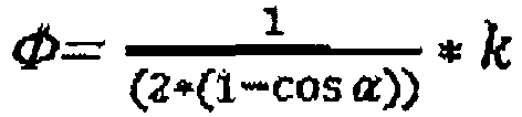
- the inner circle radius ⁇ is to be determined from the predefined values, as will be described below with reference to the drawing of FIG. 6 he follows.
- R r + ⁇ ⁇ sin 2 72 ° sin 54 ° ⁇ sin 36 ° ⁇
- R - r ⁇ ⁇ sin 2 72 ° sin 54 ° ⁇ sin 36 °
- a value for the pitch P of 2.24 mm a value for the core diameter d k of 2.65 mm, and a preferred out-of-roundness of the pentalobular cross-section k of 0.090 mm are obtained.
- the main values are determined in tabular form for determination of the pentalobular outer contour of the polygonal cross section k is given as follows: SP thread design (All dimensions in mm) d 3.0 4.0 5.0 P 1.34 1.79 2.24 d k 1.63 2.14 2.65 k 0.054 0.072 0,090 d 6.0 7.0 8.0 P 2.69 3,140 3.59 d k 3.16 3,670 4.18 k 0.108 0.126 0.144
- Core radius Rk 0 . 25
- P mm Out-of-roundness k 0 . 04 P mm
- the area A of the polygon roller cross section thus results in 11.34 mm 2 .
- thermosets For thermosets, the following calculation results for the preferred thread parameters:
- the area A of the polygonal rolling cross section is thus 12.65 mm 2 .
- the area A of the polygonal rolling cross-section is thus 13.05 mm 2 .
- This product with pentalobular cross-section has a thread form according to DIN 13. Due to the product transition from the form and furrow area as well as the pentalobular basic shape, these products are not teachings. All dimensions are in mm. thread M4 M5 M6 Threading ⁇ - D 4.0 5.0 6.0 Gradient - P 0.7 0.8 1.0 Kernnenn ⁇ - d k 3,141 4,019 4,773 Out of roundness - k 0.053 0,060 0,075 Hüllnik0 - C 4.05 5.06 6.08 Inner circle ⁇ - E 3.95 4.94 5.92
- FIG. 12 shows the geometric construction and the corresponding dimension for a heptalobularen cross section, ie a core cross section in the form of a rounded 7-corner.
Landscapes
- Engineering & Computer Science (AREA)
- General Engineering & Computer Science (AREA)
- Mechanical Engineering (AREA)
- Physics & Mathematics (AREA)
- Geometry (AREA)
- Chemical & Material Sciences (AREA)
- Life Sciences & Earth Sciences (AREA)
- Dispersion Chemistry (AREA)
- Wood Science & Technology (AREA)
- Connection Of Plates (AREA)
- Injection Moulding Of Plastics Or The Like (AREA)
- Extrusion Moulding Of Plastics Or The Like (AREA)
- Length Measuring Devices By Optical Means (AREA)
- Golf Clubs (AREA)
Description
- Die vorliegende Erfindung betrifft eine selbstfurchende Schraube mit einem Kopf und einem Außengewindeträger.
- Selbstfurchende Schrauben sind schon seit langem bekannt. Dabei tritt jedoch das Problem auf, dass insbesondere bei der Montage selbstfurchender Schrauben in Kunststoffe aufgrund der hohen Reibung zwischen dem Schraubenmaterial und dem Kunststoff erhebliche Einschraubkräfte erforderlich sind. Dadurch wird die Montage mühsam.
- Der hierzu nächstgelegene Stand der Technik ergibt sich aus der
EP 2 292 939 A2 . Diese zeigt bereits eine selbstfurchende Schraube mit einem Kopf und einem Außengewindeträger, bei der der Kernquerschnitt des Außengewindeträgers die Form eines abgerundeten N-Ecks aufweist. - Hiervon ausgehend ist es Aufgabe der vorliegenden Erfindung, eine solche selbstfurchende Schraube dahingehend weiterzuentwickeln, dass die Montage einfacher wird.
- Erfindungsgemäß wird diese Aufgabe durch eine selbstfurchende Schraube gemäß Anspruch 1 gelöst. Durch diese Konstruktion können die Bauteilspannungen (Druckeigenspannungen), die während des Einschraubvorganges entstehen, durch den Freiraum (Hinterschnitt), der durch die Polygonform gebildet wird, abgebaut werden. Weiter ergibt sich dadurch eine zusätzliche Montageerleichterung in Folge der besseren Selbstzentrierung während des Einschraubvorganges.
- Eine vorteilhafte Weiterbildung der vorliegenden Erfindung ergibt sich aus den Merkmalen des Unteranspruches.
- Die vorliegende Erfindung wird im Folgenden anhand des in den anliegenden Zeichnungen beschriebenen Ausführungsbeispieles näher erläutert. Es zeigt:
-
Fig. 1 eine erfindungsgemäße selbstfurchende Schraube von der Seite; -
Fig. 2 eine vergrößerte Darstellung eines Teiles des Außengewindeträgers der erfindungsgemäßen Schraube derFig. 1 ; -
Fig. 3 die Einzelheit "Z" derFig. 2 , -
Fig. 4 ein Beispiel für den pentalobularen Kernquerschnitt des Außengewindeträgers einer erfindungsgemäßen Schraube; -
Fig. 5 die geometrische Konstruktion, die zu dem Querschnitt derFig. 4 führt; -
Fig. 6 die geometrischen Hilfsüberlegungen, die zu der Konstruktion derFig. 5 führen; -
Fig. 7 weitere Erläuterungen zu der geometrischen Konstruktion der erfindungsgemäßen pentalobularen Kernquerschnitte des Außengewindeträgers; -
Fig. 8 einen anderen erfindungsgemäßen Kernquerschnitt für einen Außengewindeträger mit einem größeren k-Wert; -
Fig. 9 ein Kräfteparallelogramm an dem erfindungsgemäßen Gewindeprofil; -
Fig. 10 das Zusammenwirken der entsprechenden Kräfte derFig. 9 auf einander folgenden Gewindeprofilen; -
Fig. 11 die entsprechenden Kräfte im Werkstück, in das eine erfindungsgemäße Schraube geschraubt ist; und -
Fig. 12 einen erfindungsgemäßen Kernquerschnitt mit einer höheren Eckzahl, nämlich einen heptalobularen Querschnitt samt der hierfür erforderlichen geometrischen Konstruktionen. -
Figur 1 zeigt eine erfindungsgemäße selbstfurchende Schraube 10 mit einem Kopf 12 und einem Außengewindeträger 14. Der Außengewindeträger 14 weist hier ein selbstfurchendes Gewinde 16 auf, dieses besteht aus einem Gewindegang 18, dessen detaillierte Gestaltung inFigur 2 näher erläutert ist. - Der Kopf 12 der Schraube 10 ist mit einem Innenkraftangriff 20 versehen, hier handelt es sich um einen hexalobularen Innenkraftangriff. Selbstverständlich können erfindungsgemäße Schrauben mit beliebigen anderen Innen- oder Außenkraftangriffen gefertigt werden.
- Die Gestaltung des Außengewindes 16 im Einzelnen ist anhand der
Fig. 2 besser erkennbar. Der Gewindegang 18 geht hier über einen Radius abgerundet aus dem Grundkörper oder Kern des Außengewindeträgers 14 hervor und weist einen Schnittwinkel seiner beiden Flanken 22, 24 von 30° auf. Dieser Wert hat sich als für selbstfurchende Schrauben optimaler Erfahrungswert herauskristallisiert. - Erfindungsgemäß ist der Gewindegang 18 jedoch nicht symmetrisch. Vielmehr weisen seine beiden Flanken 22, 24 jeweils unterschiedliche Winkel zur Senkrechten auf der Rotationsachse des Außengewindeträgers 14 auf. Hierbei weist die dem Schraubenkopf zugewandte Flanke 22 einen Winkel von etwa 20° auf, während die vom Schraubenkopf 12 abgewandte Flanke 24 lediglich einen Winkel von etwa 10° aufweist.
- Das Gewindeprofil des Außengewindes 16 ist hier also asymmetrisch aufgebaut. Besonders bevorzugt ist es dabei, wenn der Flankenwinkel so aufgeteilt ist, dass sich der Tangenswert halbiert. Damit ergibt sich optimalerweise:


- Die Gewindeprofilhöhe wird über die Festigkeitskennwerte von Schraube und Bauteil bestimmt, damit eine ausreichende Sicherung gegen Abstreifen besteht.
- Durch diese Wahl der Flankenwinkel α1 und α2 verändern sich die Reibbeiwerte auf den Flankenhälften ebenfalls um diesen Betrag zwischen der unbelasteten und der belasteten Gewindeflanke. Bei genauer Berechnung ergeben sich die in
Figur 2 dargestellten Flankenwinkelseitenanteile von

- Diese Veränderung des Tangenswertes um 50 % bewirkt eine Änderung des Gewindereibbeiwertes auf den Flankenhälften, und damit eine Veränderung der Radial- und Hauptkräfte, wie in
Fig. 9 anhand von Kräfteparallelogrammen dargestellt. - Die Verschiebung der größeren Radialkraft zur belasteten Flankenseite hin bringt Vorteile für den Flankenreibbeiwert und die Selbsthemmung.
- Die Zerlegung der Axialkraft in der Schraube wirkt als Zuglast auf der belasteten Flankenseite und als Drucklast auf der unbelasteten Flankenseite durch das Bauteil. Drucklast des Bauteils und Zuglast der Schraube halten die Schraubverbindung im Gleichgewicht. Daraus ergeben sich folgende Radialkräfte:


- Diese resultierenden Hauptkräfte stehen senkrecht auf den Gewindeflanken. Die veränderten Hauptkräfte geben der Verbindung einen optimalen Halt gegen Abscherung des Innengewindes und ein günstiges Überdrehmoment der Schraube. Dies bewirkt die erfindungsgemäße Flankengeometrie, da die Hauptkräfte (F2 und F1) nicht vom Bauteil, sondern von der benachbarten Gewindeflanke aufgenommen werden, wie in
Fig. 10 dargestellt. -
Figur 3 zeigt diesbezüglich die Einzelheit "Z" derFigur 2 , aus der die Form des Gewindeprofils noch detaillierter erkennbar ist. - Da die Tangenswerte der Hälften auch die Reibungsfaktoren auf den Flankenseiten 22, 24 sind, ist die Reibung der belasteten Flankenseite 22 doppelt so groß wie die Reibung der unbelasteten Flankenseite 24. Die Selbsthemmung wird von dem Reibungsfaktor der belasteten Flankenseite 22 bestimmt. Dies verhindert ein selbsttätiges Lösen durch Vibration. Durch diese erfindungsgemäße Konstruktion bleiben die Vorspannkräfte in der Verbindung erhalten.
- Um den Materialfluss des zu furchenden Gewindes kontrolliert zu formen, ist der Gewindegrund mit einem steigungsabhängigen Radius Rk ausgebildet. Dieser läuft tangential von der Flankengeometrie zum Gewindegrund hin aus. Dadurch ergeben sich keine zusätzlichen Kerbwirkungen im Kernquerschnitt, die eine Minderung des Schraubenquerschnittes unter Zugbelastung bewirken könnten. Schließlich ergeben sich erfindungsgemäß unterschiedliche Optimumswerte für die Steigungen und Spannungsquerschnitte abhängig von dem Werkstoff, in den die erfindungsgemäße selbstfurchende Schraube 10 gesetzt werden soll.
- Für höherfeste Kunststoffe (z. B. Duroplaste) und Druckgusslegierungen werden kleinere Steigerungen und größere Spannungsquerschnitte gegenüber den Thermoplasten benötigt, damit die Schraubenverbindung den technischen Anforderungen optimal gewachsen ist. Steigungen und Kerndurchmesser sind Funktionen vom Außendurchmesser und den Festigkeitswerten von Bauteil und Schraube. Für die mathematische Geometrieauslegung gemäß
Fig. 11 werden folgende Festigkeitsgrundlagen benötigt: -

- Dabei ist P die Steigung eines Gewindeganges und dl der Innendurchmesser des Loches, in den die selbstfurchende Schraube gesetzt werden soll.
- Der Spannungsquerschnitt der Schraube ergibt sich zu

- Wobei dk der Kerndurchmesser der Schraube 10 ist.
- Das Widerstandsmoment des abstreifenden Kunststoffes ergibt sich zu.

- Wobei dl der Innendurchmesser des Loches ist, in das die Schraube gesetzt werden soll.
- Das Widerstandsmoment des Gewindezahngrundes ergibt sich dabei zu:

- Wobei h die Höhe des Gewindeprofils, also die Differenz zwischen dem Radius des Kerns des Außengewindes und dem Außenradius des Außengewindes ist.
- Für die Schraubenfestigkeit ergibt sich dann

- Und für das Drehmoment (Anzugsmoment) ergibt sich:

-
Figur 4 zeigt eine Schnittdarstellung eines erfindungsgemäßen pentalobularen Kerns eines Außengewindes 14 einer erfindungsgemäßen Schraube 10. Hierbei wird bereits erkennbar, dass dieser Querschnitt die Form eines stark abgerundeten 5-Ecks aufweist. - Diese Form wird dadurch erzeugt, dass sich Bereiche 26 mit kleinem Radius k und Bereiche 28 mit großem Radius R stets abwechseln und die Außenkontur des Kernquerschnittes an den Übergangsstellen zwischen den Bereichen 26 mit kleinem Radius r und den Bereichen 28 mit großem Radius R tangential ineinander übergehen.
- Die Konstruktion der Außenkontur des Querschnittes des Kerns des Außengewindes der erfindungsgemäßen selbstfurchenden Schraube wird im Folgenden anhand der
Figuren 5 bis 7 noch detaillierter erörtert, wobei gleiche Buchstaben gleiche Strecken in der geometrischen Darstellung bedeuten. -
Figur 5 zeigt die entsprechende geometrische Konstruktion noch wesentlich deutlicher. - Für die Konstruktion eines entsprechenden pentalobularen Querschnittes wird um den Durchtrittspunkt M der Rotationsachse des Außengewindes durch die Schnittfläche ein Kreis mit einem Radius φ gezogen. Auf diesem Kreis werden fünf äquidistante Punkte 30 bestimmt, diese weisen also vom Mittelpunkt M gesehen jeweils einen Abstand von 72 Winkelgrad auf. Von diesen Punkten 30 aus werden kleine Radien r auf der vom Mittelpunkt M abgelegenen Seite der Punkte 30 gezogen und Radien mit einem großen Radius R auf der von dem jeweiligen Punkt 30 aus gesehen jenseits des Mittelpunktes M gelegenen Seite.
- Es gelten dabei folgende Größenverhältnisse für die Radien R und r:
- Zur Berechnung dieser Radien müssen zuerst die anderen Größen in
Figur 5 bestimmt werden. Ausgegangen wird hierbei von dem durch die Norm vorgegebenen mittleren Kerndurchmesser D. Dieser bildet die Summe aus größem Radius R und kleinem Radius r. Es gilt also - Weiter existiert ein maximaler Außendurchmesser des rotierenden Querschnittes, der hier mit C bezeichnet wird.
- Die Differenz zwischen D und C ist der Wert k, dieser gibt die "Unrundheit" des jeweiligen pentalobulären Querschnittes an. Es gilt also

- Damit ergibt sich folgende weitere Herleitung für die erforderlichen Größen:


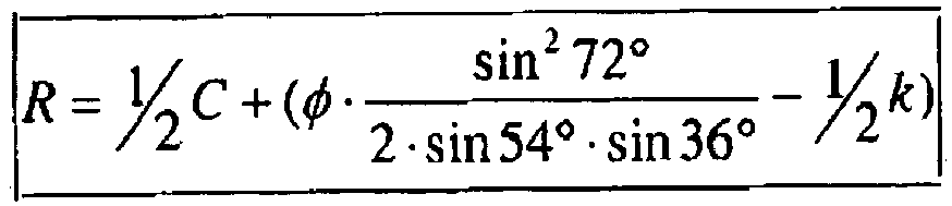


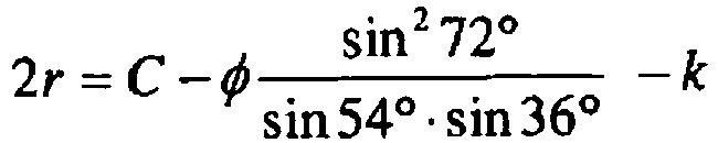


- Schließlich ist noch der Innenkreisradius φ aus den vorgegebenen Größen zu bestimmen, wie dies im Folgenden an Hand der Darstellung der beigefügten
Figur 6 erfolgt.


- Im Folgenden sollen zur Darstellung einer besonders bevorzugten Ausführungsform der Erfindung bevorzugte Gewindemaße für die verschiedenen Werkstoffklassen Polymerkunststoffe, Thermoplaste, Duroplaste und Leichtmetalle angegeben werden. Hierfür werden folgende allgemein gültige Funktionen vorausgesetzt:
-


- Gewindeabstand (Unterkopf) a = 2P max
- Gewindespitzenverrundung rs = 0,03P max

- Für die einzelnen Werkstoffe ergeben sich dabei also folgende Werte, jeweils ausgehend vom Nenndurchmesser d als Variable:
- Polymerkunststoffe
- SP-Gewindeform
- Beispielhaft ergibt sich hier für einen Nenndurchmesser von 5,0 ein Wert für die Steigung P mit 2,24 mm, ein Wert für den Kerndurchmesser dk von 2,65 mm und eine bevorzugte Unrundheit des pentalobularen Querschnittes k von 0,090 mm.
- Nunmehr ist noch der Walzdurchmesser dv für diese Werte bei einem Flankenwinkel α von 30° zu bestimmen, Dieser ergibt sich damit zu minimal 3,113 mm, als bevorzugter Wert ergibt sich somit aufgrund der Reserve von 0,05 mm für die Längung des Gewindes 3,163 mm. Das Polygonprofil ergibt sich für eine bevorzugte pentalobulare Form abgeleitet aus dem Walzdurchmesservorschlag von dv ≈ 3,16 mm = D für die oben beschriebenen Parameter der geometrischen Konstruktion des Außenumrisses des pentalobularen Querschnittes:
- C ≈ 3,25 mm
- D ≈ 3,16 mm
- E ≈ 3,07 mm
- R = 2,4519 mm
- r = 0,7108 mm
- φ= 0,9153mm und
- Im Folgenden werden tabellarisch die Hauptwerte (Nenndurchmesser d, Steigung P, Kerndurchmesser dk und Unrundheitswert k) zur Bestimmung des pentalobularen Außenumrisses des Polygon - Walzquerschnittes k wie folgt angegeben:
SP-Gewindeauslegung (Alle Maße in mm) d 3,0 4,0 5,0 P 1,34 1,79 2,24 dk 1,63 2,14 2,65 k 0,054 0,072 0,090 d 6,0 7,0 8,0 P 2,69 3,140 3,59 dk 3,16 3,670 4,18 k 0,108 0,126 0,144 - Für Thermoplaste ergibt sich folgende Berechnung für die bevorzugten Gewindekenngrößen:
-


- Beispielhaft ergibt sich hier wieder für einen Nenngewindedurchmesser von 5,0 mm die Steigung P zu 1,83 mm, der Kerndurchmesser dk zu 3,50 mm und die Unrundheit des pentalobularen Querschnittes zu k = 0,073 mm, für den Walzdurchmesser dv ergibt sich bei einem bevorzugten Flankenwinkel α von 30° 3,745 mm, mit einer Reserve von 0,05 mm für die Längung des Gewindes ergibt sich ein Walzdurchmesser von 3,80 mm. Die einzelnen Kenngrößen des pentalobularen Walzquerschnittes ergeben sich dann zu:
- C ≈ 3,87 mm
- k = 0,073 mm
- D ≈ 3,80 mm
- E ≈ 3,73 mm
- R = 2,6093 mm
- r = 1,1908 mm und
- φ = 0,7458 mm.
- Die Fläche A des Polygon - Walzquerschnittes ergibt sich damit zu 11,34 mm2.
- Die Hauptkenngrößen für andere Nenndurchmesser d für Spezialschrauben für Thermoplaste ergeben sich dann gemäß der folgenden Tabelle, wobei d wieder der Nenndurchmesser ist, P die Gewindesteigung, dk der Kerndurchmesser und k die Unrundheit des pentalobularen Querschnittes.
TP-Gewindeauslegung (Alle Maße in mm) d 2,5 3,0 3,5 4,0 4,5 P 0,98 1,15 1,32 1,49 1,66 dk 1,70 2,06 2,42 2,78 3,14 k 0,039 0,046 0,053 0,059 0,066 d 5,0 6,0 7,0 8,0 10,0 P 1,83 2,17 2,51 2,85 3,53 dk 3,50 4,22 4,94 5,66 7,10 k 0,073 0,087 0,100 0,114 0,141 - Für Duroplaste ergibt sich folgende Berechnung für die bevorzugten Gewindekenngrößen:
-
- Nennø d = Nennø (mm)
- Kernø dk = 0,75d-0,04 (mm)
- Steigung P = 0,19d+0,28 (mm)
- Zahnhöhe hz = 0,5(d-dk) (mm)
- Kernradius Rk = 0,2P (mm)
- Unrundheit k = 0,04P (mm)
- Beispielhaft ergibt sich hier wieder für einen Nenngewindedurchmesser von 5,0 mm die Steigung P zu 1,23 mm, der Kerndurchmesser dk zu 3,71 mm und die Unrundheit des pentalobularen Querschnittes zu k = 0,049 mm, für den Walzdurchmesser dv ergibt sich bei einem bevorzugten Flankenwinkel α von 30° 3,964 mm, mit einer Reserve von 0,05 mm für die Längung des Gewindes ergibt sich ein Walzdurchmesser von 4,01 mm. Die einzelnen Kenngrößen des pentalobularen Walzquerschnittes ergeben sich dann zu:
- C ≈ 4,06 mm
- k = 0,049 mm
- D ≈ 4,01 mm
- E ≈ 3,96 mm
- R = 2,4850 mm
- r = 1,5290 mm und
- φ = 0,5026 mm.
- Die Fläche A des Polygon - Walzquerschnittes ergibt sich damit zu 12,65 mm2.
- Die Hauptkenngrößen für andere Nenndurchmesser d für Spezialschrauben für Duroplaste ergeben sich dann gemäß der folgenden Tabelle, wobei d wieder der Nenndurchmesser ist, P die Gewindesteigung, dk der Kerndurchmesser und k die Unrundheit des pentalobularen Querschnittes.
DP-Gewindeauslegung (Alle Maße in mm) d 2,5 3,0 3,5 4,0 4,5 P 0,76 0,85 0,95 1,04 1,14 dk 1,84 2,21 2,59 2,96 3,34 k 0,030 0,034 0,038 0,042 0,045 d 5,0 6,0 7,0 8,0 10,0 P 1,230 1,42 1,61 1,800 2,18 dk 3,710 4,46 5,21 5,960 7,46 k 0,049 0,057 0,064 0,072 0.087 - Für Leichtmetalle ergibt sich folgende Berechnung für die bevorzugten Gewindekenngrößen:
-
- Nennø d = Nennø (mm)
- Kernø dk = 0,785d-0,11 (mm)
- Steigung P = 0,20d+0,30 (mm)
- Zahnhöhe hz = 0,5(d-dk) (mm)
- Kernradius Rk = 0,2P (mm)
- Unrundheit k = 0,04P (mm)
- Beispielhaft ergibt sich hier wieder für einen Nenngewindedurchmesser von 5,0 mm die Steigung P zu 1,30 mm, der Kerndurchmesser dk zu 3,82 mm und die Unrundheit des pentalobularen Querschnittes zu k = 0,052 mm, für den Walzdurchmesser dv ergibt sich bei einem bevorzugten Flankenwinkel α von 30° 4,027 mm, mit einer Reserve von 0,05 mm für die Längung des Gewindes ergibt sich ein Walzdurchmesser von 4,077 mm. Die einzelnen Kenngrößen des pentalobularen Walzquerschnittes ergeben sich dann zu:
- C ≈ 4,13mm
- k = 0,052 mm
- D ≈ 4,08 mm
- E ≈ 4,03 mm
- R = 2,5436 mm
- r = 1,5331 mm und
- φ = 0,5312 mm.
- Die Fläche A des Polygon - Walzquerschnittes ergibt sich damit zu 13,05 mm2.
- Die Hauptkenngrößen für andere Nenndurchmesser d für Spezialschrauben für Leichtmetalle ergeben sich dann gemäß der folgenden Tabelle, wobei d wieder der Nenndurchmesser ist, P die Gewindesteigung, dk der Kerndurchmesser und k die Unrundheit des pentalobularen Querschnittes.
LM-Gewindeauslegung (Alle Maße in mm) d 3,0 4,0 5,0 6,0 8,0 10,0 P 0,90 1,10 1,30 1,50 1,90 2,30 dk 2,25 3.02 3,82 4,60 6,17 7,74 k 0,036 0,044 0,052 0,060 0,078 0,092 - Weitere Produkte mit diesem pentalobularen Querschnitt sind Produkte mit Gewindeformen, die ihr eigenes Mutterngewinde formen und Durchzüge mit Mutterngewinde herstellen können. Dies sind namentlich :
- Pentalobulares, selbstfurchendes Befestigungselement für dünne Bleche
- Pentalobulares, selbstformendes Befestigungselement
- Diese Produkte haben eine Grundgewindeform nach DIN 13 und der GewindenennØ entspricht auch dem NennØ "D" der pentalobularen Grundform. Die Gewindeabmaße für Kern- und FlankenØ beziehen sich ebenfalls auf das D-Maß der pentalobularen Querschnittsform. Dies bedeutet auch, dass die ProduktØ "C" und "E" ebenfalls für Flanken- und KernØ gebildet werden müssen.
- Gewindetoleranzen nach DIN 13, gültig für den PolygonØ "D"
Unrundheit k = 0,075P - Für dieses Produkt mit pentalobularem Querschnitt wird die marktübliche Formspitze angesetzt. Die GewindenennØ sind entsprechend aus der DIN 13 zu entnehmen und mit dem entsprechenden Polygon0 "D" gleichzusetzen. Wegen der Produktgeometrie im Übergangsbereich ( Furchbereich) sowie der pentalobularen Grundform sind diese Produkte nicht lehrenhaltig.
- Dadurch ergeben sich für die pentalobularen selbstfurchenden Befestigungselemente für dünne Bleche folgende Geometriemaße:
Alle Maße sind in mm angegeben. Gewinde M4 M5 M6 Gewindenenn0 - D 4,0 5,0 6,0 Steigung - P 0,7 0,8 1,0 KernnennØ - dk 3,141 4,019 4,773 Unrundheit - k 0,053 0,060 0,075 HüllkreisØ - C 4,05 5,06 6,08 InnenkreisØ - E 3,95 4,94 5,92 - Weitere Gewindeabmessungen mit dieser Querschnittsform, sind ebenfalls herstellbar.
- Dieses Produkt mit pentalobularem Querschnitt hat eine Gewindeform nach DIN 13. Wegen des Produktübergangs von dem Form- und Furchbereich sowie der pentalobularen Grundform sind diese Produkte nicht lehrenhaltig.
Alle Maße sind in mm angegeben. Gewinde M4 M5 M6 GewindenennØ - D 4,0 5,0 6,0 Steigung - P 0,7 0,8 1,0 KernnennØ - dk 3,141 4,019 4,773 Unrundheit - k 0,053 0,060 0,075 Hüllkreis0 - C 4,05 5,06 6,08 InnenkreisØ - E 3,95 4,94 5,92 - Weitere Gewindeabmessungen mit dieser Querschnittsform, sind ebenfalls herstellbar.
- Als Beispiel für eine andere Ausführungsform der vorliegenden Erfindung mit einer höheren Eckzahl (n = 7) zeigt
Figur 12 die geometrische Konstruktion und die entsprechende Bemaßung für einen heptalobularen Querschnitt, d.h. einen Kernquerschnitt in Form eines abgerundeten 7-Ecks. - Allgemein gelten erfindungsgemäß die folgenden Formeln zur Berechnung beliebiger N-lobularer Querschnitte, wobei n die Anzahl der abgerundeten Polygonecken und k die Funktion der Gewindesteigung angibt:


Claims (2)
- Selbstfurchende Schraube (10) mit einem Kopf (12) und einem Außengewindeträger (14), bei der der Kernquerschnitt des Außengewindeträgers (14) die Form eines abgerundeten n-Ecks aufweist, wobei n eine Primzahl >3 ist, dadurch gekennzeichnet, dass die Form des abgerundeten n-Ecks aus 2n Bogenabschnitten (26, 28) mit abwechselnd einem großen Radius R und einem kleinen Radius r gebildet ist, wobei diese n-Mittelpunkte (30) der Radien R, r auf einem Hilfskreis, der koaxial innerhalb des Kernquerschnitts angeordnet ist, liegen, der einen Radius φ aufweist, und wobei jeder Mittelpunkt (30) dem nächstgelegenen Bogenabschnitt (26) mit kleinem Radius r und dem über dem Mittelpunkt (30) auf dem Hilfskreis gegenüberliegenden Bogenabschnitt (28) mit großem Radius R zugeordnet ist.
- Selbstfurchende Schraube (10) nach Anspruch 1, dadurch gekennzeichnet, dass die Abmaße des Kemquerschnittes des Außengewindeträgers (14) folgendermaßen bestimmt sind, wobei k die materialabhängig gewünschte Unrundheit des Gewindequerschnitts, C der Hüllkreisdurchmesser, D der Gewindenenndurchmesser ist:


Applications Claiming Priority (2)
| Application Number | Priority Date | Filing Date | Title |
|---|---|---|---|
| DE202012000045U DE202012000045U1 (de) | 2012-01-03 | 2012-01-03 | Selbstfurchende Schraube |
| PCT/DE2012/200085 WO2013102453A1 (de) | 2012-01-03 | 2012-12-19 | Selbstfurchende schraube |
Publications (2)
| Publication Number | Publication Date |
|---|---|
| EP2906837A1 EP2906837A1 (de) | 2015-08-19 |
| EP2906837B1 true EP2906837B1 (de) | 2016-09-14 |
Family
ID=45805174
Family Applications (1)
| Application Number | Title | Priority Date | Filing Date |
|---|---|---|---|
| EP12821254.5A Not-in-force EP2906837B1 (de) | 2012-01-03 | 2012-12-19 | Selbstfurchende schraube |
Country Status (6)
| Country | Link |
|---|---|
| US (1) | US9297403B2 (de) |
| EP (1) | EP2906837B1 (de) |
| CA (1) | CA2859688A1 (de) |
| DE (2) | DE202012000045U1 (de) |
| MX (1) | MX2014008193A (de) |
| WO (1) | WO2013102453A1 (de) |
Families Citing this family (7)
| Publication number | Priority date | Publication date | Assignee | Title |
|---|---|---|---|---|
| ITAN20130104A1 (it) | 2012-06-19 | 2013-12-20 | Norm Civata San Ve Tic A S | Forma della filettatura autoformante quadrata arrotondata per dispositivi di fissaggio e relativo metodo di produzione. |
| DE102013210476C5 (de) * | 2013-06-04 | 2021-04-29 | Baier & Michels Gmbh & Co. Kg | Verfahren zur Herstellung einer Schraube, insbesondere zur Verwendung in Kunststoffbauteilen |
| US20170254352A1 (en) * | 2014-11-13 | 2017-09-07 | Essence Method Refine Co., Ltd. | Fastener |
| US20160138640A1 (en) * | 2014-11-13 | 2016-05-19 | Essence Method Refine Co., Ltd. | Fastener |
| AU201614800S (en) * | 2016-08-31 | 2016-09-30 | Illinois Tool Works | A screw fastener |
| AU201614802S (en) * | 2016-08-31 | 2016-09-30 | Illinois Tool Works | A screw fastener |
| USD828149S1 (en) * | 2016-11-30 | 2018-09-11 | Hyundai Motor Company | Bolt |
Family Cites Families (8)
| Publication number | Priority date | Publication date | Assignee | Title |
|---|---|---|---|---|
| US2352982A (en) | 1942-06-25 | 1944-07-04 | American Screw Co | Screw for plastics |
| US3772720A (en) * | 1970-04-11 | 1973-11-20 | Res Engine Manuf Inc | Method for making a thread forming member |
| US3935785A (en) * | 1974-01-03 | 1976-02-03 | Rockford Headed Products, Inc. | Thread swaging screw |
| US3875780A (en) * | 1974-01-03 | 1975-04-08 | Rockford Headed Products | Method of making a thread forming screw |
| US5961267A (en) * | 1998-06-23 | 1999-10-05 | Textron Inc. | Thread forming fastener |
| US6375401B1 (en) * | 1999-10-20 | 2002-04-23 | Continental/Midland, Inc. | Fastener shank crossection utilizing non-circular constant breadth curves |
| US7677852B2 (en) * | 2004-08-30 | 2010-03-16 | Acument Intellectual Properties, Llc | Multi-lobular lockbolt |
| DE102009041877A1 (de) | 2009-09-07 | 2011-03-10 | Swg Schraubenwerk Gaisbach Gmbh | Betonschraube |
-
2012
- 2012-01-03 DE DE202012000045U patent/DE202012000045U1/de not_active Expired - Lifetime
- 2012-12-19 US US14/366,135 patent/US9297403B2/en not_active Expired - Fee Related
- 2012-12-19 EP EP12821254.5A patent/EP2906837B1/de not_active Not-in-force
- 2012-12-19 MX MX2014008193A patent/MX2014008193A/es not_active Application Discontinuation
- 2012-12-19 CA CA2859688A patent/CA2859688A1/en not_active Abandoned
- 2012-12-19 WO PCT/DE2012/200085 patent/WO2013102453A1/de not_active Ceased
- 2012-12-19 DE DE112012005558.6T patent/DE112012005558A5/de not_active Withdrawn
Also Published As
| Publication number | Publication date |
|---|---|
| CA2859688A1 (en) | 2013-07-11 |
| MX2014008193A (es) | 2014-10-14 |
| DE202012000045U1 (de) | 2012-02-08 |
| EP2906837A1 (de) | 2015-08-19 |
| WO2013102453A1 (de) | 2013-07-11 |
| US20140328646A1 (en) | 2014-11-06 |
| DE112012005558A5 (de) | 2014-12-18 |
| US9297403B2 (en) | 2016-03-29 |
Similar Documents
| Publication | Publication Date | Title |
|---|---|---|
| EP2906837B1 (de) | Selbstfurchende schraube | |
| DE69713568T2 (de) | Befestigungssystem mit schrauben | |
| EP3004666B1 (de) | Schraube | |
| DE4333791C2 (de) | Gewindeschneidschraube | |
| EP2047141B1 (de) | Kettennuss mit höherer tragkraft | |
| EP0660004A1 (de) | Befestigungselement mit spannungsoptimiertem Gewindeprofil | |
| EP2540410B1 (de) | Schraube und Verfahren zur Herstellung eines Schraubengewindes | |
| DE2257112A1 (de) | Selbstsichernde schrauben | |
| EP2638298B1 (de) | Gewindeerzeugende mutter, rohteil zur herstellung der mutter und schraubverbindung aus mutter und bolzen | |
| DE102011078686A1 (de) | Gewindeformende Schraube und Schraubverbindung sowie Rohling zur Herstellung der Schraube | |
| EP3649353A1 (de) | Befestigungsanordnung | |
| EP4325090A2 (de) | Gleitgewindetrieb mit asymmetrischem innen- und aussengewinde | |
| DE102015222889A1 (de) | Gewindeformende oder gewindefurchende Schraube, insbesondere zur Verwendung in Leichtmetall | |
| DE102014000940A1 (de) | Schraube, Befestigungsanordnung und Verwendung einer Schraube | |
| DE3300676A1 (de) | Befestigungselement mit gewinde und verfahren zu dessen herstellung | |
| DE102014109914A1 (de) | Zahnrad, Stirnradstufe sowie Verfahren zur Herstellung eines Zahnrads | |
| DE102015111456A1 (de) | Schraube für eine elektrische Kontaktverbindung | |
| DE2157373A1 (de) | Selbsthaltendes Befestigungselement und Werkzeug zu seiner Herstellung | |
| DE202018104400U1 (de) | Kombischraube | |
| WO2017102376A1 (de) | Gewindeelement | |
| EP3830432B1 (de) | Kombischraube | |
| DE102018008291A1 (de) | Befestigungselement mit mehrkantigem Außengewinde, Verfahren zu seiner Herstellung sowie Verbundelement und dessen Verwendung | |
| DE102016209597A1 (de) | Gewindeform mit verbesserter Kraftverteilung und verbessertem Löseschutz | |
| DE102024212243A1 (de) | Vorrichtung zum Verbinden von Bauteilen und Anordnung zum Ausgleich von Toleranzen | |
| DE102017103073A1 (de) | Werkzeug zum Gewindewalzen einer gewindeformenden Schraube, Verfahren zum Herstellen einer lochformenden und/oder gewindeformenden Schraube, sowie eine gewindeformende und/oder lochformende Schraube |
Legal Events
| Date | Code | Title | Description |
|---|---|---|---|
| PUAI | Public reference made under article 153(3) epc to a published international application that has entered the european phase |
Free format text: ORIGINAL CODE: 0009012 |
|
| 17P | Request for examination filed |
Effective date: 20140620 |
|
| AK | Designated contracting states |
Kind code of ref document: A1 Designated state(s): AL AT BE BG CH CY CZ DE DK EE ES FI FR GB GR HR HU IE IS IT LI LT LU LV MC MK MT NL NO PL PT RO RS SE SI SK SM TR |
|
| GRAP | Despatch of communication of intention to grant a patent |
Free format text: ORIGINAL CODE: EPIDOSNIGR1 |
|
| INTG | Intention to grant announced |
Effective date: 20160420 |
|
| GRAS | Grant fee paid |
Free format text: ORIGINAL CODE: EPIDOSNIGR3 |
|
| GRAA | (expected) grant |
Free format text: ORIGINAL CODE: 0009210 |
|
| AK | Designated contracting states |
Kind code of ref document: B1 Designated state(s): AL AT BE BG CH CY CZ DE DK EE ES FI FR GB GR HR HU IE IS IT LI LT LU LV MC MK MT NL NO PL PT RO RS SE SI SK SM TR |
|
| REG | Reference to a national code |
Ref country code: GB Ref legal event code: FG4D Free format text: NOT ENGLISH |
|
| REG | Reference to a national code |
Ref country code: CH Ref legal event code: EP |
|
| REG | Reference to a national code |
Ref country code: IE Ref legal event code: FG4D Free format text: LANGUAGE OF EP DOCUMENT: GERMAN |
|
| REG | Reference to a national code |
Ref country code: AT Ref legal event code: REF Ref document number: 829338 Country of ref document: AT Kind code of ref document: T Effective date: 20161015 |
|
| REG | Reference to a national code |
Ref country code: DE Ref legal event code: R096 Ref document number: 502012008289 Country of ref document: DE |
|
| REG | Reference to a national code |
Ref country code: LT Ref legal event code: MG4D |
|
| REG | Reference to a national code |
Ref country code: NL Ref legal event code: MP Effective date: 20160914 |
|
| REG | Reference to a national code |
Ref country code: FR Ref legal event code: PLFP Year of fee payment: 5 |
|
| PG25 | Lapsed in a contracting state [announced via postgrant information from national office to epo] |
Ref country code: RS Free format text: LAPSE BECAUSE OF FAILURE TO SUBMIT A TRANSLATION OF THE DESCRIPTION OR TO PAY THE FEE WITHIN THE PRESCRIBED TIME-LIMIT Effective date: 20160914 Ref country code: LT Free format text: LAPSE BECAUSE OF FAILURE TO SUBMIT A TRANSLATION OF THE DESCRIPTION OR TO PAY THE FEE WITHIN THE PRESCRIBED TIME-LIMIT Effective date: 20160914 Ref country code: NO Free format text: LAPSE BECAUSE OF FAILURE TO SUBMIT A TRANSLATION OF THE DESCRIPTION OR TO PAY THE FEE WITHIN THE PRESCRIBED TIME-LIMIT Effective date: 20161214 Ref country code: HR Free format text: LAPSE BECAUSE OF FAILURE TO SUBMIT A TRANSLATION OF THE DESCRIPTION OR TO PAY THE FEE WITHIN THE PRESCRIBED TIME-LIMIT Effective date: 20160914 Ref country code: FI Free format text: LAPSE BECAUSE OF FAILURE TO SUBMIT A TRANSLATION OF THE DESCRIPTION OR TO PAY THE FEE WITHIN THE PRESCRIBED TIME-LIMIT Effective date: 20160914 |
|
| PG25 | Lapsed in a contracting state [announced via postgrant information from national office to epo] |
Ref country code: NL Free format text: LAPSE BECAUSE OF FAILURE TO SUBMIT A TRANSLATION OF THE DESCRIPTION OR TO PAY THE FEE WITHIN THE PRESCRIBED TIME-LIMIT Effective date: 20160914 Ref country code: LV Free format text: LAPSE BECAUSE OF FAILURE TO SUBMIT A TRANSLATION OF THE DESCRIPTION OR TO PAY THE FEE WITHIN THE PRESCRIBED TIME-LIMIT Effective date: 20160914 Ref country code: GR Free format text: LAPSE BECAUSE OF FAILURE TO SUBMIT A TRANSLATION OF THE DESCRIPTION OR TO PAY THE FEE WITHIN THE PRESCRIBED TIME-LIMIT Effective date: 20161215 Ref country code: SE Free format text: LAPSE BECAUSE OF FAILURE TO SUBMIT A TRANSLATION OF THE DESCRIPTION OR TO PAY THE FEE WITHIN THE PRESCRIBED TIME-LIMIT Effective date: 20160914 |
|
| PG25 | Lapsed in a contracting state [announced via postgrant information from national office to epo] |
Ref country code: EE Free format text: LAPSE BECAUSE OF FAILURE TO SUBMIT A TRANSLATION OF THE DESCRIPTION OR TO PAY THE FEE WITHIN THE PRESCRIBED TIME-LIMIT Effective date: 20160914 Ref country code: RO Free format text: LAPSE BECAUSE OF FAILURE TO SUBMIT A TRANSLATION OF THE DESCRIPTION OR TO PAY THE FEE WITHIN THE PRESCRIBED TIME-LIMIT Effective date: 20160914 |
|
| PGFP | Annual fee paid to national office [announced via postgrant information from national office to epo] |
Ref country code: DE Payment date: 20170207 Year of fee payment: 5 Ref country code: CH Payment date: 20170125 Year of fee payment: 5 Ref country code: FR Payment date: 20170124 Year of fee payment: 5 Ref country code: MC Payment date: 20170123 Year of fee payment: 5 |
|
| PG25 | Lapsed in a contracting state [announced via postgrant information from national office to epo] |
Ref country code: PL Free format text: LAPSE BECAUSE OF FAILURE TO SUBMIT A TRANSLATION OF THE DESCRIPTION OR TO PAY THE FEE WITHIN THE PRESCRIBED TIME-LIMIT Effective date: 20160914 Ref country code: SM Free format text: LAPSE BECAUSE OF FAILURE TO SUBMIT A TRANSLATION OF THE DESCRIPTION OR TO PAY THE FEE WITHIN THE PRESCRIBED TIME-LIMIT Effective date: 20160914 Ref country code: PT Free format text: LAPSE BECAUSE OF FAILURE TO SUBMIT A TRANSLATION OF THE DESCRIPTION OR TO PAY THE FEE WITHIN THE PRESCRIBED TIME-LIMIT Effective date: 20170116 Ref country code: SK Free format text: LAPSE BECAUSE OF FAILURE TO SUBMIT A TRANSLATION OF THE DESCRIPTION OR TO PAY THE FEE WITHIN THE PRESCRIBED TIME-LIMIT Effective date: 20160914 Ref country code: CZ Free format text: LAPSE BECAUSE OF FAILURE TO SUBMIT A TRANSLATION OF THE DESCRIPTION OR TO PAY THE FEE WITHIN THE PRESCRIBED TIME-LIMIT Effective date: 20160914 Ref country code: ES Free format text: LAPSE BECAUSE OF FAILURE TO SUBMIT A TRANSLATION OF THE DESCRIPTION OR TO PAY THE FEE WITHIN THE PRESCRIBED TIME-LIMIT Effective date: 20160914 Ref country code: IS Free format text: LAPSE BECAUSE OF FAILURE TO SUBMIT A TRANSLATION OF THE DESCRIPTION OR TO PAY THE FEE WITHIN THE PRESCRIBED TIME-LIMIT Effective date: 20170114 Ref country code: BG Free format text: LAPSE BECAUSE OF FAILURE TO SUBMIT A TRANSLATION OF THE DESCRIPTION OR TO PAY THE FEE WITHIN THE PRESCRIBED TIME-LIMIT Effective date: 20161214 |
|
| PGFP | Annual fee paid to national office [announced via postgrant information from national office to epo] |
Ref country code: IE Payment date: 20170123 Year of fee payment: 5 Ref country code: GB Payment date: 20170125 Year of fee payment: 5 Ref country code: LU Payment date: 20170124 Year of fee payment: 5 Ref country code: BE Payment date: 20170124 Year of fee payment: 5 |
|
| REG | Reference to a national code |
Ref country code: DE Ref legal event code: R097 Ref document number: 502012008289 Country of ref document: DE |
|
| PG25 | Lapsed in a contracting state [announced via postgrant information from national office to epo] |
Ref country code: IT Free format text: LAPSE BECAUSE OF FAILURE TO SUBMIT A TRANSLATION OF THE DESCRIPTION OR TO PAY THE FEE WITHIN THE PRESCRIBED TIME-LIMIT Effective date: 20160914 |
|
| PLBE | No opposition filed within time limit |
Free format text: ORIGINAL CODE: 0009261 |
|
| STAA | Information on the status of an ep patent application or granted ep patent |
Free format text: STATUS: NO OPPOSITION FILED WITHIN TIME LIMIT |
|
| PG25 | Lapsed in a contracting state [announced via postgrant information from national office to epo] |
Ref country code: DK Free format text: LAPSE BECAUSE OF FAILURE TO SUBMIT A TRANSLATION OF THE DESCRIPTION OR TO PAY THE FEE WITHIN THE PRESCRIBED TIME-LIMIT Effective date: 20160914 |
|
| 26N | No opposition filed |
Effective date: 20170615 |
|
| PG25 | Lapsed in a contracting state [announced via postgrant information from national office to epo] |
Ref country code: SI Free format text: LAPSE BECAUSE OF FAILURE TO SUBMIT A TRANSLATION OF THE DESCRIPTION OR TO PAY THE FEE WITHIN THE PRESCRIBED TIME-LIMIT Effective date: 20160914 |
|
| PG25 | Lapsed in a contracting state [announced via postgrant information from national office to epo] |
Ref country code: HU Free format text: LAPSE BECAUSE OF FAILURE TO SUBMIT A TRANSLATION OF THE DESCRIPTION OR TO PAY THE FEE WITHIN THE PRESCRIBED TIME-LIMIT; INVALID AB INITIO Effective date: 20121219 |
|
| PG25 | Lapsed in a contracting state [announced via postgrant information from national office to epo] |
Ref country code: CY Free format text: LAPSE BECAUSE OF FAILURE TO SUBMIT A TRANSLATION OF THE DESCRIPTION OR TO PAY THE FEE WITHIN THE PRESCRIBED TIME-LIMIT Effective date: 20160914 Ref country code: MK Free format text: LAPSE BECAUSE OF FAILURE TO SUBMIT A TRANSLATION OF THE DESCRIPTION OR TO PAY THE FEE WITHIN THE PRESCRIBED TIME-LIMIT Effective date: 20160914 |
|
| REG | Reference to a national code |
Ref country code: DE Ref legal event code: R119 Ref document number: 502012008289 Country of ref document: DE |
|
| REG | Reference to a national code |
Ref country code: CH Ref legal event code: PL |
|
| GBPC | Gb: european patent ceased through non-payment of renewal fee |
Effective date: 20171219 |
|
| REG | Reference to a national code |
Ref country code: IE Ref legal event code: MM4A |
|
| PG25 | Lapsed in a contracting state [announced via postgrant information from national office to epo] |
Ref country code: LU Free format text: LAPSE BECAUSE OF NON-PAYMENT OF DUE FEES Effective date: 20171219 Ref country code: MT Free format text: LAPSE BECAUSE OF FAILURE TO SUBMIT A TRANSLATION OF THE DESCRIPTION OR TO PAY THE FEE WITHIN THE PRESCRIBED TIME-LIMIT Effective date: 20160914 |
|
| REG | Reference to a national code |
Ref country code: FR Ref legal event code: ST Effective date: 20180831 |
|
| REG | Reference to a national code |
Ref country code: BE Ref legal event code: MM Effective date: 20171231 |
|
| PG25 | Lapsed in a contracting state [announced via postgrant information from national office to epo] |
Ref country code: IE Free format text: LAPSE BECAUSE OF NON-PAYMENT OF DUE FEES Effective date: 20171219 Ref country code: FR Free format text: LAPSE BECAUSE OF NON-PAYMENT OF DUE FEES Effective date: 20180102 Ref country code: DE Free format text: LAPSE BECAUSE OF NON-PAYMENT OF DUE FEES Effective date: 20180703 Ref country code: AL Free format text: LAPSE BECAUSE OF FAILURE TO SUBMIT A TRANSLATION OF THE DESCRIPTION OR TO PAY THE FEE WITHIN THE PRESCRIBED TIME-LIMIT Effective date: 20160914 Ref country code: TR Free format text: LAPSE BECAUSE OF FAILURE TO SUBMIT A TRANSLATION OF THE DESCRIPTION OR TO PAY THE FEE WITHIN THE PRESCRIBED TIME-LIMIT Effective date: 20160914 |
|
| PG25 | Lapsed in a contracting state [announced via postgrant information from national office to epo] |
Ref country code: LI Free format text: LAPSE BECAUSE OF NON-PAYMENT OF DUE FEES Effective date: 20171231 Ref country code: CH Free format text: LAPSE BECAUSE OF NON-PAYMENT OF DUE FEES Effective date: 20171231 Ref country code: GB Free format text: LAPSE BECAUSE OF NON-PAYMENT OF DUE FEES Effective date: 20171219 Ref country code: BE Free format text: LAPSE BECAUSE OF NON-PAYMENT OF DUE FEES Effective date: 20171231 |
|
| REG | Reference to a national code |
Ref country code: AT Ref legal event code: MM01 Ref document number: 829338 Country of ref document: AT Kind code of ref document: T Effective date: 20171219 |
|
| PG25 | Lapsed in a contracting state [announced via postgrant information from national office to epo] |
Ref country code: AT Free format text: LAPSE BECAUSE OF NON-PAYMENT OF DUE FEES Effective date: 20171219 |
|
| PG25 | Lapsed in a contracting state [announced via postgrant information from national office to epo] |
Ref country code: MC Free format text: LAPSE BECAUSE OF NON-PAYMENT OF DUE FEES Effective date: 20180102 |