EP2906799B1 - Fuel system protection in a multi-fuel internal combustion engine - Google Patents
Fuel system protection in a multi-fuel internal combustion engine Download PDFInfo
- Publication number
- EP2906799B1 EP2906799B1 EP13845933.4A EP13845933A EP2906799B1 EP 2906799 B1 EP2906799 B1 EP 2906799B1 EP 13845933 A EP13845933 A EP 13845933A EP 2906799 B1 EP2906799 B1 EP 2906799B1
- Authority
- EP
- European Patent Office
- Prior art keywords
- fuel
- engine
- directly injected
- cylinder
- cylinders
- Prior art date
- Legal status (The legal status is an assumption and is not a legal conclusion. Google has not performed a legal analysis and makes no representation as to the accuracy of the status listed.)
- Active
Links
Images



Classifications
-
- F—MECHANICAL ENGINEERING; LIGHTING; HEATING; WEAPONS; BLASTING
- F02—COMBUSTION ENGINES; HOT-GAS OR COMBUSTION-PRODUCT ENGINE PLANTS
- F02D—CONTROLLING COMBUSTION ENGINES
- F02D41/00—Electrical control of supply of combustible mixture or its constituents
- F02D41/30—Controlling fuel injection
- F02D41/3094—Controlling fuel injection the fuel injection being effected by at least two different injectors, e.g. one in the intake manifold and one in the cylinder
-
- F—MECHANICAL ENGINEERING; LIGHTING; HEATING; WEAPONS; BLASTING
- F02—COMBUSTION ENGINES; HOT-GAS OR COMBUSTION-PRODUCT ENGINE PLANTS
- F02D—CONTROLLING COMBUSTION ENGINES
- F02D19/00—Controlling engines characterised by their use of non-liquid fuels, pluralities of fuels, or non-fuel substances added to the combustible mixtures
- F02D19/06—Controlling engines characterised by their use of non-liquid fuels, pluralities of fuels, or non-fuel substances added to the combustible mixtures peculiar to engines working with pluralities of fuels, e.g. alternatively with light and heavy fuel oil, other than engines indifferent to the fuel consumed
- F02D19/0602—Control of components of the fuel supply system
- F02D19/0607—Control of components of the fuel supply system to adjust the fuel mass or volume flow
- F02D19/061—Control of components of the fuel supply system to adjust the fuel mass or volume flow by controlling fuel injectors
-
- F—MECHANICAL ENGINEERING; LIGHTING; HEATING; WEAPONS; BLASTING
- F02—COMBUSTION ENGINES; HOT-GAS OR COMBUSTION-PRODUCT ENGINE PLANTS
- F02D—CONTROLLING COMBUSTION ENGINES
- F02D19/00—Controlling engines characterised by their use of non-liquid fuels, pluralities of fuels, or non-fuel substances added to the combustible mixtures
- F02D19/06—Controlling engines characterised by their use of non-liquid fuels, pluralities of fuels, or non-fuel substances added to the combustible mixtures peculiar to engines working with pluralities of fuels, e.g. alternatively with light and heavy fuel oil, other than engines indifferent to the fuel consumed
- F02D19/0623—Failure diagnosis or prevention; Safety measures; Testing
-
- F—MECHANICAL ENGINEERING; LIGHTING; HEATING; WEAPONS; BLASTING
- F02—COMBUSTION ENGINES; HOT-GAS OR COMBUSTION-PRODUCT ENGINE PLANTS
- F02D—CONTROLLING COMBUSTION ENGINES
- F02D19/00—Controlling engines characterised by their use of non-liquid fuels, pluralities of fuels, or non-fuel substances added to the combustible mixtures
- F02D19/06—Controlling engines characterised by their use of non-liquid fuels, pluralities of fuels, or non-fuel substances added to the combustible mixtures peculiar to engines working with pluralities of fuels, e.g. alternatively with light and heavy fuel oil, other than engines indifferent to the fuel consumed
- F02D19/0639—Controlling engines characterised by their use of non-liquid fuels, pluralities of fuels, or non-fuel substances added to the combustible mixtures peculiar to engines working with pluralities of fuels, e.g. alternatively with light and heavy fuel oil, other than engines indifferent to the fuel consumed characterised by the type of fuels
- F02D19/0642—Controlling engines characterised by their use of non-liquid fuels, pluralities of fuels, or non-fuel substances added to the combustible mixtures peculiar to engines working with pluralities of fuels, e.g. alternatively with light and heavy fuel oil, other than engines indifferent to the fuel consumed characterised by the type of fuels at least one fuel being gaseous, the other fuels being gaseous or liquid at standard conditions
- F02D19/0647—Controlling engines characterised by their use of non-liquid fuels, pluralities of fuels, or non-fuel substances added to the combustible mixtures peculiar to engines working with pluralities of fuels, e.g. alternatively with light and heavy fuel oil, other than engines indifferent to the fuel consumed characterised by the type of fuels at least one fuel being gaseous, the other fuels being gaseous or liquid at standard conditions the gaseous fuel being liquefied petroleum gas [LPG], liquefied natural gas [LNG], compressed natural gas [CNG] or dimethyl ether [DME]
-
- F—MECHANICAL ENGINEERING; LIGHTING; HEATING; WEAPONS; BLASTING
- F02—COMBUSTION ENGINES; HOT-GAS OR COMBUSTION-PRODUCT ENGINE PLANTS
- F02D—CONTROLLING COMBUSTION ENGINES
- F02D19/00—Controlling engines characterised by their use of non-liquid fuels, pluralities of fuels, or non-fuel substances added to the combustible mixtures
- F02D19/06—Controlling engines characterised by their use of non-liquid fuels, pluralities of fuels, or non-fuel substances added to the combustible mixtures peculiar to engines working with pluralities of fuels, e.g. alternatively with light and heavy fuel oil, other than engines indifferent to the fuel consumed
- F02D19/0663—Details on the fuel supply system, e.g. tanks, valves, pipes, pumps, rails, injectors or mixers
- F02D19/0686—Injectors
- F02D19/0689—Injectors for in-cylinder direct injection
-
- F—MECHANICAL ENGINEERING; LIGHTING; HEATING; WEAPONS; BLASTING
- F02—COMBUSTION ENGINES; HOT-GAS OR COMBUSTION-PRODUCT ENGINE PLANTS
- F02D—CONTROLLING COMBUSTION ENGINES
- F02D19/00—Controlling engines characterised by their use of non-liquid fuels, pluralities of fuels, or non-fuel substances added to the combustible mixtures
- F02D19/06—Controlling engines characterised by their use of non-liquid fuels, pluralities of fuels, or non-fuel substances added to the combustible mixtures peculiar to engines working with pluralities of fuels, e.g. alternatively with light and heavy fuel oil, other than engines indifferent to the fuel consumed
- F02D19/0663—Details on the fuel supply system, e.g. tanks, valves, pipes, pumps, rails, injectors or mixers
- F02D19/0686—Injectors
- F02D19/0692—Arrangement of multiple injectors per combustion chamber
-
- F—MECHANICAL ENGINEERING; LIGHTING; HEATING; WEAPONS; BLASTING
- F02—COMBUSTION ENGINES; HOT-GAS OR COMBUSTION-PRODUCT ENGINE PLANTS
- F02D—CONTROLLING COMBUSTION ENGINES
- F02D19/00—Controlling engines characterised by their use of non-liquid fuels, pluralities of fuels, or non-fuel substances added to the combustible mixtures
- F02D19/06—Controlling engines characterised by their use of non-liquid fuels, pluralities of fuels, or non-fuel substances added to the combustible mixtures peculiar to engines working with pluralities of fuels, e.g. alternatively with light and heavy fuel oil, other than engines indifferent to the fuel consumed
- F02D19/08—Controlling engines characterised by their use of non-liquid fuels, pluralities of fuels, or non-fuel substances added to the combustible mixtures peculiar to engines working with pluralities of fuels, e.g. alternatively with light and heavy fuel oil, other than engines indifferent to the fuel consumed simultaneously using pluralities of fuels
- F02D19/081—Adjusting the fuel composition or mixing ratio; Transitioning from one fuel to the other
-
- F—MECHANICAL ENGINEERING; LIGHTING; HEATING; WEAPONS; BLASTING
- F02—COMBUSTION ENGINES; HOT-GAS OR COMBUSTION-PRODUCT ENGINE PLANTS
- F02D—CONTROLLING COMBUSTION ENGINES
- F02D41/00—Electrical control of supply of combustible mixture or its constituents
- F02D41/0025—Controlling engines characterised by use of non-liquid fuels, pluralities of fuels, or non-fuel substances added to the combustible mixtures
-
- F—MECHANICAL ENGINEERING; LIGHTING; HEATING; WEAPONS; BLASTING
- F02—COMBUSTION ENGINES; HOT-GAS OR COMBUSTION-PRODUCT ENGINE PLANTS
- F02D—CONTROLLING COMBUSTION ENGINES
- F02D41/00—Electrical control of supply of combustible mixture or its constituents
- F02D41/0025—Controlling engines characterised by use of non-liquid fuels, pluralities of fuels, or non-fuel substances added to the combustible mixtures
- F02D41/0027—Controlling engines characterised by use of non-liquid fuels, pluralities of fuels, or non-fuel substances added to the combustible mixtures the fuel being gaseous
-
- F—MECHANICAL ENGINEERING; LIGHTING; HEATING; WEAPONS; BLASTING
- F02—COMBUSTION ENGINES; HOT-GAS OR COMBUSTION-PRODUCT ENGINE PLANTS
- F02D—CONTROLLING COMBUSTION ENGINES
- F02D41/00—Electrical control of supply of combustible mixture or its constituents
- F02D41/008—Controlling each cylinder individually
- F02D41/0087—Selective cylinder activation, i.e. partial cylinder operation
-
- F—MECHANICAL ENGINEERING; LIGHTING; HEATING; WEAPONS; BLASTING
- F02—COMBUSTION ENGINES; HOT-GAS OR COMBUSTION-PRODUCT ENGINE PLANTS
- F02D—CONTROLLING COMBUSTION ENGINES
- F02D41/00—Electrical control of supply of combustible mixture or its constituents
- F02D41/30—Controlling fuel injection
- F02D41/38—Controlling fuel injection of the high pressure type
-
- F—MECHANICAL ENGINEERING; LIGHTING; HEATING; WEAPONS; BLASTING
- F02—COMBUSTION ENGINES; HOT-GAS OR COMBUSTION-PRODUCT ENGINE PLANTS
- F02D—CONTROLLING COMBUSTION ENGINES
- F02D41/00—Electrical control of supply of combustible mixture or its constituents
- F02D41/22—Safety or indicating devices for abnormal conditions
- F02D2041/224—Diagnosis of the fuel system
-
- F—MECHANICAL ENGINEERING; LIGHTING; HEATING; WEAPONS; BLASTING
- F02—COMBUSTION ENGINES; HOT-GAS OR COMBUSTION-PRODUCT ENGINE PLANTS
- F02D—CONTROLLING COMBUSTION ENGINES
- F02D41/00—Electrical control of supply of combustible mixture or its constituents
- F02D41/30—Controlling fuel injection
- F02D41/38—Controlling fuel injection of the high pressure type
- F02D2041/389—Controlling fuel injection of the high pressure type for injecting directly into the cylinder
-
- Y—GENERAL TAGGING OF NEW TECHNOLOGICAL DEVELOPMENTS; GENERAL TAGGING OF CROSS-SECTIONAL TECHNOLOGIES SPANNING OVER SEVERAL SECTIONS OF THE IPC; TECHNICAL SUBJECTS COVERED BY FORMER USPC CROSS-REFERENCE ART COLLECTIONS [XRACs] AND DIGESTS
- Y02—TECHNOLOGIES OR APPLICATIONS FOR MITIGATION OR ADAPTATION AGAINST CLIMATE CHANGE
- Y02T—CLIMATE CHANGE MITIGATION TECHNOLOGIES RELATED TO TRANSPORTATION
- Y02T10/00—Road transport of goods or passengers
- Y02T10/10—Internal combustion engine [ICE] based vehicles
- Y02T10/30—Use of alternative fuels, e.g. biofuels
Definitions
- the present application relates to a technique of fuel system protection in a multi-fuel system internal combustion engine that operates in a plurality of fuelling modes.
- the present application relates to a method of protecting a direct injection fuel injector in a multi-fuel engine with the features of the preamble of claim 1 and to a corresponding apparatus with the features of the preamble of claim 7.
- Natural gas is employed as an alternative fuel for vehicles to replace conventional liquid fuels like gasoline and diesel.
- factors motivating the use of natural gas of which, two are cost and emissions.
- natural gas is less expensive than petroleum based fuels.
- the price of crude oil continues to increase as production continues to outpace discoveries of new oil reserves.
- the reserves of natural gas continue to increase as production lags behind the discovery of new reserves keeping the price well below oil.
- Engines fuelled with natural gas produce fewer emissions than engines fuelled with either gasoline or diesel. Due to ever more stringent emission standards engine manufacturers are looking to natural gas to meet these new standards.
- natural gas and “gas” are used interchangeably and understood to be preferred examples of a gaseous fuel, but that other gaseous fuels such as ethane, methane, propane, biogas, landfill gas, dimethyl ether, hydrogen and mixtures thereof could also be employed instead of natural gas.
- gaseous fuels such as ethane, methane, propane, biogas, landfill gas, dimethyl ether, hydrogen and mixtures thereof could also be employed instead of natural gas.
- liquid fuel remains dormant in direct fuel injectors that are not being actuated when operating in a port injection natural gas fuelled mode.
- heat from combustion of port injected fuel elevates the temperature of the liquid fuel inside the direct fuel injectors above a threshold temperature such that the injectors are damaged or carbon deposits begin form. The formation of these carbon deposits leads to fouling of the direct fuel injectors impacting the performance of liquid fuel injection.
- liquid fuel direct and port fuel injection systems there are both liquid fuel direct and port fuel injection systems.
- the engine can be fuelled with either the direct or port fuel injection system or both simultaneously.
- the liquid fuel that is used to fuel the engine and delivered to the direct and port fuel injection systems can be the same fuel or different fuels if the engine is a multi-fuel engine.
- the engine starts it is advantageous to fuel from the direct injection system in a stratified charge mode, and when under high load or speed the engine can fuel from the port injection system in a premixed mode.
- Direct fuel injectors can become fouled when liquid fuel remains dormant inside while operating the engine with fuel from the port injection system.
- US 7,853,397 B2 discloses a method of operating an internal combustion engine that operates with a conventional liquid fuel such as gasoline or ethanol, injected through a high pressure direct injector, and with gas fuel such as natural gas or liquefied petroleum gas introduced into the intake air manifold or ports.
- a conventional liquid fuel such as gasoline or ethanol
- gas fuel such as natural gas or liquefied petroleum gas
- a load characteristic of the high pressure fuel injector is determined and if this load is above a limit value then switchover to liquid fuel operation is performed, or liquid fuel operation is hooked into gas operation such that the liquid fuel in the high pressure injector is purged and the injector is cooled.
- a thermal load upon the fuel injector is retrieved from a weighing characteristic map, which is integrated over time to determine the load characteristic value.
- the method of this patent does not determine the temperature of the high pressure injector, but instead determines stored energy representing the empirical thermal load upon the injector.
- liquid fuel may be consumed unnecessarily based on the stored energy value even though the temperature of the fuel injector is below a critical value above which deposits begin to form.
- the method of thispatents determines the thermal load upon the high pressure injector during gas operation only, and does not continuously determine the thermal load for all fuelling modes (gas operation, liquid fuel operation and mixed fuel operation). That is, during gas operation when determined that the thermal load is above the limit value, liquid fuel is flowed through the high pressure fuel injector to purge fuel and cool the injector.
- the amount of liquid fuel flowed through the injector is based on a predetermined minimum volume, which is expected to cool the injector, instead of the volume required to reduce the temperature of the fuel injector below the critical value at which deposits begin to form. Again, during gas operation, this results in unnecessary and increased liquid fuel operation.
- the fuel system protection technique comprises (a) co-fuelling a cylinder corresponding to an ignition firing event with the directly injected fuel and the second fuel; (b) fuelling cylinders corresponding to a predetermined number of subsequent ignition firing events with the second fuel; and (c) repeating steps (a) and (b).
- the method may further comprise co-fuelling at least a portion of the plurality of cylinders with the second fuel and the directly injected fuel; delaying introduction of the directly injected fuel when a quantity of the directly injected fuel to introduce in an injection event is below a predetermined value; integrating the quantity of the directly injected fuel; and introducing the directly injected fuel when an integrated quantity is greater than the predetermined value.
- the second fuel quantity to introduce into the cylinder can be adjusted when introduction of the directly injected fuel into the multi-fuel engine is delayed.
- the fuel system protection technique comprises selecting an enriched air-fuel ratio; selecting a co-fuelling fuel ratio; and introducing or increasing a quantity of the directly injected fuel into the cylinder to operate at the enriched air-fuel ratio.
- the electronic controller is further programmed to (a) co-fuel a cylinder corresponding to an ignition firing event with the directly injected fuel and the second fuel; (b) fuel cylinders corresponding to a predetermined number of subsequent ignition firing events with the second fuel; and (c) repeat steps (a) and (b).
- the electronic controller is further programmed to co-fuel at least a portion of the plurality of cylinders with the second fuel and the directly injected fuel; delay introduction of the directly injected fuel when a quantity of the directly injected fuel to introduce in an injection event is below a predetermined value; integrate the quantity of the directly injected fuel; and introduce the directly injected fuel when an integrated quantity is greater than the predetermined value.
- the electronic controller is further programmed to select an enriched air-fuel ratio; select a co-fuelling fuel ratio; and introduce or increase a quantity of the directly injected fuel into the cylinder to operate at the enriched air-fuel ratio.
- the second fuel can be a second directly injected fuel, or can be a fumigated fuel.
- the second fuel can comprise at least one of methane and natural gas.
- the directly injected fuel can comprise gasoline and/or ethanol-gasoline blends.
- Direct injection system 110 comprises at least one direct fuel injector 130 and fuel supply system 140.
- Direct fuel injector 130 is shown centrally located in cylinder head 220, which in other embodiments can be side-mounted in a wall of cylinder block 230.
- combustion chamber 240 is illustrated, in typical embodiments there are a plurality of combustion chambers, and for each combustion chamber there is a respective direct fuel injector 130.
- Fuel supply system 140 supplies fuel to injector 130 and comprises conventional components found in direct injection systems which can vary depending upon whether the directly injected fuel is a liquid fuel or a gaseous fuel.
- a gaseous fuel is defined as a fuel that is in a gaseous phase at standard temperature and pressure.
- Fumigation system 120 comprises conventional components to introduce fuel upstream of intake valve 190.
- fumigation system 120 comprises at least one port fuel injector 150 and fuel supply system 160.
- fumigation system 120 can comprise conventional components other than fuel injectors for introducing fuel upstream of intake valve 190, for example mixers.
- Fuel supply system 160 supplies fuel to injector 150 and comprises conventional components found in fumigation systems which can vary depending upon whether the fumigated fuel is a liquid fuel or a gaseous fuel.
- Engine 100 further comprises exhaust manifold 180. For each cylinder there is an intake valve 190 and an exhaust valve 200. Piston 210 travels within the walls of the cylinder defined by cylinder block 230. Combustion chamber 240 is formed by the space enclosed by the walls of the cylinder, piston 210 and cylinder head 220.
- Engine 100 further comprises an ignition source (not shown). In a preferred embodiment, engine 100 is spark ignited. In other embodiments, other conventional ignition sources can be employed depending upon system requirements.
- Electronic controller 250 communicates with and commands both direct injection system 110 and fumigation system 120 to deliver fuel for combustion in engine 100.
- Electronic controller 250 can comprise both hardware and software components.
- the hardware components can comprise digital and/or analog electronic components.
- electronic controller 250 comprises a processor and memories, including one or more permanent memories, such as FLASH, EEPROM and a hard disk, and a temporary memory, such as SRAM and DRAM, for storing and executing a program.
- electronic controller 250 is an engine control unit (ECU) for engine 100.
- ECU engine control unit
- controller 250 is also referred to as 'the controller'.
- algorithm module, monitor and step refer to an application specific integrated circuit (ASIC), an electronic circuit, a processor (shared, dedicated, or group) and memory that execute one or more software or firmware programs, a combinational logic circuit, and/or other suitable components that provide the described functionality.
- ASIC application specific integrated circuit
- processor shared, dedicated, or group
- memory that execute one or more software or firmware programs
- combinational logic circuit and/or other suitable components that provide the described functionality.
- the algorithms, modules and steps herein are part of electronic controller 250.
- Engine 100 can operate in multiple fuelling modes comprising a direct injection mode, a fumigated mode and a co-fuelling mode.
- direct injection mode fuel for combustion in engine 100 is provided by direct injection system 110.
- fumigated mode fuel for combustion in engine 100 is provided by fumigation system 120, however depending upon engine operating conditions it is possible that fuel is also provided by direct injection system 120 as will be explained in detail below.
- co-fuelling mode fuel for combustion is simultaneously provided by both direct injection system 110 and fumigation system 120. It is possible that engine 100 operates in a manner that it can selectively switch between these modes on a per cycle basis. Injection timing can be predetermined responsive to engine operating conditions determined from measured parameters that are inputted into electronic controller 250, and the input of such parameters among others is represented by arrow 260.
- Algorithm 300 is entered in step 310 when it is determined that a fuel system protection technique is required or desirable to protect direct injection system 110.
- the determination can be made in several ways, for example by employing a temperature model for direct fuel injector 130, by integrating the number of combustion cycles or the time spent in fumigated fuel mode, and by engine speed and/or load.
- the temperature model allows an estimation to be made of the temperature of direct fuel injector 130, which has a direct correlation to both short term and long term damage in the injector.
- the temperature model can be the one disclosed in the Applicant's co-pending US Provisional Patent Application No. 61/659,704 . It is also possible to perform the fuel system protection technique based on other determinations, such as by a fuel monitor for directly injected fuel in fuel supply system 140, detecting a change in transmissions status, an engine shutdown event and driving pattern recognition.
- the change in transmission status can comprise selection of reverse gear, park, neutral, and in standard transmissions de-clutching.
- Driving pattern recognition can correlate a certain driving pattern to a shut-down event.
- employment of a global positioning system (GPS) signal can allow recognition of when the vehicle will be approaching a location where the engine is normally shutdown. This allows proactive measures to be taken to protect direct injection system 110.
- GPS global positioning system
- the steps of 320 through 360 comprise the fuel system protection technique of cylinder roaming co-fuelling, which along with other fuel system protection techniques disclosed herein can operate to maintain the temperature of direct fuel injector 130 below a predetermined value, and to purge dormant fuel within fuel injector 130 and old fuel from fuel supply system 140 by flowing directly injected fuel from supply system 140 through injector 130 into combustion chamber 240.
- the technique involves co-fuelling an engine cylinder for one ignition firing event, and repeatedly co-fuelling other engine cylinders after skipping a predetermined number of ignition firing events.
- the directly injected fuel which has been dormant in injector 130 can be purged by introducing it into the combustion chamber of engine 100 such that cooler fuel enters the injector from fuel system 140 to provide a cooling effect and to cycle fuel through fuel system 140.
- the co-fuelled cylinders in engine 100 are alternated with the other cylinders such that over time each of the cylinders is co-fuelled at some point.
- the cylinder roaming co-fuelling technique requires that introduction of the fumigated fuel into specific cylinders can be controlled.
- fumigation system 120 enables this approach by utilizing port fuel injectors.
- Co-fuelling fuel ratio (CFFR) selected in step 320 represents the ratio of fumigated fuel or directly injected fuel relative to total fuel, and can be stated as the mass fraction of fumigated fuel or the mass fraction of directly injected fuel.
- the co-fuelling fuel ratio defines the percentage of total fuel which is fumigated fuel and the percentage which is directly injected fuel in the co-fuelling cylinders.
- Cylinder skip (CS) parameter selected in step 330 represents the number of ignition firing events to skip before co-fuelling another cylinder. As is understood by those familiar with the technology, an ignition firing event is the ignition of fuel within a cylinder.
- Controller 250 generates a continuous stream of ignition signals that selectively ignite fuel in the cylinders of engine 100 according a predetermined firing order, as will be explained in more detail below.
- co-fuelling fuel ratio CFFR and cylinder skip CS parameter can be selected from an engine map according to engine operating conditions and/or according to a desired tip temperature. While the technique of cylinder roaming co-fuelling is operated, controller 250 continuously checks whether engine operating conditions have changed in step 340, and when they have the parameters selected in steps 320 and 330 can be adjusted accordingly, or new parameters looked up in engine maps. In step 350 the controller determines whether fuel system protection is still required or desirable, and if not the technique of cylinder roaming co-fueling is ended in step 360.
- the determination to end fuel system protection can be due to a variety of factors amongst which are the temperature of direct fuel injector 130, a cumulative quantity of directly injected fuel that has been introduced since fuel system protection began in step 310, a cumulative amount of time spent in fuel system protection and a change in engine operating conditions.
- Engine 101 comprises crankshaft 102 operatively connected with cylinders CN1, CN2, CN3 and CN4 such that the firing order of the cylinders is CN1 (F1), CN3 (F2), CN4 (F3), CN2 (F4). That is, the controller repeatedly fires the cylinders (actuates the ignition sources) in this cylinder order, one such cycle is called the engine ignition firing cycle (EIFC) in this disclosure.
- EIFC engine ignition firing cycle
- the cylinder skip (CS) parameter selected is 2.
- the first co-fuelling cylinder is CN1 during ignition firing event F1 of engine ignition firing cycle EIFC1.
- fumigated fuel and directly injected fuel are introduced into cylinder CN1 according to co-fuelling fuel ratio CFFR.
- the particular timing of directly injected fuel is application and engine load/speed dependent, and can take place during only the induction stroke, during both the induction and compression stroke, or during only the compression stroke.
- the cylinder skip parameter the next two ignition firing events (F2, F3) are skipped for co-fuelling, and the next co-fuelled cylinder is CN2 during ignition firing event F4 of engine cycle EIFC1.
- the next co-fuelled cylinder is CN4 during ignition firing event F3 of engine ignition firing cycle EIFC2, followed by cylinder CN3 during ignition firing event F2 of engine ignition firing cycle EIFC3.
- the co-fuelling cycle begins to repeat itself in engine ignition firing cycle EIFC4 in this example, such that all cylinders are co-fuelled during three engine ignition firing cycles.
- FIGS. 7 and 8 another co-fuelling sequence is illustrated for engine 101 where the cylinder skip CS parameter selected is 1.
- the cylinder skip CS parameter selected is 1.
- EIFC1, EIFC2, EIFC3, EIFC4 cylinders CN3 and CN2 are not co-fuelled.
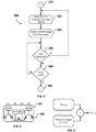
- cylinder skip CS parameter can be modified after each co-fuelling event according to the algorithm presented in FIG. 4 .
- the modified cylinder skip parameter CS mod is determined by adding a random integer selected from the set ⁇ -1,0,1 ⁇ to the default cylinder skip parameter CS default .
- any periodic cylinder roaming co-fuelling sequence that favors some cylinders but not others can be eliminated.
- This technique of modifying the cylinder skip parameter is also beneficial in co-fuelling sequences like the one illustrated in FIGS. 5 and 6 , where even though all cylinders are co-fuelling at some point there is a pattern of firing which may have an associated resonance frequency which can increase engine noise and vibration.
- By randomly modifying the cylinder shift parameter the effect is to introduce noise into the firing pattern such that the effects of resonance frequency are reduced.
- the technique of cylinder roaming co-fuelling is particularly advantageous when the engine is operating in open loop mode where the air-fuel ratio (AFR) is not strictly controlled in a feedback loop.
- Open loop mode can be entered for a variety of reasons, such as for component protection (turbo or catalyst), or when the engine is outside emission control regions in the engine map.
- closed loop mode the amount of directly injected fuel and fumigated fuel introduced into the co-fuelling cylinder is selected such that the residual oxygen left after combustion is equal to the residual oxygen remaining in other non-co-fuelled cylinders to within a predetermined range of tolerance such that an oxygen sensor in the exhaust path provides a consistent signal to the AFR feedback control algorithm.
- Algorithm 500 is entered in step 510 when determined that a fuel system protection technique is required or desirable to protect direct injection system 110, similar to the embodiment of FIG. 2 .
- the steps of 520 through 595 comprise the fuel system protection technique of skip switching. The technique involves co-fuelling the cylinders with fumigated fuel and directly injected fuel as in the technique of cylinder roaming co-fuelling.
- Co-fuelling fuel ratio is selected in step 520 as a function of engine operating conditions.
- fumigated fuel quantity (Q FF ) and directly injected fuel quantity (Q DIF ) are determined as a function of engine operating conditions and the co-fuelling fuel ratio (CFFR).
- step 540 directly injected fuel quantity Q DIF is added to integrated quantity (Q I ) which represents a cumulative quantity of directly injected fuel whose introduction to the cylinder has been delayed.
- Q I integrated quantity
- Integrated quantity (Q I ) is initialized to zero before its first use.
- step 550 integrated quantity (Q I ) is compared with predetermined minimum quantity (Q M ) which represents the minimum quantity of directly injected fuel that can be injected into the combustion chamber in one injection event.
- Q M predetermined minimum quantity
- Fuel injectors are conventionally less accurate in the low fuelling region of operation due to a number of factors. If directly injected fuel quantity (Q DIF ) is in the low fuelling region it is advantageous to store it up over a number of engine cycles until integrated quantity (Q I ) is above the predetermined minimum quantity (Q M ) before introducing it to the combustion chamber.
- step 570 fumigated fuel adjusted quantity (Q FF,Adjusted ) is introduced into the combustion chamber and control is then returned to step 520 for the next engine cycle.
- step 550 when integrated quantity (QI) is not less than predetermined minimum quantity (Q M ) then both fumigated fuel and directly injected fuel are introduced into the co-fuelled cylinder during the current engine cycle.
- step 595 minimum quantity (Q M ) of directly injected fuel and fumigated fuel adjusted quantity (Q FF,Adjusted ) are introduced into the combustion chamber.
- Integrated quantity (Q I ) is reinitialized to the difference between its current value and the predetermined minimum value (Q I - Q M ) and control returns to step 320.
- the technique of skip switching can be adapted and applied to conventional co-fuelling techniques.
- the skip switching fuel system protection technique is ended similarly to the embodiment of FIG. 2 . When controller 250 determines fuel system protection is no longer required the technique of skip switching is ended.
- Algorithm 700 is entered in step 710 when determined that a fuel system protection technique is required or desirable to protect direct injection system 110, similar to the embodiment of FIG. 2 .
- the steps of 720 through 760 comprise the fuel system protection technique of selective enrichment.
- selective enrichment directly injected fuel is employed to decrease the air-fuel ratio (AFR) and increase the equivalence ratio (EQR).
- engine 100 may be running enriched for component protection, such as catalyst protection and turbo protection. Enriching with directly injected fuel has the advantage of increasing the range of fumigated fuel in engine 100 when driven aggressively.
- step 720 an enriched air-fuel ratio is selected as a function of engine operating conditions.
- the enriched air-fuel ratio is already selected since the engine may already be running enriched prior to step 710.
- the co-fuelling fuel ratio (CFFR) is determined as a function of the enriched air-fuel ratio and engine operating conditions. For example, the amount of fumigated fuel selected to be introduced into the cylinder for each combustion cycle is equivalent to the total fuelling quantity required at the current engine operating conditions when engine 100 is not running enriched.
- AFR air-fuel ratio
- CFFR co-fuelling fuel ratio
- the technique of selective enrichment begins by co-fuelling the cylinders according to these ratios.
- Engine operating conditions are monitored in step 740, and control is passed back to step 720 upon a change.
- the controller determines whether fuel system protection is still required or desirable in step 750, and if not the present technique is ended in step 760.
- Algorithm 800 is entered in step 810 when determined that a fuel system protection technique is required or desirable to protect direct injection system 110, similar to the embodiment of FIG. 2 .
- a directly injected fuel monitor is employed to determine in step 810 when a fuel system protection technique is required.
- the fuel monitor tracks the age of directly injected fuel in a fuel vessel in supply system 140. As used herein, "age" is the period of time the fuel has resided in a vessel.
- the likelihood that it will be consumed by engine 100 increases (more co-fuelling), independent of the temperature of direct injector 130.
- the age of the fuel is a function of the time spent in the fuel vessel and the ambient temperature, among other parameters.
- the fuel monitor tracks the filling and emptying of the fuel vessel, vapor management purging algorithms (when the fuel is a liquid fuel), as well as the ambient temperature and makes a determination of the age of the fuel accordingly.
- the fuel monitor can also estimate the degradation of directly injected fuel within direct fuel injector 130.
- the degradation of directly injected fuel in injector 130 is a function of the temperature of the injector.
- the fuel monitor can employ a model that estimates the build-up of deposits inside or on the tip of injector 130 based on the injector temperature. Once the fuel inside the injector degrades past a predetermined quality or once deposits build-up past a predetermined amount then the fuel monitor can signal the controller for increased consumption of directly injected fuel. When the signal is due to deposit build-up within or on direct fuel injector 130, the injection pressure for directly injected fuel can be increased to help remove the deposits.
- step 820 the co-fuelling fuel ratio (CFFR) is selected as a function of the age of the directly injected fuel as well as engine operating conditions, after which all cylinders co-fuel.
- the other fuel system protection techniques described herein can be employed.
- a multiplication factor can be selected to apply to existing co-fuelling maps to increase petrol consumption moving it into a control band where a specific petrol consumption is targeted.
- Engine operating conditions are monitored in step 830, and control is passed back to step 820 upon a change.
- the controller determines whether fuel system protection is still required or desirable in step 840, and if not the present technique is ended in step 850.
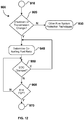
- Algorithm 900 is entered in step 910 when determined that a fuel system protection technique is required or desirable to protect direct injection system 110.
- step 920 it is determined whether a shutdown event or a change in transmission status triggered the entry into algorithm 900 from step 910.
- the change in transmission status can comprise selection of reverse gear, park, neutral, and in standard transmissions de-clutching.
- Other signals that can trigger entry into algorithm 900 comprise driving pattern recognition that correlates a certain driving pattern to a shut-down event.
- step 940 the co-fuelling fuel ratio is selected as a function of the specific event that triggered entry into algorithm 900 (shutdown event, pattern recognition, transmission status change). Engine operating conditions are monitored in step 950 such that control is passed back to step 920 upon a change. The controller determines whether fuel system protection is still required in step 960, and if it is not the present technique is ended in step 970.
- GPS global positioning system
- the fuel system protection techniques described in the embodiments of this disclosure can be selectively combined in other embodiments.
- the different techniques for fuel system protection can be practiced at predetermined regions of the operating map of engine 100, or can be enabled based on other engine operating parameters such as fuel levels or emission levels.
- the techniques practiced herein are fully compliant with regulations in the various fuelling modes.
Landscapes
- Engineering & Computer Science (AREA)
- Chemical & Material Sciences (AREA)
- Combustion & Propulsion (AREA)
- Mechanical Engineering (AREA)
- General Engineering & Computer Science (AREA)
- Oil, Petroleum & Natural Gas (AREA)
- Health & Medical Sciences (AREA)
- Biomedical Technology (AREA)
- Electrical Control Of Air Or Fuel Supplied To Internal-Combustion Engine (AREA)
Description
- The present application relates to a technique of fuel system protection in a multi-fuel system internal combustion engine that operates in a plurality of fuelling modes. In particular, the present application relates to a method of protecting a direct injection fuel injector in a multi-fuel engine with the features of the preamble of
claim 1 and to a corresponding apparatus with the features of the preamble of claim 7. - Natural gas is employed as an alternative fuel for vehicles to replace conventional liquid fuels like gasoline and diesel. There are a number of factors motivating the use of natural gas, of which, two are cost and emissions. On an energy equivalent basis natural gas is less expensive than petroleum based fuels. The price of crude oil continues to increase as production continues to outpace discoveries of new oil reserves. In contrast, the reserves of natural gas continue to increase as production lags behind the discovery of new reserves keeping the price well below oil. Engines fuelled with natural gas produce fewer emissions than engines fuelled with either gasoline or diesel. Due to ever more stringent emission standards engine manufacturers are looking to natural gas to meet these new standards. While the refueling infrastructure for natural gas vehicles is not as extensive as that for conventional liquid fuels, this is a factor that influences adoption of natural gas vehicles especially for consumer automobiles. Access to refueling stations is currently limited to urban areas and main transportation corridors which limits the range of travelling and requires vehicle operators to make planned refueling trips. For these reasons natural gas has had greater adoption in the heavy duty diesel trucking industry since these vehicles typically operate along the natural gas corridor and/or use private refueling facilities. However, due to the above factors motivating the use of natural gas, automobile manufacturers are beginning to integrate natural gas fuel systems alongside existing gasoline fuel systems and to adapt internal combustion engines to be fuelled with more than one fuel, these being referred to in this disclosure as "multi-fuel engines". In this disclosure, the terms "natural gas" and "gas" are used interchangeably and understood to be preferred examples of a gaseous fuel, but that other gaseous fuels such as ethane, methane, propane, biogas, landfill gas, dimethyl ether, hydrogen and mixtures thereof could also be employed instead of natural gas.
- In one such multi-fuel engine there is a direct injection fuel system which introduces liquid fuel directly into combustion chambers, and a natural gas port injection fuel system which introduces natural gas into the intake air upstream of intake valves. In this engine liquid fuel remains dormant in direct fuel injectors that are not being actuated when operating in a port injection natural gas fuelled mode. In this mode, because the nozzles of the direct fuel injectors are located in the combustion chamber it is possible that heat from combustion of port injected fuel elevates the temperature of the liquid fuel inside the direct fuel injectors above a threshold temperature such that the injectors are damaged or carbon deposits begin form. The formation of these carbon deposits leads to fouling of the direct fuel injectors impacting the performance of liquid fuel injection.
- In another engine system there are both liquid fuel direct and port fuel injection systems. Depending upon the current operating mode the engine can be fuelled with either the direct or port fuel injection system or both simultaneously. The liquid fuel that is used to fuel the engine and delivered to the direct and port fuel injection systems can be the same fuel or different fuels if the engine is a multi-fuel engine. For example, when the engine starts it is advantageous to fuel from the direct injection system in a stratified charge mode, and when under high load or speed the engine can fuel from the port injection system in a premixed mode. Direct fuel injectors can become fouled when liquid fuel remains dormant inside while operating the engine with fuel from the port injection system.
-
US 7,853,397 B2 , discloses a method of operating an internal combustion engine that operates with a conventional liquid fuel such as gasoline or ethanol, injected through a high pressure direct injector, and with gas fuel such as natural gas or liquefied petroleum gas introduced into the intake air manifold or ports. In gas fuel operation there is the risk that the high pressure direct injectors heat up due to the lack of through-put of liquid fuel and are subsequently damaged or the fuel located inside forms deposits which have an adverse effect on injector behavior. To avoid these problems, a load characteristic of the high pressure fuel injector is determined and if this load is above a limit value then switchover to liquid fuel operation is performed, or liquid fuel operation is hooked into gas operation such that the liquid fuel in the high pressure injector is purged and the injector is cooled. Based on engine temperatures (operating parameters) a thermal load upon the fuel injector is retrieved from a weighing characteristic map, which is integrated over time to determine the load characteristic value. The method of this patent does not determine the temperature of the high pressure injector, but instead determines stored energy representing the empirical thermal load upon the injector. As a result, during gas operation liquid fuel may be consumed unnecessarily based on the stored energy value even though the temperature of the fuel injector is below a critical value above which deposits begin to form. The method of thispatents determines the thermal load upon the high pressure injector during gas operation only, and does not continuously determine the thermal load for all fuelling modes (gas operation, liquid fuel operation and mixed fuel operation). That is, during gas operation when determined that the thermal load is above the limit value, liquid fuel is flowed through the high pressure fuel injector to purge fuel and cool the injector. The amount of liquid fuel flowed through the injector is based on a predetermined minimum volume, which is expected to cool the injector, instead of the volume required to reduce the temperature of the fuel injector below the critical value at which deposits begin to form. Again, during gas operation, this results in unnecessary and increased liquid fuel operation. - A method and apparatus according to the preamble of the independent claims is disclosed in
US 2008/017171 A1 for a multi-fuel engine that comprises a plurality of cylinders, each cylinder having a combustion chamber. - The state of the art is lacking in techniques for protecting direct injection fuel systems in multi-fuel system engines that reduce or minimize the amount of directly injected fuel that is introduced to protect the direct injection fuel system. Accordingly, for engines that can be fuelled through a direct injection system as well as by means of another fuel system there is a need for an improved method of protecting the direct injection fuel system when operating with the other fuel system.
- The above mentioned object is met in a method comprising the features of the preamble of
claim 1 by the features of the characterising part ofclaim 1. Preferred modifications and improvments of this method are the subject matter of the dependent method-claims 2 to 6. - As the multi-fuel engine comprises a plurality of cylinders, the fuel system protection technique comprises (a) co-fuelling a cylinder corresponding to an ignition firing event with the directly injected fuel and the second fuel; (b) fuelling cylinders corresponding to a predetermined number of subsequent ignition firing events with the second fuel; and (c) repeating steps (a) and (b).
- As the multi-fuel engine comprises a plurality of cylinders, the method may further comprise co-fuelling at least a portion of the plurality of cylinders with the second fuel and the directly injected fuel; delaying introduction of the directly injected fuel when a quantity of the directly injected fuel to introduce in an injection event is below a predetermined value; integrating the quantity of the directly injected fuel; and introducing the directly injected fuel when an integrated quantity is greater than the predetermined value. The second fuel quantity to introduce into the cylinder can be adjusted when introduction of the directly injected fuel into the multi-fuel engine is delayed.
- When the multi-fuel engine at least operates with the second fuel, the fuel system protection technique comprises selecting an enriched air-fuel ratio; selecting a co-fuelling fuel ratio; and introducing or increasing a quantity of the directly injected fuel into the cylinder to operate at the enriched air-fuel ratio.
- The above mentioned object is also met with an apparatus according to claim 7. In this apparatus the electronic controller is further programmed to (a) co-fuel a cylinder corresponding to an ignition firing event with the directly injected fuel and the second fuel; (b) fuel cylinders corresponding to a predetermined number of subsequent ignition firing events with the second fuel; and (c) repeat steps (a) and (b).
- As the multi-fuel engine comprises a plurality of cylinders, the electronic controller is further programmed to co-fuel at least a portion of the plurality of cylinders with the second fuel and the directly injected fuel; delay introduction of the directly injected fuel when a quantity of the directly injected fuel to introduce in an injection event is below a predetermined value; integrate the quantity of the directly injected fuel; and introduce the directly injected fuel when an integrated quantity is greater than the predetermined value.
- When the multi-fuel engine at least operates with the second fuel, the electronic controller is further programmed to select an enriched air-fuel ratio; select a co-fuelling fuel ratio; and introduce or increase a quantity of the directly injected fuel into the cylinder to operate at the enriched air-fuel ratio. In general, the second fuel can be a second directly injected fuel, or can be a fumigated fuel. The second fuel can comprise at least one of methane and natural gas. The directly injected fuel can comprise gasoline and/or ethanol-gasoline blends.
-
-
FIG. 1 is a schematic view of an internal combustion engine according to one embodiment of the present fuel system protection technique. -
FIG. 2 is a flow chart view of a fuel system protection technique according to a first embodiment for the internal combustion engine ofFIG. 1 . -
FIG. 3 is a schematic view of a four cylinder engine for illustrating examples of the fuel system protection technique ofFIG. 2 . -
FIG. 4 is a flow chart view of an algorithm for determining a cylinder skip parameter for the fuel system protection technique ofFIG. 2 . -
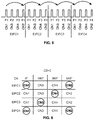
FIG. 5 is a diagrammatic view of an ignition firing event sequence for the internal combustion engine ofFIG.3 according to one example of the fuel system protection technique ofFIG. 2 ; -
FIG. 6 is a tabular view of the diagrammatic view ofFIG.5 showing co-fuelled cylinders during each engine ignition firing cycle. -
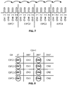
FIG. 7 is a diagrammatic view of an ignition firing event sequence for the internal combustion engine ofFIG. 3 according to another example of the fuel system protection technique ofFIG. 2 . -
FIG. 8 is a tabular view of the diagrammatic view ofFIG. 7 showing co-fuelled cylinders during each engine ignition firing cycle. -
FIG. 9 is a flow chart view of a fuel system protection technique according to a second not claimed embodiment for the internal combustion engine ofFIG. 1 . -
FIG. 10 is a flow chart view of a fuel system protection technique according to a third not claimed embodiment for the internal combustion engine ofFIG. 1 . -
FIG. 11 is a flow chart view of a fuel system protection technique according to a fourth embodiment for the internal combustion engine ofFIG. 1 . -
FIG. 12 is a flow chart view of a fuel system protection technique according to a fifth embodiment for the internal combustion engine ofFIG. 1 . - Referring to the schematic view of
FIG. 1 , there is shown aninternal combustion engine 100 comprising adirect injection system 110 and afumigation system 120.Direct injection system 110 comprises at least onedirect fuel injector 130 andfuel supply system 140.Direct fuel injector 130 is shown centrally located incylinder head 220, which in other embodiments can be side-mounted in a wall ofcylinder block 230. Although only onecombustion chamber 240 is illustrated, in typical embodiments there are a plurality of combustion chambers, and for each combustion chamber there is a respectivedirect fuel injector 130.Fuel supply system 140 supplies fuel toinjector 130 and comprises conventional components found in direct injection systems which can vary depending upon whether the directly injected fuel is a liquid fuel or a gaseous fuel. A gaseous fuel is defined as a fuel that is in a gaseous phase at standard temperature and pressure.Fumigation system 120 comprises conventional components to introduce fuel upstream ofintake valve 190. In the illustration ofFIG. 1 ,fumigation system 120 comprises at least oneport fuel injector 150 andfuel supply system 160. In embodiments where there is more than onecombustion chamber 240, there can be oneport fuel injector 150 for each cylinder, or one fuel injector located further upstream inintake manifold 170 can provide fuel for more than one cylinder. In still further embodiments,fumigation system 120 can comprise conventional components other than fuel injectors for introducing fuel upstream ofintake valve 190, for example mixers.Fuel supply system 160 supplies fuel toinjector 150 and comprises conventional components found in fumigation systems which can vary depending upon whether the fumigated fuel is a liquid fuel or a gaseous fuel.Engine 100 further comprisesexhaust manifold 180. For each cylinder there is anintake valve 190 and anexhaust valve 200.Piston 210 travels within the walls of the cylinder defined bycylinder block 230.Combustion chamber 240 is formed by the space enclosed by the walls of the cylinder,piston 210 andcylinder head 220.Engine 100 further comprises an ignition source (not shown). In a preferred embodiment,engine 100 is spark ignited. In other embodiments, other conventional ignition sources can be employed depending upon system requirements.Electronic controller 250 communicates with and commands bothdirect injection system 110 andfumigation system 120 to deliver fuel for combustion inengine 100. Signal wires represented by the symbols with double arrow heads such as those on the left side ofelectronic controller 250, transmit measured parameters and send command signals for controlling the operation of individual components.Electronic controller 250 can comprise both hardware and software components. The hardware components can comprise digital and/or analog electronic components. In the present exampleelectronic controller 250 comprises a processor and memories, including one or more permanent memories, such as FLASH, EEPROM and a hard disk, and a temporary memory, such as SRAM and DRAM, for storing and executing a program. In another preferred embodimentelectronic controller 250 is an engine control unit (ECU) forengine 100. As used herein,controller 250 is also referred to as 'the controller'. As used herein, the terms algorithm, module, monitor and step refer to an application specific integrated circuit (ASIC), an electronic circuit, a processor (shared, dedicated, or group) and memory that execute one or more software or firmware programs, a combinational logic circuit, and/or other suitable components that provide the described functionality. In preferred embodiments the algorithms, modules and steps herein are part ofelectronic controller 250. -
Engine 100 can operate in multiple fuelling modes comprising a direct injection mode, a fumigated mode and a co-fuelling mode. In the direct injection mode, fuel for combustion inengine 100 is provided bydirect injection system 110. In the fumigated mode fuel for combustion inengine 100 is provided byfumigation system 120, however depending upon engine operating conditions it is possible that fuel is also provided bydirect injection system 120 as will be explained in detail below. In the co-fuelling mode, fuel for combustion is simultaneously provided by bothdirect injection system 110 andfumigation system 120. It is possible thatengine 100 operates in a manner that it can selectively switch between these modes on a per cycle basis. Injection timing can be predetermined responsive to engine operating conditions determined from measured parameters that are inputted intoelectronic controller 250, and the input of such parameters among others is represented byarrow 260. - Referring now to
FIG. 2 , a fuel system protection algorithm that reduces and preferably prevents short term and long term damage to directfuel injector 130 is shown according to a first embodiment.Algorithm 300 is entered instep 310 when it is determined that a fuel system protection technique is required or desirable to protectdirect injection system 110. The determination can be made in several ways, for example by employing a temperature model fordirect fuel injector 130, by integrating the number of combustion cycles or the time spent in fumigated fuel mode, and by engine speed and/or load. The temperature model allows an estimation to be made of the temperature ofdirect fuel injector 130, which has a direct correlation to both short term and long term damage in the injector. For example, the temperature model can be the one disclosed in the Applicant's co-pendingUS Provisional Patent Application No. 61/659,704 fuel supply system 140, detecting a change in transmissions status, an engine shutdown event and driving pattern recognition. The change in transmission status can comprise selection of reverse gear, park, neutral, and in standard transmissions de-clutching. Driving pattern recognition can correlate a certain driving pattern to a shut-down event. For example, employment of a global positioning system (GPS) signal can allow recognition of when the vehicle will be approaching a location where the engine is normally shutdown. This allows proactive measures to be taken to protectdirect injection system 110. - The steps of 320 through 360 comprise the fuel system protection technique of cylinder roaming co-fuelling, which along with other fuel system protection techniques disclosed herein can operate to maintain the temperature of
direct fuel injector 130 below a predetermined value, and to purge dormant fuel withinfuel injector 130 and old fuel fromfuel supply system 140 by flowing directly injected fuel fromsupply system 140 throughinjector 130 intocombustion chamber 240. The technique involves co-fuelling an engine cylinder for one ignition firing event, and repeatedly co-fuelling other engine cylinders after skipping a predetermined number of ignition firing events. By co-fuelling a cylinder which was previously only fuelled with fumigated fuel, the directly injected fuel which has been dormant ininjector 130 can be purged by introducing it into the combustion chamber ofengine 100 such that cooler fuel enters the injector fromfuel system 140 to provide a cooling effect and to cycle fuel throughfuel system 140. The co-fuelled cylinders inengine 100 are alternated with the other cylinders such that over time each of the cylinders is co-fuelled at some point. The cylinder roaming co-fuelling technique requires that introduction of the fumigated fuel into specific cylinders can be controlled. In the presentembodiment fumigation system 120 enables this approach by utilizing port fuel injectors. - Co-fuelling fuel ratio (CFFR) selected in
step 320 according to engine operating conditions represents the ratio of fumigated fuel or directly injected fuel relative to total fuel, and can be stated as the mass fraction of fumigated fuel or the mass fraction of directly injected fuel. The co-fuelling fuel ratio defines the percentage of total fuel which is fumigated fuel and the percentage which is directly injected fuel in the co-fuelling cylinders. Cylinder skip (CS) parameter selected instep 330 represents the number of ignition firing events to skip before co-fuelling another cylinder. As is understood by those familiar with the technology, an ignition firing event is the ignition of fuel within a cylinder.Controller 250 generates a continuous stream of ignition signals that selectively ignite fuel in the cylinders ofengine 100 according a predetermined firing order, as will be explained in more detail below. In other embodiments co-fuelling fuel ratio CFFR and cylinder skip CS parameter can be selected from an engine map according to engine operating conditions and/or according to a desired tip temperature. While the technique of cylinder roaming co-fuelling is operated,controller 250 continuously checks whether engine operating conditions have changed instep 340, and when they have the parameters selected insteps step 350 the controller determines whether fuel system protection is still required or desirable, and if not the technique of cylinder roaming co-fueling is ended instep 360. The determination to end fuel system protection can be due to a variety of factors amongst which are the temperature ofdirect fuel injector 130, a cumulative quantity of directly injected fuel that has been introduced since fuel system protection began instep 310, a cumulative amount of time spent in fuel system protection and a change in engine operating conditions. - Referring now to
FIGS. 3 ,5 and 6 , but first toFIG.3 , an example cylinder roaming co-fuelling sequence is described for a four cylinder engine.Engine 101 comprisescrankshaft 102 operatively connected with cylinders CN1, CN2, CN3 and CN4 such that the firing order of the cylinders is CN1 (F1), CN3 (F2), CN4 (F3), CN2 (F4). That is, the controller repeatedly fires the cylinders (actuates the ignition sources) in this cylinder order, one such cycle is called the engine ignition firing cycle (EIFC) in this disclosure. For a first example, the cylinder skip (CS) parameter selected is 2. With reference toFIGS. 5 and 6 , the first co-fuelling cylinder is CN1 during ignition firing event F1 of engine ignition firing cycle EIFC1. During the induction and compression stroke fumigated fuel and directly injected fuel are introduced into cylinder CN1 according to co-fuelling fuel ratio CFFR. The particular timing of directly injected fuel is application and engine load/speed dependent, and can take place during only the induction stroke, during both the induction and compression stroke, or during only the compression stroke. According to the cylinder skip parameter the next two ignition firing events (F2, F3) are skipped for co-fuelling, and the next co-fuelled cylinder is CN2 during ignition firing event F4 of engine cycle EIFC1. Similarly, the next co-fuelled cylinder is CN4 during ignition firing event F3 of engine ignition firing cycle EIFC2, followed by cylinder CN3 during ignition firing event F2 of engine ignition firing cycle EIFC3. The co-fuelling cycle begins to repeat itself in engine ignition firing cycle EIFC4 in this example, such that all cylinders are co-fuelled during three engine ignition firing cycles. - Referring now to
FIGS. 7 and 8 another co-fuelling sequence is illustrated forengine 101 where the cylinder skip CS parameter selected is 1. As can be seen in the figures, only cylinders CN1 and CN4 are co-fuelled in each engine ignition firing cycle (EIFC1, EIFC2, EIFC3, EIFC4), and cylinders CN3 and CN2 are not co-fuelled. To avoid this situation cylinder skip CS parameter can be modified after each co-fuelling event according to the algorithm presented inFIG. 4 . The modified cylinder skip parameter CSmod is determined by adding a random integer selected from the set {-1,0,1} to the default cylinder skip parameter CSdefault. By randomly modifying cylinder skip CS parameter in this way any periodic cylinder roaming co-fuelling sequence that favors some cylinders but not others can be eliminated. This technique of modifying the cylinder skip parameter is also beneficial in co-fuelling sequences like the one illustrated inFIGS. 5 and 6 , where even though all cylinders are co-fuelling at some point there is a pattern of firing which may have an associated resonance frequency which can increase engine noise and vibration. By randomly modifying the cylinder shift parameter the effect is to introduce noise into the firing pattern such that the effects of resonance frequency are reduced. - The technique of cylinder roaming co-fuelling is particularly advantageous when the engine is operating in open loop mode where the air-fuel ratio (AFR) is not strictly controlled in a feedback loop. Open loop mode can be entered for a variety of reasons, such as for component protection (turbo or catalyst), or when the engine is outside emission control regions in the engine map. In closed loop mode, the amount of directly injected fuel and fumigated fuel introduced into the co-fuelling cylinder is selected such that the residual oxygen left after combustion is equal to the residual oxygen remaining in other non-co-fuelled cylinders to within a predetermined range of tolerance such that an oxygen sensor in the exhaust path provides a consistent signal to the AFR feedback control algorithm.
- Referring now to
FIG. 9 , a fuel system protection algorithm that reduces and preferably prevents short term and long term damage to directfuel injector 130 is shown according to a second embodiment.Algorithm 500 is entered instep 510 when determined that a fuel system protection technique is required or desirable to protectdirect injection system 110, similar to the embodiment ofFIG. 2 . The steps of 520 through 595 comprise the fuel system protection technique of skip switching. The technique involves co-fuelling the cylinders with fumigated fuel and directly injected fuel as in the technique of cylinder roaming co-fuelling. However, in the current technique when an injection quantity of directly injected fuel is below a predetermined minimum value, for example as a result of operating in a specific region of the engine map, then introducing directly injected fuel is delayed and the injection quantity is accumulated from cycle to cycle until the accumulation is greater than the predetermined minimum value after which the predetermined minimum value of directly injected fuel is then introduced into the combustion chamber. In the present disclosure, the accumulated quantity of directly injected fuel is referred to as integrated quantity. Co-fuelling fuel ratio (CFFR) is selected instep 520 as a function of engine operating conditions. Instep 530 fumigated fuel quantity (QFF) and directly injected fuel quantity (QDIF) are determined as a function of engine operating conditions and the co-fuelling fuel ratio (CFFR). These quantities of fuel are to be introduced into the co-fuelled cylinder as discussed for the embodiment ofFIG. 2 , according to the technique now described. Instep 540, directly injected fuel quantity QDIF is added to integrated quantity (QI) which represents a cumulative quantity of directly injected fuel whose introduction to the cylinder has been delayed. The notation '+=' instep 540 is common programming notation that, instep 540, refers to adding the value stored in the variable named QDIF to the value stored in the variable named QI and storing the value in the variable named QI. Integrated quantity (QI) is initialized to zero before its first use. - In
step 550 integrated quantity (QI) is compared with predetermined minimum quantity (QM) which represents the minimum quantity of directly injected fuel that can be injected into the combustion chamber in one injection event. Fuel injectors are conventionally less accurate in the low fuelling region of operation due to a number of factors. If directly injected fuel quantity (QDIF) is in the low fuelling region it is advantageous to store it up over a number of engine cycles until integrated quantity (QI) is above the predetermined minimum quantity (QM) before introducing it to the combustion chamber. Instep 550, when integrated quantity (QI) is less than predetermined minimum quantity (QM) directly injected fuel is not injected during the current engine cycle and control passes to step 560 where fumigated fuel quantity (QFF) is adjusted to equal the total quantity of fuel (QFF,Adjusted= QFF+QDIF) on an energy equivalent basis since only fumigated fuel will be introduced into the combustion chamber in the current engine cycle. Instep 570 fumigated fuel adjusted quantity (QFF,Adjusted) is introduced into the combustion chamber and control is then returned to step 520 for the next engine cycle. - Returning to step 550, when integrated quantity (QI) is not less than predetermined minimum quantity (QM) then both fumigated fuel and directly injected fuel are introduced into the co-fuelled cylinder during the current engine cycle. In step 580 a determination is made as to whether integrated quantity (QI) represents a cumulative total for the current co-fuelled engine cycle (QI=QDIF) or for a number of co-fuelled engine cycles (QI>QDIF). When the integrated quantity (QI) represents a cumulative total for a number of co-fuelled engine cycles control passes to step 590 where the quantity of fumigated fuel is adjusted such that (QM +OFF,Adjusted)=(QDIF + QFF) on an energy equivalent basis. In
step 595 minimum quantity (QM) of directly injected fuel and fumigated fuel adjusted quantity (QFF,Adjusted) are introduced into the combustion chamber. Integrated quantity (QI) is reinitialized to the difference between its current value and the predetermined minimum value (QI - QM) and control returns to step 320. The notation '-=' instep 595 is common programming notation that, instep 595, refers to subtracting the value stored in the variable named QM from the value stored in the variable named QI and storing the value in the variable named QI. By reinitializing integrated quantity to the difference between integrated quantity and minimum quantity the probability of periodic introductions of fumigated fuel and directly injectedfuel according step 595 favoring the same cylinder is reduced, which increases the probability of a performingstep 595 with a different cylinder the next time. - Returning again to step 580, when integrated quantity (QI) represents a total for the current co-fuelled engine cycle (QI=QDIF) control passes to step 585 where fumigated fuel quantity (QFF) and integrated quantity (QI) of directly injected fuel are introduced into the combustion chamber. Integrated quantity (QI) is reinitialized to zero and control returns to step 520. Although the above algorithm has been described as a refinement of the technique of cylinder roaming co-fuelling, the technique of skip switching can be adapted and applied to conventional co-fuelling techniques. The skip switching fuel system protection technique is ended similarly to the embodiment of
FIG. 2 . Whencontroller 250 determines fuel system protection is no longer required the technique of skip switching is ended. - Referring now to
FIG. 10 , a fuel system protection algorithm that reduces and preferably prevents short term and long term damage to directfuel injector 130 is shown according to a third embodiment.Algorithm 700 is entered instep 710 when determined that a fuel system protection technique is required or desirable to protectdirect injection system 110, similar to the embodiment ofFIG. 2 . The steps of 720 through 760 comprise the fuel system protection technique of selective enrichment. In selective enrichment directly injected fuel is employed to decrease the air-fuel ratio (AFR) and increase the equivalence ratio (EQR). As an example,engine 100 may be running enriched for component protection, such as catalyst protection and turbo protection. Enriching with directly injected fuel has the advantage of increasing the range of fumigated fuel inengine 100 when driven aggressively. Instep 720 an enriched air-fuel ratio is selected as a function of engine operating conditions. In some circumstances the enriched air-fuel ratio is already selected since the engine may already be running enriched prior to step 710. Instep 730 the co-fuelling fuel ratio (CFFR) is determined as a function of the enriched air-fuel ratio and engine operating conditions. For example, the amount of fumigated fuel selected to be introduced into the cylinder for each combustion cycle is equivalent to the total fuelling quantity required at the current engine operating conditions whenengine 100 is not running enriched. After selecting the air-fuel ratio (AFR) and co-fuelling fuel ratio (CFFR) the technique of selective enrichment begins by co-fuelling the cylinders according to these ratios. Engine operating conditions are monitored instep 740, and control is passed back to step 720 upon a change. The controller determines whether fuel system protection is still required or desirable instep 750, and if not the present technique is ended instep 760. - Referring now to
FIG. 11 , a fuel system protection algorithm that reduces and preferably prevents short term and long term damage to directfuel injector 130 is shown according to a fourth embodiment.Algorithm 800 is entered instep 810 when determined that a fuel system protection technique is required or desirable to protectdirect injection system 110, similar to the embodiment ofFIG. 2 . In addition to the embodiment ofFIG. 2 , a directly injected fuel monitor is employed to determine instep 810 when a fuel system protection technique is required. The fuel monitor tracks the age of directly injected fuel in a fuel vessel insupply system 140. As used herein, "age" is the period of time the fuel has resided in a vessel. After the fuel in the vessel reaches a predetermined age the likelihood that it will be consumed byengine 100 increases (more co-fuelling), independent of the temperature ofdirect injector 130. The age of the fuel is a function of the time spent in the fuel vessel and the ambient temperature, among other parameters. The fuel monitor tracks the filling and emptying of the fuel vessel, vapor management purging algorithms (when the fuel is a liquid fuel), as well as the ambient temperature and makes a determination of the age of the fuel accordingly. The fuel monitor can also estimate the degradation of directly injected fuel withindirect fuel injector 130. The degradation of directly injected fuel ininjector 130 is a function of the temperature of the injector. In addition, the fuel monitor can employ a model that estimates the build-up of deposits inside or on the tip ofinjector 130 based on the injector temperature. Once the fuel inside the injector degrades past a predetermined quality or once deposits build-up past a predetermined amount then the fuel monitor can signal the controller for increased consumption of directly injected fuel. When the signal is due to deposit build-up within or ondirect fuel injector 130, the injection pressure for directly injected fuel can be increased to help remove the deposits. - In
step 820 the co-fuelling fuel ratio (CFFR) is selected as a function of the age of the directly injected fuel as well as engine operating conditions, after which all cylinders co-fuel. In other embodiments, the other fuel system protection techniques described herein can be employed. As an alternative to selecting a co-fuelling fuel ratio isstep 820, a multiplication factor can be selected to apply to existing co-fuelling maps to increase petrol consumption moving it into a control band where a specific petrol consumption is targeted. Engine operating conditions are monitored instep 830, and control is passed back to step 820 upon a change. The controller determines whether fuel system protection is still required or desirable instep 840, and if not the present technique is ended instep 850. - Referring now to
FIG. 12 , a fuel system protection algorithm that reduces and preferably prevents short term and long term damage to directfuel injector 130 is shown according to a fifth embodiment.Algorithm 900 is entered instep 910 when determined that a fuel system protection technique is required or desirable to protectdirect injection system 110. Instep 920 it is determined whether a shutdown event or a change in transmission status triggered the entry intoalgorithm 900 fromstep 910. The change in transmission status can comprise selection of reverse gear, park, neutral, and in standard transmissions de-clutching. Other signals that can trigger entry intoalgorithm 900 comprise driving pattern recognition that correlates a certain driving pattern to a shut-down event. For example, employment of a global positioning system (GPS) signal can allow recognition of when the vehicle will be approaching a location where the engine is normally shutdown. This allows proactive measures to be taken to protectdirect injection system 110. Instep 940 the co-fuelling fuel ratio is selected as a function of the specific event that triggered entry into algorithm 900 (shutdown event, pattern recognition, transmission status change). Engine operating conditions are monitored instep 950 such that control is passed back to step 920 upon a change. The controller determines whether fuel system protection is still required instep 960, and if it is not the present technique is ended instep 970. - The fuel system protection techniques described in the embodiments of this disclosure can be selectively combined in other embodiments. In the combined algorithms, the different techniques for fuel system protection can be practiced at predetermined regions of the operating map of
engine 100, or can be enabled based on other engine operating parameters such as fuel levels or emission levels. The techniques practiced herein are fully compliant with regulations in the various fuelling modes. - While particular elements, embodiments and applications of the present invention have been shown and described, it will be understood, that the invention is not limited thereto since modifications can be made by those skilled in the art without departing from the scope of the claims.
Claims (8)
- A method of protecting a direct injection fuel injector in a multi-fuel engine, that comprises a plurality of cylinders,
said method comprising:selectively operating said multi-fuel engine with a directly injected fuel introduced through said direct injection fuel injector and/or with a second fuel, andwhen fuelling said multi-fuel engine with said second fuel, selectively commanding a fuel system protection technique when determining that at least one of said direct injection fuel injectors requires cooling,wherein said fuel system protection technique comprises commanding that said directly injected fuel be a portion of total fuel consumed and reducing the quantity of said second fuel that is injected so that total fuel consumed equals a desired amount of fuel measured on an energy basis,wherein said determining is based on at least one of the following inputs:a temperature model for said direct injection fuel injector,an age of directly injected fuel is above a predetermined value,a transmission status has changed,an engine shutdown event has occurred,a driving pattern recognition predicts an engine shutdown event will occur.characterized in thatsaid fuel system protection technique comprises:(a) co-fuelling one cylinder of said plurality of cylinders corresponding to an ignition firing event with said directly injected fuel and said second fuel, and fuelling the remaining of said plurality of cylinders with only said second fuel,(b) fuelling said plurality of cylinders corresponding to a predetermined number of subsequent ignition firing events with only said second fuel, and(c) repeating steps (a) and (b), wherein said cylinder that is co-fuelled is alternated with other ones of said plurality of cylinders whereby over time each cylinder is co-fuelled. - The method of claim 1, characterized in that
it further comprises the following features:(i) selecting a co-fuelling fuel ratio based on a desired tip temperature of said direct injection fuel injector; and/or(ii) selecting said predetermined number of subsequent ignition firing events based on said desired tip temperature of said direct injection fuel injector. - The method of claim 1, characterized in that
it further comprises the following features:selecting said predetermined number of subsequent ignition firing events;selecting a random number from a set of integers; andmodifying said predetermined number of subsequent ignition firing events based on a function of said random number;wherein periodic favoring of co-fuelling one cylinder compared to other cylinders is reduced. - The method of claim 3, characterized in that
said predetermined number of subsequent ignition firing events is modified after co-fuelled ignition firing events. - The method of any one of the claims 1 to 4, characterized in that said second fuel(i) is a second directly injected fuel, or(ii) is a fumigated fuel, or(iii) comprises at least one of methane and natural gas.
- The method of any one of the claims 1 to 5, characterized in that said directly injected fuel comprises gasoline or ethanol-gasoline blends.
- An apparatus for protecting a fuel system in a multi-fuel engine that comprises a plurality of cylinders (CN), wherein each cylinder (CN) has a combustion chamber (240),
the apparatus comprising:a direct fuel injector (130) for introducing a directly injected fuel into a combustion chamber (240) of said multi-fuel engine,a second injector (150) for introducing a second fuel, andan electronic controller (250),wherein the electronic controller (250) is programmed toselectively operate said multi-fuel engine with said directly injected fuel and/or with said second fuel,when fuelling said multi-fuel engine with said second fuel, selectively command a fuel system protection technique when determining that at least one of said direct injection fuel injectors requires cooling, andcommands said fuel system protection technique comprising that said directly injected fuel be a portion of total fuel consumed and reduce the quantity of said second fuel that is injected so that total fuel consumed equals a desired amount of fuel measured on an energy basis,wherein said electronic controller (250) is also programmed to determine that at least one of said direct injection fuel injectors (130) requires cooling based on at least one of the following inputs:a temperature model for said direct injection fuel injector,an age of directly injected fuel is above a predetermined value,a transmission status has changed,an engine shutdown event has occurred,a driving pattern recognition predicts an engine shutdown event will occur,characterized in that,said electronic controller (250) is further programmed to:(a) co-fuel a cylinder (CN) of said plurality of cylinders (CN) corresponding to an ignition firing event with said directly injected fuel and said second fuel, and fuel the remaining of said plurality of cylinders (CN) with only said second fuel,(b) fuel said plurality of cylinders corresponding (CN) to a predetermined number of subsequent ignition firing events with only said second fuel, and(c) repeat steps (a) and (b) wherein said cylinder (CN) that is co-fuelled is alternated with other ones of said plurality of cylinders (CN) whereby over time each cylinder (CN) is co-fuelled. - The apparatus of claim 7, characterized in that
it further comprises a fumigation system for introducing a fumigated fuel upstream of an intake valve of said combustion chamber; wherein said second fuel is said fumigated fuel and said second injector introduces said fumigated fuel.
Applications Claiming Priority (2)
| Application Number | Priority Date | Filing Date | Title |
|---|---|---|---|
| US201261711685P | 2012-10-09 | 2012-10-09 | |
| PCT/CA2013/050757 WO2014056103A1 (en) | 2012-10-09 | 2013-10-08 | Fuel system protection in a multi-fuel internal combustion engine |
Publications (3)
| Publication Number | Publication Date |
|---|---|
| EP2906799A1 EP2906799A1 (en) | 2015-08-19 |
| EP2906799A4 EP2906799A4 (en) | 2016-08-03 |
| EP2906799B1 true EP2906799B1 (en) | 2019-03-27 |
Family
ID=50476830
Family Applications (1)
| Application Number | Title | Priority Date | Filing Date |
|---|---|---|---|
| EP13845933.4A Active EP2906799B1 (en) | 2012-10-09 | 2013-10-08 | Fuel system protection in a multi-fuel internal combustion engine |
Country Status (4)
| Country | Link |
|---|---|
| US (1) | US9624864B2 (en) |
| EP (1) | EP2906799B1 (en) |
| CN (1) | CN104838113B (en) |
| WO (1) | WO2014056103A1 (en) |
Cited By (1)
| Publication number | Priority date | Publication date | Assignee | Title |
|---|---|---|---|---|
| US12215640B2 (en) | 2023-05-23 | 2025-02-04 | Caterpillar Inc. | Systems and methods for purging fuel in a combustion engine |
Families Citing this family (11)
| Publication number | Priority date | Publication date | Assignee | Title |
|---|---|---|---|---|
| MX343431B (en) * | 2011-10-28 | 2016-11-03 | Eht P And L Ltd | Improvement of a combustion engine. |
| EP2861852B1 (en) * | 2012-06-14 | 2018-04-04 | Westport Power Inc. | Fuel system protection in a multi-fuel system internal combustion engine |
| US9506408B2 (en) * | 2014-06-02 | 2016-11-29 | Ford Global Technologies, Llc | Method of fuel injection for a variable displacement engine |
| US10202910B2 (en) * | 2014-07-07 | 2019-02-12 | Ford Global Technologies, Llc | System and method for selective cylinder deactivation |
| US10316773B2 (en) * | 2015-06-11 | 2019-06-11 | Ford Global Technologies, Llc | Methods and system mitigating port injection degradation |
| KR20170026685A (en) * | 2015-08-26 | 2017-03-09 | 현대자동차주식회사 | Fuel management system for hybrid vehicle |
| WO2017031598A1 (en) * | 2015-08-27 | 2017-03-02 | Westport Power Inc. | Deposit mitigation for gaseous fuel injectors |
| PL239368B1 (en) * | 2016-02-04 | 2021-11-29 | Ac Spolka Akcyjna | System for adaptation of liquid fuel internal combustion engine to the supply with gaseous fuel in the gaseous phase and with gaseous fuel in liquid phase, the engine arrangement containing that system and method for its adaptation for the supply with gaseous fuel in the gaseous phase and with gaseous fuel in liquid phase |
| US10100761B2 (en) * | 2017-02-17 | 2018-10-16 | Ford Global Technologies, Llc | Method and system for selective cylinder deactivation |
| CA3068150C (en) * | 2017-07-28 | 2022-07-19 | Ac S.A. | System for adapting an internal combustion engine to be powered by gaseous fuel in gas phase and by gaseous fuel in liquid phase |
| US10145319B1 (en) | 2018-01-23 | 2018-12-04 | Caterpillar Inc. | Control strategy for improved substitution capability in dual fuel engine system |
Citations (1)
| Publication number | Priority date | Publication date | Assignee | Title |
|---|---|---|---|---|
| US20120102925A1 (en) * | 2008-05-15 | 2012-05-03 | Ford Global Technologies, Llc | Engine exhaust temperature regulation |
Family Cites Families (17)
| Publication number | Priority date | Publication date | Assignee | Title |
|---|---|---|---|---|
| DE3129078A1 (en) * | 1981-07-23 | 1983-02-03 | Daimler-Benz Ag, 7000 Stuttgart | METHOD FOR THE INTERRUPTION CONTROL OF A PERIODICALLY WORKING INTERNAL COMBUSTION ENGINE |
| US4463734A (en) * | 1982-05-14 | 1984-08-07 | Akeroyd Richard T | Dual fuel diesel engine |
| US5937800A (en) * | 1998-03-06 | 1999-08-17 | Caterpillar Inc. | Method for enabling a substantially constant total fuel energy rate within a dual fuel engine |
| WO2001086128A2 (en) * | 2000-05-08 | 2001-11-15 | Cummins, Inc. | Internal combustion engine operable in pcci mode with early control injection and method of operation |
| DE10318963A1 (en) * | 2003-04-26 | 2004-11-11 | Adam Opel Ag | Internal combustion engine for operation with two different anti-knock fuels |
| CA2442601C (en) * | 2003-09-26 | 2005-05-24 | Westport Research Inc. | A fuel injection system and method of operation for a gaseous fuelled engine with liquid pilot fuel ignition |
| JP4135642B2 (en) * | 2004-01-13 | 2008-08-20 | トヨタ自動車株式会社 | Injection control device for internal combustion engine |
| US7681554B2 (en) * | 2006-07-24 | 2010-03-23 | Ford Global Technologies, Llc | Approach for reducing injector fouling and thermal degradation for a multi-injector engine system |
| DE102006054463A1 (en) * | 2006-11-18 | 2008-05-21 | Daimler Ag | Bivalent, spark-ignition internal combustion engine i.e. four-cylinder engine, operating method, involves injecting liquid and gaseous fuel in selected operating area of engine and implementing operation of engine with fuel |
| DE102006056389A1 (en) | 2006-11-29 | 2008-06-05 | Audi Ag | Operating method for an optionally operable with liquid and gaseous fuel internal combustion engine and fuel supply system |
| DE102007025075A1 (en) | 2007-05-30 | 2008-12-04 | Volkswagen Ag | Method for operating an internal combustion engine |
| DE102007025076A1 (en) * | 2007-05-30 | 2008-12-04 | Volkswagen Ag | Method for operating an internal combustion engine |
| US20090090332A1 (en) * | 2007-10-03 | 2009-04-09 | Brehob Diana D | Method and System to Mitigate Deposit Formation on a Direct Injector for a Gasoline-Fuelled Internal Combustion Engine |
| DE102007050305A1 (en) * | 2007-10-22 | 2009-04-23 | Robert Bosch Gmbh | Method and apparatus for operating an internal combustion engine with two types of fuel |
| US8118006B2 (en) * | 2010-04-08 | 2012-02-21 | Ford Global Technologies, Llc | Fuel injector diagnostic for dual fuel engine |
| CA2807879C (en) * | 2010-08-16 | 2018-12-04 | Westport Power Inc. | Gaseous-fuelled stoichiometric compression ignition internal combustion engine |
| US8534263B2 (en) * | 2011-01-12 | 2013-09-17 | GM Global Technology Operations LLC | Bi-fuel engine including system and method for reducing component temperature |
-
2013
- 2013-10-08 EP EP13845933.4A patent/EP2906799B1/en active Active
- 2013-10-08 WO PCT/CA2013/050757 patent/WO2014056103A1/en not_active Ceased
- 2013-10-08 CN CN201380064140.9A patent/CN104838113B/en active Active
-
2015
- 2015-04-03 US US14/678,694 patent/US9624864B2/en active Active
Patent Citations (1)
| Publication number | Priority date | Publication date | Assignee | Title |
|---|---|---|---|---|
| US20120102925A1 (en) * | 2008-05-15 | 2012-05-03 | Ford Global Technologies, Llc | Engine exhaust temperature regulation |
Cited By (1)
| Publication number | Priority date | Publication date | Assignee | Title |
|---|---|---|---|---|
| US12215640B2 (en) | 2023-05-23 | 2025-02-04 | Caterpillar Inc. | Systems and methods for purging fuel in a combustion engine |
Also Published As
| Publication number | Publication date |
|---|---|
| CN104838113A (en) | 2015-08-12 |
| EP2906799A1 (en) | 2015-08-19 |
| US20150275813A1 (en) | 2015-10-01 |
| EP2906799A4 (en) | 2016-08-03 |
| CN104838113B (en) | 2018-05-11 |
| WO2014056103A1 (en) | 2014-04-17 |
| US9624864B2 (en) | 2017-04-18 |
Similar Documents
| Publication | Publication Date | Title |
|---|---|---|
| US9624864B2 (en) | Fuel system protection in a multi-fuel internal combustion engine | |
| US9476367B2 (en) | Fuel system protection in a multi-fuel engine | |
| US9856837B2 (en) | Apparatus and method for fuelling a flexible-fuel internal combustion engine | |
| US9909513B2 (en) | Fuel system protection in a multi-fuel system internal combustion engine | |
| JP4103867B2 (en) | Control device for hydrogenated internal combustion engine | |
| US7853397B2 (en) | Method of operating an internal combustion engine | |
| US7832381B2 (en) | Method of operating an internal combustion engine | |
| KR100902958B1 (en) | Exhaust Gas Control System and Control Method for Diesel-Gas Mixture Engine | |
| US8955499B2 (en) | Exhaust gas recirculation device | |
| US10047692B2 (en) | GDCI cold start misfire prevention | |
| JP2009121364A (en) | Fuel injection control device | |
| JP2003232234A (en) | Fuel supply control device for internal combustion engine | |
| JP5867441B2 (en) | Control device for internal combustion engine | |
| JP4305150B2 (en) | Internal combustion engine | |
| JP5731735B2 (en) | Engine control device | |
| JP2011169273A (en) | Internal combustion engine | |
| JP2008121690A (en) | Control device for hydrogenated internal combustion engine | |
| WO2012168793A1 (en) | Control unit and control method for internal combustion engine | |
| JP2006132490A (en) | Hydrogenated internal combustion engine | |
| JP2004324509A (en) | Fuel injection control method and ignition timing control method for LPG fuel engine | |
| JP2005248813A (en) | Liquefied gas fuel engine | |
| JP2016125453A (en) | Fuel injection control device of internal combustion engine | |
| JP2017133396A (en) | Bi-fuel engine system |
Legal Events
| Date | Code | Title | Description |
|---|---|---|---|
| PUAI | Public reference made under article 153(3) epc to a published international application that has entered the european phase |
Free format text: ORIGINAL CODE: 0009012 |
|
| 17P | Request for examination filed |
Effective date: 20150429 |
|
| AK | Designated contracting states |
Kind code of ref document: A1 Designated state(s): AL AT BE BG CH CY CZ DE DK EE ES FI FR GB GR HR HU IE IS IT LI LT LU LV MC MK MT NL NO PL PT RO RS SE SI SK SM TR |
|
| AX | Request for extension of the european patent |
Extension state: BA ME |
|
| DAX | Request for extension of the european patent (deleted) | ||
| RA4 | Supplementary search report drawn up and despatched (corrected) |
Effective date: 20160701 |
|
| RIC1 | Information provided on ipc code assigned before grant |
Ipc: F02D 41/30 20060101ALI20160627BHEP Ipc: F02D 19/08 20060101AFI20160627BHEP Ipc: F02D 41/00 20060101ALI20160627BHEP Ipc: F02D 19/06 20060101ALI20160627BHEP Ipc: F02D 41/38 20060101ALI20160627BHEP |
|
| STAA | Information on the status of an ep patent application or granted ep patent |
Free format text: STATUS: EXAMINATION IS IN PROGRESS |
|
| 17Q | First examination report despatched |
Effective date: 20170703 |
|
| REG | Reference to a national code |
Ref country code: DE Ref legal event code: R079 Ref document number: 602013053086 Country of ref document: DE Free format text: PREVIOUS MAIN CLASS: F02D0019080000 Ipc: F02D0019060000 |
|
| GRAP | Despatch of communication of intention to grant a patent |
Free format text: ORIGINAL CODE: EPIDOSNIGR1 |
|
| RIC1 | Information provided on ipc code assigned before grant |
Ipc: F02D 41/30 20060101ALI20180830BHEP Ipc: F02D 41/22 20060101ALI20180830BHEP Ipc: F02D 41/00 20060101ALI20180830BHEP Ipc: F02D 19/08 20060101ALI20180830BHEP Ipc: F02D 19/06 20060101AFI20180830BHEP Ipc: F02D 41/38 20060101ALI20180830BHEP |
|
| STAA | Information on the status of an ep patent application or granted ep patent |
Free format text: STATUS: GRANT OF PATENT IS INTENDED |
|
| INTG | Intention to grant announced |
Effective date: 20181004 |
|
| GRAS | Grant fee paid |
Free format text: ORIGINAL CODE: EPIDOSNIGR3 |
|
| GRAA | (expected) grant |
Free format text: ORIGINAL CODE: 0009210 |
|
| STAA | Information on the status of an ep patent application or granted ep patent |
Free format text: STATUS: THE PATENT HAS BEEN GRANTED |
|
| AK | Designated contracting states |
Kind code of ref document: B1 Designated state(s): AL AT BE BG CH CY CZ DE DK EE ES FI FR GB GR HR HU IE IS IT LI LT LU LV MC MK MT NL NO PL PT RO RS SE SI SK SM TR |
|
| REG | Reference to a national code |
Ref country code: GB Ref legal event code: FG4D |
|
| REG | Reference to a national code |
Ref country code: CH Ref legal event code: EP |
|
| REG | Reference to a national code |
Ref country code: AT Ref legal event code: REF Ref document number: 1113377 Country of ref document: AT Kind code of ref document: T Effective date: 20190415 |
|
| REG | Reference to a national code |
Ref country code: IE Ref legal event code: FG4D |
|
| REG | Reference to a national code |
Ref country code: DE Ref legal event code: R096 Ref document number: 602013053086 Country of ref document: DE |
|
| PG25 | Lapsed in a contracting state [announced via postgrant information from national office to epo] |
Ref country code: FI Free format text: LAPSE BECAUSE OF FAILURE TO SUBMIT A TRANSLATION OF THE DESCRIPTION OR TO PAY THE FEE WITHIN THE PRESCRIBED TIME-LIMIT Effective date: 20190327 Ref country code: NO Free format text: LAPSE BECAUSE OF FAILURE TO SUBMIT A TRANSLATION OF THE DESCRIPTION OR TO PAY THE FEE WITHIN THE PRESCRIBED TIME-LIMIT Effective date: 20190627 Ref country code: SE Free format text: LAPSE BECAUSE OF FAILURE TO SUBMIT A TRANSLATION OF THE DESCRIPTION OR TO PAY THE FEE WITHIN THE PRESCRIBED TIME-LIMIT Effective date: 20190327 Ref country code: LT Free format text: LAPSE BECAUSE OF FAILURE TO SUBMIT A TRANSLATION OF THE DESCRIPTION OR TO PAY THE FEE WITHIN THE PRESCRIBED TIME-LIMIT Effective date: 20190327 |
|
| REG | Reference to a national code |
Ref country code: NL Ref legal event code: MP Effective date: 20190327 |
|
| PG25 | Lapsed in a contracting state [announced via postgrant information from national office to epo] |
Ref country code: LV Free format text: LAPSE BECAUSE OF FAILURE TO SUBMIT A TRANSLATION OF THE DESCRIPTION OR TO PAY THE FEE WITHIN THE PRESCRIBED TIME-LIMIT Effective date: 20190327 Ref country code: RS Free format text: LAPSE BECAUSE OF FAILURE TO SUBMIT A TRANSLATION OF THE DESCRIPTION OR TO PAY THE FEE WITHIN THE PRESCRIBED TIME-LIMIT Effective date: 20190327 Ref country code: HR Free format text: LAPSE BECAUSE OF FAILURE TO SUBMIT A TRANSLATION OF THE DESCRIPTION OR TO PAY THE FEE WITHIN THE PRESCRIBED TIME-LIMIT Effective date: 20190327 Ref country code: NL Free format text: LAPSE BECAUSE OF FAILURE TO SUBMIT A TRANSLATION OF THE DESCRIPTION OR TO PAY THE FEE WITHIN THE PRESCRIBED TIME-LIMIT Effective date: 20190327 Ref country code: BG Free format text: LAPSE BECAUSE OF FAILURE TO SUBMIT A TRANSLATION OF THE DESCRIPTION OR TO PAY THE FEE WITHIN THE PRESCRIBED TIME-LIMIT Effective date: 20190627 Ref country code: GR Free format text: LAPSE BECAUSE OF FAILURE TO SUBMIT A TRANSLATION OF THE DESCRIPTION OR TO PAY THE FEE WITHIN THE PRESCRIBED TIME-LIMIT Effective date: 20190628 |
|
| REG | Reference to a national code |
Ref country code: AT Ref legal event code: MK05 Ref document number: 1113377 Country of ref document: AT Kind code of ref document: T Effective date: 20190327 |
|
| PG25 | Lapsed in a contracting state [announced via postgrant information from national office to epo] |
Ref country code: EE Free format text: LAPSE BECAUSE OF FAILURE TO SUBMIT A TRANSLATION OF THE DESCRIPTION OR TO PAY THE FEE WITHIN THE PRESCRIBED TIME-LIMIT Effective date: 20190327 Ref country code: IT Free format text: LAPSE BECAUSE OF FAILURE TO SUBMIT A TRANSLATION OF THE DESCRIPTION OR TO PAY THE FEE WITHIN THE PRESCRIBED TIME-LIMIT Effective date: 20190327 Ref country code: CZ Free format text: LAPSE BECAUSE OF FAILURE TO SUBMIT A TRANSLATION OF THE DESCRIPTION OR TO PAY THE FEE WITHIN THE PRESCRIBED TIME-LIMIT Effective date: 20190327 Ref country code: SK Free format text: LAPSE BECAUSE OF FAILURE TO SUBMIT A TRANSLATION OF THE DESCRIPTION OR TO PAY THE FEE WITHIN THE PRESCRIBED TIME-LIMIT Effective date: 20190327 Ref country code: PT Free format text: LAPSE BECAUSE OF FAILURE TO SUBMIT A TRANSLATION OF THE DESCRIPTION OR TO PAY THE FEE WITHIN THE PRESCRIBED TIME-LIMIT Effective date: 20190727 Ref country code: AL Free format text: LAPSE BECAUSE OF FAILURE TO SUBMIT A TRANSLATION OF THE DESCRIPTION OR TO PAY THE FEE WITHIN THE PRESCRIBED TIME-LIMIT Effective date: 20190327 Ref country code: RO Free format text: LAPSE BECAUSE OF FAILURE TO SUBMIT A TRANSLATION OF THE DESCRIPTION OR TO PAY THE FEE WITHIN THE PRESCRIBED TIME-LIMIT Effective date: 20190327 Ref country code: ES Free format text: LAPSE BECAUSE OF FAILURE TO SUBMIT A TRANSLATION OF THE DESCRIPTION OR TO PAY THE FEE WITHIN THE PRESCRIBED TIME-LIMIT Effective date: 20190327 |
|
| PG25 | Lapsed in a contracting state [announced via postgrant information from national office to epo] |
Ref country code: SM Free format text: LAPSE BECAUSE OF FAILURE TO SUBMIT A TRANSLATION OF THE DESCRIPTION OR TO PAY THE FEE WITHIN THE PRESCRIBED TIME-LIMIT Effective date: 20190327 Ref country code: PL Free format text: LAPSE BECAUSE OF FAILURE TO SUBMIT A TRANSLATION OF THE DESCRIPTION OR TO PAY THE FEE WITHIN THE PRESCRIBED TIME-LIMIT Effective date: 20190327 |
|
| PG25 | Lapsed in a contracting state [announced via postgrant information from national office to epo] |
Ref country code: AT Free format text: LAPSE BECAUSE OF FAILURE TO SUBMIT A TRANSLATION OF THE DESCRIPTION OR TO PAY THE FEE WITHIN THE PRESCRIBED TIME-LIMIT Effective date: 20190327 Ref country code: IS Free format text: LAPSE BECAUSE OF FAILURE TO SUBMIT A TRANSLATION OF THE DESCRIPTION OR TO PAY THE FEE WITHIN THE PRESCRIBED TIME-LIMIT Effective date: 20190727 |
|
| REG | Reference to a national code |
Ref country code: DE Ref legal event code: R097 Ref document number: 602013053086 Country of ref document: DE |
|
| PG25 | Lapsed in a contracting state [announced via postgrant information from national office to epo] |
Ref country code: DK Free format text: LAPSE BECAUSE OF FAILURE TO SUBMIT A TRANSLATION OF THE DESCRIPTION OR TO PAY THE FEE WITHIN THE PRESCRIBED TIME-LIMIT Effective date: 20190327 |
|
| PLBE | No opposition filed within time limit |
Free format text: ORIGINAL CODE: 0009261 |
|
| STAA | Information on the status of an ep patent application or granted ep patent |
Free format text: STATUS: NO OPPOSITION FILED WITHIN TIME LIMIT |
|
| PG25 | Lapsed in a contracting state [announced via postgrant information from national office to epo] |
Ref country code: SI Free format text: LAPSE BECAUSE OF FAILURE TO SUBMIT A TRANSLATION OF THE DESCRIPTION OR TO PAY THE FEE WITHIN THE PRESCRIBED TIME-LIMIT Effective date: 20190327 |
|
| 26N | No opposition filed |
Effective date: 20200103 |
|
| PG25 | Lapsed in a contracting state [announced via postgrant information from national office to epo] |
Ref country code: TR Free format text: LAPSE BECAUSE OF FAILURE TO SUBMIT A TRANSLATION OF THE DESCRIPTION OR TO PAY THE FEE WITHIN THE PRESCRIBED TIME-LIMIT Effective date: 20190327 |
|
| PG25 | Lapsed in a contracting state [announced via postgrant information from national office to epo] |
Ref country code: MC Free format text: LAPSE BECAUSE OF FAILURE TO SUBMIT A TRANSLATION OF THE DESCRIPTION OR TO PAY THE FEE WITHIN THE PRESCRIBED TIME-LIMIT Effective date: 20190327 |
|
| REG | Reference to a national code |
Ref country code: CH Ref legal event code: PL |
|
| PG25 | Lapsed in a contracting state [announced via postgrant information from national office to epo] |
Ref country code: LU Free format text: LAPSE BECAUSE OF NON-PAYMENT OF DUE FEES Effective date: 20191008 Ref country code: CH Free format text: LAPSE BECAUSE OF NON-PAYMENT OF DUE FEES Effective date: 20191031 Ref country code: LI Free format text: LAPSE BECAUSE OF NON-PAYMENT OF DUE FEES Effective date: 20191031 |
|
| REG | Reference to a national code |
Ref country code: BE Ref legal event code: MM Effective date: 20191031 |
|
| PG25 | Lapsed in a contracting state [announced via postgrant information from national office to epo] |
Ref country code: BE Free format text: LAPSE BECAUSE OF NON-PAYMENT OF DUE FEES Effective date: 20191031 |
|
| GBPC | Gb: european patent ceased through non-payment of renewal fee |
Effective date: 20191008 |
|
| PG25 | Lapsed in a contracting state [announced via postgrant information from national office to epo] |
Ref country code: IE Free format text: LAPSE BECAUSE OF NON-PAYMENT OF DUE FEES Effective date: 20191008 Ref country code: FR Free format text: LAPSE BECAUSE OF NON-PAYMENT OF DUE FEES Effective date: 20191031 Ref country code: GB Free format text: LAPSE BECAUSE OF NON-PAYMENT OF DUE FEES Effective date: 20191008 |
|
| PG25 | Lapsed in a contracting state [announced via postgrant information from national office to epo] |
Ref country code: CY Free format text: LAPSE BECAUSE OF FAILURE TO SUBMIT A TRANSLATION OF THE DESCRIPTION OR TO PAY THE FEE WITHIN THE PRESCRIBED TIME-LIMIT Effective date: 20190327 |
|
| PG25 | Lapsed in a contracting state [announced via postgrant information from national office to epo] |
Ref country code: MT Free format text: LAPSE BECAUSE OF FAILURE TO SUBMIT A TRANSLATION OF THE DESCRIPTION OR TO PAY THE FEE WITHIN THE PRESCRIBED TIME-LIMIT Effective date: 20190327 Ref country code: HU Free format text: LAPSE BECAUSE OF FAILURE TO SUBMIT A TRANSLATION OF THE DESCRIPTION OR TO PAY THE FEE WITHIN THE PRESCRIBED TIME-LIMIT; INVALID AB INITIO Effective date: 20131008 |
|
| REG | Reference to a national code |
Ref country code: DE Ref legal event code: R081 Ref document number: 602013053086 Country of ref document: DE Owner name: WESTPORT FUEL SYSTEMS CANADA INC., VANCOUVER, CA Free format text: FORMER OWNER: WESTPORT POWER INC., VANCOUVER, BRITISH COLUMBIA, CA |
|
| PG25 | Lapsed in a contracting state [announced via postgrant information from national office to epo] |
Ref country code: MK Free format text: LAPSE BECAUSE OF FAILURE TO SUBMIT A TRANSLATION OF THE DESCRIPTION OR TO PAY THE FEE WITHIN THE PRESCRIBED TIME-LIMIT Effective date: 20190327 |
|
| P01 | Opt-out of the competence of the unified patent court (upc) registered |
Effective date: 20230613 |
|
| PGFP | Annual fee paid to national office [announced via postgrant information from national office to epo] |
Ref country code: DE Payment date: 20251029 Year of fee payment: 13 |