EP2905727A1 - Motifs de points, support de formation de motifs de points, programme pour la génération de données d'image pour motifs de points, appareil de formation de motifs de points, dispositif optique, lecteur de dispositif optique, dispositif d'entrée/sortie d'information, lecteur de motifs de points - Google Patents
Motifs de points, support de formation de motifs de points, programme pour la génération de données d'image pour motifs de points, appareil de formation de motifs de points, dispositif optique, lecteur de dispositif optique, dispositif d'entrée/sortie d'information, lecteur de motifs de points Download PDFInfo
- Publication number
- EP2905727A1 EP2905727A1 EP13843900.5A EP13843900A EP2905727A1 EP 2905727 A1 EP2905727 A1 EP 2905727A1 EP 13843900 A EP13843900 A EP 13843900A EP 2905727 A1 EP2905727 A1 EP 2905727A1
- Authority
- EP
- European Patent Office
- Prior art keywords
- dot
- information
- dot pattern
- prescribed
- dots
- Prior art date
- Legal status (The legal status is an assumption and is not a legal conclusion. Google has not performed a legal analysis and makes no representation as to the accuracy of the status listed.)
- Withdrawn
Links
Images


Classifications
-
- G—PHYSICS
- G06—COMPUTING; CALCULATING OR COUNTING
- G06K—GRAPHICAL DATA READING; PRESENTATION OF DATA; RECORD CARRIERS; HANDLING RECORD CARRIERS
- G06K19/00—Record carriers for use with machines and with at least a part designed to carry digital markings
- G06K19/06—Record carriers for use with machines and with at least a part designed to carry digital markings characterised by the kind of the digital marking, e.g. shape, nature, code
- G06K19/06009—Record carriers for use with machines and with at least a part designed to carry digital markings characterised by the kind of the digital marking, e.g. shape, nature, code with optically detectable marking
- G06K19/06037—Record carriers for use with machines and with at least a part designed to carry digital markings characterised by the kind of the digital marking, e.g. shape, nature, code with optically detectable marking multi-dimensional coding
-
- G—PHYSICS
- G06—COMPUTING; CALCULATING OR COUNTING
- G06F—ELECTRIC DIGITAL DATA PROCESSING
- G06F16/00—Information retrieval; Database structures therefor; File system structures therefor
- G06F16/90—Details of database functions independent of the retrieved data types
- G06F16/95—Retrieval from the web
- G06F16/955—Retrieval from the web using information identifiers, e.g. uniform resource locators [URL]
-
- G—PHYSICS
- G06—COMPUTING; CALCULATING OR COUNTING
- G06K—GRAPHICAL DATA READING; PRESENTATION OF DATA; RECORD CARRIERS; HANDLING RECORD CARRIERS
- G06K19/00—Record carriers for use with machines and with at least a part designed to carry digital markings
- G06K19/06—Record carriers for use with machines and with at least a part designed to carry digital markings characterised by the kind of the digital marking, e.g. shape, nature, code
- G06K19/06009—Record carriers for use with machines and with at least a part designed to carry digital markings characterised by the kind of the digital marking, e.g. shape, nature, code with optically detectable marking
- G06K19/06046—Constructional details
- G06K19/0614—Constructional details the marking being selective to wavelength, e.g. color barcode or barcodes only visible under UV or IR
-
- G—PHYSICS
- G06—COMPUTING; CALCULATING OR COUNTING
- G06K—GRAPHICAL DATA READING; PRESENTATION OF DATA; RECORD CARRIERS; HANDLING RECORD CARRIERS
- G06K7/00—Methods or arrangements for sensing record carriers, e.g. for reading patterns
- G06K7/10—Methods or arrangements for sensing record carriers, e.g. for reading patterns by electromagnetic radiation, e.g. optical sensing; by corpuscular radiation
- G06K7/14—Methods or arrangements for sensing record carriers, e.g. for reading patterns by electromagnetic radiation, e.g. optical sensing; by corpuscular radiation using light without selection of wavelength, e.g. sensing reflected white light
- G06K7/1404—Methods for optical code recognition
- G06K7/1408—Methods for optical code recognition the method being specifically adapted for the type of code
Definitions
- the present invention relates to encoding of codes (numerical value and/or information) based on a dot pattern constituted by two or more dots.
- a technology to express codes (numerical value and/or information) based on an arrangement (dot pattern) of two or more fine dots printed on a paper surface (or displayed by a display device) has prevailed widely.
- FIG. 81 illustrates expression of codes based on a direction in which an information dot is shifted from a reference point configured virtually, which is a previously existing technology. According to FIG. 81 , since an information dot is arranged while shifted in eight kinds of directions from the reference point, codes of the number where the number of eight kinds per information dot is multiplied by the number of information dots can be expressed.
- FIG. 82 illustrates expression of codes based on a direction and distance in which an information dot is shifted from a reference point configured virtually, which is a previously existing technology.
- a dot is arranged while shifted in eight kinds of direction from a reference point and at two kinds of distances which are a distance near to the reference point and a distance far from the reference point, codes of the number where the number of sixteen kinds per information dot is multiplied by the number of information dots can be expressed.
- An object of the present invention is to provide a new dot pattern where a technology thereof is a technology to realize definition of information based on not an arrangement position of a dot, but a distance and direction between two dots, and as compared with the dot pattern of the above-mentioned previously existing technology, (1) reading is possible even when print resolution and read resolution are low,(2) a large information amount can be defined by the small number of dots,(3) decoding can be carried out at high speed,(4) reading can be carried out easily even when an arrangement of an imaged dot pattern is deformed largely, and (5) decoding visually is difficult.
- a dot pattern for solving this subject is a dot pattern provided with two or more information dots, and the dot pattern is provided with at least one set of a starting-point information dot that is an information dot to be a starting point, and an end-point information dot that is an information dot to be an end point, and the two or more information dots are arranged while an interval between information dots which adjoin each other in a prescribed order from the starting-point information dot has a prescribed distance value or prescribed distance value of a prescribed direction interval, and codes are encoded based on the prescribed distance value or prescribed distance value of a prescribed direction interval.
- the present embodiment is constituted by one row (or column), and is a dot pattern where two or more dots are arranged in the row (or column).
- This dot pattern is a kind of a two dimensional code, and is one where codes (numeric value or information) are encoded using a fine dot.
- each dot pattern where a different code is encoded an arrangement of information dots are determined so that an interval between information dots arranged adjacently may have a prescribed distance. Then, codes are encoded by at least any of lengths ranking permutations, lengths ranking combinations, ratio permutations, ratio combinations, or absolute values, absolute value permutations, absolute value combinations with respect to a distance value of an interval between information dots arranged adjacently.
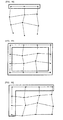
- FIGS. 1, 2 , 3 and 4 illustrate a dot pattern where codes are encoded based on a value of a distance of an interval between information dots or a distance of a prescribed direction interval held by an information dot.
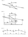
- FIG. 1 shows a dot pattern where codes are encoded based on a value of a distance of an interval between information dots.
- a starting-point information dot P0 which is to be a starting point for arranging information dots in a prescribed order is arranged. Then, an information dot P1 is arranged with a prescribed distance. An information dot P2 is arranged at a position located at a prescribed distance from the information dot P1. In the same way, an information dot P3 is arranged, and an end-point information dot P4 which is to be an end point for arranging information dots is arranged, and a dot pattern is generated.
- Encoding of codes is performed by at least any of lengths ranking permutations, lengths ranking combinations, ratio permutations, ratio combinations, or absolute values, absolute value permutations, absolute value combinations with respect to a distance L1 between the information dots P0 and P1, a distance L2 between P1 and P2, a distance L3 between P2 and P3, and a distance L4 between P3 and P4.
- the lengths ranking is to rank the distances L1 to L4 of the interval between information dots from No. (1) to No. (4). Note that, when there are two distances having the same distance of the interval between information dots, the distances having a rank from No. (1) to No. (3) will be allocated to four of the interval between information dots.
- the distances having a rank from No. (1) to No. (2) will be allocated to four of the interval between information dots.
- distances having a rank of only No. (1) will be allocated to four of the interval between information dots.
- These ranks may be ranked in ascending order or descending order.
- the allocations will be L1: No. (1), L2: No. (3), L3: No. (2) and L4: No. (4).
- any of relative distances which become to be four different ranks of No. (1) to No. (4) are allocated, and however, when candidates for further more of different distances exist in the interval between information dots, distances having any rank may be allocated, while ranked, to four of the interval between information dots.
- distances having any rank may be allocated, while ranked, to four of the interval between information dots.
- the allocations will be L1: No. (1), L2: No. (4), L3: No.
- a value of a distance of an interval between information dots may be configure so that the ranking may be determined on the premise that there is a change of the maximum of 5 to 10% relatively of the distance. Therefore, the configure of the distance where the ranking is changed by one needs a change to the extent of being surely distinguishable from a change of a distance of approximate 5 to 10%. Thereby, when a change of a distance of an interval between information dots is less than approximate 5 to 10%, they may be assumed to have the same rank.
- the ratio means a ratio of the distance L1 to L4 to a distance of a prescribed reference.
- a distance of a prescribed reference is assumed to be a distance L0 between P0 and P4
- the ratio may be assumed to be a ratio of the distance L1 to L4 to the distance L0, and may be assumed to be a ratio to any one of distances of the interval between information dots (for example, distance L1).
- FIG. 2 illustrates a dot pattern where codes are encoded based on a value of a distance of a prescribed direction interval.
- a straight line having a prescribed angle is drawn, and calculated is a distance between a straight line drawn with respect to a certain information dot and a straight line in the same direction drawn with respect to an adjacent information dot. This is a distance of a prescribed direction interval.
- a vertical line passing through each information dot is drawn.
- a distance between a straight line passing through P0 and a straight line passing through P1 is assumed to be W1
- a distance between a straight line passing through P1 and a straight line passing through P2 is assumed to be W2
- a distance between a straight line passing through P2 and a straight line passing through P3 is assumed to be W3
- a distance between a straight line passing through P3 and a straight line passing through P4 is assumed to be W4.
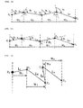
- FIGS. 3 and 4 are an example where information dots are arranged so that separate lines of the interval between information dots may intersect without information dots being arranged in a belt-like shape as illustrated in FIG. 1 . In this way, if information dots arranged in a prescribed order can only be specified, what kind of an arrangement may be applicable.
- FIG. 3 illustrates a case where codes are encoded based on the distances L1 to L4 of the interval between information dots.
- FIG. 4 illustrates a case where codes are encoded based on the distances of the prescribed direction interval W1 to W4.
- a dot pattern like this is printed on a paper surface (or displayed by a display, and this dot pattern is photographed by a camera device, and the image data are analyzed by a processor, and thereby, codes can be decoded. Then, a variety of processing corresponding to the decoded codes, for example, outputting of contents such as a voice, an image and a video, execution of a program and operation instructions such as sound reproduction and video recording etc. are carried out.
- information dots are extracted from the image data, and a value of a distance of an interval between information dots arranged adjacently or a distance of a prescribed direction interval are calculated, and decoded is codes corresponding to lengths ranking permutations, lengths ranking combinations, ratio permutations or ratio combinations, or absolute values, absolute value permutations, absolute value combinations with respect to a value of a distance of an interval between information dots etc.
- an analysis program is preferred to have been designed so that a distance of an interval between information dots are determined.
- the analysis program is preferred to have been designed so that the dot may be recognized to have been arranged at the prescribed position on the data.
- FIG. 5 illustrates an arrangement where an information dot of the next order is arranged at a position where a value of a distance of an interval between information dots is the nearest from the information dot.
- FIG. 6 illustrates an arrangement where an information dot of the next order is arranged in the prescribed direction from the information dot.
- P1 when P1 is arranged, for example, P1 is arranged in a pre-determined distance and direction (e.g., 15 degrees) from P0.
- P2 is arranged in a pre-determined distance and direction from P1.
- P3 and P4 are arranged.
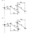
- FIGS. 7 and 8 illustrate a case where an arrangement of information dots is determined depending on a distance and direction from a certain specific information dot.
- FIG. 7 illustrates an example where an information dot is arranged in a prescribed distance and direction from the starting-point information dot P0.
- information dots P1 to P4 are arranged in pre-determined distances and directions from P0.
- FIG. 8 illustrates an example where information dots are arranged in prescribed distances and directions from the information dot P0.
- information dots are arranged in order of P1 and P2, and P3 and P4 in pre-determined distances and in the two directions from P0.
- P2 and P4 are arranged as end-point information dots.
- information dots are arranged in the plural directions more than three from P0, and end-point information dots may be arranged at end points in the plural directions.
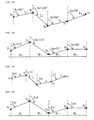
- FIGS. 9 and 10 illustrate an arrangement where an information dot of the next order is arranged at a position having a prescribed distance and prescribed rotation angle from an information dot.
- FIG. 9 illustrates an arrangement where a prescribed direction (reference line indicated by a dashed line) made to be a rotation angle reference is made to be a vertical line passing through an information dot with respect to all the information dots, and a rotation angle is determined.
- a prescribed direction reference line indicated by a dashed line
- the information dot P1 is arranged at a position that is located in a direction rotated clockwise by a prescribed angle ⁇ 1 with P0 as a center from a vertical line passing through P0, and has the prescribed distance L1 from P0.
- the information dot P2 is arranged at a position that is located in a direction rotated clockwise by a prescribed angle 2 ⁇ with P1 as a center from a vertical line passing through P1, and has the prescribed distance L2 from P1.
- information dots P3 and P4 are arranged.
- codes are encoded by at least any of lengths ranking permutations, lengths ranking combinations, ratio permutations, ratio combinations, or absolute values, absolute value permutations, absolute value combinations with respect to the distances of the interval between information dots L1, L2, L3 and L4, or the distances of a prescribed direction interval of information dots W1, W2, W3 and W4.
- FIG. 10 illustrates an arrangement where a prescribed direction (reference line indicated by a dashed line) made to be a rotation angle reference is made to be different from each other depending on an information dot.
- the information dot P1 is arranged at a position that is located in a direction rotated clockwise by a prescribed angle ⁇ 1 with P0 as a center from a vertical line passing through P0 and has the prescribed distance L1 from P0.
- the information dot P2 is arranged at a position that is located in a direction rotated clockwise by a prescribed angle ⁇ 2 with P1 as a center from the position and has the prescribed distance L2 from P1.
- the information dot P3 is arranged at a position that is located in a direction rotated clockwise by a prescribed angle ⁇ 3 with P2 as a center from a vertical line passing through P2 and has the prescribed distance L3 from P2.
- the information dot P4 is arranged at a position that is located in a direction rotated clockwise by a prescribed angle ⁇ 4 with P3 as a center from the position and has the prescribed distance L4 from P3.
- FIG. 11 illustrates a case where an information dot next to the starting-point information dot is defined as a prescribed rotation angle with respect to a prescribed direction from this starting-point information dot, and information dots subsequent to that are each defined as a prescribed rotation angle with respect to a line segment connecting the second last information dot with the last information dot.
- the information dot P1 is arranged at a position that is located in a direction rotated clockwise by a prescribed angle ⁇ 1 with P0 as a center from a vertical line passing through P0 and has the prescribed distance L1 from P0.
- the information dot P2 is arranged at a position that is located in a direction rotated by a prescribed angle ⁇ 2 with P1 as a center from a straight line passing through P0 and P1 and has the prescribed distance L1 from P1.
- the information dot P3 is arranged at a position that is located in a direction rotated by a prescribed angle ⁇ 3 with P2 as a center from a straight line passing through P1 and P2 and has the prescribed distance L3 from P2.
- the information dot P4 is arranged.
- codes may be encoded.
- FIGS. 12 and 13 illustrate an arrangement with respect to the starting-point information dot.
- FIG. 12 illustrates an arrangement where a size of the starting-point information dot is made to be different from other information dots. A size of the starting-point information dot has been larger than other information dots.
- FIG. 13 illustrates an arrangement where a shape of the starting-point information dot is made to be different.
- a shape of the starting-point information dot is configured as a triangle, and other information dots are configured as a circle. Note that a shape of a dot is not limited to an example of FIG. 13 , and it is needless to say that any shape may be applicable as long as the starting-point information dot and other information dots are identifiable.
- the starting-point information dot may be configured so as to be different from other information dots in colors, an arrangement position or optical characteristics in addition to a size and shape. In addition, it may be made for the starting-point information dot and other information dots to be identifiable by combining these.
- FIG. 14 illustrates a case where the order of information dots is made able to be specified by making a shape of information dots different from each other.
- a shape and size of each information dot are made to be different from each other. That is, P0 is made to be a big circle, P1 is made to be a small circle, P2 is made to be a big triangle, P3 is made to be a small triangle and P4 is made to be a quadrangle.
- P0 is made to be a big circle
- P1 is made to be a small circle
- P2 is made to be a big triangle
- P3 is made to be a small triangle
- P4 is made to be a quadrangle.
- specification of the order may be colors, an arrangement position, and optical characteristics of the information dot in addition to a size and shape of an information dot, and may be combinations of these.
- the arrangement position mentioned above means that an arrangement is carried out based on conditions such as the starting-point information dot is arranged at the end part of a specific direction.
- the arrangement order of information dots may be retrieved.
- FIGS. 15 and 16 illustrate a case where codes are encoded based on distances other than a distance of an interval between information dots arranged adjacently.
- FIG. 15 illustrates an arrangement where a value of a distance from the starting-point information dot P0 to each information dot, or a distance of a prescribed direction interval held by an information dot is assumed to be an index.
- a distance of an interval between information dots P0 and P1 is assumed to be L1
- a distance between P0 and P2 is assumed to be L2
- a distance between P0 and P3 is assumed to be L3
- a distance between P0 and P4 is assumed to be L4
- codes are encoded by at least any of lengths ranking permutations, lengths ranking combinations, ratio permutations, ratio combinations, or absolute values, absolute value permutations, absolute value combinations with respect to L1 to L4.
- a distance of a prescribed direction interval of P0 and P1 is assumed to be W1
- a distance of a prescribed direction interval of P0 and P2 is assumed to be W2
- a distance of a prescribed direction interval of P0 and P3 is assumed to be W3
- a distance of a prescribed direction interval of P0 and P4 is assumed to be W4
- codes are encoded by at least any of lengths ranking permutations, lengths ranking combinations, ratio permutations, ratio combinations, or absolute values, absolute value permutations, absolute value combinations with respect to W1 to W4.
- FIG. 16 illustrates an arrangement where a value of a distance from the information dot P0 to each information dot, or a distance of a prescribed direction interval held by an information dot is assumed to be an index.
- a distance of an interval between information dots is assumed to be an index
- a distance between information dots of P0 and P1 is assumed to be L1
- a distance between P0 and P2 is assumed to be L2
- a distance between P0 and P3 is assumed to be L3
- a distance between P0 and P4 is assumed to be L4
- codes are encoded by at least any of lengths ranking permutations, lengths ranking combinations, ratio permutations, ratio combinations, or absolute values, absolute value permutations, absolute value combinations with respect to L1 to L4.
- a distance in a horizontal direction between information dots of P0 and P1 is assumed to be W1
- a distance in a horizontal direction between information dots of P0 and P2 is assumed to be W2
- a distance in a horizontal direction between information dots of P0 and P3 is assumed to be W3
- a distance in a horizontal direction between information dots P0 and P4 is assumed to be W4
- codes are encoded by at least any of lengths ranking permutations, lengths ranking combinations, ratio permutations, ratio combinations, or absolute values, absolute value permutations, absolute value combinations with respect to W1 to W4.
- FIGS. 17 to 20 illustrate a case where a distance of an interval between information dots is constant.
- FIG. 17 illustrates an arrangement where an angle between mutual straight lines connecting adjacent information dots is assumed to be an index.
- a rotation angle between the vertical line passing through P0 and the straight line connecting P0 with P1 (straight line between P0 and PI) is assumed to be ⁇ 1.
- a rotation angle between the straight line with the straight line between P0 and P1 extended rightward and the straight line between P1 and P2 is assumed to be ⁇ 2.
- a rotation angle between the straight line with the straight line between P1 and P2 extended rightward and the straight line between P2 and P3 is assumed to be ⁇ 3.
- a rotation angle between the straight line with the straight line between P2 and P3 extended rightward and the straight line between P3 and P4 is assumed to be ⁇ 4.
- Codes are encoded by at least any of size ranking permutations, size ranking combinations, ratio permutations, ratio combinations, or absolute values, absolute value permutations, absolute value combinations with respect to each rotation angle ⁇ 1, ⁇ 2, ⁇ 3 and ⁇ 4.
- FIG. 18 illustrates an arrangement where codes are encoded on the basis of a rotation angle from a prescribed direction (reference line indicated by a dashed line) made to be a rotation angle reference passing through each information dot.
- a straight line having an optional inclination passing through the information dot P0 is provided, and a rotation angle made by the straight line and the straight line between P0 and P1 is assumed to be ⁇ 1.
- a straight line having an optional inclination passing through the information dot P1 is provided, and a rotation angle made by the straight line and the straight line between P1 and P2 is assumed to be ⁇ 2.
- a straight line having an optional inclination passing through the information dot P2 is provided, and a rotation angle made by the straight line and the straight line between P2 and P3 is assumed to be ⁇ 3.
- a straight line having an optional inclination passing through the information dot P3 is provided, and a rotation angle made by the straight line and the straight line between P3 and P4 is assumed to be ⁇ 4.
- Codes are encoded by at least any of size ranking permutations, size ranking combinations, ratio permutations, ratio combinations, or absolute values, absolute value permutations, absolute value combinations with respect to each rotation angle ⁇ 1, ⁇ 2, ⁇ 3 and ⁇ 4.
- FIG. 19 illustrates an arrangement where codes are encoded on the basis of a rotation angle where a prescribed direction (reference line indicated by a dashed line) made to be a rotation angle reference passing through each information dot is made to be a vertical line.
- a prescribed direction reference line indicated by a dashed line
- a vertical line passing through the information dot P0 is provided, and a rotation angle made by the vertical line and the straight line between P0 and P1 is assumed to be ⁇ 1.
- a vertical line passing through the information dot P1 is provided, and a rotation angle made by the vertical line and the straight line between P1 and P2 is assumed to be ⁇ 2.
- a vertical line passing through the information dot P2 is provided, and a rotation angle made by the vertical line and the straight line between P2 and P3 is assumed to be ⁇ 3.
- a vertical line passing through the information dot P3 is provided virtually, and a rotation angle made by the vertical line and the straight line between P3 and P4 is assumed to be ⁇ 4.
- Codes are encoded by at least any of size ranking permutations, size ranking combinations, ratio permutations, ratio combinations, or absolute values, absolute value permutations, absolute value combinations with respect to each rotation angle ⁇ 1, ⁇ 2, ⁇ 3 and ⁇ 4.
- FIG. 20 illustrates an arrangement where codes are encoded on the basis of a rotation angle made by a vertical line passing through the starting-point information dot and a straight line connecting the starting-point information dot and each of the other information dots.
- a vertical line passing through the starting-point information dot P0 is provided.
- a rotation angle made by the vertical line and the straight line between P0 and P1 is assumed to be ⁇ 1.
- a rotation angle made by the vertical line and the straight line between P0 and P2 is assumed to be ⁇ 2
- a rotation angle made by the vertical line and the straight line between P0 and P3 is assumed to be ⁇ 3
- a rotation angle made by the vertical line and the straight line between P0 and P4 is assumed to be ⁇ 4.
- Codes are encoded by at least any of size ranking permutations, size ranking combinations, ratio permutations, ratio combinations, or absolute values, absolute value permutations, absolute value combinations with respect to each rotation angle ⁇ 1, ⁇ 2, ⁇ 3 and ⁇ 4.
- FIGS. 21 to 24 illustrate a case where the distance of a prescribed direction interval held by an information dot is made to be constant.
- codes have been encoded by making different a distance of an interval between information dots or the distance of a prescribed direction interval.
- a distance in the prescribed direction held by an information dot is assumed to be constant and W1, and a rotation angle is made to be different, and thereby, codes are encoded.
- FIG. 21 illustrates an arrangement where a rotation angle made by mutual straight lines connecting adjacent information dots is assumed to be an index.
- a rotation angle between the vertical line passing through P0 and the straight line (straight line between P0 and PI) connecting P0 and P1 is assumed to be ⁇ 1.
- a rotation angle between the straight line with the straight line between P0 and P1 extended rightward and the straight line between P1 and P2 is assumed to be ⁇ 2.
- a rotation angle between the straight line with the straight line between P1 and P2 extended rightward and the straight line between P2 and P3 is assumed to be ⁇ 3.
- a rotation angle between the straight line with the straight line between P2 and P3 extended rightward and the straight line between P3 and P4 is assumed to be ⁇ 4.
- Codes are encoded by at least any of size ranking permutations, size ranking combinations, ratio permutations, ratio combinations, or absolute values, absolute value permutations, absolute value combinations with respect to each rotation angle ⁇ 1, ⁇ 2, ⁇ 3 and ⁇ 4.
- FIG. 22 illustrates an arrangement where codes are encoded on the basis of a rotation angle from a prescribed direction (reference line indicated by a dashed line) made to be a rotation angle reference passing through each information dot.
- a straight line having an optional inclination passing through the information dot P0 is provided, and a rotation angle made by the straight line and the straight line between P0 and P1 is assumed to be ⁇ 1.
- a straight line having an optional inclination passing through the information dot P1 is provided, and a rotation angle made by the straight line and the straight line between P1 and P2 is assumed to be ⁇ 2.
- a straight line having an optional inclination passing through the information dot P2 is provided, and a rotation angle made by the straight line and the straight line between P2 and P3 is assumed to be ⁇ 3.
- a straight line having an optional inclination passing through the information dot P3 is provided, and a rotation angle made by the straight line and the straight line between P3 and P4 is assumed to be ⁇ 4.
- an inclination of the straight line passing through each information dot is different for every information dot.
- Codes are encoded by at least any of size ranking permutations, size ranking combinations, ratio permutations, ratio combinations, or absolute values, absolute value permutations, absolute value combinations with respect to each rotation angle ⁇ 1, ⁇ 2, ⁇ 3 and ⁇ 4.
- FIG. 23 illustrates an arrangement where codes are encoded on the basis of a rotation angle where a prescribed direction (reference line indicated by a dashed line) made to be a rotation angle reference passing through each information dot is made to be a vertical line.
- a prescribed direction reference line indicated by a dashed line
- a vertical line passing through the information dot P0 is provided, and a rotation angle made by the vertical line and the straight line between P0 and P1 is assumed to be ⁇ 1.
- a vertical line passing through the information dot P1 is provided, and a rotation angle made by the vertical line and the straight line between P1 and P2 is assumed to be ⁇ 2.
- a vertical line passing through the information dot P2 is provided, and a rotation angle made by the vertical line and the straight line between P2 and P3 is assumed to be ⁇ 3.
- a vertical line passing through the information dot P3 is provided, and a rotation angle made by the vertical line and the straight line between P3 and P4 is assumed to be ⁇ 4.
- Codes are encoded by at least any of size ranking permutations, size ranking combinations, ratio permutations, ratio combinations, or absolute values, absolute value permutations, absolute value combinations with respect to each rotation angle ⁇ 1, ⁇ 2, ⁇ 3 and ⁇ 4.
- FIG. 24 illustrates an arrangement where a prescribed direction (reference line indicated by a dashed line) made to be a rotation angle reference passing through the starting-point information dot is made to be a vertical line, and codes are encoded on the basis of a rotation angle made by the vertical line and a straight line connecting the starting-point information dot and each of the other information dots.
- a prescribed direction reference line indicated by a dashed line
- codes are encoded on the basis of a rotation angle made by the vertical line and a straight line connecting the starting-point information dot and each of the other information dots.
- a vertical line passing through the starting-point information dot P0 is provided.
- a rotation angle made by the vertical line and the straight line between P0 and P1 is assumed to be ⁇ 1.
- a rotation angle made by the vertical line and the straight line between P0 and P2 is assumed to be ⁇ 2
- a rotation angle made by the vertical line and the straight line between P0 and P3 is assumed to be ⁇ 3
- a rotation angle made by the vertical line and the straight line between P0 and P4 is assumed to be ⁇ 4.
- Codes are encoded by at least any of size ranking permutations, size ranking combinations, ratio permutations, ratio combinations, or absolute values, absolute value permutations, absolute value combinations with respect to each rotation angle ⁇ 1, ⁇ 2, ⁇ 3 and ⁇ 4.
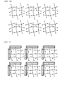
- FIGS. 25 and 26 illustrate specifically a method to encode codes based on a distance.
- FIG. 25 illustrates a case where codes are encoded based on numerical values.
- codes encoded in the dot pattern When codes are encoded by a sequence of numerical values, in a case where codes are encoded based on distance values between dots, codes encoded in the dot pattern will be 6759. When codes are encoded based on a distance in a prescribed direction between dots, codes encoded in the dot pattern will be 6458.
- codes are encoded in the same way as the decimal system.
- encoding is carried out by permutations or combinations using four among them.
- an actual distance value may be allocated.
- a numerical value to be allocated an actual distance value may be allocated.
- reading is carried out in many cases in a state where the optical reader is inclined. In that case, the actual distance value will have been changed. Therefore, it is preferable that not an actual distance, but a numerical value represented by a value existing in a prescribed range is allocated.
- FIG. 26 illustrates a case where codes are encoded based on permutations and combinations of lengths ranking of distance values.
- encoding is carried out based on permutations and combinations of No. 1 rank to No. 4 rank, No. 1 rank to No. 3 rank, No. 1 rank to No. 2 rank and all the same ranks.
- FIGS. 27 to 30 illustrate specific examples where encoding is carried out in the order of distances.
- a code 75 is allocated.
- FIG. 31 is a table illustrating such code allocations.
- code allocations indicated in FIG. 31 is an example, and it is optional what kind of code value is allocated to a case of combinations.
- FIGS. 32 to 35 illustrate a method where codes are encoded based on a rotation angle.
- codes are encoded by at least any of size ranking permutations, size ranking combinations, ratio permutations, ratio combinations, or absolute values, absolute value permutations, absolute value combinations with respect to a value of a rotation angle.
- FIG. 32 illustrates a case where codes are encoded based on a numerical value of a rotation angle in a dot pattern where a distance of an interval between information dots is constant.
- FIG. 33 illustrates a case where codes are encoded based on a numerical value of a rotation angle in a dot pattern where a distance of a prescribed direction interval of information dots is constant
- a value of an actual rotation angle may be allocated.
- a numerical value represented by a value existing in a prescribed range is allocated.
- FIG. 34 illustrates a case where codes are encoded based on size ranking permutations and combinations of a value of a rotation angle in a dot pattern where a distance of an interval between information dots is constant.
- encoding is carried out based on permutations and combinations of No. 1 rank to No. 4 rank, No. 1 rank to No. 3 rank, No. 1 rank to No. 2 rank and all the same ranks.
- FIG. 35 illustrates a case where codes are encoded based on size ranking permutations and combinations of a value of a rotation angle in a dot pattern where a distance in a horizontal direction between information dots is constant.
- encoding is carried out based on permutations and combinations of No. 1 rank to No. 4 rank, No. 1 rank to No. 3 rank, No. 1 rank to No. 2 rank and all the same ranks.
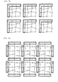
- FIG. 36 illustrates an arrangement where two or more of the dot patterns mentioned above are arranged in a belt-like shape, and one code has been encoded.
- dot pattern of the present invention it is also possible that two or more of dot patterns are arranged in vertical and horizontal directions, and one code is encoded based on a set of two or more dot patterns.
- a dot pattern of the present embodiment is a dot pattern made up of two or more rows and two or more columns.
- FIG. 37 illustrates the dot pattern of the present invention.
- the dot pattern is provided with two or more information dots arranged in two or more rows and two or more columns.
- This dot pattern is one in which codes are encoded, and an arrangement of the information dots is determined so that each dot pattern in which a different code is encoded may have a distance of an interval between information dots arranged adjacently.
- codes are encoded by at least any of lengths ranking permutations, lengths ranking combinations, ratio permutations or ratio combinations, or absolute values, absolute value permutations, absolute value combinations with respect to a distance value of an interval between information dots arranged adjacently.
- codes are encoded based only on at least any of lengths ranking permutations, lengths ranking combinations, ratio permutations, ratio combinations, or absolute values, absolute value permutations, absolute value combinations with respect to a distance value of an interval between information dots arranged adjacently.
- a belt-like dot pattern is arranged in two dimensions, and the number of codes which can be defined by each belt-like dot pattern, are combined, and thereby, the number of codes of each row and each column which can be encoded can be increased greatly.
- the present invention has superiority in the point that information is encoded based only on relative evaluation of a distance between mutually adjacent dots without depending on encoding information based on whether to arrange a dot in an arrangement direction or prescribed position from a prescribed position (virtual point) as is a conventional way, and has contributed to solution of problems such as:
- the dot patterns are usually connected in a prescribed interval in a vertical or horizontal direction.
- the dot pattern is printed on a paper surface (or, displayed by a display measure), and this dot pattern is photographed by a camera device, and the image data are analyzed by a processor, and thereby, codes can be decoded.
- Analyzing of the image data extracts an information dot from the image data, and calculates a value of a distance of an interval between information dots arranged adjacently, and decodes codes corresponding to lengths ranking permutations, lengths ranking combinations, ratio permutations, ratio combinations, or absolute values, absolute value permutations, absolute value combinations with respect to a value of a distance of an interval between information dots.
- FIG. 38 illustrates a case where in the dot pattern of FIG. 37 , codes are encoded based on a distance of a prescribed direction interval held by information dots.
- each row and each column calculate a distance of a prescribed direction interval in a prescribed direction which each starting-point information dot has. Since the way of calculating a distance of a prescribed direction interval is the same as one which has been described in the first embodiment, descriptions are omitted, here.
- a dot pattern illustrated in FIG. 39 is a dot pattern where the dot pattern described in the first embodiment is arranged in two or more rows and two or more columns, and while information dots arranged adjacently are shared in each row and each column, both of the row and column are constituted. By sharing information dots of the row and column, the number of information dots can be reduced. Thereby, while a dot density is made to be small, an information amount can be made to increase furthermore. Note that, although not illustrated, a dot pattern where some information dots constitute either a row or a column may be applicable.
- FIG. 40 illustrates a dot pattern where codes are encoded based on a distance of a prescribed direction interval held by information dots.
- Each row and each column calculates a distance of a prescribed direction interval in a prescribed direction which each starting-point information dot has. Since the way of calculating a distance of a prescribed direction interval is the same as one which has been described in the first embodiment, descriptions are omitted, here.
- FIG. 41 illustrates a dot pattern where starting-point information dots arranged in an upper end row and a left end column (or end-point information dot) have become reference dots arranged in a prescribed interval on a virtual reference line orthogonal to a row or a column. Note that the reference dot may be arranged even in a lower end row and right end column. That is, starting-point information dots (or end-point information dots) of either row of the upper or lower end part and either column of the left or right end part may be made to be the row and column where reference dots are arranged.
- starting-point information dots or end-point information dots of either row of the upper or lower end part and either column of the left or right end part may be made to be the row and column where reference dots are arranged.
- starting-point information dots and end-point information dots of rows of the upper and lower ends and columns of the right and left ends may be made to be the rows and columns where reference dots are arranged.
- starting-point information dots and end-point information dots of the columns of the right and left ends may be made to be the columns where reference dots are arranged.
- starting-point information dots (or end-point information dots) of the left end column or right end column may be made to be the column where reference dots are arranged. Note that, without all parts of either column or row where starting-point information dots (or end-point information dots) are arranged being made to be reference dots, only a part may be made to be reference dots although not illustrated.
- the reference dot if arranged so as to be able to specify a direction of the dot pattern, may be arranged in any arrangement, and may have any number. Note that it is preferable that at least one or more reference dots for representing dot patterns are arranged. When one reference dot is provided, it is necessary that a straight line (direction) including the reference dot is defined. This straight line (direction) may be calculated based on a direction of the dot pattern.
- FIGS. 45 to 50 illustrate a dot pattern where a dot pattern is arranged in two or more rows and two or more columns, and both rows and columns are constituted while information dots arranged adjacently are shared in each row and each column, and reference dots are arranged in the end part.
- FIG. 45 illustrates a dot pattern where starting-point information dots and end-point information dots arranged in rows of the upper and lower ends and columns of the right and left ends have become reference dots arranged in a prescribed interval on a virtual reference line orthogonal to rows or columns.
- FIG. 46 illustrates a dot pattern where starting-point information dots (or end-point information dots) arranged in the row of the upper end and the column of the left end have become reference dots arranged in a prescribed interval on a virtual reference line orthogonal to rows or columns.
- the reference dot may be arranged even in a lower end row and right end column. That is, either row of the upper or lower end part and either column of the left or right end part may be made to be the row and column where reference dots are arranged.
- codes are encoded based on a value of a distance of an interval between information dots arranged adjacently in a row direction and column direction.
- FIG. 46 illustrates a dot pattern where starting-point information dots (or end-point information dots) arranged in the row of the upper end and the column of the left end have become reference dots arranged in a prescribed interval on a virtual reference line orthogonal to rows or columns.
- the reference dot may be arranged even in a lower end row and right end column. That is, either row
- starting-point information dots and end-point information dots of rows of the upper and lower ends may be made to be rows where reference dots are arranged.
- starting-point information dots (or end-point information dots) of the upper end row may be made to be the row where reference dots are arranged.
- FIG. 49 illustrates a dot pattern where in the dot pattern of FIG. 45 , reference dots are further arranged at a position where virtual reference lines orthogonal to rows or columns intersect.
- FIG. 50 illustrates a dot pattern where in the dot pattern of FIG. 46 , a reference dot is further arranged at a position where virtual reference lines orthogonal to rows or columns intersect.
- FIGS. 51 to 54 illustrate definition of a direction of a dot pattern.
- FIG. 51 is a modification example of the dot pattern of FIG. 42 , and illustrates a dot pattern where with respect to the center between reference dots of both ends arranged on a virtual reference line (dashed dotted line), the direction of the dot pattern has been defined while the prescribed interval is determined so that reference dots on this virtual reference line (dashed dotted line) may be laterally asymmetrical.
- FIG. 52 is a modification example of the dot pattern of FIG. 41 , and illustrates a dot pattern where with respect to the center between reference dots of both ends arranged on a virtual reference line (dashed dotted line), the direction of the dot pattern has been defined while the prescribed interval is determined so that reference dots on this virtual reference line (dashed dotted line) may be laterally asymmetrical.
- reference dots are arranged only in the one side, and however, when two or more of the dot patterns are arranged in a prescribed interval, reference dots come to be arranged vertically and laterally, and if reference dots are vertically and laterally symmetrical in appearance, it becomes difficult to recognize the direction of the dot pattern. Therefore, by making the arrangement vertically (or laterally) asymmetrical, the direction of the dot pattern has been enabled to be discriminated.
- FIG. 53 illustrates an example in which the arrangement of reference dots of the dot pattern of FIG. 49 has been changed and illustrates a dot pattern where with respect to a dashed dotted line intersecting at a right angle at the center between reference dots of both ends arranged on the virtual reference line in a vertical direction, the direction of the dot pattern has been defined while the prescribed interval is determined so that reference dots on this virtual reference line may be vertically asymmetrical.
- reference dots are vertically and laterally symmetrical, it becomes difficult to recognize the direction of the dot pattern. Therefore, by making the arrangement vertically (or laterally) asymmetrical, the direction of the dot pattern is made to be able to be discriminated.
- FIG. 54 illustrates an example in which the arrangement of reference dots of the dot pattern of FIG. 50 has been changed and illustrates a dot pattern where with respect to the center between reference dots of both ends arranged on a virtual reference line (dashed dotted line), the direction of the dot pattern has been defined while the prescribed interval is determined so that reference dots on this virtual reference line (dashed dotted line) may be laterally asymmetrical.
- reference dots are arranged only in the one side, and however, when two or more of the dot patterns are arranged in a prescribed interval, reference dots come to be arranged vertically and laterally, and if reference dots are vertically and laterally symmetrical in appearance, it becomes difficult to recognize the direction of the dot pattern. Therefore, by making the arrangement laterally (or vertically) asymmetrical, the direction of the dot pattern is made to be able to be discriminated.
- FIG. 55 illustrates an example in which the arrangement of reference dots of the dot pattern of FIG. 42 has been changed and illustrates a dot pattern where a reference dot arranged on the virtual reference line is arranged while shifted in a prescribed direction, and the direction of the dot pattern has been defined.
- the direction of the dot pattern can be defined.
- FIG. 55 since reference dots arranged on the top in the right and left side are shifted in a right direction, the direction of the dot pattern can be recognized. Note that, when the reference dot is arranged while shifted in a right direction, it is a design matter whether a direction of the dot pattern is made to be vertical or lateral.
- FIG. 56 illustrates an example in which the arrangement of a reference dot of the dot pattern of FIG. 41 has been changed and illustrates a dot pattern where a reference dot arranged on the virtual reference line is arranged while shifted in a prescribed direction, and the direction of the dot pattern has been defined.
- reference dots are arranged only in the one side, and however, when two or more of the dot patterns are arranged in a prescribed interval, reference dots come to be arranged vertically and laterally, and if reference dots are vertically and laterally symmetrical in appearance, it becomes difficult to recognize the direction of the dot pattern. Then, by the shift of the reference dot, the direction of the dot pattern can be defined.
- FIG. 57 illustrates an example in which the arrangement of a reference dot of the dot pattern of FIG. 49 has been changed and illustrates a dot pattern where reference dots arranged on the virtual reference line are arranged while shifted in a prescribed direction, and the direction of the dot pattern has been defined.
- the direction of the dot pattern can be defined.
- the direction of the dot pattern can be recognized. Note that, when reference dots are arranged while shifted in an upper direction, it is a design matter whether a direction of the dot pattern is made to be vertical or lateral.
- FIG. 58 illustrates an example in which the arrangement of a reference dot of the dot pattern of FIG. 50 has been changed and illustrates a dot pattern where a reference dot arranged on the virtual reference line is arranged while shifted in a prescribed direction, and the direction of the dot pattern has been defined.
- reference dots are arranged only in the one side, and however, when two or more of the dot patterns are arranged in a prescribed interval, reference dots come to be arranged vertically and laterally, and if reference dots are vertically and laterally symmetrical in appearance, it becomes difficult to recognize the direction of the dot pattern. Then, by the shift of the reference dot, the direction of the dot pattern can be defined. In FIG. 58 , since a reference dot arranged at the third position from the top in the left end is shifted in a right direction, it can be recognized that the dot pattern is facing right. Note that, when the reference dot is arranged while shifted in a right direction, it is a design matter whether a direction of the dot pattern is made to be vertical or lateral.
- FIG. 59 illustrates a dot pattern where starting-point information dots and end-point information dots arranged in rows of the upper and lower ends and columns of the right and left ends have become reference dots arranged in a prescribed shape in the direction orthogonal to the row or column. Note that, as for information dots except the reference dots, codes are encoded based on a value of a distance of interval between information dots arranged adjacently in a row direction and column direction, and the direction of the dot pattern is defined by an arrangement shape of the reference dots.
- the direction of the dot pattern is preferred to be defined by the prescribed shape being expressed by an arrangement of all or a part of reference dots.
- this shape may be any type of shape if designed as a pattern in advance, when the shape shows non-axial symmetry which does not correspond to the shape before rotation even if rotated by 180 degrees with both ends of the reference dot as a center, the direction of the dot pattern can be defined from the shape itself.
- preferable is an arrangement such that an arrangement shape of the reference dot can be distinguished from the arrangement shape having a belt-like shape of the information dot.
- FIG. 60 illustrates a dot pattern where starting-point information dots and end-point information dots arranged in the upper end row and left end column have become reference dots arranged in prescribed shape in a direction orthogonal to the row or column.
- the reference dot may be arranged even in a lower end row and right end column. That is, either row of the upper or lower end part and either column of the left or right end part may be made to be the row and column where reference dots are arranged.
- codes are encoded based on a value of a distance of an interval between information dots arranged adjacently in a row direction and column direction, and the direction of the dot pattern is defined by the arrangement shape of the reference dots.
- reference dots are arranged only in the one side, and however, when two or more of the dot patterns are arranged in a prescribed interval, reference dots come to be arranged vertically and laterally, and if reference dots are vertically and laterally symmetrical in appearance, it becomes difficult to recognize the direction of the dot pattern.
- the direction of the dot pattern is preferred to be defined by the prescribed shape being expressed by an arrangement of all or a part of reference dots.
- this shape may be any type of shape if designed as a pattern in advance, when the shape shows non-axial symmetry which does not correspond to the shape before rotation even if rotated by 180 degrees with both ends of the reference dot as a center, the direction of the dot pattern can be defined from the shape itself.
- preferable is an arrangement such that an arrangement shape of the reference dot can be distinguished from the arrangement shape having a belt-like shape of the information dot.
- FIG. 61 illustrates a dot pattern where in the dot pattern of FIG. 59 , reference dots are arranged in a shared position outside the position arranged in the prescribed shape in the direction orthogonal to the row or column.
- FIGS. 62 and 63 illustrate a dot pattern where in the dot pattern of FIG. 62 , reference dots are arranged in a shared position outside the position arranged in the prescribed shape in the direction orthogonal to the row or column.
- FIG. 63 illustrates a case where codes are encoded based on a distance of a prescribed direction interval held by information dots.
- each row and each column used for encoding of codes, although each row and each column calculate a distance of a prescribed direction interval in a prescribed direction which each starting-point information dot has, the prescribed direction in a row direction and a column direction is each constant in FIG. 63 .
- FIGS. 64 to 67 illustrate a way of defining a prescribed direction which the starting-point information dot has.
- a prescribed direction which an information dot arranged adjacently in the row direction has is assumed to be a vertical direction
- a prescribed direction which an information dot arranged adjacently in the column direction has is assumed to be a horizontal direction. Then, with respect to the row direction, a distance between vertical lines of the adjacent information dots is calculated. With respect to the column direction, a distance between horizontal lines of the adjacent information dots is calculated.
- the vertical line and horizontal line are easy to be configured, and analyzed by a processor. Therefore, with respect to information dots arranged adjacently in the row direction, the vertical direction is assumed to be the prescribed direction, and with respect to information dots arranged adjacently in the column direction, the horizontal direction is assumed to be the prescribed direction, and thereby, it becomes possible for the processor to calculate easily the distance of a prescribed direction interval.
- the dot pattern illustrated in FIG. 64 is the dot pattern illustrated in FIG. 37 .
- the dot pattern illustrated in FIG. 65 is the dot pattern illustrated in FIG. 39 .
- the dot pattern illustrated in FIG. 66 is the dot pattern illustrated in FIG. 49 .
- the dot pattern illustrated in FIG. 67 is the dot pattern illustrated in FIG. 50 .
- FIGS. 68 and 69 illustrate a way of defining of a prescribed direction which the information dot has.
- the prescribed direction held by information dots arranged adjacently in a row direction or in a column direction is assumed to be a direction of a line segment connecting two reference dots.
- the dot pattern illustrated in FIG. 68 is the dot pattern illustrated in FIG. 61 , and is constituted by four rows x four columns.
- the prescribed direction held by information dots arranged adjacently in the second row direction is provided in a direction orthogonal to a line segment connecting the first and second reference dots from the top in each of the right end and the left end.
- the prescribed direction held by information dots arranged adjacently in the third row direction is provided in a direction orthogonal to a line segment connecting the second and third reference dots from the top in each of the right end and the left end.
- the prescribed direction held by information dots arranged adjacently in the second column direction is provided in a direction orthogonal to a line segment connecting the first and second reference dots from the left in each of the upper end and the lower end.
- the prescribed direction held by information dots arranged adjacently in the third column direction is provided in a direction orthogonal to a line segment connecting the second and third reference dots from the left in each of the upper end and the lower end.
- the dot pattern illustrated in FIG. 69 is the dot pattern illustrated in FIG. 62 , and is constituted by four rows x four columns.
- the prescribed direction held by information dots arranged adjacently in the row direction is provided in a direction orthogonal to a line segment connecting the first and third reference dots from the top in the left end.
- the prescribed direction held by information dots arranged adjacently in the column direction is provided in a direction orthogonal to a line segment connecting the first and third reference dots from the left in the upper end.
- the reference dots to be connected may not be adjacent reference dots mutually.
- information may be defined also for the reference dot. That is, numerical values are defined also for at least any of lengths ranking permutations, lengths ranking combinations, ratio permutations, ratio combinations, or absolute values, absolute value permutations, absolute value combinations with respect to a distance between reference dots arranged adjacently or a distance value of a prescribed direction interval.
- the reference dots of the left end have a permutation of (8), (10) and (12) from the top with respect to distance values.
- the permutation is made not to be used for permutations of distances between other dots, and thereby, it is possible to define the direction and boundary of the dot pattern based on the reference dots of the left end.
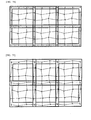
- Dot patterns illustrated in FIGS. 37 , 41 and 58 described above are usually connected in a prescribed interval in a vertical or lateral direction as illustrated FIGS. 70, 71 and 72 .
- dot patterns illustrated in FIGS. 55 , 53 and 61 that are dot patterns having reference dots in both ends
- reference dots arranged in both ends of two or more of rows and/or columns as illustrated in FIGS. 73 , 74 and 75 are arranged in the same shape mutually, and reference dots arranged in the same shape mutually are coupled laterally and vertically while overlapped.
- reference dots arranged in both ends of two or more of the rows and/or columns are arranged in the same shape mutually as illustrated in FIG. 76 , and two or more reference dots arranged in the same shape mutually are coupled in a lateral or vertical direction while overlapped, and connecting and arranging may be made to be carried out in a prescribed interval in the other direction.
- the target dot pattern is constituted by four rows x four columns, and while reference dots of the second row among vertical reference dots arranged at equal intervals in the left and right columns are made to be shifted in an upper direction, the direction of the dot pattern is determined. Horizontal reference dots arranged in the upper and lower rows are arranged at equal intervals.
- Reference dots of the second and third column are made to be connected vertically, and the connected lines are assumed to be a first and second virtual vertical lines, and reference dots of the second column before shifted in the left and right columns and reference dots of the third column are made to be connected laterally, and the connected lines are assumed to be a first and second virtual horizontal lines.
- 13 ways of codes can be encoded by one row or column
- a distance increment in a different prescribed direction is configured in an ascending order from the shortest distance while having differences no less than 10%.
- a camera inclination (30 to 40 degrees) at the time of dot pattern reading, this has been configured so that ranking of a distance of an interval between information dots may be determined accurately on the premise that an error of a value of a distance of an interval between information dots is approximately 5%.
- the distance is determined to be the same distance, and can be recognized to be at the same rank.
- the error mentioned above changes depending on a camera resolution or lens performance, and therefore, it is necessary to configure the allowances after sufficient operation tests based on operating conditions have been carried out.
- reference dots of the second row are made to be shifted in an upper direction by 2.
- (8, 12, 10) from the top is obtained, and one which has a sequence having the same values as distances in a prescribed direction of an information dot does not exist, and it can be specified that this column (8, 12, 10) is the vertical reference dots.
- codes of the same amount as permutations and combinations of distances in a prescribed direction between other three information dots can be configured.
- 13 5 371,293 ways of codes can be defined by all the rows, columns and horizontal reference dots.
- FIG. 77 (b) illustrates an example where information dots are arranged actually.
- a distance between reference dots has been assumed to be 10, any numerical value may be applicable, and a shift of the reference dot and an arrangement of information dots may be configured by the same ratio on the basis of numerical values between reference dots.
- a printing accuracy may be 600 DPI
- a distance between reference dots may be 10 pixels.
- a size of a dot may be 1 pixel or 2x2 pixels. Although 1 pixel is acceptable considering a visual effect in a case of dot printing, when there are large dispersions in printing, a recognition rate can be avoided from being reduced while a size of a dot is made to be 2x2 pixels.
- FIGS. 78 and 79 illustrate the number of code allocations which can be expressed by the present invention.
- the reference dots in the left end have a permutation of (8), (10), (12) from the top with respect to a distance value. This permutation is not made to be used for permutations with respect to distances between other dots, and thereby, a direction and boundary of the dot pattern can be defined by the reference dots in the left end.
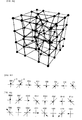
- the dot pattern made up of two or more rows and two or more columns has been described as the dot pattern of the second embodiment, it is possible that a three-dimensional dot pattern having a three-dimensional arrangement is generated while two or more dots are arranged also in a depth direction in addition to the row direction and column direction as illustrated in FIG. 80 .
- 32 reference dots are arranged along eight edges of a cube, and 32 information dots are arranged inside.
- dots arranged in a depth direction information can be encoded based on a value of a distance of an interval between information dots arranged adjacently in a depth direction, and in addition to this, it is possible to carry out encoding by the same method as the method already described in the second embodiment.
- dots which can be recognized physically by a prescribed method such as recognizing electrically or optically, and magnetically are arranged in the inside of a solid substance (with contents packed) or a substance with a plane member stacked.
- dots may be stored with elements integrated.
- coordinate values (XYZ value) of dots constituting a three-dimensional dot pattern are stored as digital information, and decoding thereof can be carried out. These are excellent in security since code information is not converted directly into a numerical value.
- the first embodiment (dot pattern constituted by one row (or column)), the second embodiment (dot pattern constituted by two or more rows and two or more columns), the third embodiment (dot pattern constituted by two or more rows, two or more columns, and two or more depths) have been each described, and however, the categories of these embodiments are not ones that categorize Claims claimed by Applicant in the present application.
- an implementation of the dot pattern of the second embodiment may include a total implementation of the first embodiment
- an implementation of the dot pattern of the third embodiment may include a total implementation of the first and second embodiments.
- a dot pattern described in the present invention is generated by a program as image data on a computer, and is printed out onto printing media such as paper, and thereby, is formed on a printing surface.
- a method to form a dot pattern on a product not only a method using a printer, but all known output devices may be used.
- a dot pattern may be displayed on a display device.
- encoded codes can be decoded by using a reading device.
- a reading device of a dot pattern is at least provided with an imaging device for imaging a dot pattern, a processing device, and a storage device.
- the reading device means both of a case where the imaging device, the processing device and the storage device are provided in one casing, and a case where the imaging device, the processing device and the storage device are provided in two or more casings.
- the imaging device includes one which has employed a method to carry out reading with the reading device contacted to a medium where a dot pattern is printed, and one which has employed a method to carry out reading with the reading device in a state apart from a medium.
- various scanners etc. are all included in addition to so-called an electronic pencil or one which is a pen type referred to as a voice pen, one which is provided with an imaging device on a bottom face of a figure, and one which carries out reading while a medium where a dot pattern is printed is placed on a card reader.
- a mobile phone In one which has employed a method to carry out reading with the reading device in a state apart from a medium, a mobile phone, a smart phone, one which carries out imaging using a camera built in a tablet type device, and one which carries out imaging using a usual camera are all included.
- a program to be executed by a processing device is stored, and in this program, processing to detect a dot pattern from image data imaged by the imaging device and processing to decode codes encoded by a dot pattern are included.
- Decoding of codes is carried out based on the described encoding algorithm of a dot pattern.
- the decoded code can be used for the corresponding processing. With respect to what kind of processing is performed, usage may be possible for all kinds of processing.
- information corresponding to codes may be read and outputted from the storage device.
- Information corresponding to codes may be searched for from Internet.
- a medium where a dot pattern has been formed can be use for a mouse pad, a tablet, a touch panel and a map etc.
- FIG. 78 is an example where a dot pattern has been arranged actually in the example illustrated in FIG. 77 mentioned above, and FIG. 79 illustrates the number of code allocations which can be expressed by the present invention.
- the reference dots of the left column have a permutation of (8), (10) and (12) from the top with respect to a distance value. This permutation is made not to be used for permutations of distances between other dots, and thereby, can be distinguished from others, and it is possible to define a direction and boundary of the dot pattern based on the reference dots of the left column.
- a dot pattern constituted by four rows x four columns
- a dot pattern can be arranged by the same generation method.
- a dot pattern constituted by, e.g. five rows xfive column when 7x7 virtual points where dots are arranged are configured at nine places, permutations and combinations of distance lengths in a prescribed direction between all information dots are configured uniquely in the same way as FIG. 77 , and codes can be encoded.
- ⁇ 1.5 / ⁇ - 0.5 may be applicable. Note that this threshold value ⁇ is used in a case of decoding of codes.
- a distance numerical value configured at the time of generating the dot pattern is assumed to be D
- errors due to a dot arrangement deformation, a deviation in printing and a distortion of a printing medium of photographed images in a state where a camera is inclined are also taken into consideration, and as for the threshold value in that case, ⁇ , and ⁇ 2 are configured as an absolute value, and D can be specified from ⁇ 1 ⁇ D ⁇ 2 .
- this method is used and may be used in searching for the reference dot having a distance between reference dots which is different from the distance in a prescribed direction of an interval between information dots.
- the read numerical values of a prescribed distance of an interval between information dots and the ranking of the distances can also be used while combined.
- regions indicated by a dashed line in FIGS. 83 and 84 are the maximum region where information dots at the time of reading the dot pattern are located, and have corresponded to the region where a deviation in printing, a distortion of a printing medium, and a dot arrangement deformation due to a camera inclination (30 to 40 degrees) at the time of dot pattern reading are taken into consideration.
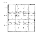
- a generation method of a dot pattern where codes are encoded based on a distance of an interval between information dots will be described using FIG. 85 .
- the target dot pattern has reference dots arranged in rows and columns of both ends, and is constituted by four rows x four columns, and reference dots of the first row and fourth row among vertical reference dots arranged at equal intervals in the left and right columns are shifted in an upper direction, and a direction of the dot pattern has been determined.
- Horizontal reference dots arranged in the upper and lower rows are arranged at equal intervals. Note that, it is needless to say that this way of determining the direction of dot pattern is equivalent to that reference dots of the first column and fourth column among the vertical reference dots arranged at equal intervals in the upper and lower rows are shifted in an upper direction, and a direction of the dot pattern is determined.
- reference dots in the column direction is assumed to have a distance between reference dots which has a different distance from a distance in a prescribed direction of an interval between information dots.
- reference dots in the left column have a permutation of distance values (12) (10) and (8) from the top. This permutation is not made to be used in other permutations of a distance of an interval between information dots, and thereby, the direction and boundary of the dot pattern can be defined by an arrangement of reference dots arranged on a straight line in the left column. Note that, in the present example, although an interval between reference dots which adjoin information dots is an equal interval, when an arrangement of reference dots can be specified as a pattern, any arrangement may be applicable.
- each of four information dots (P 11 , P 12 . P 21 and P 22 ) adjoins two reference dots, and is arranged while an interval of an interval between information dots for encoding is formed. Therefore, centering on eight reference dots which form an interval between information dots, a circle is drawn with an initial value of this interval distance as a radius, and the information dot may be arranged at an intersection point of circles drawn from two reference points mentioned above.
- a dot pattern where codes are encoded can be generated, and however, an arrangement of the dot pattern may be generated by any method.
- arrangements of information dots to reproduce distances of information dots of all the combinations are calculated by computation in advance and stored it in a table, and the dot pattern may be generated while the table is referred to at the time of generation.
- dot patterns can be arranged by the same generation method even when the row and column are increased.
- a dot pattern constituted by five rows x five columns for example, there are nine information dots except reference dots, and four information dots arranged at the corner among the nine adjoin two reference dots, and configure an initial value of the distance of the interval between information dots in the same way as FIG. 85 .
- an information dot located between information dots each in two corners in a row or column direction calculated is an intersection point of circles drawn while distance configured by an initial value from one adjacent reference dot and either of information dots in two corners made to be a radius.
- an intersection point with an information dot in the other corner is calculated, and an intermediate value of the two intersection points is arranged as an information dot located between information dots of two corners.
- positions of information dots located near the center are calculated in the same way. Subsequently, the position of the information dot is shifted and corrected until conditions are matched, and arrangements of nine information dots are configured, and encoding is carried out by permutations and combinations of lengths of distances of all intervals between information dots.
- the present reading method is completely the same as the method to read a dot pattern described in (1) to (7) of ⁇ Method to read dot pattern generated based on distance in prescribed direction of an interval between information dots, and decoding of code>, and a description of "distance in a prescribed direction of an interval between information dots" may be read as a "distance of an interval between information dots”.
- a region illustrated with a dashed line in FIG. 86 is the maximum region where information dots are located when read by a camera, and have corresponded to the region where a deviation in printing, a distortion of a printing medium, and a dot arrangement deformation due to a camera inclination (30 to 40 degrees) at the time of dot pattern reading are taken into consideration.
- a typical method in that case is the method where a coordinate transformation matrix is calculated on the basis of deformation situation of arrangements of reference dots, which have been specified by (1) to (5) of ⁇ Method to read dot pattern generated based on distance in prescribed direction of an interval between information dots, and decoding of code>, and the matrix is multiplied by coordinate values of all the dots, and the arrangement before deformation is recovered.
- a coordinate transformation matrix is calculated from a change (gradation) of brightness of an image which is imaged, and the arrangement before deformation is recovered.
- processing to read the dot pattern, and to calculate and decode the ranking of the distance in a prescribed direction of the interval between information dots or the lengths of the distance in a prescribed direction of the interval between information dots is carried out by a program and/or a circuit which are built-in in an optical reading device (camera).
- FIGS. 88 to 91 illustrate an example of a structure of an optical reading device, and any one irradiates a medium surface with infrared light from an IR LED, and reflected light from the medium surface is converged by Lens through IR Filter, and is imaged on a CMOS sensor. Note that, imaging through a pinhole without using Lens is also possible by irradiating with a considerably strong infrared light.
- FIGS. 88 and 89 by irradiating the medium surface with infrared light emitted from IR LED through Diffuser, irradiation to the medium surface with uniform infrared light has been realized.
- light with which irradiation is carried out may not be infrared light, but may be light with other frequencies. It is important that light is applied and dots can be recognized by receiving the reflected light, and for that purpose, any configuration may be acceptable. For example, as light with which irradiation is carried out, natural light or visible light is used, and dots may be recognized by image processing etc.
- Codes decoded by the optical reading device are transmitted through a radio or a cable from the optical reading device to electronic apparatuses such as various PCs, a mobile phone, a smart phone, a TV, a STB, an audio apparatus, a game machine and an IP, and corresponding processing is performed.
- electronic apparatuses such as various PCs, a mobile phone, a smart phone, a TV, a STB, an audio apparatus, a game machine and an IP, and corresponding processing is performed.
- information corresponding to decoded codes may be transmitted.
- the optical reading device performs only imaging of the dot pattern, and transmits imaged dot pattern images to the above-mentioned electronic apparatus etc., and decoding may be carried out by the electronic apparatuses.
- information corresponding to decoded codes may read from a storage medium provided in the inside or the outside, and may be outputted.
- Information corresponding to the above-mentioned codes may not be data, but may be an address, file name and processing instructions, in which information are stored. These codes and information are transmitted to a server (cloud) via the Internet, and corresponding information are transmitted from the server to the above-mentioned electronic apparatuses and optical reading device, and corresponding processing can be carried out furthermore.
- the present invention can record a lot of information with few dot densities, and can be widely used for a security system, forgery prevention, purchase and distribution of music and video with accounting accompanied and catalog shopping since the recorded information is not able to be decoded easily by a third party from coordinate values where dots have been arranged.
- industrial applicability of the present invention is not limited to the above, and there is applicability in all kinds of aspects such as a conventional education system, a toy and a game etc.
Landscapes
- Engineering & Computer Science (AREA)
- Theoretical Computer Science (AREA)
- Physics & Mathematics (AREA)
- General Physics & Mathematics (AREA)
- Databases & Information Systems (AREA)
- Data Mining & Analysis (AREA)
- General Engineering & Computer Science (AREA)
- Electromagnetism (AREA)
- Health & Medical Sciences (AREA)
- General Health & Medical Sciences (AREA)
- Toxicology (AREA)
- Artificial Intelligence (AREA)
- Computer Vision & Pattern Recognition (AREA)
- Image Processing (AREA)
- Editing Of Facsimile Originals (AREA)
- Compression Or Coding Systems Of Tv Signals (AREA)
Applications Claiming Priority (3)
| Application Number | Priority Date | Filing Date | Title |
|---|---|---|---|
| JP2012219902 | 2012-10-01 | ||
| JP2012244923A JP5344328B1 (ja) | 2012-10-01 | 2012-11-06 | ドットパターン、ドットパターン形成媒体、ドットパターンの画像データを生成するプログラム、ドットパターン形成装置、光学装置、光学読み取り装置、情報入出力装置、ドットパターン読み取り装置 |
| PCT/JP2013/076722 WO2014054647A1 (fr) | 2012-10-01 | 2013-10-01 | Motifs de points, support de formation de motifs de points, programme pour la génération de données d'image pour motifs de points, appareil de formation de motifs de points, dispositif optique, lecteur de dispositif optique, dispositif d'entrée/sortie d'information, lecteur de motifs de points |
Publications (2)
| Publication Number | Publication Date |
|---|---|
| EP2905727A1 true EP2905727A1 (fr) | 2015-08-12 |
| EP2905727A4 EP2905727A4 (fr) | 2016-06-29 |
Family
ID=49764843
Family Applications (1)
| Application Number | Title | Priority Date | Filing Date |
|---|---|---|---|
| EP13843900.5A Withdrawn EP2905727A4 (fr) | 2012-10-01 | 2013-10-01 | Motifs de points, support de formation de motifs de points, programme pour la génération de données d'image pour motifs de points, appareil de formation de motifs de points, dispositif optique, lecteur de dispositif optique, dispositif d'entrée/sortie d'information, lecteur de motifs de points |
Country Status (7)
| Country | Link |
|---|---|
| US (1) | US20150262051A1 (fr) |
| EP (1) | EP2905727A4 (fr) |
| JP (7) | JP5344328B1 (fr) |
| KR (1) | KR20150063421A (fr) |
| CN (1) | CN105122275B (fr) |
| PH (1) | PH12015500941A1 (fr) |
| WO (1) | WO2014054647A1 (fr) |
Cited By (1)
| Publication number | Priority date | Publication date | Assignee | Title |
|---|---|---|---|---|
| CN106529634A (zh) * | 2015-09-10 | 2017-03-22 | 原相科技股份有限公司 | 利用图样进行编码与解码的方法及其系统 |
Families Citing this family (11)
| Publication number | Priority date | Publication date | Assignee | Title |
|---|---|---|---|---|
| CN103945125A (zh) * | 2014-04-14 | 2014-07-23 | 立德高科(北京)数码科技有限责任公司 | 能够对点阵图形图像进行分析的摄像装置及其方法 |
| EP3045214A1 (fr) | 2015-01-14 | 2016-07-20 | Cartamundi Turnhout N.V. | Jeu de plateau avec reconnaissance de motif |
| WO2016173738A1 (fr) * | 2015-04-30 | 2016-11-03 | Nestec S.A. | Code et récipient de système pour préparer une boisson ou un aliment |
| TWI545504B (zh) * | 2015-08-31 | 2016-08-11 | 原相科技股份有限公司 | 利用圖樣進行解碼的方法及其系統 |
| US9600700B1 (en) | 2015-08-31 | 2017-03-21 | Pixart Imaging Inc. | Portable electronic device and operation method thereof |
| US9805239B2 (en) | 2015-08-31 | 2017-10-31 | Pixart Imagine Inc. | QR code detecting device and operation method thereof |
| CN111587445A (zh) | 2017-07-20 | 2020-08-25 | 拉瓦艾迪私人有限公司 | 安全标签 |
| CN108334922B (zh) * | 2018-03-13 | 2020-01-21 | 深圳闳宸科技有限公司 | 点阵二维码及点阵二维码的编码和识别方法 |
| DE102018115146A1 (de) * | 2018-06-24 | 2019-12-24 | Industry365 Ug (Haftungsbeschränkt) | Verfahren zur Herstellung für das menschliche Auge nicht sichtbarer und nicht kopierbarer Sicherheitselemente in einer Abbildung sowie Verfahren zum Authentizitätsnachweis von Produkten auf Basis des Abgleichs von ungleichen Informationen sowie gedruckte Abbildung |
| CN113297872B (zh) * | 2021-03-24 | 2024-01-12 | 福州符号信息科技有限公司 | 一种Dotcode识别方法、设备 |
| CN113313781A (zh) * | 2021-06-15 | 2021-08-27 | 福建正孚软件有限公司 | 一种基于二维纹路的文件防伪方法和系统 |
Family Cites Families (19)
| Publication number | Priority date | Publication date | Assignee | Title |
|---|---|---|---|---|
| US4404764A (en) * | 1981-08-07 | 1983-09-20 | Handy C. Priester | Message medium having corresponding optical and tactile messages |
| JPH08241363A (ja) * | 1995-03-03 | 1996-09-17 | Olympus Optical Co Ltd | コード読み取り装置及び記録媒体 |
| JPH10243127A (ja) * | 1997-02-25 | 1998-09-11 | Canon Inc | 画像処理装置及び方法 |
| JP3980983B2 (ja) * | 2002-10-02 | 2007-09-26 | 沖電気工業株式会社 | 透かし情報埋め込み方法,透かし情報検出方法,透かし情報埋め込み装置,及び,透かし情報検出装置 |
| US7475824B2 (en) | 2003-03-17 | 2009-01-13 | Kenji Yoshida | Information input/output method using dot pattern |
| US7318195B2 (en) * | 2003-08-08 | 2008-01-08 | Sean Donahue | System and method for integrating tactile language with the visual alphanumeric characters |
| JP3766678B2 (ja) * | 2003-12-25 | 2006-04-12 | 健治 吉田 | ドットパターンを用いた情報入出力方法 |
| CN1598873B (zh) * | 2004-08-17 | 2010-04-28 | 顾泽苍 | 可在纸上大量记录数据的网屏编码控制方法 |
| CN101044026A (zh) * | 2004-10-15 | 2007-09-26 | 吉田健治 | 印刷形成点图形的媒体面的印刷结构、印刷方法及读取方法 |
| JP3771252B1 (ja) * | 2005-07-01 | 2006-04-26 | 健治 吉田 | ドットパターン |
| US20090091530A1 (en) * | 2006-03-10 | 2009-04-09 | Kenji Yoshida | System for input to information processing device |
| DE102008017168A1 (de) * | 2008-04-02 | 2009-10-08 | Crossmedia Solution Gmbh & Co. Kg | Verfahren zum Speichern und Auslesen von Daten |
| CN102099817B (zh) * | 2008-08-12 | 2014-08-13 | 株式会社新克 | 信息显示系统及用于该系统的点图案印刷片 |
| RU2568308C2 (ru) * | 2009-07-13 | 2015-11-20 | Кенджи Йошида | Потоковое точечное изображение, способ формирования потокового точечного изображения, способ ввода/вывода информации с использованием потокового точечного изображения и точечное изображение |
| JP2011053753A (ja) * | 2009-08-31 | 2011-03-17 | B-Core Inc | 光学式自動認識コード及びその読み取り方法 |
| JP5277403B2 (ja) * | 2010-01-06 | 2013-08-28 | 健治 吉田 | 情報入力用の曲面体、情報入力用の地図、情報入力用の図面 |
| JP4625139B1 (ja) * | 2010-06-03 | 2011-02-02 | 傳生 西▲崎▼ | 情報表現方法、情報表現パターンが形成された物品、情報出力装置、及び、情報表現装置 |
| JP2012244923A (ja) * | 2011-05-26 | 2012-12-13 | Iseki & Co Ltd | 栽培施設 |
| WO2013027234A1 (fr) * | 2011-08-22 | 2013-02-28 | Zak株式会社 | Code bidimensionnel de type point de satellite et procédé de lecture associé |
-
2012
- 2012-11-06 JP JP2012244923A patent/JP5344328B1/ja not_active Expired - Fee Related
-
2013
- 2013-06-18 JP JP2013127191A patent/JP5581541B2/ja not_active Expired - Fee Related
- 2013-10-01 JP JP2014539763A patent/JP6533895B2/ja active Active
- 2013-10-01 KR KR1020157009122A patent/KR20150063421A/ko not_active Application Discontinuation
- 2013-10-01 CN CN201380051656.XA patent/CN105122275B/zh not_active Expired - Fee Related
- 2013-10-01 WO PCT/JP2013/076722 patent/WO2014054647A1/fr active Application Filing
- 2013-10-01 US US14/432,936 patent/US20150262051A1/en not_active Abandoned
- 2013-10-01 EP EP13843900.5A patent/EP2905727A4/fr not_active Withdrawn
-
2014
- 2014-06-26 JP JP2014131510A patent/JP6450907B2/ja active Active
-
2015
- 2015-04-28 PH PH12015500941A patent/PH12015500941A1/en unknown
-
2017
- 2017-09-19 JP JP2017179514A patent/JP6397977B2/ja not_active Expired - Fee Related
-
2018
- 2018-06-11 JP JP2018111480A patent/JP6623465B2/ja active Active
-
2019
- 2019-11-06 JP JP2019201264A patent/JP2020024747A/ja active Pending
Cited By (2)
| Publication number | Priority date | Publication date | Assignee | Title |
|---|---|---|---|---|
| CN106529634A (zh) * | 2015-09-10 | 2017-03-22 | 原相科技股份有限公司 | 利用图样进行编码与解码的方法及其系统 |
| CN106529634B (zh) * | 2015-09-10 | 2019-10-01 | 原相科技股份有限公司 | 利用图样进行编码与解码的方法及其系统 |
Also Published As
| Publication number | Publication date |
|---|---|
| JP2014132376A (ja) | 2014-07-17 |
| EP2905727A4 (fr) | 2016-06-29 |
| JP6623465B2 (ja) | 2019-12-25 |
| JP2014209374A (ja) | 2014-11-06 |
| WO2014054647A1 (fr) | 2014-04-10 |
| JP2018028918A (ja) | 2018-02-22 |
| JP6533895B2 (ja) | 2019-06-26 |
| JP2018137004A (ja) | 2018-08-30 |
| JP6397977B2 (ja) | 2018-09-26 |
| CN105122275B (zh) | 2019-10-15 |
| PH12015500941A1 (en) | 2015-07-06 |
| US20150262051A1 (en) | 2015-09-17 |
| JP6450907B2 (ja) | 2019-01-16 |
| KR20150063421A (ko) | 2015-06-09 |
| JPWO2014054647A1 (ja) | 2016-08-25 |
| JP5344328B1 (ja) | 2013-11-20 |
| CN105122275A (zh) | 2015-12-02 |
| JP2014089693A (ja) | 2014-05-15 |
| JP5581541B2 (ja) | 2014-09-03 |
| JP2020024747A (ja) | 2020-02-13 |
Similar Documents
| Publication | Publication Date | Title |
|---|---|---|
| EP2905727A1 (fr) | Motifs de points, support de formation de motifs de points, programme pour la génération de données d'image pour motifs de points, appareil de formation de motifs de points, dispositif optique, lecteur de dispositif optique, dispositif d'entrée/sortie d'information, lecteur de motifs de points | |
| CA2613046C (fr) | Image tramee | |
| US7422154B2 (en) | Apparatus and methods relating to image coding | |
| US8553284B2 (en) | Information input/output method using dot pattern | |
| CN106462785B (zh) | 二维码以及二维码的分析系统 | |
| US20120037695A1 (en) | Embedded media barcode links and systems and methods for generating and using them | |
| CN104781834A (zh) | 二维码、二维码的生成系统以及分析程序 | |
| WO2010099738A1 (fr) | Procédé d'incorporation et d'identification d'informations dans une image d'impression | |
| CN106462786A (zh) | 二维码、二维码的分析系统以及二维码的制作系统 | |
| TWI439943B (zh) | 點圖像編碼結構、其解碼方法與電子裝置 | |
| JP6471835B2 (ja) | 情報処理装置、制御方法、及びプログラム | |
| JP4949134B2 (ja) | カメラ位置認識システム | |
| US8019181B2 (en) | Image generation apparatus, image processing apparatus, computer readable medium and computer data signal | |
| CN109063806A (zh) | 一种长条小型二维码编码方法 | |
| US9158956B2 (en) | Reader, reading method and computer program product | |
| CN109934185A (zh) | 数据处理方法及装置、介质和计算设备 | |
| KR100860110B1 (ko) | 도트 패턴을 이용한 정보 입출력 방법 | |
| Veinidis et al. | 3D Reconstruction of Fishes Using Coded Structured Light | |
| JP2006331322A (ja) | 検索用タグ及びこれを使用した情報検索システム | |
| JP4765894B2 (ja) | 画像生成装置、情報読み取り装置および記録媒体 | |
| JP4916229B2 (ja) | プログラム、情報記憶媒体、2次元コード生成システム及び2次元コードが印刷された印刷物の製造方法 | |
| WO2001071644A1 (fr) | Appareil et procedes pour images | |
| CN114239631A (zh) | 二维码识别方法、装置、存储介质及电子设备 | |
| JP3858051B6 (ja) | ドットパターンを用いた情報入出力方法 | |
| US20050131653A1 (en) | Eye-flow guiding level calculating system, eye-flow guiding level calculating program, and eye-flow guiding level calculating method |
Legal Events
| Date | Code | Title | Description |
|---|---|---|---|
| PUAI | Public reference made under article 153(3) epc to a published international application that has entered the european phase |
Free format text: ORIGINAL CODE: 0009012 |
|
| 17P | Request for examination filed |
Effective date: 20150430 |
|
| AK | Designated contracting states |
Kind code of ref document: A1 Designated state(s): AL AT BE BG CH CY CZ DE DK EE ES FI FR GB GR HR HU IE IS IT LI LT LU LV MC MK MT NL NO PL PT RO RS SE SI SK SM TR |
|
| AX | Request for extension of the european patent |
Extension state: BA ME |
|
| DAX | Request for extension of the european patent (deleted) | ||
| RA4 | Supplementary search report drawn up and despatched (corrected) |
Effective date: 20160527 |
|
| RIC1 | Information provided on ipc code assigned before grant |
Ipc: G06K 1/12 20060101ALI20160520BHEP Ipc: G06K 19/06 20060101AFI20160520BHEP Ipc: G06K 7/10 20060101ALI20160520BHEP |
|
| STAA | Information on the status of an ep patent application or granted ep patent |
Free format text: STATUS: THE APPLICATION IS DEEMED TO BE WITHDRAWN |
|
| 18D | Application deemed to be withdrawn |
Effective date: 20170103 |