EP2905513A1 - Diaphragm damper - Google Patents
Diaphragm damper Download PDFInfo
- Publication number
- EP2905513A1 EP2905513A1 EP13843327.1A EP13843327A EP2905513A1 EP 2905513 A1 EP2905513 A1 EP 2905513A1 EP 13843327 A EP13843327 A EP 13843327A EP 2905513 A1 EP2905513 A1 EP 2905513A1
- Authority
- EP
- European Patent Office
- Prior art keywords
- rubber
- diaphragm damper
- portions
- elastic member
- metal diaphragms
- Prior art date
- Legal status (The legal status is an assumption and is not a legal conclusion. Google has not performed a legal analysis and makes no representation as to the accuracy of the status listed.)
- Granted
Links
Images




Classifications
-
- F—MECHANICAL ENGINEERING; LIGHTING; HEATING; WEAPONS; BLASTING
- F02—COMBUSTION ENGINES; HOT-GAS OR COMBUSTION-PRODUCT ENGINE PLANTS
- F02M—SUPPLYING COMBUSTION ENGINES IN GENERAL WITH COMBUSTIBLE MIXTURES OR CONSTITUENTS THEREOF
- F02M37/00—Apparatus or systems for feeding liquid fuel from storage containers to carburettors or fuel-injection apparatus; Arrangements for purifying liquid fuel specially adapted for, or arranged on, internal-combustion engines
- F02M37/0011—Constructional details; Manufacturing or assembly of elements of fuel systems; Materials therefor
- F02M37/0041—Means for damping pressure pulsations
-
- F—MECHANICAL ENGINEERING; LIGHTING; HEATING; WEAPONS; BLASTING
- F02—COMBUSTION ENGINES; HOT-GAS OR COMBUSTION-PRODUCT ENGINE PLANTS
- F02M—SUPPLYING COMBUSTION ENGINES IN GENERAL WITH COMBUSTIBLE MIXTURES OR CONSTITUENTS THEREOF
- F02M55/00—Fuel-injection apparatus characterised by their fuel conduits or their venting means; Arrangements of conduits between fuel tank and pump F02M37/00
- F02M55/04—Means for damping vibrations or pressure fluctuations in injection pump inlets or outlets
-
- F—MECHANICAL ENGINEERING; LIGHTING; HEATING; WEAPONS; BLASTING
- F02—COMBUSTION ENGINES; HOT-GAS OR COMBUSTION-PRODUCT ENGINE PLANTS
- F02M—SUPPLYING COMBUSTION ENGINES IN GENERAL WITH COMBUSTIBLE MIXTURES OR CONSTITUENTS THEREOF
- F02M59/00—Pumps specially adapted for fuel-injection and not provided for in groups F02M39/00 -F02M57/00, e.g. rotary cylinder-block type of pumps
- F02M59/44—Details, components parts, or accessories not provided for in, or of interest apart from, the apparatus of groups F02M59/02 - F02M59/42; Pumps having transducers, e.g. to measure displacement of pump rack or piston
- F02M59/447—Details, components parts, or accessories not provided for in, or of interest apart from, the apparatus of groups F02M59/02 - F02M59/42; Pumps having transducers, e.g. to measure displacement of pump rack or piston means specially adapted to limit fuel delivery or to supply excess of fuel temporarily, e.g. for starting of the engine
-
- F—MECHANICAL ENGINEERING; LIGHTING; HEATING; WEAPONS; BLASTING
- F16—ENGINEERING ELEMENTS AND UNITS; GENERAL MEASURES FOR PRODUCING AND MAINTAINING EFFECTIVE FUNCTIONING OF MACHINES OR INSTALLATIONS; THERMAL INSULATION IN GENERAL
- F16J—PISTONS; CYLINDERS; SEALINGS
- F16J3/00—Diaphragms; Bellows; Bellows pistons
- F16J3/02—Diaphragms
-
- F—MECHANICAL ENGINEERING; LIGHTING; HEATING; WEAPONS; BLASTING
- F02—COMBUSTION ENGINES; HOT-GAS OR COMBUSTION-PRODUCT ENGINE PLANTS
- F02M—SUPPLYING COMBUSTION ENGINES IN GENERAL WITH COMBUSTIBLE MIXTURES OR CONSTITUENTS THEREOF
- F02M2200/00—Details of fuel-injection apparatus, not otherwise provided for
- F02M2200/31—Fuel-injection apparatus having hydraulic pressure fluctuations damping elements
- F02M2200/315—Fuel-injection apparatus having hydraulic pressure fluctuations damping elements for damping fuel pressure fluctuations
-
- F—MECHANICAL ENGINEERING; LIGHTING; HEATING; WEAPONS; BLASTING
- F02—COMBUSTION ENGINES; HOT-GAS OR COMBUSTION-PRODUCT ENGINE PLANTS
- F02M—SUPPLYING COMBUSTION ENGINES IN GENERAL WITH COMBUSTIBLE MIXTURES OR CONSTITUENTS THEREOF
- F02M2200/00—Details of fuel-injection apparatus, not otherwise provided for
- F02M2200/90—Selection of particular materials
- F02M2200/9015—Elastomeric or plastic materials
-
- F—MECHANICAL ENGINEERING; LIGHTING; HEATING; WEAPONS; BLASTING
- F02—COMBUSTION ENGINES; HOT-GAS OR COMBUSTION-PRODUCT ENGINE PLANTS
- F02M—SUPPLYING COMBUSTION ENGINES IN GENERAL WITH COMBUSTIBLE MIXTURES OR CONSTITUENTS THEREOF
- F02M2200/00—Details of fuel-injection apparatus, not otherwise provided for
- F02M2200/90—Selection of particular materials
- F02M2200/9053—Metals
Definitions
- the present invention relates to a diaphragm damper.
- the present invention relates to a diaphragm damper which is used for reducing pulsation generated in a high-pressure pump used in an engine.
- a fuel chamber is formed in a fuel inlet side, and the fuel is pressurized and discharged by repeating "suction stroke” which sucks the fuel from the fuel chamber to a pressurizing chamber when a plunger moves down, “metering stroke” which returns a part of the fuel in the pressurizing chamber to the fuel chamber when the plunger moves up, and “pressurizing stroke” which pressurizes the fuel when the plunger further moves up after a suction valve is closed.
- the high-pressure pump mentioned above has a diaphragm damper for reducing the pulsation generated in the fuel chamber built-in.
- the high-pressure pump is variously designed to enhance an effect of reducing the pulsation in the diaphragm.
- patent document 1 discloses a device which employs an elastic member for a support member supporting a metal diaphragm constructing a diaphragm damper (patent document 1).
- parts of the high-pressure pump oscillate on the basis of an operation of a suction valve, a plunger and a discharge valve, at the driving time of the high-pressure pump.
- the oscillation is transmitted to the fuel, and is transmitted as the pulsation to a piping which is connected to the high-pressure pump, and there is a problem that an abnormal noise is generated due to resonance of the oscillation.
- the diaphragm damper is structured such as to elastically support the outer peripheral portion of the metal diaphragm by the rubber-like elastic member and the wave washer (the pressing member), a structure is complicated, and the rubber-like elastic member and the wave washer (the pressing member) has a reduced degree of freedom in shapes.
- the present invention is made by taking the problem mentioned above into consideration, and an object of the present invention is to provide a diaphragm damper which does not change the conventional metal diaphragm attaching structure, does not obstruct the space in which the fuel flows within the fuel chamber, can optionally set the amount of volume change on the basis of the resonance frequency and the pressure, and can achieve the optimization of the diaphragm damper performance.
- the diaphragm damper according to the present invention is a diaphragm damper structured such that a high-pressure gas is sealed in a high-pressure chamber formed by two discoid metal diaphragms which are bonded to each other in their outer peripheral portions, wherein a rubber-like elastic member is arranged within the high-pressure chamber.
- the present invention achieves the following effects.
- the rubber-like elastic member is arranged within the high-pressure chamber.
- the conventional metal diaphragm attaching structure is not changed, the space in which the fuel flows within the fuel chamber is not obstructed, it is possible to optionally set the amount of volume change on the basis of the resonance frequency and the pressure, and it is possible to achieve the optimization of the diaphragm damper performance.
- the rubber-like elastic member is constructed by a discoid sheet portion which is provided so as to come into contact with each of two discoid metal diaphragms, and a plurality of rubber projections which are arranged circumferentially between the sheet portions.
- the rubber projection is integrally formed with the sheet portion and is structured such as to alternately extend from the one sheet portion toward the surface of the other sheet portion.
- a leading end of the rubber projection is formed into a circular arc shape in its cross section.
- the rubber-like elastic member is arranged in a center portion of the high-pressure chamber so as to be concentric with the metal diaphragms.
- the rubber-like elastic member is in contact with both of two metal diaphragms. As a result, it is possible to more effectively damp the resonance of the metal diaphragms.
- the rubber-like elastic member is provided with a plurality of positioning leg portions which come into contact with an outer peripheral portion of the metal diaphragms.
- end portions of a plurality of positioning leg portions are integrally formed with a ring-shaped portion which comes into contact with an outer peripheral portion of the metal diaphragms.
- the rubber-like elastic member is constructed by two discoid portions which come into contact with each of two metal diaphragms in their whole surfaces, and a connection portion which connects the two discoid portions to each other in their center portions.
- the metal diaphragm is formed a repeated pattern of annular concave portions and annular convex portions which are formed into concentric circles. As a result, it is possible to more securely obtain a pulsation absorbing action of the diaphragm damper.
- a diaphragm damper according to the present invention is used in a high-pressure pump which pressurizes a fuel supplied from a fuel tank on the basis of a reciprocating movement of a plunger so as to pressure feed to an injector side.
- a fuel chamber is formed in a fuel inlet side, and the fuel is pressurized and discharged by repeating "suction stroke” which sucks the fuel from the fuel chamber to a pressurizing chamber when a plunger moves down, “metering stroke” which returns a part of the fuel in the pressurizing chamber to the fuel chamber when the plunger moves up, and “pressurizing stroke” which pressurizes the fuel when the plunger further moves up after a suction valve is closed.
- the diaphragm damper according to the present invention is used for reducing pulsation which is generated in a fuel chamber of the high-pressure pump as mentioned above.
- diaphragm damper according to the present invention is provided with the following structures as shown in Figs. 1 to 3 .
- a high-pressure gas is sealed into a high-pressure chamber 11 formed by two discoid metal diaphragms 1 and 1 which are bonded to each other in their outer peripheral portions 10.
- a rubber-like elastic member 2 is arranged within the high-pressure chamber 11.
- a material of the rubber-like elastic member 2 preferably employs a rubber-like elastic material such as a nitrile rubber (NBR), a hydrogen additive nitrile rubber (HNBR), an acrylic rubber (ACM), a silicone rubber (VMQ), a fluorosilicone rubber (FVMQ), a fluorine-contained rubber (FKM), an ethylene propylene rubber (EPDM), a chloroprene rubber (CR), a chlorosulfonated polyethylene (CSM), a styrene butadiene rubber (SBR), a butyl rubber (IIR), and an urethane rubber (AU), which has a Shore hardness of Hs 50 or less.
- a rubber-like elastic material such as a nitrile rubber (NBR), a hydrogen additive nitrile rubber (HNBR), an acrylic rubber (ACM), a silicone rubber (VMQ), a fluorosilicone rubber (FVMQ), a fluorine-contained rubber (F
- the Shore hardness Hs is set to be equal to or less because a damping function of the metal diaphragms 1 and 1 is not inhibited.
- a space in which the fuel flows within the fuel chamber is not inhibited without changing the conventional attaching structure of the metal diaphragms 1 and 1, and it is possible to optionally set an amount of volume change caused by a resonance frequency and a pressure, so that it is possible to optimize the diaphragm damper performance.
- the metal diaphragms 1 and 1 are obtained by folding outer peripheral edges of two discoid members which are flat and are constructed by metal members into a curves shape and integrally bonding the outer peripheral edges to each other, and a discoid space chamber forming a high-pressure chamber 11 is formed in an inner portion of the metal diaphragms 1 and 1.
- a welding means or a caulking means is appropriately selected and used for integrally bonding.
- the rubber-like elastic member 2 is constructed by discoid sheet portions 25 and 26 which are provided so as to respectively come into contact with two discoid metal diaphragms 1 and 1, and a plurality of projections 251 and 261 which are circumferentially arranged between the sheet portions 25 and 26.
- the rubber-projections 251 and 261 are integrally formed with the sheet portions 25 and 26 as is apparent from Fig. 2 , and are structured such as to extend from the one sheet portions 25 and 26 toward surfaces of the other sheet portions 25 and 26.
- three rubber projections 261 are arranged on the one surface of the sheet portion 26 so as to be circumferentially uniform (at intervals of 120 degree).
- three rubber projections 261 having the same shape are arranged on the one surface of the other sheet portion 25 so as to be circumferentially uniform (at intervals of 120 degree) in the same manner.
- three rubber projections 251 and 261 are respectively arranged on the one surfaces of the sheet portions 25 and 26 uniformly, that is, six rubber projections are totally provided, as shown by a broken line in Fig. 1 , however, at least two rubber projections may be respectively provided, totally four rubber projections may be provided.
- the diaphragm damper is finished by adhering a surface where the rubber projections 251 and 261 of the sheet portions 25 and 26 are not provided, to each of the inner surfaces of the metal diaphragms 1 and 1 by an adhesive agent, thereafter assembling them in such a manner that the rubber projections 251 and 261 of the sheet portions 25 and 26 are deviated from each other at 60 degree, and integrating the outer peripheral portions 10 of two discoid metal diaphragms 1 and 1 by welding.
- a space in which the fuel flows within the fuel chamber is not inhibited without changing the conventional attaching structure of the metal diaphragms 1 and 1, and it is possible to optionally set an amount of volume change caused by a resonance frequency and a pressure, so that it is possible to optimize the diaphragm damper performance.
- a plurality of rubber projections 251 and 261 are structured such as to be uniformly arranged on the circumference which is less deformed in the outer peripheral side of the metal diaphragms 1 and 1, it is possible to effectively damp the resonance of the metal diaphragms without inhibiting the deformation of the center portion which is most deformed in the metal diaphragms 1 and 1.
- the rubber projections 251 and 261 are structured such as to extend alternately from the one sheet portions 25 and 26 toward the surfaces of the other sheet portions 25 and 26, as shown in Fig. 2 , the balance of the rubber-like elastic members 2 and 2 is good, and it is possible to effectively damp the resonance of the metal diaphragms 1 and 1.
- leading ends of the rubber projections 251 and 261 are formed into a circular arc shape in their cross section.
- the rubber-like elastic member 2 is formed into a columnar shape, and is arranged in a center portion 112 of the high-pressure chamber 11 so as to be concentric with the metal diaphragms 1 and 1.
- both end portions in an axial direction of the columnar rubber-like elastic member 2 are in contact with each of two metal diaphragms 1 and 1.
- the columnar rubber-like elastic member 2 may be formed into a cylindrical shape obtained by boring a center portion of the rubber-like elastic member 2. In the case of the cylindrical shape mentioned above, the rubber-like elastic member 2 is more easily deformed. As a result, the damper function of the metal diaphragms 1 and 1 is not inhibited.
- a different point from the aspect described above exists in a point that the rubber-like elastic member 2 is provided with a plurality of positioning leg portions 21 and 21 which come into contact with the outer peripheral side 12 of the high-pressure chamber 11, and a point that the metal diaphragms 1 and 1 are formed a repeated pattern of annular concave portions 13 and 13 and annular convex portions 14 and 14 which are formed into concentric circles.
- Three positioning leg portions 21 are formed so that three positioning leg portions are uniformly arranged from the outer peripheral surface of the columnar member 21 which is positioned at the center.
- outer peripheral end portions of the positioning leg portions 21 and 21 are formed into a columnar projection shape.
- the metal diaphragms 1 and 1 are formed the repeated pattern of the annular concave portions 13 and 13 and the annular convex portions 14 and 14 which are formed into the concentric circles, it is possible to obtain a more secure pulsation absorbing action of the diaphragm damper.
- the rubber-like elastic member 2 is constructed by two discoid portions 23 and 23 which respectively come into contact with two metal diaphragms 1 and 1 with wide areas, and a connection portion 24 which connects two discoid portions 23 and 23 to each other in their center portions.
- the rubber-like elastic member 2 is stored in such a manner that whole surfaces of two discoid portions 23 and 23 are respectively in contact with two metal diaphragms 1 and 1, as shown in Fig. 12 .
- the rubber-like elastic member 2 is in contact with the metal diaphragms 1 and 1 with the wider range, it is possible t more securely damp the resonance of the metal diaphragms 1 and 1.
- the diaphragm damper according to the present invention is useful as the diaphragm damper which is used for reducing the pulsation generated in the high-pressure pump employed in the engine.
Landscapes
- Engineering & Computer Science (AREA)
- General Engineering & Computer Science (AREA)
- Mechanical Engineering (AREA)
- Chemical & Material Sciences (AREA)
- Combustion & Propulsion (AREA)
- Diaphragms And Bellows (AREA)
- Fuel-Injection Apparatus (AREA)
- Vibration Dampers (AREA)
- Springs (AREA)
Abstract
Description
- The present invention relates to a diaphragm damper.
- Further, the present invention relates to a diaphragm damper which is used for reducing pulsation generated in a high-pressure pump used in an engine.
- There has been conventionally known a high-pressure pump which pressurizes fuel supplied from a fuel tank on the basis of a reciprocating movement of a plunger so as to pressure feed to an injector side.
- In this kind of high-pressure pump, a fuel chamber is formed in a fuel inlet side, and the fuel is pressurized and discharged by repeating "suction stroke" which sucks the fuel from the fuel chamber to a pressurizing chamber when a plunger moves down, "metering stroke" which returns a part of the fuel in the pressurizing chamber to the fuel chamber when the plunger moves up, and "pressurizing stroke" which pressurizes the fuel when the plunger further moves up after a suction valve is closed.
- The high-pressure pump mentioned above has a diaphragm damper for reducing the pulsation generated in the fuel chamber built-in.
- Further, the high-pressure pump is variously designed to enhance an effect of reducing the pulsation in the diaphragm.
- For example,
patent document 1 discloses a device which employs an elastic member for a support member supporting a metal diaphragm constructing a diaphragm damper (patent document 1). - However, in the device described in the
patent document 1, since the elastic member pinches the metal diaphragm from both upper and lower side directions, a space occupied by the elastic member becomes large, thereby blocking a space in which the fuel flows within the fuel chamber. - Therefore, an amount of the fuel which can be sucked into the fuel chamber is reduced, and there is a risk that the effect of reducing the pulsation by the diaphragm can not be sufficiently obtained.
- Further, parts of the high-pressure pump oscillate on the basis of an operation of a suction valve, a plunger and a discharge valve, at the driving time of the high-pressure pump.
- The oscillation is transmitted to the fuel, and is transmitted as the pulsation to a piping which is connected to the high-pressure pump, and there is a problem that an abnormal noise is generated due to resonance of the oscillation.
- Consequently, there has been proposed a diaphragm damper which is structured such as to support an outer peripheral portion of the metal diaphragm by a rubber-like elastic member and a wave washer (a pressing member) (patent document 2).
- However, since the diaphragm damper is structured such as to elastically support the outer peripheral portion of the metal diaphragm by the rubber-like elastic member and the wave washer (the pressing member), a structure is complicated, and the rubber-like elastic member and the wave washer (the pressing member) has a reduced degree of freedom in shapes.
- As a result, it has been hard to optionally set an amount of volume change caused by the resonance frequency and the pressure, and it has been hard to achieve optimization of a diaphragm damper performance.
-
- Patent Document 1: Japanese Unexamined Patent Publication No.
2004-138071 - Patent Document 2: Japanese Unexamined Patent Publication No.
2012-132400 - The present invention is made by taking the problem mentioned above into consideration, and an object of the present invention is to provide a diaphragm damper which does not change the conventional metal diaphragm attaching structure, does not obstruct the space in which the fuel flows within the fuel chamber, can optionally set the amount of volume change on the basis of the resonance frequency and the pressure, and can achieve the optimization of the diaphragm damper performance.
- The diaphragm damper according to the present invention is a diaphragm damper structured such that a high-pressure gas is sealed in a high-pressure chamber formed by two discoid metal diaphragms which are bonded to each other in their outer peripheral portions, wherein a rubber-like elastic member is arranged within the high-pressure chamber.
- The present invention achieves the following effects.
- According to the diaphragm damper of the invention described in a first aspect, the rubber-like elastic member is arranged within the high-pressure chamber. As a result, the conventional metal diaphragm attaching structure is not changed, the space in which the fuel flows within the fuel chamber is not obstructed, it is possible to optionally set the amount of volume change on the basis of the resonance frequency and the pressure, and it is possible to achieve the optimization of the diaphragm damper performance.
- According to a diaphragm damper of the invention described in a second aspect, the rubber-like elastic member is constructed by a discoid sheet portion which is provided so as to come into contact with each of two discoid metal diaphragms, and a plurality of rubber projections which are arranged circumferentially between the sheet portions. As a result, it is possible to effectively damp the resonance of the metal diaphragms without obstructing deformation of the center portion in which the metal diaphragms are deformed most greatly.
- According to a diaphragm damper of the invention described in a third aspect, the rubber projection is integrally formed with the sheet portion and is structured such as to alternately extend from the one sheet portion toward the surface of the other sheet portion. As a result, balance of the rubber-like elastic member is good, and it is possible to effectively damp the resonance of the metal diaphragms.
- According to a diaphragm damper of the invention described in a fourth aspect, a leading end of the rubber projection is formed into a circular arc shape in its cross section. As a result, the following property is good in relation to the deformation of the metal diaphragms, and it is possible to effectively damp the resonance of the metal diaphragms.
- According to a diaphragm damper of the invention described in a fifth aspect, the rubber-like elastic member is arranged in a center portion of the high-pressure chamber so as to be concentric with the metal diaphragms. As a result, the displacement caused by the pressure of the metal diaphragm does not become uneven. Therefore, it is possible to effectively damp the resonance of the metal diaphragms.
- According to a diaphragm damper of the invention described in a sixth aspect, the rubber-like elastic member is in contact with both of two metal diaphragms. As a result, it is possible to more effectively damp the resonance of the metal diaphragms.
- According to a diaphragm damper of the invention described in a seventh aspect, the rubber-like elastic member is provided with a plurality of positioning leg portions which come into contact with an outer peripheral portion of the metal diaphragms. As a result, since it is possible to inhibit the rubber-like elastic member from moving within the high-pressure chamber, it is possible to more stably damp the resonance of the metal diaphragms.
- According to a diaphragm damper of the invention described in an eighth aspect, end portions of a plurality of positioning leg portions are integrally formed with a ring-shaped portion which comes into contact with an outer peripheral portion of the metal diaphragms. As a result, it is possible to more enhance the damping of the resonance in the metal diaphragms, and it is possible to more securely inhibit the rubber-like elastic member from moving within the high-pressure chamber. Therefore, it is possible to more stably damp the resonance of the metal diaphragms.
- According to a diaphragm damper of the invention described in a ninth aspect, the rubber-like elastic member is constructed by two discoid portions which come into contact with each of two metal diaphragms in their whole surfaces, and a connection portion which connects the two discoid portions to each other in their center portions. As a result, since the rubber-like elastic member comes into contact with the metal diaphragm in a wider range, it is possible to more securely damp the resonance of the metal diaphragms.
- According to a diaphragm damper of the invention described in a tenth aspect, the metal diaphragm is formed a repeated pattern of annular concave portions and annular convex portions which are formed into concentric circles. As a result, it is possible to more securely obtain a pulsation absorbing action of the diaphragm damper.
-
-
Fig. 1 is a plan view of a diaphragm damper according to the present invention; -
Fig. 2 is a cross sectional view along a line B-B inFig. 1 ; -
Fig. 3 is a three-dimensional perspective view of a rubber-like elastic member which is used inFig. 2 ; -
Fig. 4 is a plan view of the other diaphragm damper according to the present invention; -
Fig. 5 is a cross sectional view along a line A-A inFig. 4 ; -
Fig. 6 is a three-dimensional perspective view of a rubber-like elastic member which is used inFig. 5 ; -
Fig. 7 is a view showing a second aspect of the diaphragm damper according to the present invention in the same manner asFig. 5 ; -
Fig. 8 is a three-dimensional perspective view of a rubber-like elastic member which is used inFig. 7 ; -
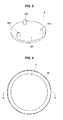
Fig. 9 is a three-dimensional perspective view of a rubber-like elastic member according to a third aspect which is used in the diaphragm damper according to the present invention; -
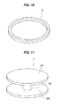
Fig. 10 is a three-dimensional perspective view of a rubber-like elastic member according to a fourth aspect which is used in the diaphragm damper according to the present invention; -
Fig. 11 is a three-dimensional perspective view of a rubber-like elastic member according to a fifth aspect which is used in the diaphragm damper according to the present invention; and -
Fig. 12 is a view showing a diaphragm damper according to the present invention which uses the rubber-like elastic member shown inFig. 11 , in the same manner asFig. 5 . - A description will be given below of the best mode for carrying out the present invention.
- A diaphragm damper according to the present invention is used in a high-pressure pump which pressurizes a fuel supplied from a fuel tank on the basis of a reciprocating movement of a plunger so as to pressure feed to an injector side.
- In this kind of high-pressure pump, a fuel chamber is formed in a fuel inlet side, and the fuel is pressurized and discharged by repeating "suction stroke" which sucks the fuel from the fuel chamber to a pressurizing chamber when a plunger moves down, "metering stroke" which returns a part of the fuel in the pressurizing chamber to the fuel chamber when the plunger moves up, and "pressurizing stroke" which pressurizes the fuel when the plunger further moves up after a suction valve is closed.
- The diaphragm damper according to the present invention is used for reducing pulsation which is generated in a fuel chamber of the high-pressure pump as mentioned above.
- Further, the diaphragm damper according to the present invention is provided with the following structures as shown in
Figs. 1 to 3 . - More specifically, a high-pressure gas is sealed into a high-
pressure chamber 11 formed by twodiscoid metal diaphragms peripheral portions 10. - Further, a rubber-like
elastic member 2 is arranged within the high-pressure chamber 11. - A material of the rubber-like
elastic member 2 preferably employs a rubber-like elastic material such as a nitrile rubber (NBR), a hydrogen additive nitrile rubber (HNBR), an acrylic rubber (ACM), a silicone rubber (VMQ), a fluorosilicone rubber (FVMQ), a fluorine-contained rubber (FKM), an ethylene propylene rubber (EPDM), a chloroprene rubber (CR), a chlorosulfonated polyethylene (CSM), a styrene butadiene rubber (SBR), a butyl rubber (IIR), and an urethane rubber (AU), which has a Shore hardness of Hs 50 or less. - The Shore hardness Hs is set to be equal to or less because a damping function of the
metal diaphragms - According to the structure mentioned above, a space in which the fuel flows within the fuel chamber is not inhibited without changing the conventional attaching structure of the
metal diaphragms - Further, the
metal diaphragms pressure chamber 11 is formed in an inner portion of themetal diaphragms - A welding means or a caulking means is appropriately selected and used for integrally bonding.
- The rubber-like
elastic member 2 is constructed bydiscoid sheet portions discoid metal diaphragms projections sheet portions - Further, the rubber-
projections sheet portions Fig. 2 , and are structured such as to extend from the onesheet portions other sheet portions - More specifically, as shown in
Fig. 3 , threerubber projections 261 are arranged on the one surface of thesheet portion 26 so as to be circumferentially uniform (at intervals of 120 degree). In the same manner, threerubber projections 261 having the same shape are arranged on the one surface of theother sheet portion 25 so as to be circumferentially uniform (at intervals of 120 degree) in the same manner. - In the present embodiment, three
rubber projections sheet portions Fig. 1 , however, at least two rubber projections may be respectively provided, totally four rubber projections may be provided. - Further, the diaphragm damper is finished by adhering a surface where the
rubber projections sheet portions metal diaphragms rubber projections sheet portions peripheral portions 10 of twodiscoid metal diaphragms - According to the structure mentioned above, a space in which the fuel flows within the fuel chamber is not inhibited without changing the conventional attaching structure of the
metal diaphragms - Further, since a plurality of
rubber projections metal diaphragms metal diaphragms - Further, since the
rubber projections sheet portions other sheet portions Fig. 2 , the balance of the rubber-likeelastic members metal diaphragms - Further, as shown in the drawing, leading ends of the
rubber projections - As a result, a good following property to the deformation of the
metal diaphragms metal diaphragms - Next, a description will be given of the other diaphragm damper according to the present invention on the basis of
Figs. 4 to 7 . - A different point from the diaphragm damper described previously exists in a point that the rubber-like
elastic member 2 is provided in the center portion of themetal diaphragms - The rubber-like
elastic member 2 is formed into a columnar shape, and is arranged in acenter portion 112 of the high-pressure chamber 11 so as to be concentric with themetal diaphragms - Further, both end portions in an axial direction of the columnar rubber-like
elastic member 2 are in contact with each of twometal diaphragms - Further, it is effective to adhere the columnar rubber-like
elastic member 2 to the metal diaphragms for holding the rubber-likeelastic member 2 to thecenter portion 112 of the high-pressure chamber 11. - Further, the columnar rubber-like
elastic member 2 may be formed into a cylindrical shape obtained by boring a center portion of the rubber-likeelastic member 2. In the case of the cylindrical shape mentioned above, the rubber-likeelastic member 2 is more easily deformed. As a result, the damper function of themetal diaphragms - Next, a description will be given of a second aspect of the diaphragm damper according to the present invention on the basis of
Figs. 7 and8 . - A different point from the aspect described above exists in a point that the rubber-like
elastic member 2 is provided with a plurality of positioningleg portions peripheral side 12 of the high-pressure chamber 11, and a point that themetal diaphragms concave portions convex portions - Three
positioning leg portions 21 are formed so that three positioning leg portions are uniformly arranged from the outer peripheral surface of thecolumnar member 21 which is positioned at the center. - Further, outer peripheral end portions of the
positioning leg portions - According to the structure mentioned above, since it is possible to inhibit the rubber-like
elastic member 2 from moving within the high-pressure chamber 11, it is possible to more stably damp the resonance of themetal diaphragms - Further, since the
metal diaphragms concave portions convex portions - Next, a description will be given of a third aspect of the rubber-like
elastic member 2 which is used in the diaphragm damper according to the present invention on the basis ofFig. 9 . - A different point from the second aspect described previously exists in a point that end portions of a plurality of positioning
leg portions portion 22 which comes into contact with the outerperipheral side 12 of the high-pressure chamber 11. - According to the structure mentioned above, since it is possible to further enhance the damping of the resonance of the
metal diaphragms elastic member 2 from moving within the high-pressure chamber 11, it is possible to more stably damp the resonance of themetal diaphragms - Next, a description will be given of a fourth aspect of the rubber-like
elastic member 2 which is used in the diaphragm damper according to the present invention on the basis ofFig. 10 . - A different point from the third aspect described previously exists in a point that the rubber-like
elastic member 2 is constructed only by the ring-shapedportion 22 according to the third aspect. - According to the structure mentioned above, since it is possible to further hold down a capacity which the rubber-like
elastic member 2 occupies within the high-pressure chamber 11, and it is possible to inhibit the rubber-likeelastic member 2 from moving within the high-pressure chamber 11, it is possible to more stably damp the resonance of themetal diaphragms - Next, a description will be given of a fifth aspect of the rubber-like
elastic member 2 which is used in the diaphragm damper according to the present invention on the basis ofFig. 11 . - The rubber-like
elastic member 2 is constructed by twodiscoid portions metal diaphragms connection portion 24 which connects twodiscoid portions - Further, the rubber-like
elastic member 2 is stored in such a manner that whole surfaces of twodiscoid portions metal diaphragms Fig. 12 . - According to the structure mentioned above, since the rubber-like
elastic member 2 is in contact with themetal diaphragms metal diaphragms - Further, it goes without saying that the present invention is not limited to the modes for carrying out the invention mentioned above, but can employ the other various structures without deviating from the scope of the present invention.
- The diaphragm damper according to the present invention is useful as the diaphragm damper which is used for reducing the pulsation generated in the high-pressure pump employed in the engine.
-
- 1
- metal diaphragm
- 2
- rubber-like elastic member
- 10
- outer peripheral portion
- 11
- high-pressure chamber
- 12
- outer peripheral side
- 13
- annular concave portion
- 14
- annular convex portion
- 20
- columnar member
- 21
- positioning leg portion
- 22
- ring-shaped portion
- 23
- discoid portion
- 24
- connection portion
- 25, 26
- sheet member
- 112
- center portion
- 256, 261
- rubber projection
Claims (10)
- A diaphragm damper structured such that a high-pressure gas is sealed in a high-pressure chamber (11) formed by two discoid metal diaphragms (1,1) which are bonded to each other in their outer peripheral portions (10),
wherein a rubber-like elastic member (2) is arranged within said high-pressure chamber (11) - The diaphragm damper according to claim 1, wherein said rubber-like elastic member (2) is constructed by discoid sheet portions (25, 26) which are provided so as to come into contact with each of said two discoid metal diaphragms (1, 1), and a plurality of rubber projections (251, 261) which are arranged circumferentially between said sheet portions (25, 26).
- The diaphragm damper according to claim 2, wherein said rubber projections (251, 261) are integrally formed with said sheet portions (25, 26) and alternately extend from one of said sheet portions (25, 26) toward the surface of the other of said sheet portions (25, 26).
- The diaphragm damper according to claim 2 or 3, wherein leading ends of said rubber projections (251, 261) are formed into a circular arc shape in their cross sections.
- The diaphragm damper according to claim 1, wherein said rubber-like elastic member (2) is arranged in a center portion (112) of said high-pressure chamber (11) so as to be concentric with said metal diaphragms (1, 1).
- The diaphragm damper according to claim 1 or 5, wherein said rubber-like elastic member (2) is in contact with each of said two metal diaphragms (1, 1).
- The diaphragm damper according to claim 5 or 6, wherein said rubber-like elastic member (2) is provided with a plurality of positioning leg portions (21, 21) which come into contact with an outer peripheral side (12) of said high-pressure chamber (11).
- The diaphragm damper according to claim 7, wherein end portions of said plurality of positioning leg portions (21, 21) are integrated with a ring-shaped portion (22) which comes into contact with an outer peripheral portion (12) of said metal diaphragms (1, 1).
- The diaphragm damper according to claim 1 or 2, wherein said rubber-like elastic member (2) is constructed by two discoid portions (23, 23) which come into contact with each of said two metal diaphragms (1, 1) in their whole surfaces, and a connection portion (24) which connects said two discoid portions (23, 23) to each other in their center portions.
- The diaphragm damper according to any one of claims 1 to 9, wherein said metal diaphragms (1,1) are formed a repeated pattern of annular concave portions (13) and annular convex portions (14) which are formed into concentric circles.
Applications Claiming Priority (3)
| Application Number | Priority Date | Filing Date | Title |
|---|---|---|---|
| JP2012221811 | 2012-10-04 | ||
| JP2013129369A JP5979606B2 (en) | 2012-10-04 | 2013-06-20 | Diaphragm damper |
| PCT/JP2013/076930 WO2014054727A1 (en) | 2012-10-04 | 2013-10-03 | Diaphragm damper |
Publications (3)
| Publication Number | Publication Date |
|---|---|
| EP2905513A1 true EP2905513A1 (en) | 2015-08-12 |
| EP2905513A4 EP2905513A4 (en) | 2015-11-25 |
| EP2905513B1 EP2905513B1 (en) | 2017-08-16 |
Family
ID=50435047
Family Applications (1)
| Application Number | Title | Priority Date | Filing Date |
|---|---|---|---|
| EP13843327.1A Active EP2905513B1 (en) | 2012-10-04 | 2013-10-03 | Diaphragm damper |
Country Status (5)
| Country | Link |
|---|---|
| US (1) | US9394865B2 (en) |
| EP (1) | EP2905513B1 (en) |
| JP (1) | JP5979606B2 (en) |
| CN (1) | CN104704267B (en) |
| WO (1) | WO2014054727A1 (en) |
Families Citing this family (13)
| Publication number | Priority date | Publication date | Assignee | Title |
|---|---|---|---|---|
| DE102013212557A1 (en) * | 2013-06-28 | 2014-12-31 | Robert Bosch Gmbh | Damping device for damping pressure pulsations in a fluid system |
| JP5854005B2 (en) * | 2013-07-12 | 2016-02-09 | 株式会社デンソー | Pulsation damper and high-pressure pump equipped with the same |
| JP5854006B2 (en) * | 2013-07-12 | 2016-02-09 | 株式会社デンソー | Pulsation damper and high-pressure pump equipped with the same |
| JP6413017B2 (en) * | 2015-05-27 | 2018-10-24 | 株式会社不二工機 | Pulsation damper |
| DE102016209423B4 (en) * | 2016-05-31 | 2025-07-03 | Robert Bosch Gmbh | High-pressure accumulator and method for producing a high-pressure accumulator |
| WO2019102982A1 (en) * | 2017-11-24 | 2019-05-31 | イーグル工業株式会社 | Metal diaphragm damper |
| WO2019106892A1 (en) * | 2017-11-28 | 2019-06-06 | 住友理工株式会社 | Composite vibration control body and metal spring equipped composite vibration control body using same |
| CN111989479B (en) * | 2018-05-18 | 2022-07-26 | 伊格尔工业股份有限公司 | shock absorber device |
| WO2019221261A1 (en) | 2018-05-18 | 2019-11-21 | イーグル工業株式会社 | Damper unit |
| JP7074563B2 (en) | 2018-05-18 | 2022-05-24 | イーグル工業株式会社 | Damper device |
| CN112055780A (en) | 2018-05-25 | 2020-12-08 | 伊格尔工业股份有限公司 | Shock absorber device |
| JP7041956B2 (en) * | 2018-09-20 | 2022-03-25 | 株式会社不二工機 | Pulsation damper |
| CN113517158A (en) * | 2021-07-13 | 2021-10-19 | 西安交通大学 | A flexible electromagnetic repulsion coil with embedded buffer structure |
Family Cites Families (26)
| Publication number | Priority date | Publication date | Assignee | Title |
|---|---|---|---|---|
| US1809927A (en) * | 1925-09-01 | 1931-06-16 | Pirelli | Means for maintaining oil pressure in high tension electric cables |
| US3346014A (en) * | 1965-04-21 | 1967-10-10 | Jacuzzi Bros Inc | Pressure tank assembly for water pressure system |
| US3948288A (en) * | 1974-12-13 | 1976-04-06 | Gardner-Denver Company | Hydraulic accumulator |
| US4164954A (en) * | 1975-02-25 | 1979-08-21 | Allan Ballard | Fluid pressure control mechanism |
| DE2910025A1 (en) * | 1979-03-14 | 1980-09-18 | Wagner Gmbh J | PRESSURE TIP COMPENSATOR FOR PULSATING LIQUID FLOWS |
| JPS6031590U (en) * | 1983-08-08 | 1985-03-04 | 三菱電機株式会社 | pump damper device |
| JPH0615162Y2 (en) * | 1984-04-24 | 1994-04-20 | 自動車電機工業株式会社 | Diaphragm |
| JPH0640495U (en) * | 1992-11-06 | 1994-05-31 | 株式会社フカエ | Vibration prevention device |
| DE4318553C2 (en) * | 1993-06-04 | 1995-05-18 | Daimler Benz Ag | Adaptive hydropneumatic pulsation damper |
| US6513500B2 (en) * | 2001-04-02 | 2003-02-04 | Delphi Technologies, Inc. | Fuel rail damping device |
| EP1411236B1 (en) | 2002-10-19 | 2012-10-10 | Robert Bosch Gmbh | Device for damping of pressure pulsations in a fluid system, especially in a fuel system of an internal combustion engine |
| US6901914B1 (en) * | 2004-08-27 | 2005-06-07 | Delphi Technologies, Inc. | Variable stiffness fuel rail pulse damper having extended dynamic range |
| JP2007247462A (en) * | 2006-03-14 | 2007-09-27 | Toyota Motor Corp | Fuel delivery pipe |
| JP4686501B2 (en) * | 2007-05-21 | 2011-05-25 | 日立オートモティブシステムズ株式会社 | Liquid pulsation damper mechanism and high-pressure fuel supply pump having liquid pulsation damper mechanism |
| JP4530053B2 (en) * | 2008-01-22 | 2010-08-25 | 株式会社デンソー | Fuel pump |
| DE102008047303A1 (en) * | 2008-02-18 | 2009-08-20 | Continental Teves Ag & Co. Ohg | Pulsationsdämpfungskapsel |
| US7520268B1 (en) * | 2008-03-18 | 2009-04-21 | Robert Bosch Gmbh | Fuel rail damping assembly including an insert |
| RU2383785C1 (en) * | 2008-10-09 | 2010-03-10 | Александр Анатольевич Строганов | Hydro-pneumatic accumulator with compressed regenerator |
| JP2010180727A (en) * | 2009-02-03 | 2010-08-19 | Toyota Motor Corp | Delivery pipe |
| DE102010003132A1 (en) * | 2010-03-23 | 2011-09-29 | Continental Teves Ag & Co. Ohg | Pulsationsdämpfungskapsel |
| DE102010030626A1 (en) * | 2010-06-29 | 2011-12-29 | Robert Bosch Gmbh | Pulsation damper element for a fluid pump and associated fluid pump |
| DE102010062693A1 (en) * | 2010-12-09 | 2012-06-14 | Robert Bosch Gmbh | Hydro storage device |
| JP5445441B2 (en) | 2010-12-23 | 2014-03-19 | 株式会社デンソー | High pressure pump |
| JP5644615B2 (en) * | 2011-03-22 | 2014-12-24 | 株式会社デンソー | Pulsation damper and high-pressure pump equipped with the same |
| JP5569573B2 (en) | 2012-03-05 | 2014-08-13 | 株式会社デンソー | High pressure pump |
| JP5821769B2 (en) * | 2012-04-24 | 2015-11-24 | 株式会社デンソー | Damper device |
-
2013
- 2013-06-20 JP JP2013129369A patent/JP5979606B2/en active Active
- 2013-10-03 EP EP13843327.1A patent/EP2905513B1/en active Active
- 2013-10-03 WO PCT/JP2013/076930 patent/WO2014054727A1/en not_active Ceased
- 2013-10-03 US US14/433,180 patent/US9394865B2/en active Active
- 2013-10-03 CN CN201380051700.7A patent/CN104704267B/en active Active
Also Published As
| Publication number | Publication date |
|---|---|
| EP2905513B1 (en) | 2017-08-16 |
| CN104704267B (en) | 2017-03-08 |
| JP2014088870A (en) | 2014-05-15 |
| JP5979606B2 (en) | 2016-08-24 |
| CN104704267A (en) | 2015-06-10 |
| US9394865B2 (en) | 2016-07-19 |
| EP2905513A4 (en) | 2015-11-25 |
| US20150260133A1 (en) | 2015-09-17 |
| WO2014054727A1 (en) | 2014-04-10 |
Similar Documents
| Publication | Publication Date | Title |
|---|---|---|
| US9394865B2 (en) | Diaphragm damper | |
| US9970435B2 (en) | Pulsation damper | |
| JP5979092B2 (en) | Pulsation damper and high-pressure fuel pump | |
| US10883462B2 (en) | Damper device with a plurality of stacked diaphragms coupled together by a coupler having holders forming a space provided between a peripheral weld of the diaphragms and the coupler | |
| JP4919783B2 (en) | Liquid seal vibration isolator | |
| US8714530B2 (en) | Fluid-filled vibration-damping device | |
| US20190152455A1 (en) | Pressure Pulsation Reducing Device and Pulsation Damping Member of Hydraulic System | |
| JP7237952B2 (en) | damper unit | |
| US8297602B2 (en) | Vibration isolator | |
| WO2019221260A1 (en) | Damper device | |
| JP5854006B2 (en) | Pulsation damper and high-pressure pump equipped with the same | |
| CN103238006A (en) | Reduced noise decoupler | |
| JP5854005B2 (en) | Pulsation damper and high-pressure pump equipped with the same | |
| JP5284463B2 (en) | Liquid-filled vibration isolator | |
| EP3715618B1 (en) | Metal diaphragm damper | |
| JP2008309191A (en) | Vibration absorbing device | |
| JP5783431B2 (en) | Pulsation damper and high-pressure pump equipped with the same | |
| EP4034761B1 (en) | Fluid damper | |
| JPWO2019225627A1 (en) | Damper device |
Legal Events
| Date | Code | Title | Description |
|---|---|---|---|
| PUAI | Public reference made under article 153(3) epc to a published international application that has entered the european phase |
Free format text: ORIGINAL CODE: 0009012 |
|
| 17P | Request for examination filed |
Effective date: 20150410 |
|
| AK | Designated contracting states |
Kind code of ref document: A1 Designated state(s): AL AT BE BG CH CY CZ DE DK EE ES FI FR GB GR HR HU IE IS IT LI LT LU LV MC MK MT NL NO PL PT RO RS SE SI SK SM TR |
|
| AX | Request for extension of the european patent |
Extension state: BA ME |
|
| RA4 | Supplementary search report drawn up and despatched (corrected) |
Effective date: 20151026 |
|
| RIC1 | Information provided on ipc code assigned before grant |
Ipc: F16J 3/02 20060101AFI20151020BHEP Ipc: F16F 15/04 20060101ALI20151020BHEP Ipc: F02M 59/44 20060101ALI20151020BHEP Ipc: F02M 37/00 20060101ALI20151020BHEP Ipc: F02M 55/04 20060101ALI20151020BHEP |
|
| DAX | Request for extension of the european patent (deleted) | ||
| GRAP | Despatch of communication of intention to grant a patent |
Free format text: ORIGINAL CODE: EPIDOSNIGR1 |
|
| STAA | Information on the status of an ep patent application or granted ep patent |
Free format text: STATUS: GRANT OF PATENT IS INTENDED |
|
| RIC1 | Information provided on ipc code assigned before grant |
Ipc: F02M 37/00 20060101ALI20170313BHEP Ipc: F16J 3/02 20060101AFI20170313BHEP Ipc: F16F 15/04 20060101ALI20170313BHEP Ipc: F02M 59/44 20060101ALI20170313BHEP Ipc: F02M 55/04 20060101ALI20170313BHEP |
|
| INTG | Intention to grant announced |
Effective date: 20170411 |
|
| GRAS | Grant fee paid |
Free format text: ORIGINAL CODE: EPIDOSNIGR3 |
|
| GRAA | (expected) grant |
Free format text: ORIGINAL CODE: 0009210 |
|
| STAA | Information on the status of an ep patent application or granted ep patent |
Free format text: STATUS: THE PATENT HAS BEEN GRANTED |
|
| AK | Designated contracting states |
Kind code of ref document: B1 Designated state(s): AL AT BE BG CH CY CZ DE DK EE ES FI FR GB GR HR HU IE IS IT LI LT LU LV MC MK MT NL NO PL PT RO RS SE SI SK SM TR |
|
| REG | Reference to a national code |
Ref country code: GB Ref legal event code: FG4D |
|
| REG | Reference to a national code |
Ref country code: CH Ref legal event code: EP |
|
| REG | Reference to a national code |
Ref country code: IE Ref legal event code: FG4D |
|
| REG | Reference to a national code |
Ref country code: AT Ref legal event code: REF Ref document number: 919382 Country of ref document: AT Kind code of ref document: T Effective date: 20170915 |
|
| REG | Reference to a national code |
Ref country code: DE Ref legal event code: R096 Ref document number: 602013025260 Country of ref document: DE |
|
| REG | Reference to a national code |
Ref country code: NL Ref legal event code: MP Effective date: 20170816 |
|
| REG | Reference to a national code |
Ref country code: LT Ref legal event code: MG4D |
|
| REG | Reference to a national code |
Ref country code: AT Ref legal event code: MK05 Ref document number: 919382 Country of ref document: AT Kind code of ref document: T Effective date: 20170816 |
|
| PG25 | Lapsed in a contracting state [announced via postgrant information from national office to epo] |
Ref country code: AT Free format text: LAPSE BECAUSE OF FAILURE TO SUBMIT A TRANSLATION OF THE DESCRIPTION OR TO PAY THE FEE WITHIN THE PRESCRIBED TIME-LIMIT Effective date: 20170816 Ref country code: SE Free format text: LAPSE BECAUSE OF FAILURE TO SUBMIT A TRANSLATION OF THE DESCRIPTION OR TO PAY THE FEE WITHIN THE PRESCRIBED TIME-LIMIT Effective date: 20170816 Ref country code: NO Free format text: LAPSE BECAUSE OF FAILURE TO SUBMIT A TRANSLATION OF THE DESCRIPTION OR TO PAY THE FEE WITHIN THE PRESCRIBED TIME-LIMIT Effective date: 20171116 Ref country code: LT Free format text: LAPSE BECAUSE OF FAILURE TO SUBMIT A TRANSLATION OF THE DESCRIPTION OR TO PAY THE FEE WITHIN THE PRESCRIBED TIME-LIMIT Effective date: 20170816 Ref country code: FI Free format text: LAPSE BECAUSE OF FAILURE TO SUBMIT A TRANSLATION OF THE DESCRIPTION OR TO PAY THE FEE WITHIN THE PRESCRIBED TIME-LIMIT Effective date: 20170816 Ref country code: NL Free format text: LAPSE BECAUSE OF FAILURE TO SUBMIT A TRANSLATION OF THE DESCRIPTION OR TO PAY THE FEE WITHIN THE PRESCRIBED TIME-LIMIT Effective date: 20170816 |
|
| PG25 | Lapsed in a contracting state [announced via postgrant information from national office to epo] |
Ref country code: IS Free format text: LAPSE BECAUSE OF FAILURE TO SUBMIT A TRANSLATION OF THE DESCRIPTION OR TO PAY THE FEE WITHIN THE PRESCRIBED TIME-LIMIT Effective date: 20171216 Ref country code: LV Free format text: LAPSE BECAUSE OF FAILURE TO SUBMIT A TRANSLATION OF THE DESCRIPTION OR TO PAY THE FEE WITHIN THE PRESCRIBED TIME-LIMIT Effective date: 20170816 Ref country code: BG Free format text: LAPSE BECAUSE OF FAILURE TO SUBMIT A TRANSLATION OF THE DESCRIPTION OR TO PAY THE FEE WITHIN THE PRESCRIBED TIME-LIMIT Effective date: 20171116 Ref country code: RS Free format text: LAPSE BECAUSE OF FAILURE TO SUBMIT A TRANSLATION OF THE DESCRIPTION OR TO PAY THE FEE WITHIN THE PRESCRIBED TIME-LIMIT Effective date: 20170816 Ref country code: PL Free format text: LAPSE BECAUSE OF FAILURE TO SUBMIT A TRANSLATION OF THE DESCRIPTION OR TO PAY THE FEE WITHIN THE PRESCRIBED TIME-LIMIT Effective date: 20170816 Ref country code: GR Free format text: LAPSE BECAUSE OF FAILURE TO SUBMIT A TRANSLATION OF THE DESCRIPTION OR TO PAY THE FEE WITHIN THE PRESCRIBED TIME-LIMIT Effective date: 20171117 Ref country code: ES Free format text: LAPSE BECAUSE OF FAILURE TO SUBMIT A TRANSLATION OF THE DESCRIPTION OR TO PAY THE FEE WITHIN THE PRESCRIBED TIME-LIMIT Effective date: 20170816 |
|
| PG25 | Lapsed in a contracting state [announced via postgrant information from national office to epo] |
Ref country code: DK Free format text: LAPSE BECAUSE OF FAILURE TO SUBMIT A TRANSLATION OF THE DESCRIPTION OR TO PAY THE FEE WITHIN THE PRESCRIBED TIME-LIMIT Effective date: 20170816 Ref country code: RO Free format text: LAPSE BECAUSE OF FAILURE TO SUBMIT A TRANSLATION OF THE DESCRIPTION OR TO PAY THE FEE WITHIN THE PRESCRIBED TIME-LIMIT Effective date: 20170816 Ref country code: CZ Free format text: LAPSE BECAUSE OF FAILURE TO SUBMIT A TRANSLATION OF THE DESCRIPTION OR TO PAY THE FEE WITHIN THE PRESCRIBED TIME-LIMIT Effective date: 20170816 |
|
| REG | Reference to a national code |
Ref country code: DE Ref legal event code: R097 Ref document number: 602013025260 Country of ref document: DE |
|
| PG25 | Lapsed in a contracting state [announced via postgrant information from national office to epo] |
Ref country code: MC Free format text: LAPSE BECAUSE OF FAILURE TO SUBMIT A TRANSLATION OF THE DESCRIPTION OR TO PAY THE FEE WITHIN THE PRESCRIBED TIME-LIMIT Effective date: 20170816 Ref country code: SK Free format text: LAPSE BECAUSE OF FAILURE TO SUBMIT A TRANSLATION OF THE DESCRIPTION OR TO PAY THE FEE WITHIN THE PRESCRIBED TIME-LIMIT Effective date: 20170816 Ref country code: IT Free format text: LAPSE BECAUSE OF FAILURE TO SUBMIT A TRANSLATION OF THE DESCRIPTION OR TO PAY THE FEE WITHIN THE PRESCRIBED TIME-LIMIT Effective date: 20170816 Ref country code: SM Free format text: LAPSE BECAUSE OF FAILURE TO SUBMIT A TRANSLATION OF THE DESCRIPTION OR TO PAY THE FEE WITHIN THE PRESCRIBED TIME-LIMIT Effective date: 20170816 Ref country code: EE Free format text: LAPSE BECAUSE OF FAILURE TO SUBMIT A TRANSLATION OF THE DESCRIPTION OR TO PAY THE FEE WITHIN THE PRESCRIBED TIME-LIMIT Effective date: 20170816 |
|
| REG | Reference to a national code |
Ref country code: CH Ref legal event code: PL |
|
| PLBE | No opposition filed within time limit |
Free format text: ORIGINAL CODE: 0009261 |
|
| STAA | Information on the status of an ep patent application or granted ep patent |
Free format text: STATUS: NO OPPOSITION FILED WITHIN TIME LIMIT |
|
| 26N | No opposition filed |
Effective date: 20180517 |
|
| GBPC | Gb: european patent ceased through non-payment of renewal fee |
Effective date: 20171116 |
|
| REG | Reference to a national code |
Ref country code: IE Ref legal event code: MM4A |
|
| REG | Reference to a national code |
Ref country code: FR Ref legal event code: ST Effective date: 20180629 |
|
| PG25 | Lapsed in a contracting state [announced via postgrant information from national office to epo] |
Ref country code: LU Free format text: LAPSE BECAUSE OF NON-PAYMENT OF DUE FEES Effective date: 20171003 Ref country code: LI Free format text: LAPSE BECAUSE OF NON-PAYMENT OF DUE FEES Effective date: 20171031 Ref country code: CH Free format text: LAPSE BECAUSE OF NON-PAYMENT OF DUE FEES Effective date: 20171031 |
|
| REG | Reference to a national code |
Ref country code: BE Ref legal event code: MM Effective date: 20171031 |
|
| PG25 | Lapsed in a contracting state [announced via postgrant information from national office to epo] |
Ref country code: SI Free format text: LAPSE BECAUSE OF FAILURE TO SUBMIT A TRANSLATION OF THE DESCRIPTION OR TO PAY THE FEE WITHIN THE PRESCRIBED TIME-LIMIT Effective date: 20170816 Ref country code: BE Free format text: LAPSE BECAUSE OF NON-PAYMENT OF DUE FEES Effective date: 20171031 Ref country code: FR Free format text: LAPSE BECAUSE OF NON-PAYMENT OF DUE FEES Effective date: 20171031 |
|
| PG25 | Lapsed in a contracting state [announced via postgrant information from national office to epo] |
Ref country code: MT Free format text: LAPSE BECAUSE OF NON-PAYMENT OF DUE FEES Effective date: 20171003 |
|
| PG25 | Lapsed in a contracting state [announced via postgrant information from national office to epo] |
Ref country code: IE Free format text: LAPSE BECAUSE OF NON-PAYMENT OF DUE FEES Effective date: 20171003 |
|
| PG25 | Lapsed in a contracting state [announced via postgrant information from national office to epo] |
Ref country code: GB Free format text: LAPSE BECAUSE OF NON-PAYMENT OF DUE FEES Effective date: 20171116 |
|
| PG25 | Lapsed in a contracting state [announced via postgrant information from national office to epo] |
Ref country code: HU Free format text: LAPSE BECAUSE OF FAILURE TO SUBMIT A TRANSLATION OF THE DESCRIPTION OR TO PAY THE FEE WITHIN THE PRESCRIBED TIME-LIMIT; INVALID AB INITIO Effective date: 20131003 |
|
| PG25 | Lapsed in a contracting state [announced via postgrant information from national office to epo] |
Ref country code: CY Free format text: LAPSE BECAUSE OF FAILURE TO SUBMIT A TRANSLATION OF THE DESCRIPTION OR TO PAY THE FEE WITHIN THE PRESCRIBED TIME-LIMIT Effective date: 20170816 |
|
| PG25 | Lapsed in a contracting state [announced via postgrant information from national office to epo] |
Ref country code: MK Free format text: LAPSE BECAUSE OF FAILURE TO SUBMIT A TRANSLATION OF THE DESCRIPTION OR TO PAY THE FEE WITHIN THE PRESCRIBED TIME-LIMIT Effective date: 20170816 |
|
| PG25 | Lapsed in a contracting state [announced via postgrant information from national office to epo] |
Ref country code: TR Free format text: LAPSE BECAUSE OF FAILURE TO SUBMIT A TRANSLATION OF THE DESCRIPTION OR TO PAY THE FEE WITHIN THE PRESCRIBED TIME-LIMIT Effective date: 20170816 |
|
| PG25 | Lapsed in a contracting state [announced via postgrant information from national office to epo] |
Ref country code: PT Free format text: LAPSE BECAUSE OF FAILURE TO SUBMIT A TRANSLATION OF THE DESCRIPTION OR TO PAY THE FEE WITHIN THE PRESCRIBED TIME-LIMIT Effective date: 20170816 |
|
| PG25 | Lapsed in a contracting state [announced via postgrant information from national office to epo] |
Ref country code: HR Free format text: LAPSE BECAUSE OF FAILURE TO SUBMIT A TRANSLATION OF THE DESCRIPTION OR TO PAY THE FEE WITHIN THE PRESCRIBED TIME-LIMIT Effective date: 20170816 |
|
| PG25 | Lapsed in a contracting state [announced via postgrant information from national office to epo] |
Ref country code: AL Free format text: LAPSE BECAUSE OF FAILURE TO SUBMIT A TRANSLATION OF THE DESCRIPTION OR TO PAY THE FEE WITHIN THE PRESCRIBED TIME-LIMIT Effective date: 20170816 |
|
| PGFP | Annual fee paid to national office [announced via postgrant information from national office to epo] |
Ref country code: DE Payment date: 20250902 Year of fee payment: 13 |