EP2905488A1 - Retainer-equipped needle rollers - Google Patents
Retainer-equipped needle rollers Download PDFInfo
- Publication number
- EP2905488A1 EP2905488A1 EP13843778.5A EP13843778A EP2905488A1 EP 2905488 A1 EP2905488 A1 EP 2905488A1 EP 13843778 A EP13843778 A EP 13843778A EP 2905488 A1 EP2905488 A1 EP 2905488A1
- Authority
- EP
- European Patent Office
- Prior art keywords
- cage
- roller
- retaining portion
- needle
- radially outer
- Prior art date
- Legal status (The legal status is an assumption and is not a legal conclusion. Google has not performed a legal analysis and makes no representation as to the accuracy of the status listed.)
- Granted
Links
- 230000007246 mechanism Effects 0.000 claims description 10
- 230000008878 coupling Effects 0.000 claims description 3
- 238000010168 coupling process Methods 0.000 claims description 3
- 238000005859 coupling reaction Methods 0.000 claims description 3
- 238000005520 cutting process Methods 0.000 claims description 3
- 239000003921 oil Substances 0.000 description 13
- 239000010687 lubricating oil Substances 0.000 description 12
- 238000005461 lubrication Methods 0.000 description 12
- 238000000034 method Methods 0.000 description 8
- 230000008569 process Effects 0.000 description 8
- 229910000831 Steel Inorganic materials 0.000 description 5
- 239000010959 steel Substances 0.000 description 5
- 230000000694 effects Effects 0.000 description 4
- 230000005540 biological transmission Effects 0.000 description 3
- 230000014509 gene expression Effects 0.000 description 2
- 230000006872 improvement Effects 0.000 description 2
- 239000000463 material Substances 0.000 description 2
- 238000003825 pressing Methods 0.000 description 2
- 238000003466 welding Methods 0.000 description 2
- 238000005299 abrasion Methods 0.000 description 1
- 230000009471 action Effects 0.000 description 1
- 230000002411 adverse Effects 0.000 description 1
- 230000000712 assembly Effects 0.000 description 1
- 238000000429 assembly Methods 0.000 description 1
- 239000010960 cold rolled steel Substances 0.000 description 1
- 238000005553 drilling Methods 0.000 description 1
- 238000005516 engineering process Methods 0.000 description 1
- 238000010438 heat treatment Methods 0.000 description 1
- 230000001050 lubricating effect Effects 0.000 description 1
- 238000004519 manufacturing process Methods 0.000 description 1
- 238000003801 milling Methods 0.000 description 1
- 238000010791 quenching Methods 0.000 description 1
- 238000010008 shearing Methods 0.000 description 1
- 239000002344 surface layer Substances 0.000 description 1
Images


Classifications
-
- F—MECHANICAL ENGINEERING; LIGHTING; HEATING; WEAPONS; BLASTING
- F16—ENGINEERING ELEMENTS AND UNITS; GENERAL MEASURES FOR PRODUCING AND MAINTAINING EFFECTIVE FUNCTIONING OF MACHINES OR INSTALLATIONS; THERMAL INSULATION IN GENERAL
- F16C—SHAFTS; FLEXIBLE SHAFTS; ELEMENTS OR CRANKSHAFT MECHANISMS; ROTARY BODIES OTHER THAN GEARING ELEMENTS; BEARINGS
- F16C33/00—Parts of bearings; Special methods for making bearings or parts thereof
- F16C33/30—Parts of ball or roller bearings
- F16C33/46—Cages for rollers or needles
- F16C33/467—Details of individual pockets, e.g. shape or roller retaining means
- F16C33/4676—Details of individual pockets, e.g. shape or roller retaining means of the stays separating adjacent cage pockets, e.g. guide means for the bearing-surface of the rollers
-
- F—MECHANICAL ENGINEERING; LIGHTING; HEATING; WEAPONS; BLASTING
- F16—ENGINEERING ELEMENTS AND UNITS; GENERAL MEASURES FOR PRODUCING AND MAINTAINING EFFECTIVE FUNCTIONING OF MACHINES OR INSTALLATIONS; THERMAL INSULATION IN GENERAL
- F16C—SHAFTS; FLEXIBLE SHAFTS; ELEMENTS OR CRANKSHAFT MECHANISMS; ROTARY BODIES OTHER THAN GEARING ELEMENTS; BEARINGS
- F16C33/00—Parts of bearings; Special methods for making bearings or parts thereof
- F16C33/30—Parts of ball or roller bearings
- F16C33/46—Cages for rollers or needles
- F16C33/54—Cages for rollers or needles made from wire, strips, or sheet metal
- F16C33/541—Details of individual pockets, e.g. shape or roller retaining means
-
- F—MECHANICAL ENGINEERING; LIGHTING; HEATING; WEAPONS; BLASTING
- F16—ENGINEERING ELEMENTS AND UNITS; GENERAL MEASURES FOR PRODUCING AND MAINTAINING EFFECTIVE FUNCTIONING OF MACHINES OR INSTALLATIONS; THERMAL INSULATION IN GENERAL
- F16C—SHAFTS; FLEXIBLE SHAFTS; ELEMENTS OR CRANKSHAFT MECHANISMS; ROTARY BODIES OTHER THAN GEARING ELEMENTS; BEARINGS
- F16C33/00—Parts of bearings; Special methods for making bearings or parts thereof
- F16C33/30—Parts of ball or roller bearings
- F16C33/46—Cages for rollers or needles
- F16C33/54—Cages for rollers or needles made from wire, strips, or sheet metal
- F16C33/542—Cages for rollers or needles made from wire, strips, or sheet metal made from sheet metal
- F16C33/543—Cages for rollers or needles made from wire, strips, or sheet metal made from sheet metal from a single part
- F16C33/545—Cages for rollers or needles made from wire, strips, or sheet metal made from sheet metal from a single part rolled from a band
-
- F—MECHANICAL ENGINEERING; LIGHTING; HEATING; WEAPONS; BLASTING
- F16—ENGINEERING ELEMENTS AND UNITS; GENERAL MEASURES FOR PRODUCING AND MAINTAINING EFFECTIVE FUNCTIONING OF MACHINES OR INSTALLATIONS; THERMAL INSULATION IN GENERAL
- F16C—SHAFTS; FLEXIBLE SHAFTS; ELEMENTS OR CRANKSHAFT MECHANISMS; ROTARY BODIES OTHER THAN GEARING ELEMENTS; BEARINGS
- F16C33/00—Parts of bearings; Special methods for making bearings or parts thereof
- F16C33/30—Parts of ball or roller bearings
- F16C33/46—Cages for rollers or needles
- F16C33/54—Cages for rollers or needles made from wire, strips, or sheet metal
- F16C33/542—Cages for rollers or needles made from wire, strips, or sheet metal made from sheet metal
- F16C33/543—Cages for rollers or needles made from wire, strips, or sheet metal made from sheet metal from a single part
- F16C33/546—Cages for rollers or needles made from wire, strips, or sheet metal made from sheet metal from a single part with a M- or W-shaped cross section
-
- F—MECHANICAL ENGINEERING; LIGHTING; HEATING; WEAPONS; BLASTING
- F16—ENGINEERING ELEMENTS AND UNITS; GENERAL MEASURES FOR PRODUCING AND MAINTAINING EFFECTIVE FUNCTIONING OF MACHINES OR INSTALLATIONS; THERMAL INSULATION IN GENERAL
- F16C—SHAFTS; FLEXIBLE SHAFTS; ELEMENTS OR CRANKSHAFT MECHANISMS; ROTARY BODIES OTHER THAN GEARING ELEMENTS; BEARINGS
- F16C19/00—Bearings with rolling contact, for exclusively rotary movement
- F16C19/22—Bearings with rolling contact, for exclusively rotary movement with bearing rollers essentially of the same size in one or more circular rows, e.g. needle bearings
- F16C19/44—Needle bearings
- F16C19/46—Needle bearings with one row or needles
- F16C19/463—Needle bearings with one row or needles consisting of needle rollers held in a cage, i.e. subunit without race rings
-
- F—MECHANICAL ENGINEERING; LIGHTING; HEATING; WEAPONS; BLASTING
- F16—ENGINEERING ELEMENTS AND UNITS; GENERAL MEASURES FOR PRODUCING AND MAINTAINING EFFECTIVE FUNCTIONING OF MACHINES OR INSTALLATIONS; THERMAL INSULATION IN GENERAL
- F16C—SHAFTS; FLEXIBLE SHAFTS; ELEMENTS OR CRANKSHAFT MECHANISMS; ROTARY BODIES OTHER THAN GEARING ELEMENTS; BEARINGS
- F16C2240/00—Specified values or numerical ranges of parameters; Relations between them
- F16C2240/40—Linear dimensions, e.g. length, radius, thickness, gap
-
- F—MECHANICAL ENGINEERING; LIGHTING; HEATING; WEAPONS; BLASTING
- F16—ENGINEERING ELEMENTS AND UNITS; GENERAL MEASURES FOR PRODUCING AND MAINTAINING EFFECTIVE FUNCTIONING OF MACHINES OR INSTALLATIONS; THERMAL INSULATION IN GENERAL
- F16C—SHAFTS; FLEXIBLE SHAFTS; ELEMENTS OR CRANKSHAFT MECHANISMS; ROTARY BODIES OTHER THAN GEARING ELEMENTS; BEARINGS
- F16C2361/00—Apparatus or articles in engineering in general
- F16C2361/61—Toothed gear systems, e.g. support of pinion shafts
-
- F—MECHANICAL ENGINEERING; LIGHTING; HEATING; WEAPONS; BLASTING
- F16—ENGINEERING ELEMENTS AND UNITS; GENERAL MEASURES FOR PRODUCING AND MAINTAINING EFFECTIVE FUNCTIONING OF MACHINES OR INSTALLATIONS; THERMAL INSULATION IN GENERAL
- F16C—SHAFTS; FLEXIBLE SHAFTS; ELEMENTS OR CRANKSHAFT MECHANISMS; ROTARY BODIES OTHER THAN GEARING ELEMENTS; BEARINGS
- F16C33/00—Parts of bearings; Special methods for making bearings or parts thereof
- F16C33/30—Parts of ball or roller bearings
- F16C33/66—Special parts or details in view of lubrication
- F16C33/6637—Special parts or details in view of lubrication with liquid lubricant
- F16C33/6659—Details of supply of the liquid to the bearing, e.g. passages or nozzles
- F16C33/6677—Details of supply of the liquid to the bearing, e.g. passages or nozzles from radial inside, e.g. via a passage through the shaft and/or inner ring
-
- F—MECHANICAL ENGINEERING; LIGHTING; HEATING; WEAPONS; BLASTING
- F16—ENGINEERING ELEMENTS AND UNITS; GENERAL MEASURES FOR PRODUCING AND MAINTAINING EFFECTIVE FUNCTIONING OF MACHINES OR INSTALLATIONS; THERMAL INSULATION IN GENERAL
- F16C—SHAFTS; FLEXIBLE SHAFTS; ELEMENTS OR CRANKSHAFT MECHANISMS; ROTARY BODIES OTHER THAN GEARING ELEMENTS; BEARINGS
- F16C33/00—Parts of bearings; Special methods for making bearings or parts thereof
- F16C33/30—Parts of ball or roller bearings
- F16C33/66—Special parts or details in view of lubrication
- F16C33/6637—Special parts or details in view of lubrication with liquid lubricant
- F16C33/6681—Details of distribution or circulation inside the bearing, e.g. grooves on the cage or passages in the rolling elements
-
- F—MECHANICAL ENGINEERING; LIGHTING; HEATING; WEAPONS; BLASTING
- F16—ENGINEERING ELEMENTS AND UNITS; GENERAL MEASURES FOR PRODUCING AND MAINTAINING EFFECTIVE FUNCTIONING OF MACHINES OR INSTALLATIONS; THERMAL INSULATION IN GENERAL
- F16H—GEARING
- F16H57/00—General details of gearing
- F16H57/08—General details of gearing of gearings with members having orbital motion
- F16H2057/085—Bearings for orbital gears
-
- F—MECHANICAL ENGINEERING; LIGHTING; HEATING; WEAPONS; BLASTING
- F16—ENGINEERING ELEMENTS AND UNITS; GENERAL MEASURES FOR PRODUCING AND MAINTAINING EFFECTIVE FUNCTIONING OF MACHINES OR INSTALLATIONS; THERMAL INSULATION IN GENERAL
- F16H—GEARING
- F16H57/00—General details of gearing
- F16H57/08—General details of gearing of gearings with members having orbital motion
Definitions
- the present invention relates to a needle roller and cage assembly, and more specifically, to an improvement of a cage of a needle roller and cage assembly.
- the needle roller and cage assembly comprises a plurality of needle rollers and a cage into which the plurality of needle rollers are assembled so as not to be separated from each other.
- the needle roller and cage assembly is applicable to, for example, a bearing for supporting a pinion of a planetary gear mechanism.
- Planetary gear mechanisms are used for automotive transmissions, and needle roller and cage assemblies are used as bearings for supporting pinions of the planetary gear mechanisms.
- the planetary gear mechanism includes a ring gear (internal gear) 2, a sun gear 4, a plurality of pinions (planetary gears) 6, and a carrier 8.
- the sun gear 4 is positioned at the center of the large ring gear 2, and the plurality of pinions 6 are interposed between the ring gear 2 and the sun gear 4.
- the carrier 8 includes pinion shafts 8a, and each pinion shaft 8a supports the pinion 6. Therefore, the pinions 6 can revolve about the sun gear 4 while rotating on their axes.
- each of the pinions 6 is supported on the pinion shaft 8a in a freely rotatable manner through intermediation of a needle roller and cage assembly 10.
- the needle roller and cage assembly 10 includes a large number of needle rollers 12 and a cage 14.
- the needle roller and cage assembly 10 utilizes an outer circumferential surface of the pinion shaft 8a as an inner raceway surface and an inner circumferential surface of the pinion 6 as an outer raceway surface without using a bearing inner race or a bearing outer race.
- the pinion shaft 8a has an oil lubrication hole 8b formed therein, for supplying lubricating oil.
- the planetary gear mechanism often has structure of lubricating in the needle roller and cage assembly 10 by drawing-in the lubricating oil through the oil lubrication hole 8b formed in the pinion shaft 8a as described above so as to be guided to the outer circumferential surface of the pinion shaft 8a.
- the pinion 6 is relatively easily distorted due to the action of a centrifugal force or a force applied from the sun gear 4 to the pinion shaft 8a. Due to such a condition, in a case of single-row roller, when the pinion shaft 8a is distorted, an edge stress is liable to be generated in an edge portion of the needle roller 12.
- a helical gear is used in the planetary gear mechanism for a transmission.
- the helical gear has a torsion angle, and hence a thrust is generated. The thrust acts on the bearing as a moment. With this, the gear is inclined, and hence the contact pressure of the roller edge portion is significantly increased, which is also a factor of the generation of the edge stress. In any case, the edge stress shortens the life of the bearing.
- Patent Literature 1 discloses a technology of extending the life of the bearing by arranging the needle rollers in three rows or more and causing differences in roller length and crowning amount of the needle roller for each row. For example, the differences are set to such an extent that the roller length is shortened in an outer row than in an inner row (paragraph 0014 and FIG. 4 of Patent Literature 1), and the crowning amount is increased in the outer row that in the inner row (paragraph 0016 and FIGS. 6 and 7 of Patent Literature 1).
- Patent Literature 2 discloses a planetary gear-type continuously variable transmission in which the planetary gear is supported by two needle bearings, in other words, a plurality of roller rows are provided (paragraphs 0028 and 0029 and FIG. 1 of Patent Literature 2).
- the cage of the needle roller and cage assembly includes pockets for receiving the needle rollers, and in general, a relief portion is formed in each of four corners of the pocket mainly in order to relieve stress concentration.
- the relief portion is normally formed through a drilling process or a milling process, and hence the relief portion often has an arc shape.
- Patent Literatures 1 and 2 When the plurality of roller rows are provided as in Patent Literatures 1 and 2, there is a problem in that the number of the assembling steps is increased. In addition, when causing differences in roller length and crowning amount for each roller row, it is necessary to pay close attention during the assembling in order not to mix the rollers having different roller lengths and crowning amounts, and hence the work efficiency is significantly degraded.
- a centrifugal force which is generated due to the revolution about the sun gear, acts on the needle rollers, and due to the centrifugal force, the needle rollers each apply a load to the cage.
- a centrifugal force generated due to the weight of the cage itself also acts on the cage, and due to the centrifugal force, the cage is pressed against the inner circumferential surface of the pinion to rotate together with the pinion.
- the needle rollers revolve at a speed about half of that of the pinion, and hence friction is caused between an outer circumferential surface of the cage (radially outer guide surface) and the inner circumferential surface of the pinion.
- the pinion shaft may be distorted, and hence the edge stress is liable to be generated.
- the bearing often has such structure that the lubricating oil is difficult to be supplied thereto. Therefore, the roller end portion is liable to be damaged.
- the lubricating oil which passes through the oil lubrication hole so as to reach the outer circumferential surface of the pinion shaft, is required to further spread in a longitudinal direction of the needle roller, and hence the lubricating oil may not be sufficiently supplied to the entire needle roller.
- the relief portion formed in each of the four corners of the pocket of the cage generally has an arc shape mainly for the purpose of relieving the stress as well as the process-related reason.
- the relief portion is required to avoid interference with the end portion (chamfered portion) of the needle roller, and hence has a limitation on the radius of curvature.
- the relief portion having the arc shape, which is formed in each of the four corners of the pocket is less expected to contribute to the lubrication of the roller end portion.
- the present invention has an object to solve the above-mentioned problems inherent in the related-art needle roller and cage assembly. Specifically, the present invention has an obj ect to provide a needle roller and cage assembly, which is extended in life without complicating assembling work.
- one embodiment of the present invention provides a needle roller and cage assembly comprising needle rollers being arranged in a single row and having a width dimension larger than a diameter thereof.
- a needle roller and cage assembly comprising: a large number of needle rollers arranged in a single row; and a cage having a width larger than a diameter thereof, the cage comprising: a pair of annular sections spaced apart from each other in an axial direction of the cage; and a plurality of pillar sections extending in the axial direction, for coupling the pair of annular sections to each other.
- the plurality of pillar sections each comprise: a roller retaining portion on a radially inner side with respect to a roller pitch circle diameter, the roller retaining portion on the radially inner side being formed at a center portion of each of the plurality of pillar sections in the axial direction; a roller retaining portion on a radially outer side with respect to the roller pitch circle diameter, the roller retaining portion on the radially outer side being formed at each end portion of the each of the plurality of pillar sections in the axial direction; and an oblique portion through which the roller retaining portion on the radially inner side and the roller retaining portion on the radially outer side are continuous with each other.
- the oblique portion comprises a first relief portion formed therein, for avoiding interference with each of the needle rollers.
- the plurality of adjacent pillar sections form pockets for receiving the needle rollers therebetween.
- Each of the pockets has a rectangular shape with its short sides being parallel to the pair of annular sections.
- the each of the pockets comprises a second relief portion in each of four corners thereof, the second relief portion being formed by partially cutting out the each oft he plurality of pillar sections.
- the second relief portion extends in the axial direction of the cage from a position at which one of the short sides of the each of the pockets is elongated in a circumferential direction of the cage to an outer end of the roller retaining portion on the radially outer side.
- a region having a dimension b (hatched part) in FIG. 1B corresponds to a radially outer guide surface.
- an outer end of the first relief portion corresponds to an inner end of the roller retaining portion on the radially outer side.
- the "outer end” herein indicates an end close to an end surface of the cage in the axial direction, and the “inner end” indicates an end opposite to the end surface of the cage in the axial direction. Therefore, when an axial dimension of the second relief portion is changed, the position of the outer end of the roller retaining portion on the radially outer side is changed, and therefore an axial dimension of the roller retaining portion on the radially outer side is also changed.
- the needle roller and cage assembly according to the one embodiment of the present invention has the width larger than the diameter thereof, and hence the roller length is large . Therefore, the life can be extended without providing a plurality of roller rows. In addition, the rollers are arranged in the single row, and hence the assembling work is not complicated.
- the needle roller and cage assembly comprising the needle rollers being arranged in the single row and having the width larger than the diameter thereof is simplified in assembling than in a case where the plurality of roller rows are provided.
- the roller length is increased, and hence the needle rollers are skewed more significantly, with the result that slippage is liable to occur. That is, the needle roller and cage assembly having the width larger than the diameter thereof has harsh drawbacks as a bearing as compared to a general bearing.
- the above-mentioned problem of the skew, which is caused when the roller length is increased, is addressed by securing an interval between the roller retaining portions.
- the relief portion is formed in each of the four corners of the pocket having the rectangular shape in the cage so as to extend in the axial direction of the cage from the short side of the pocket to the outer end of the roller retaining portion on the radially outer side.
- the opening area can be secured sufficiently.
- oil lubrication performance of the roller end portion is improved.
- the lubricating oil is sufficiently supplied to a part of the roller end portion, at which the edge stress is liable to be generated, so as to form an oil film. In this manner, the life of the needle roller and cage assembly can be extended.
- the relief portion increased in opening area is formed at a position of the pocket directly on the short side thereof, with the result that the lubricating oil is guided to a portion between the radially outer guide surface and an inner circumferential surface of the pinion through the relief portion.
- the oil film can be formed between the outer circumferential surface (radially outer guide surface) of the cage and the inner circumferential surface of the pinion so as to reduce the friction, which also contributes to the extension of the life of the needle roller and cage assembly.
- a needle roller and cage assembly 10 comprises a large number of needle rollers 12 arranged in a single row, and a cage 14 into which the large number of needle rollers 12 are assembled.
- the cage 14 comprises a pair of annular sections 16 spaced apart from each other in an axial direction, and a plurality of pillar sections 18 extending in the axial direction, for coupling the annular sections 16 to each other.
- a width B of the cage 14 is larger than a diameter D thereof. When taking a specific example, it is preferred that the relationship between the width B and the diameter D satisfy D ⁇ B ⁇ 2D.
- reference symbol D denotes the diameter of the cage 14
- reference symbol B denotes the width of the cage 14.
- Hatched regions in FIG. 1B that is, regions each ranging from the annular section 16 to a part of the pillar section 18 on an outer circumferential surface of the cage 14 are herein referred to as "radially outer guide surface”.
- the cage 14 is guided while the radially outer guide surface thereof is held in contact with an inner circumferential surface of a pinion 6 ( FIG. 5B ), which is a so-called outer race guiding type.
- the sectional shape of the cage 14 may be an M-shape as illustrated in FIG. 2A or a V-shape as illustrated in FIG. 2B .
- the M-shape and the V-shape are different from each other only in that an inward flange 16a, which is formed on an outer end of each of the annular sections 16 in the M-shape, is not formed in the V-shape.
- the pillar section 18 of the cage 14 comprises a roller retaining portion 18a on a radially inner side, which is formed at a center portion thereof in the axial direction, and a roller retaining portion 18b on a radially outer side, which is formed at each end portion thereof in the axial direction.
- the expressions "radially inner side” and “radially outer side” herein indicate a radially inner side or a radially outer side with respect to a roller pitch circle diameter PCD ( FIG. 3 ). That is, the roller retaining portion 18a on the radially inner side and the roller retaining portion 18b on the radially outer side are positioned opposite to each other across the roller pitch circle.
- the roller retaining portion 18a on the radially inner side and the roller retaining portion 18b on the radially outer side are continuous with each other through an oblique portion 18c.
- the oblique portion 18c comprises a first relief portion 22 for avoiding interference with an outer circumferential surface of the needle roller 12.
- An outer end of the first relief portion 22 corresponds to an inner end of the roller retaining portion 18b on the radially outer side.
- Pockets 20 for receiving the needle rollers 12 are each formed between the adjacent pillar sections 18.
- the pockets 20 are formed equiangularly, and the needle roller 12 is received in each of the pockets 20.
- the pocket 20 is formed through the cage 14 in a radial direction, and the needle roller 12 partially protrudes from the cage 14.
- An outer circumferential surface of a pinion shaft 8a ( FIG. 5B ) serves as the inner raceway surface for the needle rollers 12, and the inner circumferential surface of the pinion 6 serves as an outer raceway surface for the needle rollers 12.
- the needle rollers 12 roll on those raceway surfaces.
- each of the pockets 20 is configured to receive the needle roller 12, and hence has a rectangular shape with its short sides being parallel to the annular sections 16.
- a second relief portion 24 is formed in each of four corners of the pocket 20 by partially cutting out the pillar sections 18.
- the second relief portion 24 extends in the axial direction of the cage 14 from a position at which the short side of the pocket 20 is elongated in a circumferential direction to an outer end of the roller retaining portion 18a on the radially outer side.
- the second relief portion 24 also has a rectangular shape with its long sides extending in parallel to the axial direction of the cage 14.
- Reference symbol L 2 denotes an axial dimension of the second relief portion 24.
- Reference symbol L 1 denotes an axial dimension from an outer end of the second relief portion 24, that is, the short side of the pocket 20 to the inner end of the roller retaining portion 18b on the radially outer side.
- outer end and inner end as used herein are expressions with one of both end surfaces of the cage being set as a reference. An end closer to the end surface is referred to as “outer end”, and an end farther from the end surface is referred to as “inner end”.
- the axial dimension L 2 of the second relief portion 24 be 40% or more and 70% or less of the dimension L 1 .
- the axial dimension L 2 of the second relief portion 24 is less than 40% of the dimension L 1 , specifically, is 35% of the dimension L 1 , an effect (of extending life) due to the improvement in oil lubrication performance cannot be observed clearly.
- the axial dimension L 2 falls within a range of 40% or more and 80% or less of the dimension L 1 , the effect of extending life can be observed.
- the axial dimension L 2 exceeds 70% of the dimension L 1 , the length of the roller retaining portion 18b on the radially outer side becomes smaller, and hence the retaining force for the needle roller 12 is reduced.
- the needle roller 12 is long, the self-weight of the needle roller 12 is large accordingly. Therefore, the needle roller 12 may fall off the cage 14 due to vibration.
- the dimension L 1 and the dimension L 2 have such a relationship that, when the dimension L 1 is increased, the dimension L 2 is reduced.
- the lower limit of the axial dimension L 2 of the second relief portion 24 is set to 40% of the dimension L 1 , and accordingly, the axial dimension of the roller retaining portion 18a on the radially outer side is reduced.
- the roller retaining portion 18a corresponds to a portion to be brought into contact with the outer circumferential surface of the needle roller, and hence is subjected to a process such as transfer pressing. Due to the process, a width surface of the pillar section may be deformed.
- the axial dimension of the roller retaining portion 18a when the axial dimension of the roller retaining portion 18a is reduced, an adverse effect on the pillar section, which may be caused by the processing force generated due to the process on the roller retaining portion 18a, can be avoided. Further, when the axial dimension of the roller retaining portion 18a is excessively reduced, a trouble may be caused when retaining or guiding the needle roller 12. Thus, the upper limit of the axial dimension L 2 of the second relief portion 24 is kept to 70% of the dimension L 1 . With this, the axial dimension of the roller retaining portion 18a on the radially outer side is secured, and thus the needle roller 12 is avoided from falling off the cage 14.
- the cage 24 is manufactured by press-forming a cylindrical material into an M-shape or a V-shape so as to punch out pockets, or in a case of a welded cage, the cost can be reduced.
- An overview of manufacturing steps of the welded cage is described as follows.
- the cage as the product obtained as described above is subj ected to heat treatment, such as nitrocarburizing treatment and carburizing-and-quenching, so as to remove strain caused due to the welding and form a hardened surface layer on a surface of the cage. In this manner, the abrasion resistance and the mechanical strength are enhanced.
- the axial dimension of the roller retaining portion 18b on the radially outer side becomes larger.
- the amount of a process (transfer pressing or burnishing process), which is performed so as to form the roller retaining portion 18b is increased, and hence the width surface of the pillar section 18 may be deformed.
- the axial dimension of the roller retaining portion 18b is to set smaller, it is necessary that the radius of curvature of the second relief portion be set larger.
- the relief portion of the present invention is formed so as to have a rectangular shape with its axial dimension increased with respect to a dimension of the cage in the circumferential direction in place of the related-art general relief portion having a uniform radius of curvature.
- the upper limit of the width b+b of the radially outer guide surfaces is set to 60% of the width B of the cage 14.
- the axial dimension b+b of the radially outer guide surfaces of the cage 14 be set to 35% or more and 60% or less of the width B of the cage.
- the needle roller 12 comprises a type-A needle roller 12 having a rounded end surface as illustrated in FIG. 4A and a type-F needle roller 12 having a planer end surface as illustrated in FIG. 4B .
- a clearance is secured between the end surface of the needle roller 12 and the short side of the pocket 20 of the cage 14 .
- the clearance has a larger area than in a case of employing the type-F needle roller having the planer end surface.
- the second relief portion 24 is positioned so as to overlap with the clearance, and hence a sufficient amount of the lubricating oil is supplied to an end portion of the needle roller 12.
- the lubricating oil which passes from the radially inner side to the radially outer side through the second relief portion 24, is supplied to a portion between the radially outer guide surface and the inner circumferential surface of the pinion 6 ( FIG. 5B ), to thereby perform the lubrication.
- the type-A is employed for the end surface of the needle roller 12, and the second relief portion 24 of the pocket 20 of the cage 14 is elongated in the axial direction.
- the sectional area of a space, which is secured so as to extend between the end portion of the needle roller 12 and the cage 14 in the radial direction, is increased, and the oil lubrication performance of the lubricating oil is improved. Therefore, the lubricating oil is sufficiently fed to the end portion of the needle roller 12, at which the edge stress is liable to be generated, so as to form an oil film. In this manner, the life of the bearing can be extended.
- the oil lubrication performance is enhanced, and thus even a single oil lubrication hole 8b formed in the pinion shaft 8a ( FIG. 5B ) is sufficient.
- the process of forming the oil lubrication hole 8b in the pinion shaft 8a is minimized, and hence the cost can be reduced.
Landscapes
- Engineering & Computer Science (AREA)
- General Engineering & Computer Science (AREA)
- Mechanical Engineering (AREA)
- Rolling Contact Bearings (AREA)
- General Details Of Gearings (AREA)
Abstract
Description
- The present invention relates to a needle roller and cage assembly, and more specifically, to an improvement of a cage of a needle roller and cage assembly. The needle roller and cage assembly comprises a plurality of needle rollers and a cage into which the plurality of needle rollers are assembled so as not to be separated from each other. The needle roller and cage assembly is applicable to, for example, a bearing for supporting a pinion of a planetary gear mechanism.
- Planetary gear mechanisms are used for automotive transmissions, and needle roller and cage assemblies are used as bearings for supporting pinions of the planetary gear mechanisms. Referring to
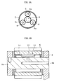
FIGS. 5A and 5B , the planetary gear mechanism includes a ring gear (internal gear) 2, asun gear 4, a plurality of pinions (planetary gears) 6, and acarrier 8. Thesun gear 4 is positioned at the center of thelarge ring gear 2, and the plurality ofpinions 6 are interposed between thering gear 2 and thesun gear 4. Thecarrier 8 includespinion shafts 8a, and eachpinion shaft 8a supports thepinion 6. Therefore, thepinions 6 can revolve about thesun gear 4 while rotating on their axes. - As illustrated in
FIG. 5B , each of thepinions 6 is supported on thepinion shaft 8a in a freely rotatable manner through intermediation of a needle roller andcage assembly 10. The needle roller andcage assembly 10 includes a large number ofneedle rollers 12 and acage 14. The needle roller andcage assembly 10 utilizes an outer circumferential surface of thepinion shaft 8a as an inner raceway surface and an inner circumferential surface of thepinion 6 as an outer raceway surface without using a bearing inner race or a bearing outer race. Thepinion shaft 8a has anoil lubrication hole 8b formed therein, for supplying lubricating oil. The planetary gear mechanism often has structure of lubricating in the needle roller andcage assembly 10 by drawing-in the lubricating oil through theoil lubrication hole 8b formed in thepinion shaft 8a as described above so as to be guided to the outer circumferential surface of thepinion shaft 8a. - The
pinion 6 is relatively easily distorted due to the action of a centrifugal force or a force applied from thesun gear 4 to thepinion shaft 8a. Due to such a condition, in a case of single-row roller, when thepinion shaft 8a is distorted, an edge stress is liable to be generated in an edge portion of theneedle roller 12. In addition, in the planetary gear mechanism for a transmission, a helical gear is used. The helical gear has a torsion angle, and hence a thrust is generated. The thrust acts on the bearing as a moment. With this, the gear is inclined, and hence the contact pressure of the roller edge portion is significantly increased, which is also a factor of the generation of the edge stress. In any case, the edge stress shortens the life of the bearing. - Patent Literature 1 discloses a technology of extending the life of the bearing by arranging the needle rollers in three rows or more and causing differences in roller length and crowning amount of the needle roller for each row. For example, the differences are set to such an extent that the roller length is shortened in an outer row than in an inner row (paragraph 0014 and
FIG. 4 of Patent Literature 1), and the crowning amount is increased in the outer row that in the inner row (paragraph 0016 and FIGS. 6 and 7 of Patent Literature 1).Patent Literature 2 discloses a planetary gear-type continuously variable transmission in which the planetary gear is supported by two needle bearings, in other words, a plurality of roller rows are provided (paragraphs 0028 and 0029 andFIG. 1 of Patent Literature 2). - The cage of the needle roller and cage assembly includes pockets for receiving the needle rollers, and in general, a relief portion is formed in each of four corners of the pocket mainly in order to relieve stress concentration. As disclosed in Patent Literature 3, the relief portion is normally formed through a drilling process or a milling process, and hence the relief portion often has an arc shape.
-
- Patent Literature 1:
JP 2005-172187 A - Patent Literature 2:
JP 2006-090458 A - Patent Literature 3:
JP 2009-068677 A - When the plurality of roller rows are provided as in
Patent Literatures 1 and 2, there is a problem in that the number of the assembling steps is increased. In addition, when causing differences in roller length and crowning amount for each roller row, it is necessary to pay close attention during the assembling in order not to mix the rollers having different roller lengths and crowning amounts, and hence the work efficiency is significantly degraded. - Further, during the rotation of the planetary gear mechanism, a centrifugal force, which is generated due to the revolution about the sun gear, acts on the needle rollers, and due to the centrifugal force, the needle rollers each apply a load to the cage. A centrifugal force generated due to the weight of the cage itself also acts on the cage, and due to the centrifugal force, the cage is pressed against the inner circumferential surface of the pinion to rotate together with the pinion. However, the needle rollers revolve at a speed about half of that of the pinion, and hence friction is caused between an outer circumferential surface of the cage (radially outer guide surface) and the inner circumferential surface of the pinion.
- Further, in the bearing to be used for supporting the pinion of the planetary gear mechanism, the pinion shaft may be distorted, and hence the edge stress is liable to be generated. In addition, the bearing often has such structure that the lubricating oil is difficult to be supplied thereto. Therefore, the roller end portion is liable to be damaged. To lubricate in the needle roller and cage assembly in the structure of drawing-in the lubricating oil into the oil lubrication hole in the pinion shaft as in
Patent Literatures 1 and 2, the lubricating oil, which passes through the oil lubrication hole so as to reach the outer circumferential surface of the pinion shaft, is required to further spread in a longitudinal direction of the needle roller, and hence the lubricating oil may not be sufficiently supplied to the entire needle roller. - Note that, the relief portion formed in each of the four corners of the pocket of the cage generally has an arc shape mainly for the purpose of relieving the stress as well as the process-related reason. In addition, the relief portion is required to avoid interference with the end portion (chamfered portion) of the needle roller, and hence has a limitation on the radius of curvature. For those reasons, the relief portion having the arc shape, which is formed in each of the four corners of the pocket, is less expected to contribute to the lubrication of the roller end portion.
- The present invention has an object to solve the above-mentioned problems inherent in the related-art needle roller and cage assembly. Specifically, the present invention has an obj ect to provide a needle roller and cage assembly, which is extended in life without complicating assembling work.
- In order to solve the problems, one embodiment of the present invention provides a needle roller and cage assembly comprising needle rollers being arranged in a single row and having a width dimension larger than a diameter thereof. Specifically, according to the one embodiment of the present invention, there is provided a needle roller and cage assembly, comprising: a large number of needle rollers arranged in a single row; and a cage having a width larger than a diameter thereof, the cage comprising: a pair of annular sections spaced apart from each other in an axial direction of the cage; and a plurality of pillar sections extending in the axial direction, for coupling the pair of annular sections to each other.
- The plurality of pillar sections each comprise: a roller retaining portion on a radially inner side with respect to a roller pitch circle diameter, the roller retaining portion on the radially inner side being formed at a center portion of each of the plurality of pillar sections in the axial direction; a roller retaining portion on a radially outer side with respect to the roller pitch circle diameter, the roller retaining portion on the radially outer side being formed at each end portion of the each of the plurality of pillar sections in the axial direction; and an oblique portion through which the roller retaining portion on the radially inner side and the roller retaining portion on the radially outer side are continuous with each other. The oblique portion comprises a first relief portion formed therein, for avoiding interference with each of the needle rollers.
- The plurality of adjacent pillar sections form pockets for receiving the needle rollers therebetween. Each of the pockets has a rectangular shape with its short sides being parallel to the pair of annular sections. The each of the pockets comprises a second relief portion in each of four corners thereof, the second relief portion being formed by partially cutting out the each oft he plurality of pillar sections. The second relief portion extends in the axial direction of the cage from a position at which one of the short sides of the each of the pockets is elongated in a circumferential direction of the cage to an outer end of the roller retaining portion on the radially outer side.
- A region having a dimension b (hatched part) in
FIG. 1B corresponds to a radially outer guide surface. Further, an outer end of the first relief portion corresponds to an inner end of the roller retaining portion on the radially outer side. The "outer end" herein indicates an end close to an end surface of the cage in the axial direction, and the "inner end" indicates an end opposite to the end surface of the cage in the axial direction. Therefore, when an axial dimension of the second relief portion is changed, the position of the outer end of the roller retaining portion on the radially outer side is changed, and therefore an axial dimension of the roller retaining portion on the radially outer side is also changed. - The needle roller and cage assembly according to the one embodiment of the present invention has the width larger than the diameter thereof, and hence the roller length is large . Therefore, the life can be extended without providing a plurality of roller rows. In addition, the rollers are arranged in the single row, and hence the assembling work is not complicated.
- The needle roller and cage assembly comprising the needle rollers being arranged in the single row and having the width larger than the diameter thereof is simplified in assembling than in a case where the plurality of roller rows are provided. However, the roller length is increased, and hence the needle rollers are skewed more significantly, with the result that slippage is liable to occur. That is, the needle roller and cage assembly having the width larger than the diameter thereof has harsh drawbacks as a bearing as compared to a general bearing. The above-mentioned problem of the skew, which is caused when the roller length is increased, is addressed by securing an interval between the roller retaining portions.
- Further, in place of the related-art general relief portion having a simple arc shape, the relief portion is formed in each of the four corners of the pocket having the rectangular shape in the cage so as to extend in the axial direction of the cage from the short side of the pocket to the outer end of the roller retaining portion on the radially outer side. With this, the opening area can be secured sufficiently. In this manner, oil lubrication performance of the roller end portion is improved. The lubricating oil is sufficiently supplied to a part of the roller end portion, at which the edge stress is liable to be generated, so as to form an oil film. In this manner, the life of the needle roller and cage assembly can be extended. That is, the relief portion increased in opening area is formed at a position of the pocket directly on the short side thereof, with the result that the lubricating oil is guided to a portion between the radially outer guide surface and an inner circumferential surface of the pinion through the relief portion. With this, the oil film can be formed between the outer circumferential surface (radially outer guide surface) of the cage and the inner circumferential surface of the pinion so as to reduce the friction, which also contributes to the extension of the life of the needle roller and cage assembly.
-
-
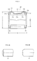
FIG. 1A is a developed view of a pocket portion of a cage. -
FIG. 1B is a schematic view of the pocket portion of the cage. -
FIG. 2A is a sectional view of an M-shaped cage. -
FIG. 2B is a sectional view of a V-shaped cage. -
FIG. 3 is a sectional view of a needle roller and cage assembly. -
FIG. 4A is a front view of a type-A needle roller. -
FIG. 4B is a front view of a type-F needle roller. -
FIG. 5A is a simplified view of a planetary gear device. -
FIG. 5B is a sectional view of a pinion portion ofFIG. 5A . - Now, an embodiment of the present invention is described in detail referring to the accompanying drawings.
- First, referring to
FIG. 3 , a needle roller andcage assembly 10 comprises a large number ofneedle rollers 12 arranged in a single row, and acage 14 into which the large number ofneedle rollers 12 are assembled. As illustrated inFIGS. 1A and 1B andFIGS. 2 , thecage 14 comprises a pair ofannular sections 16 spaced apart from each other in an axial direction, and a plurality ofpillar sections 18 extending in the axial direction, for coupling theannular sections 16 to each other. A width B of thecage 14 is larger than a diameter D thereof. When taking a specific example, it is preferred that the relationship between the width B and the diameter D satisfy D<B<2D. InFIG. 3 , reference symbol D denotes the diameter of thecage 14, and reference symbol B denotes the width of thecage 14. Hatched regions inFIG. 1B , that is, regions each ranging from theannular section 16 to a part of thepillar section 18 on an outer circumferential surface of thecage 14 are herein referred to as "radially outer guide surface". During rotation, thecage 14 is guided while the radially outer guide surface thereof is held in contact with an inner circumferential surface of a pinion 6 (FIG. 5B ), which is a so-called outer race guiding type. - The sectional shape of the
cage 14 may be an M-shape as illustrated inFIG. 2A or a V-shape as illustrated inFIG. 2B . The M-shape and the V-shape are different from each other only in that aninward flange 16a, which is formed on an outer end of each of theannular sections 16 in the M-shape, is not formed in the V-shape. - As already described, the
pillar section 18 of thecage 14 comprises aroller retaining portion 18a on a radially inner side, which is formed at a center portion thereof in the axial direction, and aroller retaining portion 18b on a radially outer side, which is formed at each end portion thereof in the axial direction. The expressions "radially inner side" and "radially outer side" herein indicate a radially inner side or a radially outer side with respect to a roller pitch circle diameter PCD (FIG. 3 ). That is, theroller retaining portion 18a on the radially inner side and theroller retaining portion 18b on the radially outer side are positioned opposite to each other across the roller pitch circle. Theroller retaining portion 18a on the radially inner side and theroller retaining portion 18b on the radially outer side are continuous with each other through anoblique portion 18c. Theoblique portion 18c comprises afirst relief portion 22 for avoiding interference with an outer circumferential surface of theneedle roller 12. An outer end of thefirst relief portion 22 corresponds to an inner end of theroller retaining portion 18b on the radially outer side. -
Pockets 20 for receiving theneedle rollers 12 are each formed between theadjacent pillar sections 18. Thepockets 20 are formed equiangularly, and theneedle roller 12 is received in each of thepockets 20. Thepocket 20 is formed through thecage 14 in a radial direction, and theneedle roller 12 partially protrudes from thecage 14. An outer circumferential surface of apinion shaft 8a (FIG. 5B ) serves as the inner raceway surface for theneedle rollers 12, and the inner circumferential surface of thepinion 6 serves as an outer raceway surface for theneedle rollers 12. Theneedle rollers 12 roll on those raceway surfaces. - As illustrated in
FIGS. 1A and 1B , each of thepockets 20 is configured to receive theneedle roller 12, and hence has a rectangular shape with its short sides being parallel to theannular sections 16. Asecond relief portion 24 is formed in each of four corners of thepocket 20 by partially cutting out thepillar sections 18. Thesecond relief portion 24 extends in the axial direction of thecage 14 from a position at which the short side of thepocket 20 is elongated in a circumferential direction to an outer end of theroller retaining portion 18a on the radially outer side. In the example illustrated inFIGS. 1A and 1B , thesecond relief portion 24 also has a rectangular shape with its long sides extending in parallel to the axial direction of thecage 14. Reference symbol L2 denotes an axial dimension of thesecond relief portion 24. Reference symbol L1 denotes an axial dimension from an outer end of thesecond relief portion 24, that is, the short side of thepocket 20 to the inner end of theroller retaining portion 18b on the radially outer side. - The "outer end" and "inner end" as used herein are expressions with one of both end surfaces of the cage being set as a reference. An end closer to the end surface is referred to as "outer end", and an end farther from the end surface is referred to as "inner end". When the axial dimension L2 of the
second relief portion 24 is changed, the position of the outer end of theroller retaining portion 18b on the radially outer side is changed, and therefore an axial dimension of theroller retaining portion 18b on the radially outer side (L1-L2) is also changed. - It is preferred that the axial dimension L2 of the
second relief portion 24 be 40% or more and 70% or less of the dimension L1. When the axial dimension L2 of thesecond relief portion 24 is less than 40% of the dimension L1, specifically, is 35% of the dimension L1, an effect (of extending life) due to the improvement in oil lubrication performance cannot be observed clearly. On the other hand, when the axial dimension L2 falls within a range of 40% or more and 80% or less of the dimension L1, the effect of extending life can be observed. However, when the axial dimension L2 exceeds 70% of the dimension L1, the length of theroller retaining portion 18b on the radially outer side becomes smaller, and hence the retaining force for theneedle roller 12 is reduced. In addition, when theneedle roller 12 is long, the self-weight of theneedle roller 12 is large accordingly. Therefore, theneedle roller 12 may fall off thecage 14 due to vibration. - The dimension L1 and the dimension L2 have such a relationship that, when the dimension L1 is increased, the dimension L2 is reduced. In view of the above, the lower limit of the axial dimension L2 of the
second relief portion 24 is set to 40% of the dimension L1, and accordingly, the axial dimension of theroller retaining portion 18a on the radially outer side is reduced. Theroller retaining portion 18a corresponds to a portion to be brought into contact with the outer circumferential surface of the needle roller, and hence is subjected to a process such as transfer pressing. Due to the process, a width surface of the pillar section may be deformed. Therefore, when the axial dimension of theroller retaining portion 18a is reduced, an adverse effect on the pillar section, which may be caused by the processing force generated due to the process on theroller retaining portion 18a, can be avoided. Further, when the axial dimension of theroller retaining portion 18a is excessively reduced, a trouble may be caused when retaining or guiding theneedle roller 12. Thus, the upper limit of the axial dimension L2 of thesecond relief portion 24 is kept to 70% of the dimension L1. With this, the axial dimension of theroller retaining portion 18a on the radially outer side is secured, and thus theneedle roller 12 is avoided from falling off thecage 14. - The
cage 24 is manufactured by press-forming a cylindrical material into an M-shape or a V-shape so as to punch out pockets, or in a case of a welded cage, the cost can be reduced. An overview of manufacturing steps of the welded cage is described as follows. - (a) As a material, band-like steel, which is obtained by shearing, with a slitter, a cold-rolled steel plate excellent in formability such as SPC into a predetermined width, is used.
- (b) The band-like steel is subjected to press working so that a basic sectional shape of the cage (M-shape or V shape) is formed.
- (c) Pockets are punched out so as to be formed at a predetermined pitch in a longitudinal direction of the band-like steel. After that, the band-like steel is cut into a predetermined length in consideration of a welding margin on each end.
- (d) The band-like steel is bent into a ring shape.
- (e) Both the end portions are brought into abutment against each other so as to be welded, to thereby obtain a product.
- The cage as the product obtained as described above is subj ected to heat treatment, such as nitrocarburizing treatment and carburizing-and-quenching, so as to remove strain caused due to the welding and form a hardened surface layer on a surface of the cage. In this manner, the abrasion resistance and the mechanical strength are enhanced.
- When the second relief portion is formed into an arc shape, and a width dimension b (
FIG. 1B ) of the radially outer guide surface of thecage 14 is set larger without changing a radius of curvature, the axial dimension of theroller retaining portion 18b on the radially outer side becomes larger. In this case, the amount of a process (transfer pressing or burnishing process), which is performed so as to form theroller retaining portion 18b, is increased, and hence the width surface of thepillar section 18 may be deformed. When the axial dimension of theroller retaining portion 18b is to set smaller, it is necessary that the radius of curvature of the second relief portion be set larger. As a result, a width of thepillar section 18 becomes smaller, and thus the strength of the cage is lowered. In view of the above, as thesecond relief portion 24, the relief portion of the present invention is formed so as to have a rectangular shape with its axial dimension increased with respect to a dimension of the cage in the circumferential direction in place of the related-art general relief portion having a uniform radius of curvature. When the second relief portion is formed into the above-mentioned shape so that the axial dimension L2 of thesecond relief portion 24 is changed, the position of the outer end of theroller retaining portion 18a on the radially outer side as well as the width b of the radially outer guide surface can be adjusted. - Note that, when the width b of the radially outer guide surface of the
cage 14 is set smaller, the above-mentioned problems can be solved. However, in the application that involves rotation and revolution as in a case of the planetary gear mechanism, the load to be applied to a radially outer surface of thecage 14 is large, and hence, when the width b of the radially outer guide surface of thecage 14 is set smaller, thecage 14 may be damaged. Therefore, a width b+b of the radially outer guide surfaces is secured so as to be 35% or more of the width B of thecage 14. When the width b of the radially outer guide surface is increased, the outer end of theroller retaining portion 18a on the radially outer side is shifted inward. However, when the outer end of theroller retaining portion 18a on the radially outer side is shifted excessively inward, an interval between theroller retaining portions 18a on both sides becomes smaller, and hence theneedle rollers 12 may be skewed, thus leading to an early damage. Therefore, the upper limit of the width b+b of the radially outer guide surfaces is set to 60% of the width B of thecage 14. In short, it is preferred that the axial dimension b+b of the radially outer guide surfaces of thecage 14 be set to 35% or more and 60% or less of the width B of the cage. - The
needle roller 12 comprises a type-A needle roller 12 having a rounded end surface as illustrated inFIG. 4A and a type-F needle roller 12 having a planer end surface as illustrated inFIG. 4B . When the type-A needle roller 12 is employed, a clearance is secured between the end surface of theneedle roller 12 and the short side of thepocket 20 of thecage 14 . In addition, the clearance has a larger area than in a case of employing the type-F needle roller having the planer end surface. Further, thesecond relief portion 24 is positioned so as to overlap with the clearance, and hence a sufficient amount of the lubricating oil is supplied to an end portion of theneedle roller 12. Further, the lubricating oil, which passes from the radially inner side to the radially outer side through thesecond relief portion 24, is supplied to a portion between the radially outer guide surface and the inner circumferential surface of the pinion 6 (FIG. 5B ), to thereby perform the lubrication. - As described above, in the above-mentioned embodiment, the type-A is employed for the end surface of the
needle roller 12, and thesecond relief portion 24 of thepocket 20 of thecage 14 is elongated in the axial direction. As a result, the sectional area of a space, which is secured so as to extend between the end portion of theneedle roller 12 and thecage 14 in the radial direction, is increased, and the oil lubrication performance of the lubricating oil is improved. Therefore, the lubricating oil is sufficiently fed to the end portion of theneedle roller 12, at which the edge stress is liable to be generated, so as to form an oil film. In this manner, the life of the bearing can be extended. Further, the oil lubrication performance is enhanced, and thus even a singleoil lubrication hole 8b formed in thepinion shaft 8a (FIG. 5B ) is sufficient. The process of forming theoil lubrication hole 8b in thepinion shaft 8a is minimized, and hence the cost can be reduced. -
- 10
- needle roller and cage assembly
- 12
- needle roller
- 14
- cage
- 16
- annular section
- 16a
- inward flange
- 18
- pillar section
- 18a
- roller retaining portion (radially inner side)
- 18b
- roller retaining portion (radially outer side)
- 18c
- oblique portion
- 20
- 22
- first relief portion
- 24
- second relief portion
Claims (6)
- A needle roller and cage assembly, comprising:a large number of needle rollers arranged in a single row; anda cage having a width dimension larger than a diameter thereof, the cage comprising:a pair of annular sections spaced apart from each other in an axial direction of the cage; anda plurality of pillar sections extending in the axial direction, for coupling the pair of annular sections to each other, the plurality of pillar sections each comprising:a roller retaining portion on a radially inner side with respect to a roller pitch circle diameter, the roller retaining portion on the radially inner side being formed at a center portion of each of the plurality of pillar sections in the axial direction;a roller retaining portion on a radially outer side with respect to the roller pitch circle diameter, the roller retaining portion on the radially outer side being formed at each end portion of the each of the plurality of pillar sections in the axial direction; andan oblique portion through which the roller retaining portion on the radially inner side and the roller retaining portion on the radially outer side are continuous with each other, the oblique portion comprising a first relief portion formed therein, for avoiding interference with each of the needle rollers,the plurality of adjacent pillar sections forming pockets for receiving the needle rollers therebetween,each of the pockets having a rectangular shape with its short sides being parallel to the pair of annular sections,the each of the pockets comprising a second relief portion in each of four corners thereof, the second relief portion being formed by partially cutting out the each of the plurality of pillar sections,the second relief portion extending in the axial direction of the cage from a position at which one of the short sides of the each of the pockets is elongated in a circumferential direction of the cage to an outer end of the roller retaining portion on the radially outer side.
- The needle roller and cage assembly according to claim 1, wherein a sectional shape of the cage comprises an M-shape or a V-shape.
- The needle roller and cage assembly according to claim 1 or 2, wherein an axial dimension of the second relief portion is set to 40% or more and 70% or less of an axial dimension from the one of the short sides of the each of the pockets to an inner end of the roller retaining portion on the radially outer side.
- The needle roller and cage assembly according to any one of claims 1, 2, and 3, wherein an axial dimension of a radially outer guide surface of the cage is set to 35% or more and 60% or less of a total width of the cage.
- The needle roller and cage assembly according to any one of claims 1 to 4, wherein an end surface of the each of the needle rollers comprises a rounded surface.
- The needle roller and cage assembly according to any one of claims 1 to 5, wherein the needle roller and cage assembly is used for supporting a pinion of a planetary gear mechanism.
Applications Claiming Priority (2)
| Application Number | Priority Date | Filing Date | Title |
|---|---|---|---|
| JP2012223085A JP6497833B2 (en) | 2012-10-05 | 2012-10-05 | Needle roller with cage |
| PCT/JP2013/073947 WO2014054376A1 (en) | 2012-10-05 | 2013-09-05 | Retainer-equipped needle rollers |
Publications (3)
| Publication Number | Publication Date |
|---|---|
| EP2905488A1 true EP2905488A1 (en) | 2015-08-12 |
| EP2905488A4 EP2905488A4 (en) | 2016-03-02 |
| EP2905488B1 EP2905488B1 (en) | 2020-11-11 |
Family
ID=50434707
Family Applications (1)
| Application Number | Title | Priority Date | Filing Date |
|---|---|---|---|
| EP13843778.5A Not-in-force EP2905488B1 (en) | 2012-10-05 | 2013-09-05 | Needle roller and cage assembly |
Country Status (6)
| Country | Link |
|---|---|
| US (1) | US9618041B2 (en) |
| EP (1) | EP2905488B1 (en) |
| JP (1) | JP6497833B2 (en) |
| KR (1) | KR102078048B1 (en) |
| CN (1) | CN104662313B (en) |
| WO (1) | WO2014054376A1 (en) |
Families Citing this family (12)
| Publication number | Priority date | Publication date | Assignee | Title |
|---|---|---|---|---|
| JP6631066B2 (en) * | 2015-07-24 | 2020-01-15 | 日本精工株式会社 | Method for manufacturing cage for radial needle bearing |
| JP2017053461A (en) * | 2015-09-10 | 2017-03-16 | 株式会社ハーモニック・ドライブ・システムズ | Planetary gear train |
| JP2017053448A (en) * | 2015-09-10 | 2017-03-16 | Ntn株式会社 | Roller bearing |
| CN110382887B (en) * | 2017-03-06 | 2021-05-25 | Ntn株式会社 | Needle roller with retainer and planetary gear mechanism support structure having the same |
| KR102508641B1 (en) * | 2017-03-06 | 2023-03-10 | 엔티엔 가부시키가이샤 | Needle-shaped roller with retainer and planetary gear mechanism support structure provided therewith |
| JP6932012B2 (en) * | 2017-03-06 | 2021-09-08 | Ntn株式会社 | Needle roller with cage and planetary gear mechanism support structure with it |
| JP6804341B2 (en) * | 2017-03-06 | 2020-12-23 | Ntn株式会社 | Needle roller with cage and planetary gear mechanism support structure with it |
| JP7089369B2 (en) * | 2018-01-09 | 2022-06-22 | Ntn株式会社 | Roller with cage and planetary gear support structure |
| JP7003783B2 (en) * | 2018-03-27 | 2022-01-21 | 株式会社ジェイテクト | Cage and roller |
| JP2020026874A (en) * | 2018-08-17 | 2020-02-20 | Ntn株式会社 | Roller with cage and planetary gear support structure |
| JP7597540B2 (en) * | 2020-09-24 | 2024-12-10 | Ntn株式会社 | Method of inspecting welded cage for roller bearing, roller with cage, and welded cage for bearing |
| JP2025111206A (en) * | 2024-01-17 | 2025-07-30 | Ntn株式会社 | Needle roller and cage assembly |
Family Cites Families (28)
| Publication number | Priority date | Publication date | Assignee | Title |
|---|---|---|---|---|
| DE2147170A1 (en) * | 1971-09-22 | 1973-03-29 | Schaeffler Ohg Industriewerk | METHOD OF MANUFACTURING A SHEET CAGE FOR CYLINDRICAL ROLLED BODIES |
| US3892447A (en) * | 1972-12-15 | 1975-07-01 | Peregrinus Gruber | Plastic cages for roller bearings |
| JPH0673441A (en) | 1992-08-28 | 1994-03-15 | Toyota Motor Corp | Highly workable steel sheet with excellent strength characteristics by irradiation with a high-density energy source |
| JPH0673441U (en) * | 1993-03-30 | 1994-10-18 | エヌティエヌ株式会社 | Needle roller bearing cage |
| JP2912532B2 (en) * | 1993-09-30 | 1999-06-28 | エヌティエヌ株式会社 | Needle roller with cage |
| JPH11108065A (en) * | 1997-08-06 | 1999-04-20 | Ntn Corp | Needle roller bearing |
| US6007254A (en) * | 1997-09-29 | 1999-12-28 | Ntn Corporation | Needle roller bearing |
| DE19754836A1 (en) * | 1997-12-10 | 1999-06-17 | Schaeffler Waelzlager Ohg | Needle bearing cage and process for its manufacture |
| DE10109953A1 (en) * | 2000-05-09 | 2001-11-15 | Schaeffler Waelzlager Ohg | Roller ring has oppositely disposed end faces of roller pockets and oppositely disposed end faces of cylindrical rollers rounded on outside |
| DE10126217A1 (en) | 2001-05-30 | 2002-12-05 | Ina Schaeffler Kg | Rolling bearing cage |
| JP2003214439A (en) * | 2002-01-17 | 2003-07-30 | Nsk Ltd | Bearing for a/t |
| JP2005172187A (en) | 2003-12-15 | 2005-06-30 | Nsk Ltd | Needle bearing and planetary gear mechanism |
| JP3996154B2 (en) | 2004-09-24 | 2007-10-24 | ジヤトコ株式会社 | Lubrication structure in planetary gear mechanism |
| JP4606128B2 (en) * | 2004-11-11 | 2011-01-05 | 宇都宮機器株式会社 | Method for manufacturing roller bearing cage |
| CN101137853B (en) * | 2005-03-14 | 2010-09-22 | Ntn株式会社 | Needle roller bearing |
| DE602006020117D1 (en) | 2005-03-14 | 2011-03-31 | Honda Motor Co Ltd | NADELLAGER AND MANUFACTURING METHOD THEREFOR |
| JP2007064305A (en) * | 2005-08-30 | 2007-03-15 | Ntn Corp | Planetary gear mechanism and automatic transmission |
| JP2007071344A (en) * | 2005-09-08 | 2007-03-22 | Ntn Corp | Outboard motor engine and crank shaft support structure for outboard motor engine |
| JP2008215605A (en) * | 2007-02-05 | 2008-09-18 | Nsk Ltd | Radial needle bearing retainer, method of manufacturing the same, and radial needle bearing |
| JP5040401B2 (en) * | 2007-03-30 | 2012-10-03 | 日本精工株式会社 | Method for manufacturing cage for radial needle bearing |
| DE102007030217A1 (en) * | 2007-06-29 | 2009-01-08 | Schaeffler Kg | Cage |
| JP2009041757A (en) * | 2007-08-13 | 2009-02-26 | Nsk Ltd | Method for manufacturing metal cage |
| JP5128216B2 (en) * | 2007-09-18 | 2013-01-23 | Ntn株式会社 | Cage for needle roller with cage and needle roller with cage |
| JP5012438B2 (en) * | 2007-11-09 | 2012-08-29 | 日本精工株式会社 | Needle roller bearing |
| JP5499451B2 (en) * | 2008-09-02 | 2014-05-21 | 株式会社ジェイテクト | Roller bearing of planetary gear mechanism |
| JP5169719B2 (en) * | 2008-10-17 | 2013-03-27 | 株式会社ジェイテクト | Roller bearing of planetary gear mechanism |
| JP5353444B2 (en) * | 2009-05-25 | 2013-11-27 | 日本精工株式会社 | Radial needle bearing cage and radial needle bearing |
| JP2014149076A (en) | 2013-01-10 | 2014-08-21 | Nsk Ltd | Retainer for radial needle bearing and manufacturing method thereof |
-
2012
- 2012-10-05 JP JP2012223085A patent/JP6497833B2/en active Active
-
2013
- 2013-09-05 EP EP13843778.5A patent/EP2905488B1/en not_active Not-in-force
- 2013-09-05 KR KR1020157009533A patent/KR102078048B1/en active Active
- 2013-09-05 WO PCT/JP2013/073947 patent/WO2014054376A1/en not_active Ceased
- 2013-09-05 US US14/428,020 patent/US9618041B2/en active Active
- 2013-09-05 CN CN201380049739.5A patent/CN104662313B/en active Active
Also Published As
| Publication number | Publication date |
|---|---|
| JP2014074471A (en) | 2014-04-24 |
| JP6497833B2 (en) | 2019-04-10 |
| KR102078048B1 (en) | 2020-02-17 |
| EP2905488B1 (en) | 2020-11-11 |
| US9618041B2 (en) | 2017-04-11 |
| CN104662313B (en) | 2018-01-02 |
| US20150252849A1 (en) | 2015-09-10 |
| EP2905488A4 (en) | 2016-03-02 |
| CN104662313A (en) | 2015-05-27 |
| WO2014054376A1 (en) | 2014-04-10 |
| KR20150060766A (en) | 2015-06-03 |
Similar Documents
| Publication | Publication Date | Title |
|---|---|---|
| EP2905488B1 (en) | Needle roller and cage assembly | |
| US8322931B2 (en) | Rotation support apparatus | |
| US7513043B2 (en) | Support structure carrying thrust load of transmission, method of manufacturing thereof and thrust needle roller bearing | |
| EP2562441A1 (en) | Decelerating device | |
| US11137023B2 (en) | Roller and cage assembly and planetary gear support structure | |
| EP1903230B1 (en) | Rolling bearing apparatus | |
| JP5128216B2 (en) | Cage for needle roller with cage and needle roller with cage | |
| JP5012438B2 (en) | Needle roller bearing | |
| EP3839279A1 (en) | Retainer-equipped rollers and planetary gear support structure | |
| EP3693626B1 (en) | Retainer for rolling bearing | |
| KR102508641B1 (en) | Needle-shaped roller with retainer and planetary gear mechanism support structure provided therewith | |
| US20050064977A1 (en) | Roller/retainer assembly for planetary gear and planetary gears support using the same | |
| JP2017058022A (en) | Supporting structure for planetary gear | |
| EP2017487A2 (en) | Tapered roller bearing with lubricant grooves on the cage | |
| JP2020118177A (en) | Needle roller with double row holder | |
| JP2005291445A (en) | Tapered roller bearing | |
| KR102546430B1 (en) | Needle rollers with cages and planetary gear mechanism support structure provided therewith | |
| WO2024111513A1 (en) | Retainer, retainer-equipped needle roller employing said retainer, and bearing device | |
| JP2005016710A (en) | Needle roller bearing | |
| JP2015092088A (en) | Cage for radial roller bearing, and radial roller bearing | |
| JP2008240850A (en) | Tapered roller bearing | |
| JP2010270884A (en) | Radial needle bearing cage and radial needle bearing | |
| WO2018181016A1 (en) | Cylindrical roller bearing, retainer, and retainer manufacturing method | |
| JP7075324B2 (en) | Cage for roller bearings and needle roller with cage | |
| JP2019060464A (en) | Retainer for cylindrical roller bearing |
Legal Events
| Date | Code | Title | Description |
|---|---|---|---|
| PUAI | Public reference made under article 153(3) epc to a published international application that has entered the european phase |
Free format text: ORIGINAL CODE: 0009012 |
|
| 17P | Request for examination filed |
Effective date: 20150424 |
|
| AK | Designated contracting states |
Kind code of ref document: A1 Designated state(s): AL AT BE BG CH CY CZ DE DK EE ES FI FR GB GR HR HU IE IS IT LI LT LU LV MC MK MT NL NO PL PT RO RS SE SI SK SM TR |
|
| AX | Request for extension of the european patent |
Extension state: BA ME |
|
| DAX | Request for extension of the european patent (deleted) | ||
| RA4 | Supplementary search report drawn up and despatched (corrected) |
Effective date: 20160203 |
|
| RIC1 | Information provided on ipc code assigned before grant |
Ipc: F16C 19/46 20060101ALI20160128BHEP Ipc: F16C 33/54 20060101AFI20160128BHEP Ipc: F16H 57/08 20060101ALI20160128BHEP Ipc: F16C 19/26 20060101ALI20160128BHEP Ipc: F16C 33/46 20060101ALI20160128BHEP Ipc: F16C 33/66 20060101ALI20160128BHEP |
|
| STAA | Information on the status of an ep patent application or granted ep patent |
Free format text: STATUS: EXAMINATION IS IN PROGRESS |
|
| 17Q | First examination report despatched |
Effective date: 20170825 |
|
| GRAP | Despatch of communication of intention to grant a patent |
Free format text: ORIGINAL CODE: EPIDOSNIGR1 |
|
| STAA | Information on the status of an ep patent application or granted ep patent |
Free format text: STATUS: GRANT OF PATENT IS INTENDED |
|
| INTG | Intention to grant announced |
Effective date: 20200507 |
|
| GRAS | Grant fee paid |
Free format text: ORIGINAL CODE: EPIDOSNIGR3 |
|
| RIN1 | Information on inventor provided before grant (corrected) |
Inventor name: FUKAMI RINO Inventor name: KAWAI HIROMITSU |
|
| GRAA | (expected) grant |
Free format text: ORIGINAL CODE: 0009210 |
|
| STAA | Information on the status of an ep patent application or granted ep patent |
Free format text: STATUS: THE PATENT HAS BEEN GRANTED |
|
| AK | Designated contracting states |
Kind code of ref document: B1 Designated state(s): AL AT BE BG CH CY CZ DE DK EE ES FI FR GB GR HR HU IE IS IT LI LT LU LV MC MK MT NL NO PL PT RO RS SE SI SK SM TR |
|
| REG | Reference to a national code |
Ref country code: GB Ref legal event code: FG4D |
|
| REG | Reference to a national code |
Ref country code: CH Ref legal event code: EP |
|
| REG | Reference to a national code |
Ref country code: AT Ref legal event code: REF Ref document number: 1333763 Country of ref document: AT Kind code of ref document: T Effective date: 20201115 |
|
| REG | Reference to a national code |
Ref country code: DE Ref legal event code: R096 Ref document number: 602013074037 Country of ref document: DE |
|
| REG | Reference to a national code |
Ref country code: IE Ref legal event code: FG4D |
|
| REG | Reference to a national code |
Ref country code: NL Ref legal event code: MP Effective date: 20201111 |
|
| REG | Reference to a national code |
Ref country code: AT Ref legal event code: MK05 Ref document number: 1333763 Country of ref document: AT Kind code of ref document: T Effective date: 20201111 |
|
| PG25 | Lapsed in a contracting state [announced via postgrant information from national office to epo] |
Ref country code: GR Free format text: LAPSE BECAUSE OF FAILURE TO SUBMIT A TRANSLATION OF THE DESCRIPTION OR TO PAY THE FEE WITHIN THE PRESCRIBED TIME-LIMIT Effective date: 20210212 Ref country code: FI Free format text: LAPSE BECAUSE OF FAILURE TO SUBMIT A TRANSLATION OF THE DESCRIPTION OR TO PAY THE FEE WITHIN THE PRESCRIBED TIME-LIMIT Effective date: 20201111 Ref country code: RS Free format text: LAPSE BECAUSE OF FAILURE TO SUBMIT A TRANSLATION OF THE DESCRIPTION OR TO PAY THE FEE WITHIN THE PRESCRIBED TIME-LIMIT Effective date: 20201111 Ref country code: PT Free format text: LAPSE BECAUSE OF FAILURE TO SUBMIT A TRANSLATION OF THE DESCRIPTION OR TO PAY THE FEE WITHIN THE PRESCRIBED TIME-LIMIT Effective date: 20210311 Ref country code: NO Free format text: LAPSE BECAUSE OF FAILURE TO SUBMIT A TRANSLATION OF THE DESCRIPTION OR TO PAY THE FEE WITHIN THE PRESCRIBED TIME-LIMIT Effective date: 20210211 |
|
| PG25 | Lapsed in a contracting state [announced via postgrant information from national office to epo] |
Ref country code: SE Free format text: LAPSE BECAUSE OF FAILURE TO SUBMIT A TRANSLATION OF THE DESCRIPTION OR TO PAY THE FEE WITHIN THE PRESCRIBED TIME-LIMIT Effective date: 20201111 Ref country code: IS Free format text: LAPSE BECAUSE OF FAILURE TO SUBMIT A TRANSLATION OF THE DESCRIPTION OR TO PAY THE FEE WITHIN THE PRESCRIBED TIME-LIMIT Effective date: 20210311 Ref country code: LV Free format text: LAPSE BECAUSE OF FAILURE TO SUBMIT A TRANSLATION OF THE DESCRIPTION OR TO PAY THE FEE WITHIN THE PRESCRIBED TIME-LIMIT Effective date: 20201111 Ref country code: PL Free format text: LAPSE BECAUSE OF FAILURE TO SUBMIT A TRANSLATION OF THE DESCRIPTION OR TO PAY THE FEE WITHIN THE PRESCRIBED TIME-LIMIT Effective date: 20201111 Ref country code: BG Free format text: LAPSE BECAUSE OF FAILURE TO SUBMIT A TRANSLATION OF THE DESCRIPTION OR TO PAY THE FEE WITHIN THE PRESCRIBED TIME-LIMIT Effective date: 20210211 Ref country code: AT Free format text: LAPSE BECAUSE OF FAILURE TO SUBMIT A TRANSLATION OF THE DESCRIPTION OR TO PAY THE FEE WITHIN THE PRESCRIBED TIME-LIMIT Effective date: 20201111 |
|
| REG | Reference to a national code |
Ref country code: LT Ref legal event code: MG9D |
|
| PG25 | Lapsed in a contracting state [announced via postgrant information from national office to epo] |
Ref country code: HR Free format text: LAPSE BECAUSE OF FAILURE TO SUBMIT A TRANSLATION OF THE DESCRIPTION OR TO PAY THE FEE WITHIN THE PRESCRIBED TIME-LIMIT Effective date: 20201111 |
|
| PG25 | Lapsed in a contracting state [announced via postgrant information from national office to epo] |
Ref country code: SK Free format text: LAPSE BECAUSE OF FAILURE TO SUBMIT A TRANSLATION OF THE DESCRIPTION OR TO PAY THE FEE WITHIN THE PRESCRIBED TIME-LIMIT Effective date: 20201111 Ref country code: RO Free format text: LAPSE BECAUSE OF FAILURE TO SUBMIT A TRANSLATION OF THE DESCRIPTION OR TO PAY THE FEE WITHIN THE PRESCRIBED TIME-LIMIT Effective date: 20201111 Ref country code: LT Free format text: LAPSE BECAUSE OF FAILURE TO SUBMIT A TRANSLATION OF THE DESCRIPTION OR TO PAY THE FEE WITHIN THE PRESCRIBED TIME-LIMIT Effective date: 20201111 Ref country code: SM Free format text: LAPSE BECAUSE OF FAILURE TO SUBMIT A TRANSLATION OF THE DESCRIPTION OR TO PAY THE FEE WITHIN THE PRESCRIBED TIME-LIMIT Effective date: 20201111 Ref country code: EE Free format text: LAPSE BECAUSE OF FAILURE TO SUBMIT A TRANSLATION OF THE DESCRIPTION OR TO PAY THE FEE WITHIN THE PRESCRIBED TIME-LIMIT Effective date: 20201111 Ref country code: CZ Free format text: LAPSE BECAUSE OF FAILURE TO SUBMIT A TRANSLATION OF THE DESCRIPTION OR TO PAY THE FEE WITHIN THE PRESCRIBED TIME-LIMIT Effective date: 20201111 |
|
| REG | Reference to a national code |
Ref country code: DE Ref legal event code: R097 Ref document number: 602013074037 Country of ref document: DE |
|
| PG25 | Lapsed in a contracting state [announced via postgrant information from national office to epo] |
Ref country code: DK Free format text: LAPSE BECAUSE OF FAILURE TO SUBMIT A TRANSLATION OF THE DESCRIPTION OR TO PAY THE FEE WITHIN THE PRESCRIBED TIME-LIMIT Effective date: 20201111 |
|
| PLBE | No opposition filed within time limit |
Free format text: ORIGINAL CODE: 0009261 |
|
| STAA | Information on the status of an ep patent application or granted ep patent |
Free format text: STATUS: NO OPPOSITION FILED WITHIN TIME LIMIT |
|
| 26N | No opposition filed |
Effective date: 20210812 |
|
| PG25 | Lapsed in a contracting state [announced via postgrant information from national office to epo] |
Ref country code: NL Free format text: LAPSE BECAUSE OF FAILURE TO SUBMIT A TRANSLATION OF THE DESCRIPTION OR TO PAY THE FEE WITHIN THE PRESCRIBED TIME-LIMIT Effective date: 20201111 Ref country code: AL Free format text: LAPSE BECAUSE OF FAILURE TO SUBMIT A TRANSLATION OF THE DESCRIPTION OR TO PAY THE FEE WITHIN THE PRESCRIBED TIME-LIMIT Effective date: 20201111 |
|
| PGFP | Annual fee paid to national office [announced via postgrant information from national office to epo] |
Ref country code: IT Payment date: 20210930 Year of fee payment: 9 Ref country code: FR Payment date: 20210927 Year of fee payment: 9 |
|
| PG25 | Lapsed in a contracting state [announced via postgrant information from national office to epo] |
Ref country code: ES Free format text: LAPSE BECAUSE OF FAILURE TO SUBMIT A TRANSLATION OF THE DESCRIPTION OR TO PAY THE FEE WITHIN THE PRESCRIBED TIME-LIMIT Effective date: 20201111 Ref country code: SI Free format text: LAPSE BECAUSE OF FAILURE TO SUBMIT A TRANSLATION OF THE DESCRIPTION OR TO PAY THE FEE WITHIN THE PRESCRIBED TIME-LIMIT Effective date: 20201111 |
|
| PGFP | Annual fee paid to national office [announced via postgrant information from national office to epo] |
Ref country code: DE Payment date: 20210914 Year of fee payment: 9 |
|
| REG | Reference to a national code |
Ref country code: CH Ref legal event code: PL |
|
| REG | Reference to a national code |
Ref country code: BE Ref legal event code: MM Effective date: 20210930 |
|
| GBPC | Gb: european patent ceased through non-payment of renewal fee |
Effective date: 20210905 |
|
| PG25 | Lapsed in a contracting state [announced via postgrant information from national office to epo] |
Ref country code: IS Free format text: LAPSE BECAUSE OF FAILURE TO SUBMIT A TRANSLATION OF THE DESCRIPTION OR TO PAY THE FEE WITHIN THE PRESCRIBED TIME-LIMIT Effective date: 20210311 Ref country code: MC Free format text: LAPSE BECAUSE OF FAILURE TO SUBMIT A TRANSLATION OF THE DESCRIPTION OR TO PAY THE FEE WITHIN THE PRESCRIBED TIME-LIMIT Effective date: 20201111 |
|
| PG25 | Lapsed in a contracting state [announced via postgrant information from national office to epo] |
Ref country code: LU Free format text: LAPSE BECAUSE OF NON-PAYMENT OF DUE FEES Effective date: 20210905 Ref country code: IE Free format text: LAPSE BECAUSE OF NON-PAYMENT OF DUE FEES Effective date: 20210905 Ref country code: GB Free format text: LAPSE BECAUSE OF NON-PAYMENT OF DUE FEES Effective date: 20210905 Ref country code: BE Free format text: LAPSE BECAUSE OF NON-PAYMENT OF DUE FEES Effective date: 20210930 |
|
| PG25 | Lapsed in a contracting state [announced via postgrant information from national office to epo] |
Ref country code: LI Free format text: LAPSE BECAUSE OF NON-PAYMENT OF DUE FEES Effective date: 20210930 Ref country code: CH Free format text: LAPSE BECAUSE OF NON-PAYMENT OF DUE FEES Effective date: 20210930 |
|
| REG | Reference to a national code |
Ref country code: DE Ref legal event code: R119 Ref document number: 602013074037 Country of ref document: DE |
|
| PG25 | Lapsed in a contracting state [announced via postgrant information from national office to epo] |
Ref country code: HU Free format text: LAPSE BECAUSE OF FAILURE TO SUBMIT A TRANSLATION OF THE DESCRIPTION OR TO PAY THE FEE WITHIN THE PRESCRIBED TIME-LIMIT; INVALID AB INITIO Effective date: 20130905 |
|
| PG25 | Lapsed in a contracting state [announced via postgrant information from national office to epo] |
Ref country code: CY Free format text: LAPSE BECAUSE OF FAILURE TO SUBMIT A TRANSLATION OF THE DESCRIPTION OR TO PAY THE FEE WITHIN THE PRESCRIBED TIME-LIMIT Effective date: 20201111 |
|
| PG25 | Lapsed in a contracting state [announced via postgrant information from national office to epo] |
Ref country code: FR Free format text: LAPSE BECAUSE OF NON-PAYMENT OF DUE FEES Effective date: 20220930 Ref country code: DE Free format text: LAPSE BECAUSE OF NON-PAYMENT OF DUE FEES Effective date: 20230401 |
|
| PG25 | Lapsed in a contracting state [announced via postgrant information from national office to epo] |
Ref country code: IT Free format text: LAPSE BECAUSE OF NON-PAYMENT OF DUE FEES Effective date: 20220905 |
|
| PG25 | Lapsed in a contracting state [announced via postgrant information from national office to epo] |
Ref country code: MK Free format text: LAPSE BECAUSE OF FAILURE TO SUBMIT A TRANSLATION OF THE DESCRIPTION OR TO PAY THE FEE WITHIN THE PRESCRIBED TIME-LIMIT Effective date: 20201111 |
|
| PG25 | Lapsed in a contracting state [announced via postgrant information from national office to epo] |
Ref country code: TR Free format text: LAPSE BECAUSE OF FAILURE TO SUBMIT A TRANSLATION OF THE DESCRIPTION OR TO PAY THE FEE WITHIN THE PRESCRIBED TIME-LIMIT Effective date: 20201111 |
|
| PG25 | Lapsed in a contracting state [announced via postgrant information from national office to epo] |
Ref country code: MT Free format text: LAPSE BECAUSE OF FAILURE TO SUBMIT A TRANSLATION OF THE DESCRIPTION OR TO PAY THE FEE WITHIN THE PRESCRIBED TIME-LIMIT Effective date: 20201111 |