EP2905391A1 - Dübel, Setzwerkzeug und Verfahren zur Befestigung von Dämmstoffen - Google Patents
Dübel, Setzwerkzeug und Verfahren zur Befestigung von Dämmstoffen Download PDFInfo
- Publication number
- EP2905391A1 EP2905391A1 EP15000114.7A EP15000114A EP2905391A1 EP 2905391 A1 EP2905391 A1 EP 2905391A1 EP 15000114 A EP15000114 A EP 15000114A EP 2905391 A1 EP2905391 A1 EP 2905391A1
- Authority
- EP
- European Patent Office
- Prior art keywords
- dowel
- setting tool
- screw
- retaining plate
- setting
- Prior art date
- Legal status (The legal status is an assumption and is not a legal conclusion. Google has not performed a legal analysis and makes no representation as to the accuracy of the status listed.)
- Granted
Links
Images




Classifications
-
- E—FIXED CONSTRUCTIONS
- E04—BUILDING
- E04B—GENERAL BUILDING CONSTRUCTIONS; WALLS, e.g. PARTITIONS; ROOFS; FLOORS; CEILINGS; INSULATION OR OTHER PROTECTION OF BUILDINGS
- E04B1/00—Constructions in general; Structures which are not restricted either to walls, e.g. partitions, or floors or ceilings or roofs
- E04B1/62—Insulation or other protection; Elements or use of specified material therefor
- E04B1/74—Heat, sound or noise insulation, absorption, or reflection; Other building methods affording favourable thermal or acoustical conditions, e.g. accumulating of heat within walls
- E04B1/76—Heat, sound or noise insulation, absorption, or reflection; Other building methods affording favourable thermal or acoustical conditions, e.g. accumulating of heat within walls specifically with respect to heat only
- E04B1/762—Exterior insulation of exterior walls
- E04B1/7629—Details of the mechanical connection of the insulation to the wall
- E04B1/7633—Dowels with enlarged insulation retaining head
-
- F—MECHANICAL ENGINEERING; LIGHTING; HEATING; WEAPONS; BLASTING
- F16—ENGINEERING ELEMENTS AND UNITS; GENERAL MEASURES FOR PRODUCING AND MAINTAINING EFFECTIVE FUNCTIONING OF MACHINES OR INSTALLATIONS; THERMAL INSULATION IN GENERAL
- F16B—DEVICES FOR FASTENING OR SECURING CONSTRUCTIONAL ELEMENTS OR MACHINE PARTS TOGETHER, e.g. NAILS, BOLTS, CIRCLIPS, CLAMPS, CLIPS OR WEDGES; JOINTS OR JOINTING
- F16B13/00—Dowels or other devices fastened in walls or the like by inserting them in holes made therein for that purpose
- F16B13/02—Dowels or other devices fastened in walls or the like by inserting them in holes made therein for that purpose in one piece with protrusions or ridges on the shaft
-
- E—FIXED CONSTRUCTIONS
- E04—BUILDING
- E04D—ROOF COVERINGS; SKY-LIGHTS; GUTTERS; ROOF-WORKING TOOLS
- E04D15/00—Apparatus or tools for roof working
-
- E—FIXED CONSTRUCTIONS
- E04—BUILDING
- E04F—FINISHING WORK ON BUILDINGS, e.g. STAIRS, FLOORS
- E04F13/00—Coverings or linings, e.g. for walls or ceilings
- E04F13/07—Coverings or linings, e.g. for walls or ceilings composed of covering or lining elements; Sub-structures therefor; Fastening means therefor
- E04F13/21—Fastening means specially adapted for covering or lining elements
Definitions
- the invention relates to a dowel with the features of the preamble of claim 1 and a setting method for fixing insulating materials with the features of the preamble of claim 4.
- FIGS. 1 to 3 propose in one embodiment ( FIGS. 1 to 3 ) to provide a dowel with a retaining plate, wherein the retaining plate is rotatable relative to a dowel sleeve. After inserting the dowel into a pre-drilled hole, first the screw and then in a second step the screw and the holding plate are rotated together in a first step. By the rotation of the holding plate, this cuts into the insulating material. The screw subsequently retracts the retaining plate into the insulating material, whereby it is compressed.
- the retaining plate is axially displaceable and rotatably mounted on the dowel sleeve, so that holding plate and dowel sleeve telescopically push each other when setting.
- the problem is the transition from the first to the second step.
- the document proposes a setting tool with a Torx bit for driving the screw and an external hex for driving the holding plate. It remains unclear how the engagement of the hexagon socket should be made in the retaining plate, since this requires a relative movement in the axial direction between setting tool and retaining plate must be done. It would be conceivable to first press the retaining plate by hand into the elastic insulating material, then screw in the screw until the setting tool is just in front of the retaining plate, in order finally to relieve the retaining plate. He moves axially due to the elasticity of the insulating material back in the direction of the setting tool and can be taken from the hexagon. However, this is expensive and not guaranteed a reliable function with different insulation materials.
- the object of the invention is therefore to improve the setting method and the dowel such that a reliable, fast setting is achieved.
- the anchor according to the invention for fixing insulating materials has a screw as a spreading element.
- a screw is understood here also a screw nail.
- the dowel has a dowel sleeve and a holding plate rotatable relative to the dowel sleeve.
- Rotatable means that the holding plate is rotatable relative to the dowel sleeve about an axis of rotation which substantially corresponds to the longitudinal axis of the dowel sleeve.
- Holding plate and dowel sleeve form a pivot bearing. This pivot bearing does not have to be smooth, also an initial resistance can be overcome.
- the rotation of the screw and the retaining plate is done with a setting tool. It is designed in such a way that it can be brought into positive engagement with both the screw and the retaining plate. In this case, in a first step, only the screw and then in a second step, screw and retaining plate are rotated together.
- the setting method according to the invention is characterized in that during the transition from the first to the second step, the setting tool and the holding plate are brought into positive engagement with one another by means of a helical relative movement, for which purpose the setting tool and the holding plate are designed accordingly.
- a helical relative movement is meant a combined translational and rotational movement, wherein in particular the rotation takes place about the longitudinal axis of the setting tool.
- Such movement allows the transition from the first to the second step to occur with continuous rotation of the setting tool, in particular at a substantially constant rotational speed. So the user can simply keep turning the tool, without any additional intervention or control. At best, he will feel increased torque by turning the retaining plate and compressing the insulating material.
- the setting tool has a projection which engages positively in a recess of the retaining plate, wherein the projection extends in particular in the longitudinal direction, ie parallel to the axis of rotation of the setting tool.
- the positive engagement can be reversed, ie with a projection on the retaining plate and a recess on the setting tool.
- both the retaining plate and the setting tool can have projections which are brought into positive engagement with each other.
- a projection on the setting tool and a recess on the retaining plate is preferred since projections on the retaining plate can interfere with the subsequent covering of the retaining plate.
- the invention proposes that the setting tool has at least one, preferably a plurality, elongated, in particular cylindrical, pins as projections and the retaining plate at least the same number of grooves extending in the circumferential direction as a recess ,
- the grooves allow a "dipping" of the pins along a helical line, so that the pin has penetrated far enough into the groove in the direction of insertion of the dowel until the pin abuts one end of the groove, that engages in a form-fitting manner.
- a groove allows a guide and thus stabilization of the retaining plate in the radial direction through the pin.
- the in FIG. 1 illustrated dowel 1 has an elongated dowel sleeve 2 with a channel 3 extending along the longitudinal axis.
- the dowel sleeve 2 has a spreading section 4, to which a shaft section 5 adjoins.
- "Front” and “back” always refer to the direction of insertion E of the anchor when setting.
- the transition from the shank portion 5 to the spreading portion 4 is characterized by a significant narrowing of the channel 3 to about half the diameter, while the outer diameter substantially only slightly conically widened to the rear. In the rear quarter of the shaft portion 4 is further extended by about 20 percent in outside diameter.
- the expanding portion 5 has notches 6 such that the outside of the expanding portion 5 has a barb-like structure.
- the shaft portion 4 widens to a first collar 7 and it is a holding plate 8 is arranged in this area.
- the holding plate 8 is in Essentially a flat, circular disc 9 with a plurality of circumferentially spaced recesses 10, and a forward projecting, short sleeve-like extension 11 for rotatably supporting the retaining plate 8 on the anchor sleeve 2.
- a latching connection 12 in the form of a circumferential groove and a circumferential bead (not shown).
- connection 12 By holding against displacement to the rear of the holding plate 8 is axially fixed to the dowel sleeve 2 in the context of the invention.
- the design of the connection as a latching connection 12 allows the holding plate 8 transported separately from the dowel sleeve 2 to a construction site, then only pushed by the operator from the front onto the dowel sleeve 2 and locked in the position shown. As a result, the dowel 1 can be transported very space-saving.
- the locking connection 12 may be designed to be detachable or insoluble or replaced by another type of connection.
- FIG. 1 represents the state before setting, in which the rear end of the screw 13 looks out of the dowel sleeve 2. Without the screw 13, the dowel 1 is as long as the dowel sleeve 2.
- the front end of the screw 13 is formed by a metal pin 14 having a thread 15 whose length is about 1.5 times the length of the expansion section 5 of the dowel sleeve 2 corresponds.
- the ratio of the thread pitch to the outer thread diameter is above the substantial part of the length at 0.25, so it is a screw 13 of low pitch.
- the thread 15 is followed by a threadless section 16 and then a head section 17 with knurls (not shown).
- the head portion 17 is overmolded with plastic, whereby an elongated, substantially cylindrical head 18 of the screw 13 is formed.
- the length of the head 18 corresponds substantially to the length of the expansion section 5.
- the head 18 has a plurality of circumferential first beads 19, which provide in conjunction with a radially inwardly extending, circumferential second bead 20 at the rear end of the anchor sleeve 2 therefor in that the screw 13 is held in the position shown opposite the dowel sleeve 2 for setting.
- the screw 13 has a second collar 21, which comes axially to the stop when driving the screw 13 into the dowel sleeve 2 in the region of the first collar 7 of the dowel sleeve 2.
- the screw 13 passes with its thread 15 in the expansion section 5 of the dowel sleeve 2. So they grab there and to a Can lead to spreading, the channel 3 is compared to the shaft portion 4 is significantly narrowed.
- the driving operation of the screw 13 is not terminated in the dowel sleeve 2 with the axial abutment of the second collar 21 on the dowel sleeve 2, but it should be a shortening of the anchor sleeve 2.
- the dowel sleeve 2 in the front, immediately adjacent to the expansion portion 4 part of the shaft portion 5 a shortening zone 22.
- This shortening zone 22 is formed by a plurality of local weakenings 23, which partially completely penetrate the dowel sleeve 2, but partially also are formed only pocket-like. It does not matter whether the penetration is partial or complete. It is important that the dowel sleeve 2 is not significantly deformed during transport and during insertion into a borehole in this area, but is shortened when driving the screw 13 by means of the lowest possible torque, the shortening in the exemplary embodiment is carried out by a plastic compression.
- This setting method is used to create a mounting arrangement 24 with a plate-shaped insulating material 25 which is fixed by means of the anchor 1 to a substrate 26, here a masonry of perforated bricks.
- the setting takes place by means of a setting tool 27, which can be clamped, for example, in a drill or a cordless screwdriver (not shown).
- the setting tool 27 has a cylindrical base body 28, of which a plurality of axially projecting forward, elongated cylindrical pins 29 are arranged as projections 30 at a dowel 1 facing the front side. Overall, seven pins 29 are arranged distributed over the circumference on an imaginary circular line. In addition, protruding from the main body 28 along the circumference, a circumferential edge 31 to the front, wherein the edge 31 is not quite as far forward as the pin 29. At the opposite, rear side of the body 28 it is surmounted by a stop plate 32 in the radial direction , In the axial direction, a hexagonal shank 33 for receiving the setting tool 27 in a drilling machine or the like adjoins the main body 28 in the center. Toward the center, in the axial direction, a star-shaped screw bit 34 projects beyond the center.
- a borehole 35 is first created through the insulating material 25 into the substrate 26.
- the setting tool 27 is attached with the screw bit 34 on the screw 13, to which it has a star-shaped tool holder 37 at its rear end (see FIG. 1 ).
- the screw 13 is driven into the dowel sleeve 2 and expands the expansion section 5, whereby the dowel 1 receives support in the ground 26.
- the driving takes place in a first step up to the in FIG.
- the recess 10 is in the form of a circumferential groove 38 (see FIGS. 1 and 3 ), which passes through the holding plate 8 axially. Since the pin 29 is cylindrical, it has within the groove 38 game in the circumferential direction. This allows the pin 29 can engage in a groove along a helical relative movement, ie in particular by the combination of translational movement in the axial direction and rotation about the longitudinal axis L of the setting tool 27 when screwing in the screw 13. The relative movement is through the helix S indicated indicated. In the transition from the first to the second step, it may happen that the pin 29 does not follow exactly the helical line S, but for example, first between two grooves 38 touches.
- both the screw 13 and the retaining plate 8 is rotated in the second step of the setting process. Since the second collar 21 of the screw 13 as described rests on the dowel sleeve 2, the further rotational movement generates axial thrust forces within the dowel sleeve 2, which lead to plastic compression of the shortening zone 22. Due to the axial support of the retaining plate 8 on the dowel sleeve 2, the retaining plate 8 is rotationally pulled into the insulating material 25, wherein it is supported axially at the same time by the edge 31 at its outer periphery.
- the retaining plate 8 is sunk so far into the insulating material 25 until the stop plate 32 of the setting tool 27 is seated on the outer side 36 of the insulating material 25, as shown in FIG Figure 2c is shown. Finally, the setting tool 27 is removed and the resulting in the insulation 25 recess 39 can be closed with a Dämmstoffrondelle (not shown).
- the setting method described with the dowel 1 and the setting tool 27 allows on the one hand a space-saving packaging of the anchor 1 and on the other hand a reliable, fast setting.
Landscapes
- Engineering & Computer Science (AREA)
- Architecture (AREA)
- Structural Engineering (AREA)
- Civil Engineering (AREA)
- Physics & Mathematics (AREA)
- Acoustics & Sound (AREA)
- Electromagnetism (AREA)
- General Engineering & Computer Science (AREA)
- Mechanical Engineering (AREA)
- Dowels (AREA)
- Details Of Spanners, Wrenches, And Screw Drivers And Accessories (AREA)
- Insulating Bodies (AREA)
- Connection Of Plates (AREA)
Abstract
Description
- Die Erfindung betrifft einen Dübel mit den Merkmalen des Oberbegriffs des Anspruchs 1 und ein Setzverfahren zur Befestigung von Dämmstoffen mit den Merkmalen des Oberbegriffs des Anspruchs 4.
- Aus der Druckschrift
EP 1 318 250 A2 sind ein Dübel und ein Setzverfahren bekannt, die eine sogenannte "versenkte" Befestigung eines Dämmstoffs an einem Untergrund erlauben. Die Druckschrift schlägt dazu in einer Ausführungsform (Figuren 1 bis 3 ) vor, einen Dübel mit einem Halteteller vorzusehen, bei dem der Halteteller drehbar gegenüber einer Dübelhülse ist. Nach dem Einstecken des Dübels in ein vorgebohrtes Loch wird in einem ersten Schritt zunächst die Schraube und dann in einem zweiten Schritt Schraube und Halteteller gemeinsam gedreht. Durch die Drehung des Haltetellers schneidet sich dieser in den Dämmstoff ein. Die Schraube zieht im Weiteren den Halteteller in den Dämmstoff ein, wobei dieser komprimiert wird. Der Halteteller ist axialverschieblich und drehbar an der Dübelhülse angebracht, so dass sich Halteteller und Dübelhülse beim Setzen teleskopartig ineinander schieben. Problematisch ist der Übergang vom ersten zum zweiten Schritt. Die Druckschrift schlägt ein Setzwerkzeug vor mit einem Torx-Bit zum Antreiben der Schraube und einem Außensechskant zum Antreiben des Haltetellers. Es bleibt unklar, wie das Eingreifen des Außensechskants in den Halteteller erfolgen soll, da hierzu eine Relativbewegung in axialer Richtung zwischen Setzwerkzeug und Halteteller erfolgen muss. Denkbar wäre es, den Halteteller zunächst per Hand etwas in den elastischen Dämmstoff zu drücken, die Schraube dann soweit einzudrehen, bis das Setzwerkzeug kurz vor dem Halteteller steht, um schließlich den Halteteller zu entlasten. Dabei bewegt er sich aufgrund der Elastizität des Dämmstoffs axial zurück in Richtung des Setzwerkzeugs und kann von dessen Sechskant gefasst werden. Dies ist jedoch aufwendig und eine zuverlässige Funktion bei unterschiedlichen Dämmstoffen nicht gewährleistet. - Aufgabe der Erfindung ist es daher, das Setzverfahren und den Dübel derart zu verbessern, dass ein zuverlässiges, schnelles Setzen erreicht wird.
- Diese Aufgabe wird erfindungsgemäß durch die Merkmale der Ansprüche 1 und 4 gelöst. Der erfindungsgemäße Dübel zur Befestigung von Dämmstoffen, insbesondere plattenförmigen Dämmstoffen, weist eine Schraube als Spreizelement auf. Als Schraube wird hier auch ein Schraubnagel verstanden. Weiterhin weist der Dübel eine Dübelhülse und einen gegenüber der Dübelhülse drehbaren Halteteller auf. "Drehbar" meint, dass der Halteteller um eine Drehachse, die im Wesentlichen der Längsachse der Dübelhülse entspricht, relativ zur Dübelhülse drehbar ist. Halteteller und Dübelhülse bilden ein Drehlager. Dieses Drehlager muss nicht leichtgängig sein, auch kann ein Anfangswiderstand zu überwinden sein. Die Drehung der Schraube und des Haltetellers erfolgt mit einem Setzwerkzeug. Es ist dazu derart gestaltet, dass es sowohl mit der Schraube als auch mit dem Halteteller formschlüssig in Eingriff gebracht werden kann. Dabei wird in einem ersten Schritt nur die Schraube und dann in einem zweiten Schritt Schraube und Halteteller gemeinsam gedreht. Das erfindungsgemäße Setzverfahren zeichnet sich dadurch aus, dass beim Übergang vom ersten zum zweiten Schritt das Setzwerkzeug und der Halteteller mittels einer schraublinienförmigen Relativbewegung miteinander in formschlüssigen Eingriff gebracht werden, wozu das Setzwerkzeug und der Halteteller entsprechend gestaltet sind. Mit einer "schraublinienförmigen Relativbewegung" ist eine kombinierte Translations- und Rotationsbewegung gemeint, wobei insbesondere die Rotation um die Längsachse des Setzwerkzeugs erfolgt. Eine derartige Bewegung erlaubt, dass der Übergang vom ersten zum zweiten Schritt bei kontinuierlicher Drehung des Setzwerkzeugs erfolgt, und zwar insbesondere bei im Wesentlichen gleichbleibender Drehgeschwindigkeit. Der Benutzer kann also das Werkzeug einfach weiter drehen lassen, ohne irgendwie zusätzlich eingreifen oder steuern zu müssen. Er wird allenfalls ein erhötes Drehmoment durch das Drehen des Haltetellers und die Komprimierug des Dämmstoffs spüren.
- Vorzugsweise weist das Setzwerkzeug einen Vorsprung auf, der formschlüssig in eine Ausnehmung des Haltetellers eingreift, wobei der Vorsprung sich insbesondere in Längsrichtung, also parallel zur Drehachse des Setzwerkzeugs erstreckt. Alternativ kann der formschlüssig Eingriff umgekehrt erfolgen, also mit einem Vorsprung am Halteteller und einer Ausnehmung am Setzwerkzeug. Ohne den Erfindungsgedanken zu verlassen, können auch sowohl der Halteteller als auch das Setzwerkzeug Vorsprünge aufweisen, die miteinander in formschlüssigen Eingriff gebracht werden. Bevorzugt ist allerdings ein Vorsprung am Setzwerkzeug und eine Ausnehmung am Halteteller, da Vorsprünge am Halteteller das spätere Abdecken des Haltetellers stören können.
- Um einen einfachen, zuverlässig funktionierenden Aufbau von Setzwerkzeug und Dübel zu gewährleisten, schlägt die Erfindung vor, dass das Setzwerkzeug mindestens einen, vorzugsweise mehrere, längliche, insbesondere zylindrische, Zapfen als Vorsprünge und der Halteteller mindestens die gleiche Anzahl in Umfangsrichtung verlaufender Nuten als Ausnehmung aufweist. Die Nuten erlauben ein "Eintauchen" der Zapfen entlang einer Schraubenlinie, so dass der Zapfen weit genug in die Nut in Einbringrichtung des Dübels eingedrungen ist, bis der Zapfen an einem Ende der Nut anschlägt, also formschlüssig eingreift. Gleichzeitig erlaubt eine Nut eine Führung und damit Stabilisierung des Haltetellers in radialer Richtung durch den Zapfen.
- Die Erfindung wird nachfolgend anhand eines Ausführungsbeispiels erläutert.
- Es zeigen:
- Figur 1
- einen erfindungsgemäßen Dübel in einer perspektivischen Schnittdarstellung;
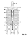
- Figuren 2a - 2c
- das erfindungsgemäße Setzverfahren für diesen Dübel in drei Schnittdarstellungen; und
- Figur 3
- eine Detail-Schnittdarstellung, die den Eingriff des Setzwerkzeugs in den Halteteller des erfindungsgemäßen Dübels zeigt.
- Der in
Figur 1 dargestellte Dübel 1 weist eine lang gestreckte Dübelhülse 2 mit einem sich entlang der Längsachse erstreckenden Kanal 3 auf. Vorne weist die Dübelhülse 2 einen Spreizabschnitt 4 auf, an den sich ein Schaftabschnitt 5 anschließt. "Vorne" und "hinten" beziehen sich stets auf die Einbringrichtung E des Dübels beim Setzen. Der Übergang vom Schaftabschnitt 5 zum Spreizabschnitt 4 ist durch eine signifikante Verengung des Kanals 3 auf etwa die Hälfte des Durchmessers gekennzeichnet, während der Außendurchmesser im Wesentlichen nur sehr leicht konisch nach hinten erweitert. Im hinteren Viertel ist der Schaftabschnitt 4 nochmals um etwa 20 Prozent im Außendurchmesser erweitert. Der Spreizabschnitt 5 weist Kerben 6 derart auf, dass die Außenseite des Spreizabschnitts 5 eine widerhakenartige Struktur aufweist. Am hinteren Ende der Dübelhülse 2 erweitert sich der Schaftabschnitt 4 zu einem ersten Kragen 7 und es ist ein Halteteller 8 in diesem Bereich angeordnet. Der Halteteller 8 ist im Wesentlichen eine flache, kreisrunde Scheibe 9 mit mehreren, über den Umfang verteilten Ausnehmungen 10, sowie einen nach vorne ragenden, kurzen hülsenartigen Fortsatz 11 zur drehbaren Lagerung des Haltetellers 8 auf der Dübelhülse 2. Gegen eine Verschiebung nach hinten wird der Halteteller 8 vom ersten Kragen 7 gehalten, während er gegenüber einer Verschiebung nach vorne, die für das Setzen und den Einbauzustand nicht relevant ist, lediglich durch eine Rastverbindung 12 in Form einer umlaufenden Nut und eines umlaufenden Wulsts (nicht dargestellt) gehalten wird. Durch den Halt gegen Verschieben nach hinten ist der Halteteller 8 axialfest mit der Dübelhülse 2 im Sinne der Erfindung verbunden. Die Ausgestaltung der Verbindung als Rastverbindung 12 erlaubt, dass der Halteteller 8 gesondert von der Dübelhülse 2 bis zu einer Baustelle transportiert, dann erst vom Bediener von vorne her auf die Dübelhülse 2 geschoben und in der dargestellten Position verrastet wird. Hierdurch kann der Dübel 1 sehr platzsparend transportiert werden. Ganz unabhängig von den sonstigen Merkmalen des Ausführungsbeispiels kann die Rastverbindung 12 lösbar oder unlösbar gestaltet sein oder durch eine andere Art der Verbindung ersetzt sein. - Axial mittig liegt in der Dübelhülse 2 eine Schraube 13 als Spreizelement ein, wobei
Figur 1 den Zustand vor dem Setzen darstellt, bei dem das hintere Ende der Schraube 13 aus der Dübelhülse 2 herausschaut. Ohne die Schraube 13 ist der Dübel 1 so lang wie die Dübelhülse 2. Das vordere Ende der Schraube 13 wird von einem Metallstift 14 gebildet, der ein Gewinde 15 aufweist, dessen Länge etwa dem 1,5-fachen der Länge des Spreizabschnitts 5 der Dübelhülse 2 entspricht. Das Verhältnis der Gewindesteigung zum Gewindeaußendurchmesser liegt über den wesentlichen Teil der Länge bei 0,25, es handelt sich also um eine Schraube 13 geringer Steigung. An das Gewinde 15 schließt sich zunächst ein gewindeloser Abschnitt 16 und dann ein Kopfabschnitt 17 mit Rändel (nicht dargestellt) an. Der Kopfabschnitt 17 ist umspritzt mit Kunststoff, wodurch ein langgestreckter, im Wesentlichen zylindrischer Kopf 18 der Schraube 13 gebildet ist. Die Länge des Kopfes 18 entspricht im Wesentlichen der Länge des Spreizabschnitts 5. Im vorderen Bereich weist der Kopf 18 mehrere umlaufende erste Wülste 19 auf, die in Verbindung mit einem radial nach innen stehenden, umlaufenden zweiten Wulst 20 am hinteren Ende der Dübelhülse 2 dafür sorgen, dass die Schraube 13 in der dargestellten Position gegenüber der Dübelhülse 2 für das Setzen gehalten wird. Am hinteren Ende weist die Schraube 13 einen zweiten Kragen 21 auf, der beim Eintreiben der Schraube 13 in die Dübelhülse 2 im Bereich des ersten Kragens 7 der Dübelhülse 2 axial zum Anschlag kommt. Bei diesem Eintreiben gelangt die Schraube 13 mit ihrem Gewinde 15 in den Spreizabschnitt 5 der Dübelhülse 2. Damit sie dort greifen und zu einer Verspreizung führen kann, ist der Kanal 3 gegenüber dem Schaftabschnitt 4 deutlich verengt. Wie im Weiteren noch näher erläutert wird, ist der Eintreibvorgang der Schraube 13 in die Dübelhülse 2 nicht mit dem axialen Anschlagen des zweiten Kragens 21 an der Dübelhülse 2 beendet, sondern es soll eine Verkürzung der Dübelhülse 2 erfolgen. Hierzu weist die Dübelhülse 2 im vorderen, unmittelbar an den Spreizabschnitt 4 anschließenden Teil des Schaftabschnitts 5 eine Verkürzungszone 22 auf. Diese Verkürzungszone 22 wird durch mehrere lokale Schwächungen 23 gebildet, die die Dübelhülse 2 teilweise vollständig durchdringen, teilweise aber auch nur taschenartig ausgebildet sind. Dabei kommt es nicht darauf an, ob das Durchdringen teilweise oder vollständig erfolgt. Wichtig ist, dass die Dübelhülse 2 beim Transport und beim Einführen in ein Bohrloch in diesem Bereich nicht wesentlich deformiert wird, aber beim Eintreiben der Schraube 13 mittels eines möglichst geringen Drehmoments verkürzbar ist, wobei die Verkürzung im Ausführungsbeispiel durch eine plastische Stauchung erfolgt. - Anhand der
Figuren 2a - 2c wird im Folgenden das erfindungsgemäße Setzverfahren erläutert. Dieses Setzverfahren dient der Erstellung einer Befestigungsanordnung 24 mit einem plattenförmigen Dämmstoff 25, der mittels des Dübels 1 an einem Untergrund 26, hier ein Mauerwerk aus Hochlochziegeln, befestigt ist. Das Setzen erfolgt mittels eines Setzwerkzeugs 27, das beispielsweise in eine Bohrmaschine oder einen Akkuschrauber (nicht dargestellt) eingespannt werden kann. - Das Setzwerkzeug 27 weist einen zylindrischen Grundkörper 28 auf, von dem an einer dem Dübel 1 zugewandten, vorderen Seite mehrere axial nach vorne ragende, längliche zylindrische Zapfen 29 als Vorsprünge 30 angeordnet sind. Insgesamt sind sieben Zapfen 29 über den Umfang verteilt auf einer gedachten Kreislinie angeordnet. Außerdem ragt vom Grundkörper 28 entlang des Umfangs ein umlaufender Rand 31 nach vorne, wobei der Rand 31 nicht ganz so weit nach vorne ragt wie die Zapfen 29. An der gegenüberliegenden, hinteren Seite des Grundkörpers 28 wird dieser von einem Anschlagsteller 32 in radialer Richtung überragt. In axialer Richtung schließt sich mittig an den Grundkörper 28 nach hinten ein sechskantiger Schaft 33 zur Aufnahme des Setzwerkzeugs 27 in einer Bohrmaschine oder dgl. an. Mittig nach vorne überragt den Grundkörper 28 in axialer Richtung außerdem ein sternförmiges Schraubbit 34.
- Zur Erstellung der Befestigungsanordnung 24 wird zunächst ein Bohrloch 35 durch den Dämmstoff 25 hindurch in den Untergrund 26 erstellt. In das Bohrloch 35 wird der Dübel 1 gesteckt, bis der Halteteller 8 an einer Außenseite 36 des Dämmstoffs 25 zur Anlage kommt. Der Spreizabschnitt 5 des Dübels 1 ist dabei im Bereich des Untergrunds 26 angeordnet. Vor oder nach dem Einstecken des Dübels 1 wird das Setzwerkzeug 27 mit dem Schraubbit 34 auf die Schraube 13 aufgesteckt, wozu diese eine sternförmige Werkzeugaufnahme 37 an ihrem hinteren Ende aufweist (siehe
Figur 1 ). Durch Drehung des Setzwerkzeugs 27 wird die Schraube 13 in die Dübelhülse 2 eingetrieben und verspreizt den Spreizabschnitt 5, wodurch der Dübel 1 Halt im Untergrund 26 erhält. Das Eintreiben erfolgt in einem ersten Schritt bis zu dem inFigur 2b dargestellten Zustand, es wird also nur die Schraube 13 gedreht. Bei dem inFigur 2b dargestellten Übergang zum zweiten Schritt setzt einerseits der zweite Kragen 21 der Schraube 13 auf der Dübelhülse 2 auf, und es greifen andererseits die Zapfen 29 formschlüssig in die Ausnehmungen 10 des Haltetellers 8 ein. Beides muss nicht zwingend genau gleichzeitig erfolgen, sondern kann auch in einer längeren Übergangszeit nacheinander geschehen. Auch braucht die Drehbewegung nicht gestoppt werden, sondern der Bediener kann das Setzwerkzeug 27 kontinuierlich bis zum Abschluss des Setzvorgangs (Figur 2c ) weiter drehen lassen. Das formschlüssige Eingreifen ist inFigur 3 im Detail dargestellt, da hier ein Schnitt durch einen der Zapfen 29 und die korrespondierende Ausnehmung 10 gezeigt ist. Die Ausnehmung 10 ist als eine in Umfangsrichtung verlaufende Nut 38 (sieheFiguren 1 und3 ) ausgebildet, die den Halteteller 8 axial durchsetzt. Da der Zapfen 29 zylindrisch ist, hat er innerhalb der Nut 38 Spiel in Umfangsrichtung. Dies ermöglicht, dass der Zapfen 29 entlang einer schraubenlinienförmigen Relativbewegung in die Nut 38 eingreifen kann, also insbesondere durch die beim Einschrauben der Schraube 13 bestehende Kombination aus translatorischer Bewegung in Achsrichtung und Rotation um die Längsachse L des Setzwerkzeugs 27. Die Relativbewegung ist durch die Schraubenlinie S angedeutet dargestellt. Beim Übergang vom ersten zum zweiten Schritt kann es vorkommen, dass der Zapfen 29 nicht exakt der Schraubenlinie S folgt, sondern beispielsweise zunächst zwischen zwei Nuten 38 aufsetzt. Dies führt jedoch lediglich dazu, dass der Zapfen 29 zunächst auf dem Halteteller 8 entlang gleitet und ihn dabei etwas in den Dämmstoff 25 drückt, um dann in die in Drehrichtung nächste Nut 38 einzugreifen. Auch bei relativ hoher Drehzahl kann es dabei durch die Länge der Nut 38 jedoch nicht dazu kommen, dass diese Nut 38 übersprungen wird. Somit gewährleistet die Kombination aus zylindrischem Zapfen 29 und in Umfangsrichtung verlaufender Nut 38 ein besonders zuverlässiges formschlüssiges Eingreifen mittels einer schraublinienförmigen Relativbewegung. - Durch weiteres Drehen des Setzwerkzeugs 27 wird im zweiten Schritt des Setzverfahrens sowohl die Schraube 13 als auch der Halteteller 8 gedreht. Da der zweite Kragen 21 der Schraube 13 wie beschrieben auf der Dübelhülse 2 aufliegt, erzeugt die weitere Drehbewegung axiale Schubkräfte innerhalb der Dübelhülse 2, die zum plastischen Stauchen der Verkürzungszone 22 führen. Durch den axialen Halt des Haltetellers 8 an der Dübelhülse 2 wird der Halteteller 8 drehend in den Dämmstoff 25 gezogen, wobei er gleichzeitig an seinem äußeren Umfang axial durch den Rand 31 gestützt wird. Der Halteteller 8 wird soweit in den Dämmstoff 25 versenkt, bis der Anschlagsteller 32 des Setzwerkzeugs 27 auf der Außenseite 36 des Dämmstoffs 25 aufsitzt, wie dies in
Figur 2c dargestellt ist. Abschließend wird das Setzwerkzeug 27 abgenommen und die im Dämmstoff 25 entstandene Vertiefung 39 kann mit einer Dämmstoffrondelle (nicht dargestellt) geschlossen werden. - Das beschriebene Setzverfahren mit dem Dübel 1 und dem Setzwerkzeug 27 ermöglicht einerseits eine platzsparende Verpackung des Dübels 1 und andererseits ein zuverlässiges, schnelles Setzen.
-
- 1
- Dübel
- 2
- Dübelhülse
- 3
- Kanal
- 4
- Schaftabschnitt
- 5
- Spreizabschnitt
- 6
- Kerbe
- 7
- erster Kragen an der Dübelhülse 2
- 8
- Halteteller
- 9
- Scheibe
- 10
- Ausnehmung des Haltetellers 8
- 11
- Fortsatz
- 12
- Rastverbindung
- 13
- Schraube
- 14
- Metallstift
- 15
- Gewinde
- 16
- gewindeloser Abschnitt der Schraube 13
- 17
- Kopfabschnitt des Metallstifts 14
- 18
- Kopf der Schraube 13
- 19
- erster Wulst an der Schraube 13
- 20
- zweiter Wulst an der Dübelhülse 2
- 21
- zweiter Kragen an der Schraube 13
- 22
- Verkürzungszone
- 23
- Schwächung
- 24
- Befestigungsanordnung
- 25
- Dämmstoff
- 26
- Untergrund
- 27
- Setzwerkzeug
- 28
- Grundkörper
- 29
- Zapfen
- 30
- Vorsprung
- 31
- Rand
- 32
- Anschlagsteller
- 33
- Schaft
- 34
- Schraubbit
- 35
- Bohrloch
- 36
- Außenseite des Dämmstoffs 25
- 37
- Werkzeugaufnahme der Schraube 13
- 38
- Nut
- 39
- Vertiefung im Dämmstoff 25
- E
- Einbringrichtung
- L
- Längsachse des Setzwerkezeugs
- S
- Schraubenlinie
Claims (4)
- Kombination eines Dübels (1) und eines Setzwerkzeugs (27) zur Befestigung von Dämmstoffen (25),- wobei der Dübel (1) eine Schraube (13) als Spreizelement, eine Dübelhülse (2) und einen gegenüber der Dübelhülse (2) drehbaren Halteteller (8) aufweist,- und wobei das Setzwerkzeug (27) und der Dübel (1) derart gestaltet sind, dass das Setzwerkzeug (27) formschlüssig mit der Schraube (13) und mit dem Halteteller (8) in Eingriff gebracht werden kann,
dadurch gekennzeichnet, dass das Setzwerkzeug (27) und der Halteteller (8) derart gestaltet sind, dass das Setzwerkzeug (27) und der Halteteller (8) mittels einer schraublinienförmigen Relativbewegung miteinander in formschlüssigen Eingriff bringbar sind. - Kombination nach Anspruch 1, dadurch gekennzeichnet, dass das Setzwerkzeug (27) mindestens einen Vorsprung (30) aufweist, der formschlüssig in eine Ausnehmung (10) des Haltetellers (8) eingreift, oder dass der Halteteller (8) mindestens einen Vorsprung aufweist, der formschlüssig in eine Ausnehmung oder in einen Vorsprung des Setzwerkzeugs (27) eingreift.
- Kombination nach Anspruch 1, dadurch gekennzeichnet, dass das Setzwerkzeug (27) einen länglichen, insbesondere zylindrischen, Zapfen (29) als Vorsprung (30) und der Halteteller (8) eine in Umfangsrichtung verlaufende Nut (38) als Ausnehmung (10) aufweist.
- Setzverfahren zum Befestigen eines Dämmstoffs (25) an einem Untergrund (26), mit einem Dübel (1) und einem Setzwerkzeug (27), insbesondere nach einem der vorstehenden Ansprüche,- wobei der Dübel (1) eine Schraube (13) als Spreizelement, eine Dübelhülse (2) und einem Halteteller (8) aufweist,- wobei die Schraube (13) vom Setzwerkzeug (27) drehend in die Dübelhülse (2) eingetrieben wird, und- wobei dabei in einem ersten Schritt nur die Schraube (13) und dann in einem zweiten Schritt Schraube (13) und Halteteller (8) gemeinsam gedreht werden, dadurch gekennzeichnet, dass beim Übergang vom ersten zum zweiten Schritt das Setzwerkzeug (27) und der Halteteller (8) mittels einer schraublinienförmigen Relativbewegung miteinander in formschlüssigen Eingriff gebracht werden.
Applications Claiming Priority (1)
| Application Number | Priority Date | Filing Date | Title |
|---|---|---|---|
| DE102014101493.6A DE102014101493A1 (de) | 2014-02-06 | 2014-02-06 | Dübel, Setzwerkzeug und Verfahren zur Befestigung von Dämmstoffen |
Publications (3)
| Publication Number | Publication Date |
|---|---|
| EP2905391A1 true EP2905391A1 (de) | 2015-08-12 |
| EP2905391C0 EP2905391C0 (de) | 2023-06-07 |
| EP2905391B1 EP2905391B1 (de) | 2023-06-07 |
Family
ID=52394875
Family Applications (1)
| Application Number | Title | Priority Date | Filing Date |
|---|---|---|---|
| EP15000114.7A Active EP2905391B1 (de) | 2014-02-06 | 2015-01-16 | Kombination eines Dübels und eines Setzwerkzeugs bzw. Verfahren zur Befestigung von Dämmstoffen |
Country Status (5)
| Country | Link |
|---|---|
| EP (1) | EP2905391B1 (de) |
| CN (1) | CN104832516A (de) |
| DE (1) | DE102014101493A1 (de) |
| PL (1) | PL2905391T3 (de) |
| RU (1) | RU2663098C2 (de) |
Families Citing this family (2)
| Publication number | Priority date | Publication date | Assignee | Title |
|---|---|---|---|---|
| DE102018102039A1 (de) | 2018-01-30 | 2019-08-01 | Fischerwerke Gmbh & Co. Kg | Befestigungssystem und Dämmstoffbefestiger |
| RU2676353C1 (ru) * | 2018-02-19 | 2018-12-28 | Роман Николаевич Чернухин | Способ крепления дюбеля |
Citations (3)
| Publication number | Priority date | Publication date | Assignee | Title |
|---|---|---|---|---|
| EP0921251A2 (de) * | 1997-12-08 | 1999-06-09 | Fischerwerke Arthur Fischer GmbH & Co. KG | Werkzeug zur Montage von Dämmstoffhaltern zur Dachbahnbefestigung |
| EP1318250A2 (de) | 2001-12-05 | 2003-06-11 | EJOT Kunststofftechnik GmbH & Co. KG | Dübel und Verfahren zur Montage von Dämmstoffplatten |
| EP2042666A2 (de) * | 2007-09-27 | 2009-04-01 | EJOT Baubefestigungen GmbH | Befestigungselement und Verfahren zur vertieften Montage einer Dämmstoffplatte |
Family Cites Families (5)
| Publication number | Priority date | Publication date | Assignee | Title |
|---|---|---|---|---|
| DK123950B (da) * | 1969-06-12 | 1972-08-21 | L Mortensen | Fastgørelsesorgan, der er beregnet til at blive monteret tværs gennem en mur eller plade. |
| DE102004006936A1 (de) * | 2004-02-12 | 2005-09-01 | Friedr. Trurnit Gmbh | Werkzeug zum Einbringen von Dämmstoffschrauben mit daran vorgesehenem Druckteller in eine Dämmstoffplatte oder dergleichen |
| DE102006006164A1 (de) * | 2006-02-10 | 2007-08-23 | Ranit-Befestigungssysteme Gmbh | Befestigungssystem für Bauteile an einen tragenden Untergrund sowie Verfahren und Montagehilfe zur Anbringung des Befestigungssystems |
| DE102008044124A1 (de) * | 2008-11-27 | 2010-06-02 | Hilti Aktiengesellschaft | Setzwerkzeug für einen Dämmstoffdübel |
| CZ303125B6 (cs) * | 2009-07-31 | 2012-04-18 | Bravoll Spol. S R. O. | Hmoždinka s alternativním zapuštením prítlacného talíre v izolaci a zpusob montáže a montážní prípravek |
-
2014
- 2014-02-06 DE DE102014101493.6A patent/DE102014101493A1/de active Pending
-
2015
- 2015-01-16 PL PL15000114.7T patent/PL2905391T3/pl unknown
- 2015-01-16 EP EP15000114.7A patent/EP2905391B1/de active Active
- 2015-02-03 RU RU2015103535A patent/RU2663098C2/ru active
- 2015-02-06 CN CN201510062752.5A patent/CN104832516A/zh active Pending
Patent Citations (3)
| Publication number | Priority date | Publication date | Assignee | Title |
|---|---|---|---|---|
| EP0921251A2 (de) * | 1997-12-08 | 1999-06-09 | Fischerwerke Arthur Fischer GmbH & Co. KG | Werkzeug zur Montage von Dämmstoffhaltern zur Dachbahnbefestigung |
| EP1318250A2 (de) | 2001-12-05 | 2003-06-11 | EJOT Kunststofftechnik GmbH & Co. KG | Dübel und Verfahren zur Montage von Dämmstoffplatten |
| EP2042666A2 (de) * | 2007-09-27 | 2009-04-01 | EJOT Baubefestigungen GmbH | Befestigungselement und Verfahren zur vertieften Montage einer Dämmstoffplatte |
Also Published As
| Publication number | Publication date |
|---|---|
| EP2905391C0 (de) | 2023-06-07 |
| DE102014101493A1 (de) | 2015-08-06 |
| RU2015103535A3 (de) | 2018-05-29 |
| EP2905391B1 (de) | 2023-06-07 |
| RU2663098C2 (ru) | 2018-08-01 |
| PL2905391T3 (pl) | 2023-10-16 |
| CN104832516A (zh) | 2015-08-12 |
| RU2015103535A (ru) | 2016-08-20 |
Similar Documents
| Publication | Publication Date | Title |
|---|---|---|
| EP1426633B1 (de) | Befestigungssystem | |
| EP2191938B1 (de) | Setzwerkzeug für einen Dämmstoffdübel | |
| EP2213888A2 (de) | Dämmstoffhalter | |
| DE102007000235A1 (de) | Setzwerkzeug für einen Dämmstoffdübel | |
| EP2466025B1 (de) | Dämmstoffhalter | |
| EP2905392B1 (de) | Setzverfahren zur befestigung von dämmstoffen | |
| EP3318685B1 (de) | Justagedübel | |
| EP3577350B1 (de) | Gipskartonplattendübel | |
| DE102011002637A1 (de) | Schraubanker und Verfahren zur Herstellung eines Schraubankers | |
| EP2224143B1 (de) | Mutter, Schraubverbindung, Profilverbindung sowie Verfahren zum Herstellen einer Mutter | |
| EP0521490A2 (de) | Anordnung aus zwei teleskopisch miteinander verbundenen Bauelementen | |
| DE19642914C2 (de) | Dübel | |
| WO2009103391A1 (de) | Befestigungselement für holzfaserdämmplatten | |
| EP2613061A2 (de) | Verschlusseinrichtung zum Verschließen einer hydraulischen und/oder pneumatischen Bohrung | |
| EP1582684B1 (de) | Schraube zur Verankerung eines mit einem Metallprofil verstärkten Kunststoffhohlprofils an einem Unterbau | |
| DE69934409T2 (de) | Werkzeug und verfahren zum abscheren von bolzen | |
| EP2905391B1 (de) | Kombination eines Dübels und eines Setzwerkzeugs bzw. Verfahren zur Befestigung von Dämmstoffen | |
| DE102014224561B3 (de) | Spannfutter | |
| EP2930378A1 (de) | Distanzbefestigungselement | |
| DE102008001552A1 (de) | Befestigungsanordnung | |
| EP3135927B1 (de) | Schraube zum einschrauben in ein bohrloch und anordnung mit einer derartigen schraube | |
| EP2682543A2 (de) | Beschlaganordnung | |
| EP4069986B1 (de) | Buchse mit freigestelltem gewindeabschnitt zur aufnahme eines befestigungselements | |
| DE102013103429A1 (de) | Dämmstoffhalter | |
| EP2786840A2 (de) | Setzgerät und dessen Kombination mit einem Befestigungselement |
Legal Events
| Date | Code | Title | Description |
|---|---|---|---|
| PUAI | Public reference made under article 153(3) epc to a published international application that has entered the european phase |
Free format text: ORIGINAL CODE: 0009012 |
|
| AK | Designated contracting states |
Kind code of ref document: A1 Designated state(s): AL AT BE BG CH CY CZ DE DK EE ES FI FR GB GR HR HU IE IS IT LI LT LU LV MC MK MT NL NO PL PT RO RS SE SI SK SM TR |
|
| AX | Request for extension of the european patent |
Extension state: BA ME |
|
| 17P | Request for examination filed |
Effective date: 20160128 |
|
| RBV | Designated contracting states (corrected) |
Designated state(s): AL AT BE BG CH CY CZ DE DK EE ES FI FR GB GR HR HU IE IS IT LI LT LU LV MC MK MT NL NO PL PT RO RS SE SI SK SM TR |
|
| GRAP | Despatch of communication of intention to grant a patent |
Free format text: ORIGINAL CODE: EPIDOSNIGR1 |
|
| RIC1 | Information provided on ipc code assigned before grant |
Ipc: E04B 1/76 20060101AFI20160331BHEP |
|
| INTG | Intention to grant announced |
Effective date: 20160413 |
|
| TPAC | Observations filed by third parties |
Free format text: ORIGINAL CODE: EPIDOSNTIPA |
|
| GRAS | Grant fee paid |
Free format text: ORIGINAL CODE: EPIDOSNIGR3 |
|
| GRAJ | Information related to disapproval of communication of intention to grant by the applicant or resumption of examination proceedings by the epo deleted |
Free format text: ORIGINAL CODE: EPIDOSDIGR1 |
|
| GRAL | Information related to payment of fee for publishing/printing deleted |
Free format text: ORIGINAL CODE: EPIDOSDIGR3 |
|
| INTC | Intention to grant announced (deleted) | ||
| 17Q | First examination report despatched |
Effective date: 20160826 |
|
| STAA | Information on the status of an ep patent application or granted ep patent |
Free format text: STATUS: EXAMINATION IS IN PROGRESS |
|
| TPAC | Observations filed by third parties |
Free format text: ORIGINAL CODE: EPIDOSNTIPA |
|
| GRAP | Despatch of communication of intention to grant a patent |
Free format text: ORIGINAL CODE: EPIDOSNIGR1 |
|
| STAA | Information on the status of an ep patent application or granted ep patent |
Free format text: STATUS: GRANT OF PATENT IS INTENDED |
|
| GRAJ | Information related to disapproval of communication of intention to grant by the applicant or resumption of examination proceedings by the epo deleted |
Free format text: ORIGINAL CODE: EPIDOSDIGR1 |
|
| STAA | Information on the status of an ep patent application or granted ep patent |
Free format text: STATUS: EXAMINATION IS IN PROGRESS |
|
| INTG | Intention to grant announced |
Effective date: 20220316 |
|
| RIN1 | Information on inventor provided before grant (corrected) |
Inventor name: RENZ, JUERGEN |
|
| INTC | Intention to grant announced (deleted) | ||
| RIN1 | Information on inventor provided before grant (corrected) |
Inventor name: RENZ, JUERGEN |
|
| GRAP | Despatch of communication of intention to grant a patent |
Free format text: ORIGINAL CODE: EPIDOSNIGR1 |
|
| STAA | Information on the status of an ep patent application or granted ep patent |
Free format text: STATUS: GRANT OF PATENT IS INTENDED |
|
| INTG | Intention to grant announced |
Effective date: 20221025 |
|
| GRAS | Grant fee paid |
Free format text: ORIGINAL CODE: EPIDOSNIGR3 |
|
| GRAA | (expected) grant |
Free format text: ORIGINAL CODE: 0009210 |
|
| STAA | Information on the status of an ep patent application or granted ep patent |
Free format text: STATUS: THE PATENT HAS BEEN GRANTED |
|
| AK | Designated contracting states |
Kind code of ref document: B1 Designated state(s): AL AT BE BG CH CY CZ DE DK EE ES FI FR GB GR HR HU IE IS IT LI LT LU LV MC MK MT NL NO PL PT RO RS SE SI SK SM TR |
|
| REG | Reference to a national code |
Ref country code: GB Ref legal event code: FG4D Free format text: NOT ENGLISH |
|
| REG | Reference to a national code |
Ref country code: CH Ref legal event code: EP Ref country code: AT Ref legal event code: REF Ref document number: 1575442 Country of ref document: AT Kind code of ref document: T Effective date: 20230615 |
|
| REG | Reference to a national code |
Ref country code: DE Ref legal event code: R096 Ref document number: 502015016379 Country of ref document: DE |
|
| U01 | Request for unitary effect filed |
Effective date: 20230607 |
|
| U07 | Unitary effect registered |
Designated state(s): AT BE BG DE DK EE FI FR IT LT LU LV MT NL PT SE SI Effective date: 20230614 |
|
| REG | Reference to a national code |
Ref country code: LT Ref legal event code: MG9D |
|
| PG25 | Lapsed in a contracting state [announced via postgrant information from national office to epo] |
Ref country code: NO Free format text: LAPSE BECAUSE OF FAILURE TO SUBMIT A TRANSLATION OF THE DESCRIPTION OR TO PAY THE FEE WITHIN THE PRESCRIBED TIME-LIMIT Effective date: 20230907 Ref country code: ES Free format text: LAPSE BECAUSE OF FAILURE TO SUBMIT A TRANSLATION OF THE DESCRIPTION OR TO PAY THE FEE WITHIN THE PRESCRIBED TIME-LIMIT Effective date: 20230607 |
|
| PG25 | Lapsed in a contracting state [announced via postgrant information from national office to epo] |
Ref country code: RS Free format text: LAPSE BECAUSE OF FAILURE TO SUBMIT A TRANSLATION OF THE DESCRIPTION OR TO PAY THE FEE WITHIN THE PRESCRIBED TIME-LIMIT Effective date: 20230607 Ref country code: HR Free format text: LAPSE BECAUSE OF FAILURE TO SUBMIT A TRANSLATION OF THE DESCRIPTION OR TO PAY THE FEE WITHIN THE PRESCRIBED TIME-LIMIT Effective date: 20230607 Ref country code: GR Free format text: LAPSE BECAUSE OF FAILURE TO SUBMIT A TRANSLATION OF THE DESCRIPTION OR TO PAY THE FEE WITHIN THE PRESCRIBED TIME-LIMIT Effective date: 20230908 |
|
| U20 | Renewal fee for the european patent with unitary effect paid |
Year of fee payment: 10 Effective date: 20231204 |
|
| PG25 | Lapsed in a contracting state [announced via postgrant information from national office to epo] |
Ref country code: SK Free format text: LAPSE BECAUSE OF FAILURE TO SUBMIT A TRANSLATION OF THE DESCRIPTION OR TO PAY THE FEE WITHIN THE PRESCRIBED TIME-LIMIT Effective date: 20230607 |
|
| PG25 | Lapsed in a contracting state [announced via postgrant information from national office to epo] |
Ref country code: IS Free format text: LAPSE BECAUSE OF FAILURE TO SUBMIT A TRANSLATION OF THE DESCRIPTION OR TO PAY THE FEE WITHIN THE PRESCRIBED TIME-LIMIT Effective date: 20231007 |
|
| PG25 | Lapsed in a contracting state [announced via postgrant information from national office to epo] |
Ref country code: SM Free format text: LAPSE BECAUSE OF FAILURE TO SUBMIT A TRANSLATION OF THE DESCRIPTION OR TO PAY THE FEE WITHIN THE PRESCRIBED TIME-LIMIT Effective date: 20230607 Ref country code: SK Free format text: LAPSE BECAUSE OF FAILURE TO SUBMIT A TRANSLATION OF THE DESCRIPTION OR TO PAY THE FEE WITHIN THE PRESCRIBED TIME-LIMIT Effective date: 20230607 Ref country code: RO Free format text: LAPSE BECAUSE OF FAILURE TO SUBMIT A TRANSLATION OF THE DESCRIPTION OR TO PAY THE FEE WITHIN THE PRESCRIBED TIME-LIMIT Effective date: 20230607 Ref country code: IS Free format text: LAPSE BECAUSE OF FAILURE TO SUBMIT A TRANSLATION OF THE DESCRIPTION OR TO PAY THE FEE WITHIN THE PRESCRIBED TIME-LIMIT Effective date: 20231007 |
|
| REG | Reference to a national code |
Ref country code: DE Ref legal event code: R097 Ref document number: 502015016379 Country of ref document: DE |
|
| PLBE | No opposition filed within time limit |
Free format text: ORIGINAL CODE: 0009261 |
|
| STAA | Information on the status of an ep patent application or granted ep patent |
Free format text: STATUS: NO OPPOSITION FILED WITHIN TIME LIMIT |
|
| 26N | No opposition filed |
Effective date: 20240308 |
|
| PG25 | Lapsed in a contracting state [announced via postgrant information from national office to epo] |
Ref country code: MC Free format text: LAPSE BECAUSE OF FAILURE TO SUBMIT A TRANSLATION OF THE DESCRIPTION OR TO PAY THE FEE WITHIN THE PRESCRIBED TIME-LIMIT Effective date: 20230607 |
|
| PG25 | Lapsed in a contracting state [announced via postgrant information from national office to epo] |
Ref country code: MC Free format text: LAPSE BECAUSE OF FAILURE TO SUBMIT A TRANSLATION OF THE DESCRIPTION OR TO PAY THE FEE WITHIN THE PRESCRIBED TIME-LIMIT Effective date: 20230607 |
|
| REG | Reference to a national code |
Ref country code: CH Ref legal event code: PL |
|
| GBPC | Gb: european patent ceased through non-payment of renewal fee |
Effective date: 20240116 |
|
| PG25 | Lapsed in a contracting state [announced via postgrant information from national office to epo] |
Ref country code: GB Free format text: LAPSE BECAUSE OF NON-PAYMENT OF DUE FEES Effective date: 20240116 |
|
| PG25 | Lapsed in a contracting state [announced via postgrant information from national office to epo] |
Ref country code: CH Free format text: LAPSE BECAUSE OF NON-PAYMENT OF DUE FEES Effective date: 20240131 |
|
| PG25 | Lapsed in a contracting state [announced via postgrant information from national office to epo] |
Ref country code: GB Free format text: LAPSE BECAUSE OF NON-PAYMENT OF DUE FEES Effective date: 20240116 Ref country code: CH Free format text: LAPSE BECAUSE OF NON-PAYMENT OF DUE FEES Effective date: 20240131 |
|
| PG25 | Lapsed in a contracting state [announced via postgrant information from national office to epo] |
Ref country code: IE Free format text: LAPSE BECAUSE OF NON-PAYMENT OF DUE FEES Effective date: 20240116 |
|
| PG25 | Lapsed in a contracting state [announced via postgrant information from national office to epo] |
Ref country code: IE Free format text: LAPSE BECAUSE OF NON-PAYMENT OF DUE FEES Effective date: 20240116 |
|
| U20 | Renewal fee for the european patent with unitary effect paid |
Year of fee payment: 11 Effective date: 20250101 |
|
| PG25 | Lapsed in a contracting state [announced via postgrant information from national office to epo] |
Ref country code: CY Free format text: LAPSE BECAUSE OF FAILURE TO SUBMIT A TRANSLATION OF THE DESCRIPTION OR TO PAY THE FEE WITHIN THE PRESCRIBED TIME-LIMIT; INVALID AB INITIO Effective date: 20150116 |
|
| PG25 | Lapsed in a contracting state [announced via postgrant information from national office to epo] |
Ref country code: HU Free format text: LAPSE BECAUSE OF FAILURE TO SUBMIT A TRANSLATION OF THE DESCRIPTION OR TO PAY THE FEE WITHIN THE PRESCRIBED TIME-LIMIT; INVALID AB INITIO Effective date: 20150116 |
|
| PG25 | Lapsed in a contracting state [announced via postgrant information from national office to epo] |
Ref country code: TR Free format text: LAPSE BECAUSE OF FAILURE TO SUBMIT A TRANSLATION OF THE DESCRIPTION OR TO PAY THE FEE WITHIN THE PRESCRIBED TIME-LIMIT Effective date: 20230607 |
|
| U20 | Renewal fee for the european patent with unitary effect paid |
Year of fee payment: 12 Effective date: 20260101 |
|
| PGFP | Annual fee paid to national office [announced via postgrant information from national office to epo] |
Ref country code: CZ Payment date: 20260114 Year of fee payment: 12 |
|
| PGFP | Annual fee paid to national office [announced via postgrant information from national office to epo] |
Ref country code: PL Payment date: 20260108 Year of fee payment: 12 |