EP2905232A1 - Sealing tool top of a tray closing machine and corresponding method - Google Patents
Sealing tool top of a tray closing machine and corresponding method Download PDFInfo
- Publication number
- EP2905232A1 EP2905232A1 EP14154596.2A EP14154596A EP2905232A1 EP 2905232 A1 EP2905232 A1 EP 2905232A1 EP 14154596 A EP14154596 A EP 14154596A EP 2905232 A1 EP2905232 A1 EP 2905232A1
- Authority
- EP
- European Patent Office
- Prior art keywords
- dome
- film
- sealing tool
- sealing
- vacuum
- Prior art date
- Legal status (The legal status is an assumption and is not a legal conclusion. Google has not performed a legal analysis and makes no representation as to the accuracy of the status listed.)
- Withdrawn
Links
Images


Classifications
-
- B—PERFORMING OPERATIONS; TRANSPORTING
- B65—CONVEYING; PACKING; STORING; HANDLING THIN OR FILAMENTARY MATERIAL
- B65B—MACHINES, APPARATUS OR DEVICES FOR, OR METHODS OF, PACKAGING ARTICLES OR MATERIALS; UNPACKING
- B65B31/00—Packaging articles or materials under special atmospheric or gaseous conditions; Adding propellants to aerosol containers
- B65B31/02—Filling, closing, or filling and closing, containers or wrappers in chambers maintained under vacuum or superatmospheric pressure or containing a special atmosphere, e.g. of inert gas
- B65B31/025—Filling, closing, or filling and closing, containers or wrappers in chambers maintained under vacuum or superatmospheric pressure or containing a special atmosphere, e.g. of inert gas specially adapted for rigid or semi-rigid containers
- B65B31/028—Filling, closing, or filling and closing, containers or wrappers in chambers maintained under vacuum or superatmospheric pressure or containing a special atmosphere, e.g. of inert gas specially adapted for rigid or semi-rigid containers closed by a lid sealed to the upper rim of the container, e.g. tray-like container
-
- B—PERFORMING OPERATIONS; TRANSPORTING
- B65—CONVEYING; PACKING; STORING; HANDLING THIN OR FILAMENTARY MATERIAL
- B65B—MACHINES, APPARATUS OR DEVICES FOR, OR METHODS OF, PACKAGING ARTICLES OR MATERIALS; UNPACKING
- B65B7/00—Closing containers or receptacles after filling
- B65B7/16—Closing semi-rigid or rigid containers or receptacles not deformed by, or not taking-up shape of, contents, e.g. boxes or cartons
- B65B7/162—Closing semi-rigid or rigid containers or receptacles not deformed by, or not taking-up shape of, contents, e.g. boxes or cartons by feeding web material to securing means
- B65B7/164—Securing by heat-sealing
Definitions
- the object of the present invention is to constructively simplify a tray sealing machine for packaging trays which have products that contain the edge of the tray.
- At least one depression around a dome or around all domes is provided at least partially, preferably closed, circumferentially.
- the lidding foil can be held on all four sides around the dome or domes even during the molding process.
- the cover film is thereby deep-drawn or formed at least partially into the depression.
- the settable under vacuum recess thus generates a high holding torque in addition to the static friction of the lid film on the underside of the sealing tool shell.
- the depression is a U-shaped or V-shaped groove, since it is easy to manufacture and suitable for deep-drawing or shaping the cover film into this groove.
- Under a U-shaped groove is also a rectangular shape, as used for inserting sealing cords to understand.
- the recess comprises a dome-oriented edge for vacuum-forming the lid film around the edge. This creates a very high holding force and counteracts the tensile force through the lid film when molding in the dome.
- the edge at an angle of at least 70 °, preferably 90 °.
- At least one or each recess preferably has a width of 1 mm to 5 mm and / or a depth of 0.5 mm to 3 mm.
- the heating plate is preferably provided on the underside of the sealing tool upper part upstream of a production direction of the cover film in order to have the shortest possible transport path for the cover film from the heating position to the molding position and thus to achieve a very short time span, during which the cover film cools before the molding process.
- a method for operating a tray sealing machine with a sealing tool upper part comprising at least one dome to form a lid film in the dome is characterized in that before and during the molding of the lid film into the dome (or dome) one outside of Domes or the dome arranged film holding device on the underside of the sealing tool upper part holds the lid film by means of vacuum.
- the molding process can take place independently of time of transport of the shell and for holding the lid film on the sealing tool shell no clamping frame or sealing tool base is needed. Or the molding takes place by lifting the shell with protruding product therein to the lidding film.
- the product forms the lid foil into the dome.
- the phrase "forming the lid foil in the dome” does not necessarily require that the lid foil be applied to the entire surface of the dome. Rather, it is sufficient if the lid foil deforms into the interior of the dome.
- the cover sheet is formed around an edge of the recess in order to further increase the holding force.
- the cover film is preferably heated by means of a heating plate before the heated part of the cover film is transported under the dome of the sealing tool upper part.
- the lidding film is heated to the extent that a plastic deformation during molding in the dome is made possible and in skin films shrinkback and thus a flat concern to the product is possible.
- FIG. 1 shows a tray sealing machine 1 with a sealing station 2, the shells 20 sealed with a lid film 3, and a gripper system 4, which moves the trays 20 in a transport direction P from a feed conveyor 19 in the sealing station 2.
- the sealing station 2 has a sealing tool lower part 5 and a sealing tool upper part 6 arranged above it.
- the cover film 3 is transported intermittently in the production direction P.
- the stationary lidding film 3 is pulled over the film holding device 9 by means of a vacuum to the underside 10 of the sealing tool upper part 6 and thus the lidding film 3 also bears against the heating plate 7.
- the voltage applied to the heating plate 7 part of the lid film 3 is heated to the desired or predetermined temperature.
- the film holding device 9 is deactivated by venting the vacuum openings 12 and the lid film 3 and thus the heated part of the lid film 3 in the production direction P are transported under the dome 8.
- the film holding device 9 is activated again and the lid film 3 is held.
- the lidding film 3 is cut according to the contour of the tray edge 22 and then moves the finished packaging produced together with the tray holder and the sealing tool base 5 down and thus the sealing station 2 is opened.
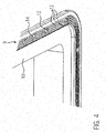
- FIG. 4 a detail view of the film holding device 9 is shown. It can clearly be seen that the film holding device 9 four recesses 13 which are parallel to each other, in the form of V-shaped grooves in the bottom 10 are provided. The required vacuum is provided via vacuum openings 12 for the individual recesses 13. In this case, the vacuum openings 13 are designed such that each individual vacuum opening 12 is connected to the adjacent recesses 13. To allow a compensation of the vacuum between parallel recesses 13, grooves 14 may be provided which are arranged transversely to the extension of the recesses 13 and establish a connection between the recesses 13.
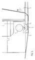
- FIG. 5 shows a detailed view as a sectional view of the film holding device 9 with the held under vacuum and molded into the dome 8 lid film 3.
- the lid film 3 is also partially formed in the recess 13.
- the lidding film 3 bears against an edge 15 oriented toward the dome 8.
- This deformation of the cover film 3 at the edge 15 produces a very high holding force of the cover film 3 on the film holding device 9 in order to counteract the tensile force F during the molding process and to hold the cover film 3 securely.
- the vacuum V Via the vacuum line 11, the vacuum V (see arrow) is generated at the recess 13.
- FIG. 6a shows a V-shaped groove as a recess 13 with the edge 15 in a sectional view.
- the Figures 6b and 6c show a U-shaped groove, the FIG. 6b an edge 15 with an angle ß of 90 °.
- the edge 15 of the FIG. 6c has an angle ß of about 75 ° and a groove base 16 is rounded, while the groove bottom 16 in FIG. 6b is rectangular.
- FIG. 6a also the width B and the depth T of the recess 13 are shown.
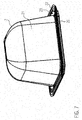
- FIG. 7 shows a shell 20 with a product 21, which projects far beyond a shell edge 22.
- the tray sealing machine 1 is particularly well suited to seal very high products 21, which are in very shallow bowls 20, with the lidding film 3.
- this can also be applied to the inner sides 23 of the shell 20.
- heating plate 7 is not integrated in the sealing tool upper part 6, but is provided as a separate workstation in front of the sealing tool upper part 6.
- a heating plate 7 is also optional provided, since very thin and flexible lidding sheets 3 do not require heating to be formed in the dome 8.
- the term “forms" is to be equated with the usual term "deep drawing”.
- the lidding film 3 is vacuum formed in the mandrel 8 before a sealing tool base 5 with a shell 20 in which a projecting over a shell edge product 21, with the sealing tool shell 6 forms a vacuum chamber to the interior of the shell 20 to evacuate and / or aerate and then seal the lid film 3 with the shell 20.
- the dome 8 may also be heated to reheat the lidding film 3 so that it can rest tightly against the product 21 after venting.
Abstract
Die Erfindung betrifft eine Schalenverschließmaschine (1) mit einem Siegelwerkzeugoberteil (6), das eine Folienhalteeinrichtung (9) aufweist, um eine Deckelfolie (3) zu halten, während die Deckelfolie (3) in Dome (8) im Siegelwerkzeugoberteil (6) geformt wird.The invention relates to a tray sealing machine (1) having a sealing tool upper part (6) which has a film holding device (9) for holding a lid film (3) while the lid film (3) is formed in domes (8) in the sealing tool top part (6) ,
Description
Die Erfindung bezieht sich auf eine Schalenverschließmaschine gemäß dem Oberbegriff des Anspruchs 1 bzw. auf ein Verfahren mit den Merkmalen des Anspruchs 11.The invention relates to a tray sealing machine according to the preamble of claim 1 or to a method having the features of
Es ist aus der
Aufgabe der vorliegenden Erfindung ist es, eine Schalenverschließmaschine zum Verpacken von Schalen, die über den Schalenrand beinhaltende Produkte aufweisen, konstruktiv zu vereinfachen.The object of the present invention is to constructively simplify a tray sealing machine for packaging trays which have products that contain the edge of the tray.
Diese Aufgabe wird gelöst durch eine Schalenverschließmaschine mit den Merkmalen des Anspruchs 1 bzw. durch ein Verfahren zum Betrieb einer solchen Schalenverschließmaschine mit den Merkmalen des Anspruchs 11. Vorteilhafte Weiterbildungen der Erfindung sind in den Unteransprüchen angegeben.This object is achieved by a tray sealing machine with the features of claim 1 or by a method for operating such a tray sealing machine with the features of
Die erfindungsgemäße Schalenverschließmaschine umfasst ein Siegelwerkzeugoberteil zum Formen einer Deckelfolie in wenigstens einen Dom im Siegelwerkzeugoberteil und zum Siegeln der Deckelfolie an eine Schale. Die Schalenverschließmaschine zeichnet sich dadurch aus, dass an der Unterseite des Siegelwerkzeugoberteils außerhalb des Doms oder der Dome eine Folienhaltevorrichtung vorgesehen ist, die wenigstens eine Vertiefung aufweist, wobei die Vertiefung dazu konfiguriert ist, mittels Vakuum die Deckelfolie an die Unterseite anzusaugen. Dabei sind in der oder den Vertiefungen Vakuumöffnungen zum Erzeugen des Vakuums vorgesehen. Dies ermöglicht ein Formen der Deckelfolie in den Dom des Siegelwerkzeugunterteils, ohne dass ein Klemmrahmen zum Halten der Deckelfolie an der Unterseite des Siegelwerkzeugoberteils benötigt wird, da die Deckelfolie mittels einer oder mehrerer Vertiefungen unter Vakuum angesaugt und somit gehalten wird. Ein Siegelwerkzeugunterteil bzw. eine Schalenaufnahme mit der oder den Schalen, die über einen Schalenrand und damit auch über das Siegelwerkzeugunterteil bzw. über die Schalenaufnahme überstehende Produkte aufgenommen haben, kann in einer Warteposition beabstandet zum Siegelwerkzeugoberteil verbleiben, bis das Formen der Deckelfolie in den Dom erfolgt ist. Ein weiterer Vorteil ist, dass das Formen der Deckelfolie zeitlich unabhängig zum Transport der Schalen in bzw. auf das Siegelwerkzeugunterteil ablaufen kann und somit die Leistung der Schalenverschließmaschine zum Verpacken von über die Schale überstehenden Produkten gesteigert werden kann. Es ist auch denkbar, dass die Deckelfolie nicht in den Dom mittels Vakuum im Dom verformt wird, sondern dass die Deckelfolie einfach durch das Produkt beim Anheben der Schale in den Dom verformt wird.The tray sealing machine according to the invention comprises a sealing tool upper part for forming a cover film in at least one dome in the sealing tool upper part and for sealing the cover film to a shell. The tray sealing machine is characterized in that on the underside of the sealing tool upper part outside the dome or the dome, a film holding device is provided which has at least one recess, wherein the recess is configured to vacuum suck the lid film to the underside. In this case, vacuum openings for generating the vacuum are provided in the recess or cavities. This allows the cover sheet to be molded into the dome of the sealing die bottom without the need of a clamping frame for holding the lid sheet on the underside of the sealing tool top as the lid sheet is vacuum drawn and thus held by one or more recesses. A sealing tool base or a shell receptacle with the or the shells, which have received over a shell edge and thus also on the sealing tool base or on the shell receptacle protruding products, may remain in a waiting position spaced from the sealing tool shell until the forming of the lid film is done in the dome. Another advantage is that the forming of the lidding film can proceed independently of time for transporting the trays into or onto the sealing die bottom part, and thus the performance of the tray sealing machine for packaging products projecting beyond the dish can be increased. It is also conceivable that the lid film is not deformed into the dome by means of vacuum in the dome, but that the lid film is easily deformed by the product when lifting the shell in the dome.
Vorzugsweise ist wenigstens eine Vertiefung um einen Dom oder um alle Dome wenigstens teilweise, vorzugsweise geschlossen, umlaufend vorgesehen. So kann die Deckelfolie an allen vier Seiten um den Dom oder die Dome auch während des Formenvorgangs gehalten werden. Die Deckelfolie wird dabei wenigstens teilweise in die Vertiefung tiefgezogen bzw. geformt. Die unter Vakuum setzbare Vertiefung erzeugt damit ein hohes Haltemoment zusätzlich zur Haftreibung der Deckelfolie an der Unterseite des Siegelwerkzeugoberteils.Preferably, at least one depression around a dome or around all domes is provided at least partially, preferably closed, circumferentially. Thus, the lidding foil can be held on all four sides around the dome or domes even during the molding process. The cover film is thereby deep-drawn or formed at least partially into the depression. The settable under vacuum recess thus generates a high holding torque in addition to the static friction of the lid film on the underside of the sealing tool shell.
In einer vorteilhaften Ausführung ist die Vertiefung eine U- oder V-förmige Nut, da diese einfach herzustellen und geeignet ist, die Deckelfolie in diese Nut tiefzuziehen bzw. zu formen. Unter einer U-förmigen Nut ist auch eine Rechteckform, wie sie zum Einlegen von Dichtschnüren eingesetzt wird, zu verstehen.In an advantageous embodiment, the depression is a U-shaped or V-shaped groove, since it is easy to manufacture and suitable for deep-drawing or shaping the cover film into this groove. Under a U-shaped groove is also a rectangular shape, as used for inserting sealing cords to understand.
Vorzugsweise umfasst die Vertiefung eine zum Dom orientierte Kante, um die Deckelfolie um die Kante mittels Vakuum zu formen. Dies erzeugt eine sehr hohe Haltekraft und wirkt der Zugkraft durch die Deckelfolie beim Formen in den Dom entgegen.Preferably, the recess comprises a dome-oriented edge for vacuum-forming the lid film around the edge. This creates a very high holding force and counteracts the tensile force through the lid film when molding in the dome.
Dabei weist die Kante einen Winkel von wenigstens 70°, vorzugsweise 90° auf. Je größer der Winkel ist, desto höher ist die Haltekraft.In this case, the edge at an angle of at least 70 °, preferably 90 °. The larger the angle, the higher the holding force.
Vorzugsweise weist die Folienhaltevorrichtung mehrere parallel zueinander angeordnete Vertiefungen auf, um die Halterkraft weiter zu erhöhen.Preferably, the film holding device has a plurality of recesses arranged parallel to one another in order to further increase the holding force.
Mehrere oder alle Vertiefungen sind bevorzugt miteinander mittels quer zur Erstreckung der Vertiefungen vorgesehener Rillen miteinander verbunden, um einen Ausgleich des Vakuums zwischen den Vertiefungen zu ermöglichen. So kann auch die Anzahl von Vakuumöffnungen in den einzelnen Vertiefungen reduziert werden.Several or all recesses are preferably connected to each other by means provided transversely to the extension of the recesses grooves to compensate for To allow vacuums between the wells. Thus, the number of vacuum openings in the individual wells can be reduced.
Mindestens eine oder jede Vertiefung weist vorzugsweise eine Breite von 1 mm bis 5 mm und/oder eine Tiefe von 0,5 mm bis 3 mm auf.At least one or each recess preferably has a width of 1 mm to 5 mm and / or a depth of 0.5 mm to 3 mm.
Vorzugsweise ist eine Heizplatte zum Erwärmen der Deckelfolie vorgesehen, um das Formen der Deckelfolie in den Dom zu erleichtern und um bei Deckelfolien in Form von Skinfolien ein Rückschrumpfen nach dem Siegeln an die Schale zu erzeugen.Preferably, a heating plate is provided for heating the lidding film to facilitate forming the lidding film into the dome, and to produce shrinkback after lidding in the form of skin foils after sealing to the dish.
Dabei ist die Heizplatte bevorzugt an der Unterseite des Siegelwerkzeugoberteils stromaufwärts einer Produktionsrichtung der Deckelfolie vorgesehen, um eine möglichst kurze Transportstrecke für die Deckelfolie von der Heizposition zur Formposition zu haben und damit eine sehr geringe Zeitspanne zu erreichen, bei der die Deckelfolie vor dem Formprozess abkühlt.In this case, the heating plate is preferably provided on the underside of the sealing tool upper part upstream of a production direction of the cover film in order to have the shortest possible transport path for the cover film from the heating position to the molding position and thus to achieve a very short time span, during which the cover film cools before the molding process.
Ein erfindungsgemäßes Verfahren zum Betrieb einer Schalenverschließmaschine mit einem Siegelwerkzeugoberteil, das wenigstens einen Dom umfasst, um eine Deckelfolie in den Dom zu formen, zeichnet sich dadurch aus, dass vor und während des Formens der Deckelfolie in den Dom (oder die Dome) eine außerhalb des Doms oder der Dome angeordnete Folienhalteeinrichtung an der Unterseite des Siegelwerkzeugoberteils die Deckelfolie mittels Vakuum hält. So kann der Formprozess zeitlich unabhängig vom Transport der Schale erfolgen und zum Halten der Deckelfolie am Siegelwerkzeugoberteil wird kein Klemmrahmen oder Siegelwerkzeugunterteil benötigt. Oder das Formen findet durch das Anheben der Schale mit überstehendem Produkt darin an die Deckelfolie statt. Dabei formt das Produkt die Deckelfolie in den Dom hinein. Die Formulierung "Formen der Deckelfolie in den Dom" setzt nicht zwingend voraus, dass sich die Deckelfolie an der gesamten Fläche des Doms anlegt. Vielmehr genügt es, wenn sich die Deckelfolie in das Innere des Doms hinein verformt.A method according to the invention for operating a tray sealing machine with a sealing tool upper part comprising at least one dome to form a lid film in the dome is characterized in that before and during the molding of the lid film into the dome (or dome) one outside of Domes or the dome arranged film holding device on the underside of the sealing tool upper part holds the lid film by means of vacuum. Thus, the molding process can take place independently of time of transport of the shell and for holding the lid film on the sealing tool shell no clamping frame or sealing tool base is needed. Or the molding takes place by lifting the shell with protruding product therein to the lidding film. The product forms the lid foil into the dome. The phrase "forming the lid foil in the dome" does not necessarily require that the lid foil be applied to the entire surface of the dome. Rather, it is sufficient if the lid foil deforms into the interior of the dome.
Vorzugsweise wird die Deckelfolie mittels Vakuum in wenigstens eine Vertiefung der Folienhalteeinrichtung angesaugt, um eine hohe Haltekraft zu erzeugen.Preferably, the cover film is sucked by means of vacuum into at least one recess of the film holding device in order to produce a high holding force.
In einer besonders vorteilhaften Ausführung wird die Deckelfolie um eine Kante der Vertiefung geformt, um die Haltekraft weiter zu erhöhen.In a particularly advantageous embodiment, the cover sheet is formed around an edge of the recess in order to further increase the holding force.
Bevorzugt weist die Deckelfolie eine Stärke von 75 µm bis 200 µm auf.Preferably, the lidding film has a thickness of 75 .mu.m to 200 .mu.m.
Vorzugsweise wird die Deckelfolie mittels einer Heizplatte erwärmt, bevor der erwärmte Teil der Deckelfolie unter den Dom des Siegelwerkzeugoberteils transportiert wird. Dabei wird die Deckelfolie soweit erwärmt, dass eine plastische Verformung beim Formen in den Dom ermöglicht wird und bei Skinfolien ein Rückschrumpfen und somit ein flächiges Anliegen an das Produkt ermöglicht wird.The cover film is preferably heated by means of a heating plate before the heated part of the cover film is transported under the dome of the sealing tool upper part. In this case, the lidding film is heated to the extent that a plastic deformation during molding in the dome is made possible and in skin films shrinkback and thus a flat concern to the product is possible.
Im Folgenden wird ein vorteilhaftes Ausführungsbeispiel der Erfindung anhand einer Zeichnung näher erläutert. Im Einzelnen zeigen:
- Fig. 1
- eine erfindungsgemäße Schalenverschließmaschine,
- Fig. 2
- eine Seitenansicht des Siegelwerkzeugoberteils,
- Fig. 3
- eine Ansicht auf die Unterseite der Siegelwerkzeugoberteils,
- Fig. 4
- eine Detailansicht der Folienhalteeinrichtung von unten,
- Fig. 5
- eine seitliche Detailansicht der Folienhalteeinrichtung,
- Fig. 6a-c
- Ausführungsvarianten einer Vertiefung und
- Fig. 7
- eine Schale mit Produkt.
- Fig. 1
- a tray sealing machine according to the invention,
- Fig. 2
- a side view of the sealing tool shell,
- Fig. 3
- a view of the underside of the sealing tool shell,
- Fig. 4
- a detailed view of the film holding device from below,
- Fig. 5
- a side detail view of the film holding device,
- Fig. 6a-c
- Variants of a recess and
- Fig. 7
- a bowl of product.
Gleiche Komponenten sind in den Figuren durchgängig mit gleichen Bezugszeichen versehen.The same components are provided throughout the figures with the same reference numerals.
In
Im Folgenden soll das Verfahren zum Formen der Deckelfolie 3 näher erläutert werden. Die Deckelfolie 3 wird in Produktionsrichtung P intermittierend transportiert. Die stillstehende Deckelfolie 3 wird über die Folienhalteeinrichtung 9 mittels Vakuum an die Unterseite 10 des Siegelwerkzeugoberteils 6 gezogen und damit liegt die Deckelfolie 3 auch an der Heizplatte 7 an. Der an der Heizplatte 7 anliegende Teil der Deckelfolie 3 wird auf die gewünschte bzw. vorgegebene Temperatur erwärmt. Im nächsten Arbeitstakt wird die Folienhalteeinrichtung 9 durch Belüften der Vakuumöffnungen 12 deaktiviert und die Deckelfolie 3 werden und damit der erwärmte Teil der Deckelfolie 3 in Produktionsrichtung P unter die Dome 8 transportiert. Die Folienhalteeinrichtung 9 wird wieder aktiviert und die Deckelfolie 3 gehalten. Danach sorgt ein Vakuum im Inneren der Dome 8 oberhalb der Deckelfolie 3 für das Formen bzw. Tiefziehen der erwärmten Deckelfolie 3 in die Dome 8. Nach dem Formprozess folgt das nicht näher dargestellte Anheben der Schalen 20 mittels einer Schalenaufnahme von unten kommend an das Siegelwerkzeugoberteil 6 und das Schließen einer Kammer durch das Siegelwerkzeugunterteil 5, um das Innere der Schale 20 bzw. den Raum zwischen Schale 20 und Deckelfolie 3 zu evakuieren und/oder zu begasen. Nach dem Schließen der Kammer bzw. der Siegelstation 2 ist die Deckelfolie 3 von den Siegelwerkzeugen 5, 6 geklemmt und die Folienhalteeinrichtung 9 könnte deaktiviert werden. Es folgt das Siegeln der Deckelfolie 3 an die Schale 20 und ein Belüften der Dome 8. Dabei legt sich z. B. eine als Deckelfolie 3 verwendete Skinfolie flächig an das Produkt 21 und in die Innenseite 23 (siehe
In
Denkbar ist auch, dass die Heizplatte 7 nicht in dem Siegelwerkzeugoberteil 6 integriert ist, sondern als eigene Arbeitsstation vor dem Siegelwerkzeugoberteil 6 vorgesehen ist. Eine Heizplatte 7 ist auch nur optional vorgesehen, da sehr dünne und flexible Deckelfolien 3 keine Erwärmung benötigen, um in die Dome 8 geformt zu werden. Der Begriff "Formen" ist mit dem üblichen Begriff "Tiefziehen" gleichzusetzen.It is also conceivable that the heating plate 7 is not integrated in the sealing tool
Vorzugsweise wird die Deckelfolie 3 mittels Vakuum in den Dom 8 geformt wird, bevor ein Siegelwerkzeugunterteil 5 mit einer Schale 20, in der sich ein über einen Schalenrand überstehendes Produkt 21 befindet, mit dem Siegelwerkzeugoberteil 6 eine Vakuumkammer bildet, um das Innere der Schale 20 zu evakuieren und/oder zu begasen und anschließend die Deckelfolie 3 mit der Schale 20 zu versiegeln. Der Dom 8 kann auch beheizt sein, um die Deckelfolie 3 wieder zu erwärmen, damit sie sich nach dem Belüften eng an das Produkt 21 anlegen kann.Preferably, the
Claims (15)
Priority Applications (2)
| Application Number | Priority Date | Filing Date | Title |
|---|---|---|---|
| EP14154596.2A EP2905232A1 (en) | 2014-02-11 | 2014-02-11 | Sealing tool top of a tray closing machine and corresponding method |
| DE102014016833.6A DE102014016833A1 (en) | 2014-02-11 | 2014-11-14 | Sealing tool shell of a tray sealing machine |
Applications Claiming Priority (1)
| Application Number | Priority Date | Filing Date | Title |
|---|---|---|---|
| EP14154596.2A EP2905232A1 (en) | 2014-02-11 | 2014-02-11 | Sealing tool top of a tray closing machine and corresponding method |
Publications (1)
| Publication Number | Publication Date |
|---|---|
| EP2905232A1 true EP2905232A1 (en) | 2015-08-12 |
Family
ID=50072956
Family Applications (1)
| Application Number | Title | Priority Date | Filing Date |
|---|---|---|---|
| EP14154596.2A Withdrawn EP2905232A1 (en) | 2014-02-11 | 2014-02-11 | Sealing tool top of a tray closing machine and corresponding method |
Country Status (2)
| Country | Link |
|---|---|
| EP (1) | EP2905232A1 (en) |
| DE (1) | DE102014016833A1 (en) |
Cited By (4)
| Publication number | Priority date | Publication date | Assignee | Title |
|---|---|---|---|---|
| CN110589104A (en) * | 2019-09-23 | 2019-12-20 | 郭桂华 | Plastic uptake packing machine for electronic product with complete matching |
| EP3487766A4 (en) * | 2016-07-21 | 2020-07-29 | Ross Industries, Inc. | Vacuum sealing system, apparatus, and method |
| US20220281626A1 (en) * | 2021-03-03 | 2022-09-08 | Mondini S.R.L. | Sealing machine and method for packaging a food product |
| US11964784B2 (en) * | 2021-03-03 | 2024-04-23 | Mondini S.P.A. | Sealing machine and method for packaging a food product |
Citations (3)
| Publication number | Priority date | Publication date | Assignee | Title |
|---|---|---|---|---|
| US5534282A (en) * | 1989-08-30 | 1996-07-09 | Seawell North America Inc. | Packing perishable goods |
| WO2009010197A1 (en) * | 2007-07-16 | 2009-01-22 | Cryovac, Inc. | Vacuum skin packaging method and apparatus |
| EP2272766A1 (en) * | 2009-07-08 | 2011-01-12 | Jörg von Seggern Maschinenbau GmbH | Method of packaging food, especially pieces of meat, to be sealed against gases, and device to do such |
Family Cites Families (7)
| Publication number | Priority date | Publication date | Assignee | Title |
|---|---|---|---|---|
| GB1206023A (en) * | 1967-03-02 | 1970-09-23 | Mahaffy & Harder Eng Co | Package forming methods and apparatus |
| SE455695B (en) * | 1983-09-30 | 1988-08-01 | Akerlund & Rausing Ab | PACKAGING PROCEDURE AND PROCEDURE FOR IMPLEMENTATION OF THE PROCEDURE |
| GB2197289B (en) * | 1986-11-14 | 1990-06-06 | Grace W R & Co | Method and apparatus for vacuum packaging |
| DE19912491A1 (en) * | 1999-03-19 | 2000-09-28 | Multivac Haggenmueller Gmbh | Packaging machine |
| ITMO20010246A1 (en) * | 2001-12-11 | 2003-06-11 | Sarong Spa | CONTAINER FORMING MACHINE |
| DE10237933A1 (en) | 2002-08-14 | 2004-02-26 | Multivac Sepp Haggenmüller Gmbh & Co. Kg | Packaging machine for food in trays comprises mobile upper and lower sections enclosing chamber for tray, rollers feeding film into chamber, after which it is lifted away from food and sealed to tray at its edges |
| DE102004051923B4 (en) * | 2004-10-25 | 2007-12-06 | Variovac Ps Systempack Gmbh | Sealing station on a packaging machine having one or more individually manageable sealing cassettes |
-
2014
- 2014-02-11 EP EP14154596.2A patent/EP2905232A1/en not_active Withdrawn
- 2014-11-14 DE DE102014016833.6A patent/DE102014016833A1/en not_active Withdrawn
Patent Citations (3)
| Publication number | Priority date | Publication date | Assignee | Title |
|---|---|---|---|---|
| US5534282A (en) * | 1989-08-30 | 1996-07-09 | Seawell North America Inc. | Packing perishable goods |
| WO2009010197A1 (en) * | 2007-07-16 | 2009-01-22 | Cryovac, Inc. | Vacuum skin packaging method and apparatus |
| EP2272766A1 (en) * | 2009-07-08 | 2011-01-12 | Jörg von Seggern Maschinenbau GmbH | Method of packaging food, especially pieces of meat, to be sealed against gases, and device to do such |
Cited By (4)
| Publication number | Priority date | Publication date | Assignee | Title |
|---|---|---|---|---|
| EP3487766A4 (en) * | 2016-07-21 | 2020-07-29 | Ross Industries, Inc. | Vacuum sealing system, apparatus, and method |
| CN110589104A (en) * | 2019-09-23 | 2019-12-20 | 郭桂华 | Plastic uptake packing machine for electronic product with complete matching |
| US20220281626A1 (en) * | 2021-03-03 | 2022-09-08 | Mondini S.R.L. | Sealing machine and method for packaging a food product |
| US11964784B2 (en) * | 2021-03-03 | 2024-04-23 | Mondini S.P.A. | Sealing machine and method for packaging a food product |
Also Published As
| Publication number | Publication date |
|---|---|
| DE102014016833A1 (en) | 2015-08-27 |
Similar Documents
| Publication | Publication Date | Title |
|---|---|---|
| EP1984250B1 (en) | Packaging machine for the production of a packaging having a recess in the packaging cavity edge | |
| EP1855946B1 (en) | Packaging machine for producing shrinkable packages | |
| EP2896573B1 (en) | Deep draw packaging machine with upper film moulding station and corresponding method | |
| EP2251264B1 (en) | Packaging machine and method for closing containers with lids | |
| EP2788259B1 (en) | Packaging machine with a combined shaping and sealing tool | |
| EP2960165B1 (en) | Deep drawing packaging machine and method | |
| EP2769923A1 (en) | Deep draw packaging machine with sealing station and method | |
| EP3450327B1 (en) | Sealing station and method for the production of skin packages with tear-open corner | |
| EP2298536A2 (en) | Packaging machine with multiple heating elements and the method | |
| DE102010034021A1 (en) | Thermoforming packaging machine and method with a workstation for indenting depressions in a lid of a packaging | |
| EP3617076A1 (en) | Packaging machine with suction plate | |
| EP3200969B1 (en) | Method and device for laminating a profiled moulded fibre part | |
| WO2017001114A1 (en) | Method for connecting a structure element to a packaging recess | |
| EP3405399B1 (en) | Sealing tool, packaging machine and method for producing a skin packaging | |
| DE102012018974A1 (en) | Thermo-formed packaging machine has molding station, where molding station comprises mold upper portion, mold lower portion and molding punch, and molding punch and mold lower portion are designed such that they have inner molding chamber | |
| EP3121123B1 (en) | Deep draw packaging machine | |
| EP2905232A1 (en) | Sealing tool top of a tray closing machine and corresponding method | |
| EP3079881B1 (en) | Thermoforming installation and operating method therefor | |
| EP3446989B1 (en) | Packaging machine for producing multi-layer packaging | |
| EP2570351B1 (en) | Deep draw packaging machine for producing standing packaging with formed undercut | |
| EP2684803B1 (en) | Method for manufacturing a packaging | |
| DE202016007676U1 (en) | Thermoforming packaging machine | |
| EP4155056A1 (en) | Moulding station for a deep drawing packaging machine, deep drawing packaging machine, its use and method for deep-drawing a plastic film | |
| EP2729375A1 (en) | Packaging machine with a means for attaching an insert to a structural element | |
| EP3453517B1 (en) | Forming station with integrated depression device in forming die and method |
Legal Events
| Date | Code | Title | Description |
|---|---|---|---|
| PUAI | Public reference made under article 153(3) epc to a published international application that has entered the european phase |
Free format text: ORIGINAL CODE: 0009012 |
|
| AK | Designated contracting states |
Kind code of ref document: A1 Designated state(s): AL AT BE BG CH CY CZ DE DK EE ES FI FR GB GR HR HU IE IS IT LI LT LU LV MC MK MT NL NO PL PT RO RS SE SI SK SM TR |
|
| AX | Request for extension of the european patent |
Extension state: BA ME |
|
| 17P | Request for examination filed |
Effective date: 20151111 |
|
| RBV | Designated contracting states (corrected) |
Designated state(s): AL AT BE BG CH CY CZ DE DK EE ES FI FR GB GR HR HU IE IS IT LI LT LU LV MC MK MT NL NO PL PT RO RS SE SI SK SM TR |
|
| RAP1 | Party data changed (applicant data changed or rights of an application transferred) |
Owner name: MULTIVAC SEPP HAGGENMUELLER SE & CO. KG |
|
| 17Q | First examination report despatched |
Effective date: 20170531 |
|
| STAA | Information on the status of an ep patent application or granted ep patent |
Free format text: STATUS: THE APPLICATION HAS BEEN WITHDRAWN |
|
| 18W | Application withdrawn |
Effective date: 20171002 |