EP2905062A1 - Exhaust gas processing apparatus - Google Patents
Exhaust gas processing apparatus Download PDFInfo
- Publication number
- EP2905062A1 EP2905062A1 EP13864088.3A EP13864088A EP2905062A1 EP 2905062 A1 EP2905062 A1 EP 2905062A1 EP 13864088 A EP13864088 A EP 13864088A EP 2905062 A1 EP2905062 A1 EP 2905062A1
- Authority
- EP
- European Patent Office
- Prior art keywords
- spray
- spray nozzles
- main body
- absorbing tower
- exhaust gas
- Prior art date
- Legal status (The legal status is an assumption and is not a legal conclusion. Google has not performed a legal analysis and makes no representation as to the accuracy of the status listed.)
- Granted
Links
Images




Classifications
-
- B—PERFORMING OPERATIONS; TRANSPORTING
- B01—PHYSICAL OR CHEMICAL PROCESSES OR APPARATUS IN GENERAL
- B01D—SEPARATION
- B01D53/00—Separation of gases or vapours; Recovering vapours of volatile solvents from gases; Chemical or biological purification of waste gases, e.g. engine exhaust gases, smoke, fumes, flue gases, aerosols
- B01D53/34—Chemical or biological purification of waste gases
- B01D53/74—General processes for purification of waste gases; Apparatus or devices specially adapted therefor
- B01D53/77—Liquid phase processes
- B01D53/79—Injecting reactants
-
- B—PERFORMING OPERATIONS; TRANSPORTING
- B01—PHYSICAL OR CHEMICAL PROCESSES OR APPARATUS IN GENERAL
- B01D—SEPARATION
- B01D53/00—Separation of gases or vapours; Recovering vapours of volatile solvents from gases; Chemical or biological purification of waste gases, e.g. engine exhaust gases, smoke, fumes, flue gases, aerosols
- B01D53/14—Separation of gases or vapours; Recovering vapours of volatile solvents from gases; Chemical or biological purification of waste gases, e.g. engine exhaust gases, smoke, fumes, flue gases, aerosols by absorption
- B01D53/18—Absorbing units; Liquid distributors therefor
-
- B—PERFORMING OPERATIONS; TRANSPORTING
- B01—PHYSICAL OR CHEMICAL PROCESSES OR APPARATUS IN GENERAL
- B01D—SEPARATION
- B01D47/00—Separating dispersed particles from gases, air or vapours by liquid as separating agent
- B01D47/06—Spray cleaning
-
- B—PERFORMING OPERATIONS; TRANSPORTING
- B01—PHYSICAL OR CHEMICAL PROCESSES OR APPARATUS IN GENERAL
- B01D—SEPARATION
- B01D53/00—Separation of gases or vapours; Recovering vapours of volatile solvents from gases; Chemical or biological purification of waste gases, e.g. engine exhaust gases, smoke, fumes, flue gases, aerosols
- B01D53/34—Chemical or biological purification of waste gases
- B01D53/46—Removing components of defined structure
- B01D53/48—Sulfur compounds
- B01D53/50—Sulfur oxides
- B01D53/501—Sulfur oxides by treating the gases with a solution or a suspension of an alkali or earth-alkali or ammonium compound
- B01D53/504—Sulfur oxides by treating the gases with a solution or a suspension of an alkali or earth-alkali or ammonium compound characterised by a specific device
-
- B—PERFORMING OPERATIONS; TRANSPORTING
- B01—PHYSICAL OR CHEMICAL PROCESSES OR APPARATUS IN GENERAL
- B01D—SEPARATION
- B01D53/00—Separation of gases or vapours; Recovering vapours of volatile solvents from gases; Chemical or biological purification of waste gases, e.g. engine exhaust gases, smoke, fumes, flue gases, aerosols
- B01D53/34—Chemical or biological purification of waste gases
- B01D53/46—Removing components of defined structure
- B01D53/48—Sulfur compounds
- B01D53/50—Sulfur oxides
- B01D53/507—Sulfur oxides by treating the gases with other liquids
-
- B—PERFORMING OPERATIONS; TRANSPORTING
- B01—PHYSICAL OR CHEMICAL PROCESSES OR APPARATUS IN GENERAL
- B01D—SEPARATION
- B01D53/00—Separation of gases or vapours; Recovering vapours of volatile solvents from gases; Chemical or biological purification of waste gases, e.g. engine exhaust gases, smoke, fumes, flue gases, aerosols
- B01D53/34—Chemical or biological purification of waste gases
- B01D53/74—General processes for purification of waste gases; Apparatus or devices specially adapted therefor
- B01D53/77—Liquid phase processes
- B01D53/78—Liquid phase processes with gas-liquid contact
-
- B—PERFORMING OPERATIONS; TRANSPORTING
- B05—SPRAYING OR ATOMISING IN GENERAL; APPLYING FLUENT MATERIALS TO SURFACES, IN GENERAL
- B05B—SPRAYING APPARATUS; ATOMISING APPARATUS; NOZZLES
- B05B1/00—Nozzles, spray heads or other outlets, with or without auxiliary devices such as valves, heating means
- B05B1/14—Nozzles, spray heads or other outlets, with or without auxiliary devices such as valves, heating means with multiple outlet openings; with strainers in or outside the outlet opening
-
- B—PERFORMING OPERATIONS; TRANSPORTING
- B05—SPRAYING OR ATOMISING IN GENERAL; APPLYING FLUENT MATERIALS TO SURFACES, IN GENERAL
- B05B—SPRAYING APPARATUS; ATOMISING APPARATUS; NOZZLES
- B05B1/00—Nozzles, spray heads or other outlets, with or without auxiliary devices such as valves, heating means
- B05B1/14—Nozzles, spray heads or other outlets, with or without auxiliary devices such as valves, heating means with multiple outlet openings; with strainers in or outside the outlet opening
- B05B1/20—Perforated pipes or troughs, e.g. spray booms; Outlet elements therefor
- B05B1/202—Perforated pipes or troughs, e.g. spray booms; Outlet elements therefor comprising inserted outlet elements
-
- B—PERFORMING OPERATIONS; TRANSPORTING
- B05—SPRAYING OR ATOMISING IN GENERAL; APPLYING FLUENT MATERIALS TO SURFACES, IN GENERAL
- B05B—SPRAYING APPARATUS; ATOMISING APPARATUS; NOZZLES
- B05B1/00—Nozzles, spray heads or other outlets, with or without auxiliary devices such as valves, heating means
- B05B1/34—Nozzles, spray heads or other outlets, with or without auxiliary devices such as valves, heating means designed to influence the nature of flow of the liquid or other fluent material, e.g. to produce swirl
- B05B1/3405—Nozzles, spray heads or other outlets, with or without auxiliary devices such as valves, heating means designed to influence the nature of flow of the liquid or other fluent material, e.g. to produce swirl to produce swirl
- B05B1/341—Nozzles, spray heads or other outlets, with or without auxiliary devices such as valves, heating means designed to influence the nature of flow of the liquid or other fluent material, e.g. to produce swirl to produce swirl before discharging the liquid or other fluent material, e.g. in a swirl chamber upstream the spray outlet
-
- F—MECHANICAL ENGINEERING; LIGHTING; HEATING; WEAPONS; BLASTING
- F01—MACHINES OR ENGINES IN GENERAL; ENGINE PLANTS IN GENERAL; STEAM ENGINES
- F01N—GAS-FLOW SILENCERS OR EXHAUST APPARATUS FOR MACHINES OR ENGINES IN GENERAL; GAS-FLOW SILENCERS OR EXHAUST APPARATUS FOR INTERNAL-COMBUSTION ENGINES
- F01N3/00—Exhaust or silencing apparatus having means for purifying, rendering innocuous, or otherwise treating exhaust
- F01N3/02—Exhaust or silencing apparatus having means for purifying, rendering innocuous, or otherwise treating exhaust for cooling, or for removing solid constituents of, exhaust
- F01N3/04—Exhaust or silencing apparatus having means for purifying, rendering innocuous, or otherwise treating exhaust for cooling, or for removing solid constituents of, exhaust using liquids
-
- F—MECHANICAL ENGINEERING; LIGHTING; HEATING; WEAPONS; BLASTING
- F01—MACHINES OR ENGINES IN GENERAL; ENGINE PLANTS IN GENERAL; STEAM ENGINES
- F01N—GAS-FLOW SILENCERS OR EXHAUST APPARATUS FOR MACHINES OR ENGINES IN GENERAL; GAS-FLOW SILENCERS OR EXHAUST APPARATUS FOR INTERNAL-COMBUSTION ENGINES
- F01N3/00—Exhaust or silencing apparatus having means for purifying, rendering innocuous, or otherwise treating exhaust
- F01N3/08—Exhaust or silencing apparatus having means for purifying, rendering innocuous, or otherwise treating exhaust for rendering innocuous
-
- B—PERFORMING OPERATIONS; TRANSPORTING
- B01—PHYSICAL OR CHEMICAL PROCESSES OR APPARATUS IN GENERAL
- B01D—SEPARATION
- B01D2247/00—Details relating to the separation of dispersed particles from gases, air or vapours by liquid as separating agent
- B01D2247/10—Means for removing the washing fluid dispersed in the gas or vapours
- B01D2247/101—Means for removing the washing fluid dispersed in the gas or vapours using a cyclone
-
- B—PERFORMING OPERATIONS; TRANSPORTING
- B01—PHYSICAL OR CHEMICAL PROCESSES OR APPARATUS IN GENERAL
- B01D—SEPARATION
- B01D2251/00—Reactants
- B01D2251/30—Alkali metal compounds
-
- B—PERFORMING OPERATIONS; TRANSPORTING
- B01—PHYSICAL OR CHEMICAL PROCESSES OR APPARATUS IN GENERAL
- B01D—SEPARATION
- B01D2252/00—Absorbents, i.e. solvents and liquid materials for gas absorption
- B01D2252/10—Inorganic absorbents
- B01D2252/103—Water
- B01D2252/1035—Sea water
-
- B—PERFORMING OPERATIONS; TRANSPORTING
- B01—PHYSICAL OR CHEMICAL PROCESSES OR APPARATUS IN GENERAL
- B01D—SEPARATION
- B01D2257/00—Components to be removed
- B01D2257/30—Sulfur compounds
- B01D2257/302—Sulfur oxides
-
- B—PERFORMING OPERATIONS; TRANSPORTING
- B01—PHYSICAL OR CHEMICAL PROCESSES OR APPARATUS IN GENERAL
- B01D—SEPARATION
- B01D2257/00—Components to be removed
- B01D2257/40—Nitrogen compounds
- B01D2257/404—Nitrogen oxides other than dinitrogen oxide
-
- B—PERFORMING OPERATIONS; TRANSPORTING
- B01—PHYSICAL OR CHEMICAL PROCESSES OR APPARATUS IN GENERAL
- B01D—SEPARATION
- B01D2258/00—Sources of waste gases
- B01D2258/02—Other waste gases
- B01D2258/0283—Flue gases
-
- B—PERFORMING OPERATIONS; TRANSPORTING
- B01—PHYSICAL OR CHEMICAL PROCESSES OR APPARATUS IN GENERAL
- B01D—SEPARATION
- B01D53/00—Separation of gases or vapours; Recovering vapours of volatile solvents from gases; Chemical or biological purification of waste gases, e.g. engine exhaust gases, smoke, fumes, flue gases, aerosols
- B01D53/34—Chemical or biological purification of waste gases
- B01D53/46—Removing components of defined structure
- B01D53/60—Simultaneously removing sulfur oxides and nitrogen oxides
-
- F—MECHANICAL ENGINEERING; LIGHTING; HEATING; WEAPONS; BLASTING
- F01—MACHINES OR ENGINES IN GENERAL; ENGINE PLANTS IN GENERAL; STEAM ENGINES
- F01N—GAS-FLOW SILENCERS OR EXHAUST APPARATUS FOR MACHINES OR ENGINES IN GENERAL; GAS-FLOW SILENCERS OR EXHAUST APPARATUS FOR INTERNAL-COMBUSTION ENGINES
- F01N2570/00—Exhaust treating apparatus eliminating, absorbing or adsorbing specific elements or compounds
- F01N2570/04—Sulfur or sulfur oxides
-
- F—MECHANICAL ENGINEERING; LIGHTING; HEATING; WEAPONS; BLASTING
- F01—MACHINES OR ENGINES IN GENERAL; ENGINE PLANTS IN GENERAL; STEAM ENGINES
- F01N—GAS-FLOW SILENCERS OR EXHAUST APPARATUS FOR MACHINES OR ENGINES IN GENERAL; GAS-FLOW SILENCERS OR EXHAUST APPARATUS FOR INTERNAL-COMBUSTION ENGINES
- F01N2590/00—Exhaust or silencing apparatus adapted to particular use, e.g. for military applications, airplanes, submarines
- F01N2590/02—Exhaust or silencing apparatus adapted to particular use, e.g. for military applications, airplanes, submarines for marine vessels or naval applications
-
- Y—GENERAL TAGGING OF NEW TECHNOLOGICAL DEVELOPMENTS; GENERAL TAGGING OF CROSS-SECTIONAL TECHNOLOGIES SPANNING OVER SEVERAL SECTIONS OF THE IPC; TECHNICAL SUBJECTS COVERED BY FORMER USPC CROSS-REFERENCE ART COLLECTIONS [XRACs] AND DIGESTS
- Y02—TECHNOLOGIES OR APPLICATIONS FOR MITIGATION OR ADAPTATION AGAINST CLIMATE CHANGE
- Y02T—CLIMATE CHANGE MITIGATION TECHNOLOGIES RELATED TO TRANSPORTATION
- Y02T10/00—Road transport of goods or passengers
- Y02T10/10—Internal combustion engine [ICE] based vehicles
- Y02T10/12—Improving ICE efficiencies
Definitions
- the present invention relates to an exhaust gas processing apparatus for removing harmful substances (principally, sulfur oxides (SO x )) from exhaust gas.
- harmful substances principally, sulfur oxides (SO x )
- An exhaust gas processing apparatus using a cyclone scrubber is known as a removal apparatus for removing SO X from exhaust gas (see, for example, Patent Document 1).
- the exhaust smoke desulfurization apparatus described in Patent Document 1 brings the gas that revolves up from the bottom of a cylindrical tower, into contact with liquid sprayed in the radial direction of the tower from spray nozzles installed at suitable intervals apart on a spray pipe installed vertically on the central axis of the tower, and absorbs or collects dirt.
- the spray nozzles are disposed so as to be directed in the same direction of rotation as the gas flow (rotating flow) which rises up while rotating from the bottom of the absorbing column, and are arranged so as to have an inclination with respect to the horizontal plane in order to spray the absorbing liquid upwards with respect to the horizontal direction.
- the spray mist emitted from the spray nozzles is sprayed in a substantially conical shape from a horizontal direction to an upward direction, for example.
- Patent Document 1 Japanese Patent No. 3073972
- spray nozzles 102 are connected to a branch pipe 101 of the spray pipe 100 via an elbow having a bend section of 90 degrees, and therefore the spray nozzles 102 are disposed perpendicularly with respect to the branch pipe 101.
- the spray angle is 120 degrees at the broadest, the absorbing liquid is not sprayed in at least 30 degrees of the central direction.
- the distance between the circumferential wall of the branch pipe 101 on the extending direction side, and the spray port of the spray nozzle 102 is short, then the distance of flight of the absorbing liquid sprayed in this portion is also short.
- the removal rate when removing harmful substances in the exhaust gas by a cyclone scrubber is correlated to the contact properties between the exhaust gas and the absorbing liquid (principally, the contact surface area and the contact time). Consequently, sufficient contact surface area is not achieved when the droplets of the absorbing liquid sprayed from the spray nozzles are not dispersed in a broad range, and furthermore, sufficient contact time is not achieved when the flight distance is short, and hence there is a problem in that a high removal rate cannot be obtained. In this case, in order to obtain a desired removal rate, it is necessary to ensure contact properties by increasing the number of spray nozzles, and increase in the size of the cyclone scrubber cannot be avoided.
- the present invention was devised in view of these circumstances, an object thereof being to provide an exhaust gas processing apparatus whereby the removal rate of harmful substances can be improved and compact size can be achieved.
- the present invention is an exhaust gas processing apparatus absorbing gas by creating contact between gas and liquid, the apparatus including: an absorbing tower main body in which an internal space is formed; spray apparatus which sprays liquid in a prescribed region in an up/down direction of the internal space; and a gas supply apparatus which introducing gas into the absorbing tower main body, wherein the spray apparatus has: a trunk pipe extending in the up/down direction in a prescribed region of the internal space; branch pipes coupled to the trunk pipe and extending towards an inner wall of the absorbing tower main body; and spray nozzles spraying liquid supplied from the branch pipes; and the spray nozzles are installed such that an angle formed between the center line of the spray region of the spray nozzles and the lengthwise direction of the branch pipes is an acute angle.
- the spray nozzles are installed in such a manner that the angle formed between the center line of the spraying region of the spray nozzles and the lengthwise direction of the branch pipes is an acute angle, then it is possible to lengthen the distance between the perimeter wall section of the absorbing tower main body and the spray ports of the spray nozzles. Therefore, it is possible to increase the contact surface area between the exhaust gas and the absorbing liquid, since the droplets are sprayed in a broad range including the central portion, in the horizontal cross-section of the absorbing tower main body. Furthermore, by lengthening the distance between the perimeter wall section of the absorbing tower main body and the spray ports of the spray nozzles, the flight distance of the droplets is extended, and the contact time between the exhaust gas and the absorbing liquid can be increased.
- the contact properties between the exhaust gas and the absorbing liquid (principally, the contact surface area and the contact time) can be raised, and therefore the efficiency of the removal of harmful substrates by each spray nozzle is raised, and the number of spray nozzles that need to be provided in order to achieve the desired removal rate in the gas processing apparatus is reduced. Since the number of branch pipes that need to be installed on the trunk pipe becomes lower, as the number of installed spray nozzles is reduced, then it is possible to shorten the trunk pipe. Consequently, it is possible to restrict the height of the absorbing tower main body for accommodating the water conduit pipe, and therefore it is possible to make the accommodating tower main body compact in size.
- the spray nozzles have an angle of installation by which the trunk pipe is not included within the spraying region.
- a plurality of the spray nozzles may be provided on each branch pipe, and the angle of installation of at least one of the spray nozzles may be an acute angle.
- the angle of installation, with respect to the branch pipe, of the spray nozzle provided on the outer side in the radial direction may be smaller than the angle of installation of the spray nozzle provided in the inner side in the radial direction.
- the spray nozzle may be a hollow cone nozzle.
- the removal rate of harmful substances is improved and a compact size can be achieved, in an exhaust gas processing apparatus.
- Fig. 1 is a schematic drawing showing an exhaust gas processing system centered on a gas absorbing tower which forms an exhaust gas processing apparatus relating to the present embodiment.
- the exhaust gas processing system relating to the present embodiment contemplates a system which removes sulfur dioxide (SO 2 ) included in exhaust gas emitted from an engine which is used in a ship.
- SO 2 sulfur dioxide
- the invention is not limited to this, however, and the exhaust gas processing system relating to the present embodiment can be applied to processing of various exhaust gases including substances such as nitrogen oxide, sulfur oxide, and the like.
- the exhaust gas processing system is principally composed by a gas absorbing tower 10 which receives a supply of exhaust gas from the engine 20, a seawater pump unit 30 provided with a seawater pressurization pump and a seawater suction pump, a wastewater tank 40, and a filter unit 50 for filtering the wastewater.
- the exhaust gas emitted from the engine 20 is introduced into the gas absorbing tower 10.
- This exhaust gas contains 50 to 1500 ppm of sulfur dioxide (SO 2 ).
- SO 2 sulfur dioxide
- the seawater sprayed inside the gas absorbing tower 10 drops down under gravity along the inner circumferential surface of the gas absorbing tower 10, and collects in a collecting section below the gas absorbing tower 10.
- the collected seawater is expelled to the wastewater tank 40 via the wastewater pump unit 30, and is then filtered by the filter unit 50 and discharged into the sea.
- FIG. 2A is an upper surface schematic drawing of the gas absorbing tower 10 relating to the present embodiment
- Fig. 2B is cross-sectional schematic drawing of the gas absorbing tower 10.
- the gas absorbing tower 10 is provided with: an absorbing tower main body 11 in which an internal space is formed in the up/down direction; a spray apparatus 12 which sprays liquid in the form of a mist in a prescribed region, in the up/down direction, of the internal space of the absorbing tower main body 11; a gas supply apparatus 13 which introduces gas into the absorbing tower main body 11 from a position below the region where the spray apparatus 12 sprays liquid; liquid return members 14 which are provided in a position above the region where the spray apparatus 12 sprays liquid, which projects in a ring shape towards the central axis from the inner wall surface of the absorbing tower main body 11, and of which at least the front end on the central axis side is bent back downwards; and a baffle 15 which is provided at a position below the spray apparatus 12.
- the spray apparatus 12 is connected to the seawater pump unit 30 shown in Fig. 1
- the gas supply apparatus 13 is connected to the engine 20 shown in Fig. 1 .
- the absorbing tower main body 11 is constituted by a round cylindrical perimeter wall section 11a and a circular bottom wall section 11b.
- the perimeter wall section 11a is formed with the same diameter in all parts.
- the upper end portion of the perimeter wall section 11a is open and an opening section 11c is formed therein.
- the absorbing tower main body 11 has a round cylindrical shape, but the shape of the absorbing tower main body 11 is not limited to this and may be a square cylinder shape, for example.
- the spray apparatus 12 is disposed on the central axis of the absorbing tower main body 11.
- the spray apparatus 12 is constituted by a water supply pipe 12a which is inserted inside the absorbing tower main body 11 from outside the absorbing tower main body 11 and which extends to a central position of the absorbing tower main body 11, a water conduit pipe 12b forming a trunk pipe which is coupled to the inserted end portion of the water supply pipe 12a and extends to a prescribed region, in the up/down direction, of the internal space of the absorbing tower main body 11, branch pipes 12c which are coupled to the water conduit pipe 12b and extend toward the perimeter wall section 11a of the absorbing tower main body 11, and spray nozzles 12d which are provided respectively at the front end of the each branch pipes 12c and which spray liquid supplied from the branch pipes 12c in a prescribed region.
- these spray nozzles 12d are each installed in such a manner that an acute angle is formed between the center line of the spray region of the spray nozzle 12d, and the lengthwise direction of the branch pipe
- the branch pipes 12c which are disposed in a plurality of levels in the up/down direction are arranged so that branch pipes 12c that are mutually adjacent in the up/down direction intersect with each other.
- the arrangement of the branch pipes 12c with respect to the water conduit pipe 12b is not limited to this; for example, a composition may be adopted in which four branch pipes 12c are arranged at 90 degree intervals apart on the same perimeter portion of the water conduit pipe 12b.
- the material of the spray nozzles 12d is desirably an austenite type stainless steel material, in order to obtain corrosion resistance when seawater is used as the absorbing liquid.
- the gas supply apparatus 13 is provided in such a manner that the gas output direction is aligned with the tangential direction of the perimeter wall section 11a of the absorbing tower main body 11. Consequently, the exhaust gas introduced from the gas supply apparatus 13 is sprayed in a horizontal direction along the inner circumferential surface of the perimeter wall section 11a.
- the liquid return members 14 each have a bend-back surface section 14a which projects in a ring shape towards the central axis from the perimeter wall section 11a of the absorbing tower main body 11, a bend-back piece 14b which is bent back downwards from the front end of the central axis side of the bend-back surface section 14a, a liquid reservoir wall 14d which projects to the upper side from the front end of the bend-back surface section 14a so as to create a liquid reservoir section 14c, and a through hole 14e which allows the liquid collected in the liquid reservoir section 14c to drop down.
- This opening section 14g is composed so as to have an internal diameter of approximately 5 to 8 tenths that of the opening section 11c of the absorbing tower main body 11.
- the baffle 15 is constituted by a circular disk section 15a, and leg sections 15b which couple the circular disk section 15a with the perimeter wall section 11a of the absorbing tower main body 11.
- a gap for liquid droplets to flow through is formed between the outer circumferential portion of the circular disk section 15a and the perimeter wall section 11a of the absorbing tower main body 11.
- the baffle 15 divides the interior of the absorbing tower main body 11 into a region where liquid is sprayed by the spray apparatus 12 and a region where liquid is collected for drainage to the outside of the absorbing tower main body 11.
- a wastewater pipe 16 for discharging liquid to outside the absorbing tower main body 11 is provided below the baffle 15.
- seawater is introduced into the water conduit pipe 12b via the water supply pipe 12a.
- the seawater is then sprayed towards the perimeter wall section 11a of the absorbing tower main body 11, from the spray nozzles 12d which are provided on the plurality of levels of branch pipes 12c.
- the exhaust gas which rises up while revolving inside the absorbing tower main body 11 makes gas/liquid contact with the seawater sprayed from the spray nozzles 12d provided on the branch pipes 12c which are provided in the respective levels, and the sulfur dioxide in the exhaust gas is absorbed and removed.
- the exhaust gas from which the sulfur dioxide has been removed is discharged into the atmosphere from the opening section 11c provided in the upper portion of the absorbing tower main body 11.
- the seawater which forms into liquid droplets is pressed against the perimeter wall section 11a by the centrifugal force of the revolving flow and falls under its own weight. However, a portion of the seawater rises up through the interior of the absorbing tower main body 11 due to the rising and revolving flow.
- the gas flow rate is 0 m/s or a value to close to same, and since the gas flow rate is faster in the vicinity of the perimeter wall section 11a than in the central portion, the seawater rises up along the perimeter wall section 11a due to the centrifugal force.
- the seawater which rises up along the perimeter wall section 11a is impeded from rising further by the lowermost liquid return member 14, and collects on the lower surface of the bend-back surface section 14a and the periphery of the bend-back piece 14b. When the collected liquid exceeds a certain amount, the liquid forms droplets and drops down under its own weight.
- the gas flow rate is faster in the vicinity of the perimeter wall section 11a of the absorbing tower main body 11 than in the central portion of the absorbing tower main body 11, and therefore when the through hole 14e is provided in the vicinity of the perimeter wall section 11a, a situation may arise in which the droplets do not drop down from the through hole 14e due to the effects of the upward flow. Therefore, by providing the through hole 14e at a position distanced from the perimeter wall section 11a where the gas flow rate is faster than in the vicinity of the perimeter wall section 11a, the effects of the upward flow are weaker and it is possible to make the droplets drop down via the through hole 14e.
- liquid return members 14 are provided in a plurality of levels in the up/down direction, the rising up of seawater is impeded a plurality of times by the liquid return members 14. Therefore, it is possible to effectively prevent situations where the seawater rises up and flows out from the opening section 11c of the absorbing tower main body 11.
- liquid return members 14 are installed on the absorbing tower main body 11, since the liquid return members 14 have a shape which projects in a ring shape towards the central axis from the perimeter wall section 11a of the absorbing tower main body 11 and an opening section 14g is formed on the side of the central axis, then it is possible to reduce the pressure loss caused by the installation of the liquid return members 14. Furthermore, no blockages occur due to the liquid return members 14, and complex maintenance is not necessary.
- the droplets that drop down are prevented from revolving by the baffle 15 which is disposed below the absorbing tower main body 11, and then pass along the baffle 15 and the perimeter wall section 11a, and collect in the collecting section which is constituted by the bottom wall section 11b and the perimeter wall section 11a peripheral to same, of the absorbing tower main body 11.
- the collected liquid is discharged to the outside of the absorbing tower main body 11 via the wastewater pipe 16.
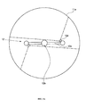
- Fig. 3 and Fig. 4 are illustrative diagrams which show a relationship between the branch pipes 12c of the spray apparatus 12 in the gas absorbing tower 10 and the spray nozzles 12d. Furthermore, Fig. 3 and Fig. 4 represent the spray region of the spray nozzles 12d by single-dotted lines.
- the spray nozzles 12d are installed such that the spray direction is inclined inwards with respect to the branch pipes 12c, in the same plane as the branch pipes 12c. More specifically, as shown in Fig. 3B , the spray nozzles 12d are installed in such a manner that the angle ⁇ formed between the extension line of the center line of the spray region of the spray nozzles 12d, and the lengthwise direction of the branch pipes 12c, is an acute angle.
- the angle ⁇ is desirably set to be one half of the spray angle of the spray nozzles 12d, in such a manner that the droplets sprayed from the spray nozzles 12d do not strike the water conduit pipe 12b. This is in order to prevent deterioration of the water conduit pipe 12b that occurs when the droplets sprayed from the spray nozzles 12d strike the water conduit pipe 12b.
- the angle ⁇ is set to 45 degrees
- the angle ⁇ is set to 60 degrees.
- the spray nozzles 12d By arranging the spray nozzles 12d in this way so as to have an acute angle of installation ⁇ , it is possible to lengthen the distance between the perimeter wall section 11a of the absorbing tower main body 11 and the spray ports of the spray nozzles 12d. Consequently, as shown in Fig. 3A , droplets are sprayed in a broad range including the central portion, in the horizontal cross-section of the absorbing tower main body 11. Therefore, it is possible to raise the contact surface area between the exhaust gas and the absorbing liquid, compared to a case where the spray nozzles 12d are disposed perpendicularly with respect to the branch pipes 12c (see Fig. 10 ).
- the spray nozzles 12d are arranged perpendicularly with respect to branch pipes 12c. Accordingly, the flight distance of the liquid droplets sprayed in this portion becomes longer, and hence the contact time between the exhaust gas and the absorbing liquid can be increased.
- a spray nozzle 12d1 and a spray nozzle 12d2 are provided respectively at the front end and near the center of each of the branch pipes 12c.
- the spray nozzle 12d1 and the spray nozzle 12d2 may each have the same angle of installation ⁇ ( ⁇ 1, ⁇ 2) with respect to the branch pipe 12c, or may have different angles of installation.
- angles of installation ⁇ of the plurality of spray nozzles 12d may be adjusted, as appropriate.
- the angle of installation ⁇ of at least one spray nozzle 12d, of the plurality of spray nozzles 12d is an acute angle
- the angle of installation ⁇ of the remaining spray nozzle 12d may be equal to or greater than 90 degrees.
- the angles of installation ⁇ ( ⁇ 1, ⁇ 2) of the two spray nozzles 12d1, 12d2 are desirably adjusted in such a manner that the angle ⁇ 1 formed between the line of extension of the center line of the spray region of the spray nozzle 12d1 and the lengthwise direction of the branch pipe 12c, and the angle ⁇ 2 formed between the line of extension of the center line of the spray region of the spray nozzle 12d1 and the lengthwise direction of the branch pipe 12c are both acute angles, and that ⁇ 1 ⁇ ⁇ 2.
- the spray nozzles 12d can be connected to the branch pipe 12c by joints such as elbow or straight elbow joints, which are common pipe junctions.
- joints such as elbow or straight elbow joints, which are common pipe junctions.
- long nipples are used as the branch pipes 12c, elbows are screwed into either end thereof, straight elbows are screwed into these elbows, and spray nozzles 12d having a straight shape are provided on these straight elbows.
- the spray nozzles 12d have a 90-degree bend section, it is also possible to connect the spray nozzles 12d directly to the elbows, without using the straight elbows.
- a straight-shaped spray nozzle having any one of various spray patterns, such as a fan-shaped, full cone, or hollow cone pattern, for example, as the spray nozzle 12d.
- a spray nozzle 12d of this kind it is also possible to adjust the angle of inclination with respect the horizontal plane, as well as the angle of installation within the horizontal plane.
- By adjusting the angle of inclination of the spray nozzles 12d it is possible to cause the sprayed droplets to be directed upwards or downwards with respect to the horizontal plane. Consequently, the flight distance of the sprayed droplets is increased and the removal rate of the harmful substances is improved.
- the flight distance in this case indicates the distance travelled by the droplets sprayed from the spray ports of the spray nozzles 12d until reaching the perimeter wall section 11a of the absorbing tower main body 11.
- the gas absorbing tower 10 When the gas absorbing tower 10 is employed as an exhaust gas processing apparatus in a ship, the absorbing tower main body 11 must be compact in size and the installation space thereof must be small. In order to make the absorbing tower main body 11 compact in size, it is necessary to improve the removal rate of harmful substances.
- the discharge pressure declines as the flow rate of the absorbing liquid decreases, the absorbing liquid forms a liquid film at the spray port, and there is a risk that droplets will not be formed.
- the spray nozzles 12d use hollow cone nozzles 120 such as those shown in Fig. 5.
- Fig. 5 is a cross-sectional schematic drawing showing an example of a hollow cone nozzle 120.
- the hollow cone nozzle 120 is composed by a nozzle main body 121 and a cap 122.
- the nozzle main body 121 includes an inflow hole 121a into which the absorbing liquid flows, and a revolving flow chamber 121b which is connected in substantially perpendicular fashion to the inflow hole 121a.
- a spray port 122a is provided in the cap 122.
- the absorbing liquid supplied from the inflow hole 121a to the revolving flow chamber 121b creates a revolving flow which revolves about the axis of the revolving flow chamber 121b. Consequently, an air core 123 is produced about the axis of the revolving flow chamber 121b, and the absorbing liquid sprayed from the spray port 122a forms a hollow cone shape.
- the air core 123 is situated inside the hollow cone nozzle 120, then the diameter passing foreign matter is structurally larger than with a fan-shaped nozzle or a full cone nozzle. Therefore, by using a hollow cone nozzle 120 for the spray nozzles 12d, it is possible to prevent blockages of the spray nozzles 12d caused by foreign substance in the seawater or alkali liquid, which is used as the absorbing liquid. Consequently, when a composition which filters the absorbing liquid with a strainer is adopted, in order to prevent blockage of foreign substance in the spray nozzles 12d, it is possible to adopt a coarser mesh for the strainer, and the pressure loss can be reduced and the maintenance frequency can also be reduced.
- the method for increasing the surface area of the droplets may be: (1) a method which increases the flow rate of absorbing liquid supplied to the supply nozzles 12d; (2) a method which reduces the diameter of the droplets sprayed from the spray nozzles 12d; or (3) a method which lengthens the flight time of the droplets sprayed from the spray port of the spray nozzles 12d to the perimeter wall section 11a; or the like.
- the spray nozzles 12d are installed in such a manner that the angle of inclination ⁇ formed between the center line of the spray region of the spray nozzles 12d and the branch pipes 12c in the lengthwise direction of the branch pipes 12c is an acute angle, then the distance between the perimeter wall section 11a of the absorbing tower main body 11 and the spray port of the spray nozzles 12d can be lengthened. Therefore, it is possible to increase the contact surface area between the exhaust gas and the absorbing liquid, since the droplets are sprayed in a broad range including the central portion, in the horizontal cross-section of the absorbing tower main body 11. Furthermore, by lengthening the distance between the perimeter wall section 11a of the absorbing tower main body 11 and the spray ports of the spray nozzles 12d, the flight distance of the droplets is extended, and the contact time between the exhaust gas and the absorbing liquid can be increased.
- the contact properties between the exhaust gas and the absorbing liquid (principally, the contact surface area and the contact time) can be raised, and therefore the efficiency of the removal of harmful substrates by each spray nozzle 12d is increased, and the number of spray nozzles 12d that need to be provided in order to achieve the desired removal rate in the gas absorbing tower 10 is reduced. Since the number of branch pipes 12c that need to be installed on the water conduit pipe 12b (trunk pipe) is also reduced in accordance with the reduction in the number of installed spray nozzles 12d, then the length of the water conduit pipe 12b can also be shortened. Consequently, it is possible to restrict the height of the absorbing tower main body 11 required to accommodate the water conduit pipe 12b, and therefore it is possible to make the accommodating tower main body 11 compact in size.
- the height of the absorbing tower main body 11 is restricted and it is possible to dispose the gas absorbing tower 10 in the engine room or the deck of the ship, and therefore the installation properties of the gas absorbing tower 10 acting as an exhaust gas processing apparatus is improved.
- the vertical axis represents the SO 2 removal rate (%) and the horizontal axis represents the gas flow rate (m/s).
- the graph (X) shows the target line of the SO 2 removal rate.
- Fig. 6 shows a graph for a case where branch pipes are provided at a pitch of 90 mm on the water conduit pipe, and 64 spray nozzles are provided. Furthermore, seawater is supplied as an absorbing liquid at a rate of 190 liters per minute to the spray nozzles in graph (A), and seawater is supplied as an absorbing liquid at a rate of 180 liters per minute to the spray nozzles in graph (B) .
- Fig. 7A is a graph showing the relationship between the diameter passing foreign substance in the spray nozzles and the mean particle size of the droplets
- Fig. 7B is a graph showing the relationship between the diameter passing foreign substance in the spray nozzles and the flow rate per spray nozzle at a spray pressure of 0.3 MPa.
- the vertical axis represents the mean particle size ( ⁇ m) and the horizontal axis represents the diameter passing foreign substance (mm).
- the vertical axis represents the flow rate (L/min) and the horizontal axis represents the diameter passing foreign substance (mm).
- the graph (D1) represents a case where a fan-shaped nozzle is used for the spray nozzles
- the graph (E1) represents a case where a full cone nozzle is used for the spray nozzles
- the graph (F1) represents a case where a hollow cone nozzle is used for the spray nozzles.
- the graph (D2) represents a case where a fan-shaped nozzle is used for the spray nozzles
- the graph (E2) represents a case where a full cone nozzle is used for the spray nozzles
- the graph (F2) represents a case where a hollow cone nozzle is used for the spray nozzles.
- Fig. 8 is a graph showing a relationship between the spray pressure of the spray nozzle and the mean particle size of the droplets.
- the vertical axis represents the Sauter mean particle size d 32 ( ⁇ m) and the horizontal axis represents the spray pressure P (MPa).
- the graph (G) represents a case where a fan-shaped nozzle is used for the spray nozzles
- the graph (H) represents a case where a full cone nozzle is used for the spray nozzles
- the graph (I) represents a case where a hollow cone nozzle is used for the spray nozzles.
- Fig. 9 is a graph showing a relationship between the type of the spray nozzle and the SO X removal rate.
- the vertical axis represents the SO X removal rate (%) and the horizontal axis represents the gas flow rate (m/s).
- the graph (J) represents a case where a fan-shaped nozzle is used for the spray nozzles
- the graph (K) represents a case where a full cone nozzle is used for the spray nozzles
- the graph (L) represents a case where a hollow cone nozzle is used for the spray nozzles.
Landscapes
- Engineering & Computer Science (AREA)
- Chemical & Material Sciences (AREA)
- Environmental & Geological Engineering (AREA)
- Chemical Kinetics & Catalysis (AREA)
- Analytical Chemistry (AREA)
- General Chemical & Material Sciences (AREA)
- Oil, Petroleum & Natural Gas (AREA)
- Biomedical Technology (AREA)
- Health & Medical Sciences (AREA)
- Combustion & Propulsion (AREA)
- Mechanical Engineering (AREA)
- General Engineering & Computer Science (AREA)
- Gas Separation By Absorption (AREA)
- Treating Waste Gases (AREA)
- Exhaust Gas After Treatment (AREA)
- Nozzles (AREA)
Abstract

Description
- The present invention relates to an exhaust gas processing apparatus for removing harmful substances (principally, sulfur oxides (SOx)) from exhaust gas.
- An exhaust gas processing apparatus using a cyclone scrubber is known as a removal apparatus for removing SOX from exhaust gas (see, for example, Patent Document 1). The exhaust smoke desulfurization apparatus described in
Patent Document 1 brings the gas that revolves up from the bottom of a cylindrical tower, into contact with liquid sprayed in the radial direction of the tower from spray nozzles installed at suitable intervals apart on a spray pipe installed vertically on the central axis of the tower, and absorbs or collects dirt. - In
Patent Document 1, the spray nozzles are disposed so as to be directed in the same direction of rotation as the gas flow (rotating flow) which rises up while rotating from the bottom of the absorbing column, and are arranged so as to have an inclination with respect to the horizontal plane in order to spray the absorbing liquid upwards with respect to the horizontal direction. The spray mist emitted from the spray nozzles is sprayed in a substantially conical shape from a horizontal direction to an upward direction, for example. - Patent Document 1: Japanese Patent No.
3073972 - However, in the abovementioned exhaust smoke desulfurization apparatus, the angle of installation of the spray nozzles in the horizontal plane is not mentioned. Normally, as shown in
Fig. 10 ,spray nozzles 102 are connected to abranch pipe 101 of thespray pipe 100 via an elbow having a bend section of 90 degrees, and therefore thespray nozzles 102 are disposed perpendicularly with respect to thebranch pipe 101. In this case, if a fan-shaped spray pattern is adopted for thespray nozzles 102, then since the spray angle is 120 degrees at the broadest, the absorbing liquid is not sprayed in at least 30 degrees of the central direction. Furthermore, since the distance between the circumferential wall of thebranch pipe 101 on the extending direction side, and the spray port of thespray nozzle 102 is short, then the distance of flight of the absorbing liquid sprayed in this portion is also short. - The removal rate when removing harmful substances in the exhaust gas by a cyclone scrubber is correlated to the contact properties between the exhaust gas and the absorbing liquid (principally, the contact surface area and the contact time). Consequently, sufficient contact surface area is not achieved when the droplets of the absorbing liquid sprayed from the spray nozzles are not dispersed in a broad range, and furthermore, sufficient contact time is not achieved when the flight distance is short, and hence there is a problem in that a high removal rate cannot be obtained. In this case, in order to obtain a desired removal rate, it is necessary to ensure contact properties by increasing the number of spray nozzles, and increase in the size of the cyclone scrubber cannot be avoided.
- The present invention was devised in view of these circumstances, an object thereof being to provide an exhaust gas processing apparatus whereby the removal rate of harmful substances can be improved and compact size can be achieved.
- The present invention is an exhaust gas processing apparatus absorbing gas by creating contact between gas and liquid, the apparatus including: an absorbing tower main body in which an internal space is formed; spray apparatus which sprays liquid in a prescribed region in an up/down direction of the internal space; and a gas supply apparatus which introducing gas into the absorbing tower main body, wherein the spray apparatus has: a trunk pipe extending in the up/down direction in a prescribed region of the internal space; branch pipes coupled to the trunk pipe and extending towards an inner wall of the absorbing tower main body; and spray nozzles spraying liquid supplied from the branch pipes; and the spray nozzles are installed such that an angle formed between the center line of the spray region of the spray nozzles and the lengthwise direction of the branch pipes is an acute angle.
- According to the exhaust gas processing apparatus, since the spray nozzles are installed in such a manner that the angle formed between the center line of the spraying region of the spray nozzles and the lengthwise direction of the branch pipes is an acute angle, then it is possible to lengthen the distance between the perimeter wall section of the absorbing tower main body and the spray ports of the spray nozzles. Therefore, it is possible to increase the contact surface area between the exhaust gas and the absorbing liquid, since the droplets are sprayed in a broad range including the central portion, in the horizontal cross-section of the absorbing tower main body. Furthermore, by lengthening the distance between the perimeter wall section of the absorbing tower main body and the spray ports of the spray nozzles, the flight distance of the droplets is extended, and the contact time between the exhaust gas and the absorbing liquid can be increased.
- In this way, the contact properties between the exhaust gas and the absorbing liquid (principally, the contact surface area and the contact time) can be raised, and therefore the efficiency of the removal of harmful substrates by each spray nozzle is raised, and the number of spray nozzles that need to be provided in order to achieve the desired removal rate in the gas processing apparatus is reduced. Since the number of branch pipes that need to be installed on the trunk pipe becomes lower, as the number of installed spray nozzles is reduced, then it is possible to shorten the trunk pipe. Consequently, it is possible to restrict the height of the absorbing tower main body for accommodating the water conduit pipe, and therefore it is possible to make the accommodating tower main body compact in size.
- In the exhaust gas processing apparatus described above, desirably, the spray nozzles have an angle of installation by which the trunk pipe is not included within the spraying region.
- Furthermore, in the exhaust gas processing apparatus described above, a plurality of the spray nozzles may be provided on each branch pipe, and the angle of installation of at least one of the spray nozzles may be an acute angle.
- Moreover, in the exhaust gas processing apparatus described above, the angle of installation, with respect to the branch pipe, of the spray nozzle provided on the outer side in the radial direction may be smaller than the angle of installation of the spray nozzle provided in the inner side in the radial direction.
- Moreover, in the exhaust gas processing apparatus described above, the spray nozzle may be a hollow cone nozzle.
- According to the present invention, the removal rate of harmful substances is improved and a compact size can be achieved, in an exhaust gas processing apparatus.
-
-
Fig. 1 is a schematic diagram showing an exhaust gas processing system centered on a gas absorbing tower relating to an embodiment of the present invention; -
Fig. 2A is an upper surface schematic drawing of the gas absorbing tower andFig. 2B is a cross-sectional schematic drawing of the gas absorbing tower; -
Figs. 3A and3B are illustrative diagrams showing a relationship between a branch pipe and a spray nozzle in a spray apparatus of the gas absorbing tower; -
Figs. 4A and4B are illustrative diagrams showing a relationship between a branch pipe and a spray nozzle in a spray apparatus of the gas absorbing tower; -
Fig. 5 is a cross-sectional schematic drawing showing one example of a hollow cone nozzle; -
Fig. 6 is a graph showing the SO2 removal rate in a case where the spray nozzles are installed at an angle of θ = 90°, and in a case where the spray nozzles are installed at an angle of θ = 45°, with respect to the branch pipe; -
Fig. 7A is a graph showing the relationship between the diameter passing foreign substance in the spray nozzles and the mean particle size of the droplets, andFig. 7B is a graph showing the relationship between the diameter passing foreign substance in the spray nozzles and the flow rate per spray nozzle at a spray pressure of 0.3 MPa; -
Fig: 8 is a graph showing a relationship between the spray pressure of the spray nozzle and the mean particle size of the droplets; -
Fig. 9 is a graph showing a relationship between the type of the spray nozzle and the SOX removal rate; and -
Fig. 10 is an illustrative diagrams showing a relationship between a.branch pipe and a spray nozzle in a spray apparatus of the gas absorbing tower. - Below, embodiments of the present invention are described in detail with reference to the accompanying drawings.
Fig. 1 is a schematic drawing showing an exhaust gas processing system centered on a gas absorbing tower which forms an exhaust gas processing apparatus relating to the present embodiment. The exhaust gas processing system relating to the present embodiment contemplates a system which removes sulfur dioxide (SO2) included in exhaust gas emitted from an engine which is used in a ship. The invention is not limited to this, however, and the exhaust gas processing system relating to the present embodiment can be applied to processing of various exhaust gases including substances such as nitrogen oxide, sulfur oxide, and the like. - ' As shown in
Fig. 1 , the exhaust gas processing system is principally composed by agas absorbing tower 10 which receives a supply of exhaust gas from theengine 20, aseawater pump unit 30 provided with a seawater pressurization pump and a seawater suction pump, awastewater tank 40, and afilter unit 50 for filtering the wastewater. - The exhaust gas emitted from the
engine 20 is introduced into thegas absorbing tower 10. This exhaust gas contains 50 to 1500 ppm of sulfur dioxide (SO2). As this exhaust gas rises up inside thegas absorbing tower 10, seawater that has been introduced into thegas absorbing tower 10 is introduced via theseawater pump unit 30, and a gas liquid contact is created. - The sulfur dioxide in the exhaust gas is absorbed and removed by the seawater, which is alkaline, as indicated in Formulas (1) and (2) given below.
SO2 + H2O → H2SO3 (1)
H2SO3 + 2AOH → A2SO3 + 2H2O (2)
In the Formulas (1) and (2) above, A represents alkaline. - The exhaust gas from which the sulfur dioxide has been removed in this way is expelled into the atmosphere from the top of the
gas absorbing tower 10. - The seawater sprayed inside the
gas absorbing tower 10 drops down under gravity along the inner circumferential surface of thegas absorbing tower 10, and collects in a collecting section below thegas absorbing tower 10. The collected seawater is expelled to thewastewater tank 40 via thewastewater pump unit 30, and is then filtered by thefilter unit 50 and discharged into the sea. - Next, a concrete description of the
gas absorbing tower 10 which is an exhaust gas processing apparatus relating to the present embodiment will be given.Fig. 2A is an upper surface schematic drawing of thegas absorbing tower 10 relating to the present embodiment, andFig. 2B is cross-sectional schematic drawing of thegas absorbing tower 10. - As shown in
Figs. 2A and2B , thegas absorbing tower 10 is provided with: an absorbing towermain body 11 in which an internal space is formed in the up/down direction; aspray apparatus 12 which sprays liquid in the form of a mist in a prescribed region, in the up/down direction, of the internal space of the absorbing towermain body 11; agas supply apparatus 13 which introduces gas into the absorbing towermain body 11 from a position below the region where thespray apparatus 12 sprays liquid;liquid return members 14 which are provided in a position above the region where thespray apparatus 12 sprays liquid, which projects in a ring shape towards the central axis from the inner wall surface of the absorbing towermain body 11, and of which at least the front end on the central axis side is bent back downwards; and abaffle 15 which is provided at a position below thespray apparatus 12. Here, thespray apparatus 12 is connected to theseawater pump unit 30 shown inFig. 1 , and thegas supply apparatus 13 is connected to theengine 20 shown inFig. 1 . - The absorbing tower
main body 11 is constituted by a round cylindricalperimeter wall section 11a and a circularbottom wall section 11b. Theperimeter wall section 11a is formed with the same diameter in all parts. The upper end portion of theperimeter wall section 11a is open and anopening section 11c is formed therein. In the present embodiment, the absorbing towermain body 11 has a round cylindrical shape, but the shape of the absorbing towermain body 11 is not limited to this and may be a square cylinder shape, for example. - The
spray apparatus 12 is disposed on the central axis of the absorbing towermain body 11. Thespray apparatus 12 is constituted by awater supply pipe 12a which is inserted inside the absorbing towermain body 11 from outside the absorbing towermain body 11 and which extends to a central position of the absorbing towermain body 11, awater conduit pipe 12b forming a trunk pipe which is coupled to the inserted end portion of thewater supply pipe 12a and extends to a prescribed region, in the up/down direction, of the internal space of the absorbing towermain body 11,branch pipes 12c which are coupled to thewater conduit pipe 12b and extend toward theperimeter wall section 11a of the absorbing towermain body 11, andspray nozzles 12d which are provided respectively at the front end of the eachbranch pipes 12c and which spray liquid supplied from thebranch pipes 12c in a prescribed region. As described in detail hereinafter, thesespray nozzles 12d are each installed in such a manner that an acute angle is formed between the center line of the spray region of thespray nozzle 12d, and the lengthwise direction of thebranch pipe 12c. - The
branch pipes 12c which are disposed in a plurality of levels in the up/down direction are arranged so thatbranch pipes 12c that are mutually adjacent in the up/down direction intersect with each other. The arrangement of thebranch pipes 12c with respect to thewater conduit pipe 12b is not limited to this; for example, a composition may be adopted in which fourbranch pipes 12c are arranged at 90 degree intervals apart on the same perimeter portion of thewater conduit pipe 12b. Furthermore, the material of thespray nozzles 12d is desirably an austenite type stainless steel material, in order to obtain corrosion resistance when seawater is used as the absorbing liquid. - The
gas supply apparatus 13 is provided in such a manner that the gas output direction is aligned with the tangential direction of theperimeter wall section 11a of the absorbing towermain body 11. Consequently, the exhaust gas introduced from thegas supply apparatus 13 is sprayed in a horizontal direction along the inner circumferential surface of theperimeter wall section 11a. - The
liquid return members 14 each have a bend-back surface section 14a which projects in a ring shape towards the central axis from theperimeter wall section 11a of the absorbing towermain body 11, a bend-back piece 14b which is bent back downwards from the front end of the central axis side of the bend-back surface section 14a, aliquid reservoir wall 14d which projects to the upper side from the front end of the bend-back surface section 14a so as to create aliquid reservoir section 14c, and a throughhole 14e which allows the liquid collected in theliquid reservoir section 14c to drop down. - The region on the central axis side which is surrounded by the bend-
back pieces 14b and theliquid reservoir walls 14d of theliquid return members 14 attached to the absorbing towermain body 11 constitutes anopening section 14g (seeFig. 2B ). Thisopening section 14g is composed so as to have an internal diameter of approximately 5 to 8 tenths that of theopening section 11c of the absorbing towermain body 11. By this composition, it is possible to suppress pressure loss caused by installing theliquid return members 14 on the absorbing towermain body 11. - The
baffle 15 is constituted by acircular disk section 15a, andleg sections 15b which couple thecircular disk section 15a with theperimeter wall section 11a of the absorbing towermain body 11. A gap for liquid droplets to flow through is formed between the outer circumferential portion of thecircular disk section 15a and theperimeter wall section 11a of the absorbing towermain body 11. Thebaffle 15 divides the interior of the absorbing towermain body 11 into a region where liquid is sprayed by thespray apparatus 12 and a region where liquid is collected for drainage to the outside of the absorbing towermain body 11. Awastewater pipe 16 for discharging liquid to outside the absorbing towermain body 11 is provided below thebaffle 15. - The exhaust gas processing in the
gas absorbing tower 10 which is composed in this way will now be described. Exhaust gas discharged from an engine is introduced by thegas supply apparatus 13 at a position below the region where thespray apparatus 12 sprays liquid. This exhaust gas rises up inside the absorbing towermain body 11 while revolving so as to follow theperimeter wall section 11a. - Meanwhile, seawater is introduced into the
water conduit pipe 12b via thewater supply pipe 12a. The seawater is then sprayed towards theperimeter wall section 11a of the absorbing towermain body 11, from thespray nozzles 12d which are provided on the plurality of levels ofbranch pipes 12c. - Consequently, the exhaust gas which rises up while revolving inside the absorbing tower
main body 11 makes gas/liquid contact with the seawater sprayed from thespray nozzles 12d provided on thebranch pipes 12c which are provided in the respective levels, and the sulfur dioxide in the exhaust gas is absorbed and removed. The exhaust gas from which the sulfur dioxide has been removed is discharged into the atmosphere from theopening section 11c provided in the upper portion of the absorbing towermain body 11. - The seawater which forms into liquid droplets is pressed against the
perimeter wall section 11a by the centrifugal force of the revolving flow and falls under its own weight. However, a portion of the seawater rises up through the interior of the absorbing towermain body 11 due to the rising and revolving flow. - In the central portion of the absorbing tower
main body 11, the gas flow rate is 0 m/s or a value to close to same, and since the gas flow rate is faster in the vicinity of theperimeter wall section 11a than in the central portion, the seawater rises up along theperimeter wall section 11a due to the centrifugal force. The seawater which rises up along theperimeter wall section 11a is impeded from rising further by the lowermostliquid return member 14, and collects on the lower surface of the bend-back surface section 14a and the periphery of the bend-back piece 14b. When the collected liquid exceeds a certain amount, the liquid forms droplets and drops down under its own weight. - However, a portion of the seawater passes up over the bend-
back piece 14b rather than turning into liquid droplets, and due to the centrifugal force, rises up along the inner perimeter surface of the bend-back piece 14b and theliquid reservoir wall 14d of theliquid return member 14, and rises up further along theperimeter wall section 11a between theliquid return member 14 and the nextliquid return member 14. The seawater which reaches theliquid return member 14 of the next level in this way is impeded from rising up further by theliquid return member 14, and collects on the lower surface of the bend-back surface section 14a and the periphery of the bend-back piece 14b. When the collected liquid exceeds a certain amount, the liquid forms a droplet and drops down under its own weight. The droplets which drop down collect in theliquid reservoir section 14c of the lower level, and upon exceeding a certain amount, pass through the throughhole 14e and drop down into the absorbing towermain body 11. - The gas flow rate is faster in the vicinity of the
perimeter wall section 11a of the absorbing towermain body 11 than in the central portion of the absorbing towermain body 11, and therefore when the throughhole 14e is provided in the vicinity of theperimeter wall section 11a, a situation may arise in which the droplets do not drop down from the throughhole 14e due to the effects of the upward flow. Therefore, by providing the throughhole 14e at a position distanced from theperimeter wall section 11a where the gas flow rate is faster than in the vicinity of theperimeter wall section 11a, the effects of the upward flow are weaker and it is possible to make the droplets drop down via the throughhole 14e. - Since
liquid return members 14 are provided in a plurality of levels in the up/down direction, the rising up of seawater is impeded a plurality of times by theliquid return members 14. Therefore, it is possible to effectively prevent situations where the seawater rises up and flows out from theopening section 11c of the absorbing towermain body 11. - Furthermore, although the
liquid return members 14 are installed on the absorbing towermain body 11, since theliquid return members 14 have a shape which projects in a ring shape towards the central axis from theperimeter wall section 11a of the absorbing towermain body 11 and anopening section 14g is formed on the side of the central axis, then it is possible to reduce the pressure loss caused by the installation of theliquid return members 14. Furthermore, no blockages occur due to theliquid return members 14, and complex maintenance is not necessary. - The droplets that drop down are prevented from revolving by the
baffle 15 which is disposed below the absorbing towermain body 11, and then pass along thebaffle 15 and theperimeter wall section 11a, and collect in the collecting section which is constituted by thebottom wall section 11b and theperimeter wall section 11a peripheral to same, of the absorbing towermain body 11. The collected liquid is discharged to the outside of the absorbing towermain body 11 via thewastewater pipe 16. - Next, the
spray nozzle 12d of thespray apparatus 12 in thegas absorbing tower 10 will be described in detail. Firstly, the angle of installation of thespray nozzles 12d with respect to thebranch pipes 12c is described with reference to the drawings.Fig. 3 andFig. 4 are illustrative diagrams which show a relationship between thebranch pipes 12c of thespray apparatus 12 in thegas absorbing tower 10 and thespray nozzles 12d. Furthermore,Fig. 3 andFig. 4 represent the spray region of thespray nozzles 12d by single-dotted lines. - As shown in
Fig. 3A , thespray nozzles 12d are installed such that the spray direction is inclined inwards with respect to thebranch pipes 12c, in the same plane as thebranch pipes 12c. More specifically, as shown inFig. 3B , thespray nozzles 12d are installed in such a manner that the angle θ formed between the extension line of the center line of the spray region of thespray nozzles 12d, and the lengthwise direction of thebranch pipes 12c, is an acute angle. - The angle θ is desirably set to be one half of the spray angle of the
spray nozzles 12d, in such a manner that the droplets sprayed from thespray nozzles 12d do not strike thewater conduit pipe 12b. This is in order to prevent deterioration of thewater conduit pipe 12b that occurs when the droplets sprayed from thespray nozzles 12d strike thewater conduit pipe 12b. For example, when the spray angle of thespray nozzles 12d is 90 degrees, then the angle θ is set to 45 degrees, and when the spray angle of thespray nozzles 12d is 120 degrees, then the angle θ is set to 60 degrees. - By arranging the
spray nozzles 12d in this way so as to have an acute angle of installation θ, it is possible to lengthen the distance between theperimeter wall section 11a of the absorbing towermain body 11 and the spray ports of thespray nozzles 12d. Consequently, as shown inFig. 3A , droplets are sprayed in a broad range including the central portion, in the horizontal cross-section of the absorbing towermain body 11. Therefore, it is possible to raise the contact surface area between the exhaust gas and the absorbing liquid, compared to a case where thespray nozzles 12d are disposed perpendicularly with respect to thebranch pipes 12c (seeFig. 10 ). - Furthermore, by disposing the
spray nozzles 12d in this way so as to have an acute angle of installation θ, the distance between theperimeter wall section 11a on the side in the direction of extension of thebranch pipes 12c, and the spray ports of thespray nozzles 12d is longer than in a case where thespray nozzles 12d are arranged perpendicularly with respect tobranch pipes 12c. Accordingly, the flight distance of the liquid droplets sprayed in this portion becomes longer, and hence the contact time between the exhaust gas and the absorbing liquid can be increased. - Consequently, by providing
spray nozzles 12d at an acute angle with respect to thebranch pipes 12c, it is possible to raise the contact properties between the exhaust gas and the absorbing liquid (principally, the contact surface area and the contact time), compared to cases where thespray nozzles 12d are provided perpendicularly with respect to thebranch pipes 12c. - Furthermore, as shown in
Fig. 4A , it is possible to provide a plurality ofspray nozzles 12d (twospray nozzles 12d inFig. 4A ) on onebranch pipe 12c. InFig 4A , a spray nozzle 12d1 and a spray nozzle 12d2 are provided respectively at the front end and near the center of each of thebranch pipes 12c. The spray nozzle 12d1 and the spray nozzle 12d2 may each have the same angle of installation θ (θ1, θ2) with respect to thebranch pipe 12c, or may have different angles of installation. By adjusting the angles of installation θ (θ1, θ2) of the two spray nozzles 12d1, 12d2, it is possible to spray droplets in a broader range, compared to when onespray nozzle 12d is provided on eachbranch pipe 12c. - It is also possible to adjust the angles of installation θ of the plurality of
spray nozzles 12d, as appropriate. For example, when the angle of installation θ of at least onespray nozzle 12d, of the plurality ofspray nozzles 12d, is an acute angle, then the angle of installation θ of the remainingspray nozzle 12d may be equal to or greater than 90 degrees. However, it is desirable to adopt the following mode in respect of the angle of installation θ of the plurality ofspray nozzles 12d. - In other words, as shown in
Fig. 4B , the angles of installation θ (θ1, θ2) of the two spray nozzles 12d1, 12d2 are desirably adjusted in such a manner that the angle θ1 formed between the line of extension of the center line of the spray region of the spray nozzle 12d1 and the lengthwise direction of thebranch pipe 12c, and the angle θ2 formed between the line of extension of the center line of the spray region of the spray nozzle 12d1 and the lengthwise direction of thebranch pipe 12c are both acute angles, and that θ1 < θ2. By adjusting the angles in this way, even in cases where a plurality ofspray nozzles 12d (12d1, 12d2) are provided on onebranch pipe 12c, it is possible to spray the absorbing liquid in a broad range, while taking consideration to avoid the absorbing liquid sprayed from the spray nozzles 12d1, 12d2 striking thewater conduit pipe 12b. - In this way, by adopting a composition in which a plurality of
spray nozzles 12d are provided on onebranch pipe 12c, it is possible to broaden the spraying region with respect to the internal space of the absorbing towermain body 11. Therefore, it is possible to raise yet further the contact properties between the exhaust gas and the absorbing liquid (principally, the contact surface area and the contact time), and the removal rate of the harmful substances is improved. - The
spray nozzles 12d can be connected to thebranch pipe 12c by joints such as elbow or straight elbow joints, which are common pipe junctions. For example, long nipples are used as thebranch pipes 12c, elbows are screwed into either end thereof, straight elbows are screwed into these elbows, andspray nozzles 12d having a straight shape are provided on these straight elbows. Furthermore, when thespray nozzles 12d have a 90-degree bend section, it is also possible to connect thespray nozzles 12d directly to the elbows, without using the straight elbows. - It is possible to adopt a straight-shaped spray nozzle having any one of various spray patterns, such as a fan-shaped, full cone, or hollow cone pattern, for example, as the
spray nozzle 12d. By adopting aspray nozzle 12d of this kind, it is also possible to adjust the angle of inclination with respect the horizontal plane, as well as the angle of installation within the horizontal plane. By adjusting the angle of inclination of thespray nozzles 12d, it is possible to cause the sprayed droplets to be directed upwards or downwards with respect to the horizontal plane. Consequently, the flight distance of the sprayed droplets is increased and the removal rate of the harmful substances is improved. The flight distance in this case indicates the distance travelled by the droplets sprayed from the spray ports of thespray nozzles 12d until reaching theperimeter wall section 11a of the absorbing towermain body 11. - When the
gas absorbing tower 10 is employed as an exhaust gas processing apparatus in a ship, the absorbing towermain body 11 must be compact in size and the installation space thereof must be small. In order to make the absorbing towermain body 11 compact in size, it is necessary to improve the removal rate of harmful substances. - Furthermore, by decreasing the amount of the absorbing liquid sprayed from the
spray nozzles 12d of thespray apparatus 12 in thegas absorption tower 10, in accordance with decrease in the load on the source of the exhaust gas, such as theengine 20 or boiler, it becomes possible to reduce the motive force required in theseawater pump unit 30. However, when the amount of absorbing liquid sprayed from thespray nozzles 12d decreases, then there is a risk of deterioration in the properties of the droplets sprayed from thespray nozzles 12d. For example, when fan-shaped nozzles are used as thespray nozzles 12d, then the discharge pressure declines as the flow rate of the absorbing liquid decreases, the absorbing liquid forms a liquid film at the spray port, and there is a risk that droplets will not be formed. - Therefore, desirably, the
spray nozzles 12d usehollow cone nozzles 120 such as those shown inFig. 5. Fig. 5 is a cross-sectional schematic drawing showing an example of ahollow cone nozzle 120. As shown inFig. 5 , thehollow cone nozzle 120 is composed by a nozzlemain body 121 and acap 122. The nozzlemain body 121 includes aninflow hole 121a into which the absorbing liquid flows, and a revolvingflow chamber 121b which is connected in substantially perpendicular fashion to theinflow hole 121a. Aspray port 122a is provided in thecap 122. By installing thecap 122 on the nozzlemain body 121, the revolvingflow chamber 121b and thespray port 122a are provided in consecutive fashion in the perpendicular direction. - In the revolving
flow chamber 121b, the absorbing liquid supplied from theinflow hole 121a to the revolvingflow chamber 121b creates a revolving flow which revolves about the axis of the revolvingflow chamber 121b. Consequently, anair core 123 is produced about the axis of the revolvingflow chamber 121b, and the absorbing liquid sprayed from thespray port 122a forms a hollow cone shape. - When a
hollow cone nozzle 120 is used for thespray nozzle 12d, then even when the absorbing liquid flow rate supplied to thespray nozzle 12d is reduced, since the absorbing liquid revolves in the revolvingflow chamber 121b and is then sprayed, then a suitable form of the droplets can be maintained, rather than forming a liquid film at thespray port 122a. - Furthermore, since the
air core 123 is situated inside thehollow cone nozzle 120, then the diameter passing foreign matter is structurally larger than with a fan-shaped nozzle or a full cone nozzle. Therefore, by using ahollow cone nozzle 120 for thespray nozzles 12d, it is possible to prevent blockages of thespray nozzles 12d caused by foreign substance in the seawater or alkali liquid, which is used as the absorbing liquid. Consequently, when a composition which filters the absorbing liquid with a strainer is adopted, in order to prevent blockage of foreign substance in thespray nozzles 12d, it is possible to adopt a coarser mesh for the strainer, and the pressure loss can be reduced and the maintenance frequency can also be reduced. - In a
gas absorbing tower 10, in order to improve the removal rate of harmful substances, it is necessary to increase the contact properties (contact surface area and contact time) between the exhaust gas and the absorbing liquid. Here, in order to increase the contact surface area between the exhaust gas and the absorbing liquid, it is necessary to increase the contact surface area of the droplets. The method for increasing the surface area of the droplets may be: (1) a method which increases the flow rate of absorbing liquid supplied to thesupply nozzles 12d; (2) a method which reduces the diameter of the droplets sprayed from thespray nozzles 12d; or (3) a method which lengthens the flight time of the droplets sprayed from the spray port of thespray nozzles 12d to theperimeter wall section 11a; or the like. - (1) In a method which increases the flow rate of absorbing liquid supplied to the
spray nozzles 12d, the flow rate of the absorbing liquid is determined by the flow rate of harmful substances (SOX) supplied to inside the absorbing towermain body 11. In other words, the absorbing liquid flow rate is determined by applying a uniform safety ratio to the equivalent chemical amount required to absorb the SOX. The safety ratio is no less than 1.01 and no more than 1.5, and desirably, 1.2. - (2) In a method which reduces the diameter of the droplets sprayed from the
spray nozzles 12d, generally, in order to make droplets finer in size, the flow rate of the absorbing liquid which is supplied to thespray nozzles 12d needs to be reduced, and the discharge pressure needs to be increased. When the flow rate of the absorbing liquid supplied to eachspray nozzle 12d is reduced, then it is necessary to increase the number ofspray nozzles 12d provided in the whole of thegas absorbing tower 10, which consequently leads to a larger size of thegas absorbing tower 10 and increased costs. Furthermore, when the discharge pressure is raised, the motive force of the pump for discharging absorbing liquid is increased, which leads to increase in the pump capacity and higher power consumption.
Therefore, when the same conditions are set for the absorbing liquid flow rate and the discharge pressure supplied to thespray nozzles 12d, then it is necessary to select nozzles which produce the smallest droplet diameter. Here, when the same conditions are set for the absorbing liquid flow rate and the discharge pressure supplied to thespray nozzles 12d, then the hollow cone nozzle yields the smallest diameter of the sprayed droplets, compared to the fan-shaped nozzle and the full cone nozzle. Consequently, by using a hollow cone nozzle for thespray nozzles 12d, it is possible to reduce the diameter of the droplets sprayed from thespray nozzles 12d, in other words, it is possible to increase the surface area of the droplets and hence to raise the removal rate of harmful substances. - (3) In a method which increases the flight time of the droplets sprayed from the spray ports of the
spray nozzles 12d until reaching theperimeter wall section 11a, the flight distance of the droplets can be lengthened by adjusting the angle of inclination of thespray nozzles 12d in such a manner that the sprayed droplets are directed upwards or downwards with respect to the horizontal surface. By this means, it is possible to lengthen the flight time of the droplets sprayed from the spray ports of thespray nozzles 12d, until reaching theperimeter wall section 11a. - As described above, according to the
gas absorbing tower 10 relating to the present embodiment, since thespray nozzles 12d are installed in such a manner that the angle of inclination θ formed between the center line of the spray region of thespray nozzles 12d and thebranch pipes 12c in the lengthwise direction of thebranch pipes 12c is an acute angle, then the distance between theperimeter wall section 11a of the absorbing towermain body 11 and the spray port of thespray nozzles 12d can be lengthened. Therefore, it is possible to increase the contact surface area between the exhaust gas and the absorbing liquid, since the droplets are sprayed in a broad range including the central portion, in the horizontal cross-section of the absorbing towermain body 11. Furthermore, by lengthening the distance between theperimeter wall section 11a of the absorbing towermain body 11 and the spray ports of thespray nozzles 12d, the flight distance of the droplets is extended, and the contact time between the exhaust gas and the absorbing liquid can be increased. - In this way, the contact properties between the exhaust gas and the absorbing liquid (principally, the contact surface area and the contact time) can be raised, and therefore the efficiency of the removal of harmful substrates by each
spray nozzle 12d is increased, and the number ofspray nozzles 12d that need to be provided in order to achieve the desired removal rate in thegas absorbing tower 10 is reduced. Since the number ofbranch pipes 12c that need to be installed on thewater conduit pipe 12b (trunk pipe) is also reduced in accordance with the reduction in the number of installedspray nozzles 12d, then the length of thewater conduit pipe 12b can also be shortened. Consequently, it is possible to restrict the height of the absorbing towermain body 11 required to accommodate thewater conduit pipe 12b, and therefore it is possible to make the accommodating towermain body 11 compact in size. - According to the
gas absorbing tower 10 relating to the present embodiment, the height of the absorbing towermain body 11 is restricted and it is possible to dispose thegas absorbing tower 10 in the engine room or the deck of the ship, and therefore the installation properties of thegas absorbing tower 10 acting as an exhaust gas processing apparatus is improved. - Furthermore, since the number of members used can be reduced, in accordance with the more compact size of the
gas absorbing tower 10, then it is possible to reduce the price of thegas absorbing tower 10. Moreover, by using a hollow cone nozzle for thespray nozzles 12d, it is possible to reduce the pump power and the maintenance costs, and therefore further price reduction can be achieved. -
Figs. 6A and 6B are graphs showing the SO2 removal rate in a case where (A) the spray nozzles are installed at an angle of θ = 90°, and (B) the spray nozzles are installed at an angle of θ = 45°, with respect to the branch pipe. InFig. 6 , the vertical axis represents the SO2 removal rate (%) and the horizontal axis represents the gas flow rate (m/s). Furthermore, the graph (X) shows the target line of the SO2 removal rate. -
Fig. 6 shows a graph for a case where branch pipes are provided at a pitch of 90 mm on the water conduit pipe, and 64 spray nozzles are provided. Furthermore, seawater is supplied as an absorbing liquid at a rate of 190 liters per minute to the spray nozzles in graph (A), and seawater is supplied as an absorbing liquid at a rate of 180 liters per minute to the spray nozzles in graph (B) . - When spray nozzles are provided at an angle of θ = 90° with respect to the branch pipes, then it is not possible to exceed the target line (X), whatever the gas flow rate (see graph (A)). On the other hand, when the spray nozzles are provided at an angle of θ = 45° with respect to the branch pipes, then the target line (X) is exceeded, at all values of the gas flow rate (see graph (B)).
- As a result of this, by providing the spray nozzles at an acute angle with respect to the branch pipes, it can be seen that the removal rate of the harmful substances is improved, and target performance is obtained, compared to a case where the spray nozzles are provided perpendicularly to the branch pipes.
-
Fig. 7A is a graph showing the relationship between the diameter passing foreign substance in the spray nozzles and the mean particle size of the droplets, andFig. 7B is a graph showing the relationship between the diameter passing foreign substance in the spray nozzles and the flow rate per spray nozzle at a spray pressure of 0.3 MPa. InFig. 7A , the vertical axis represents the mean particle size (µm) and the horizontal axis represents the diameter passing foreign substance (mm). InFig. 7B , the vertical axis represents the flow rate (L/min) and the horizontal axis represents the diameter passing foreign substance (mm). - In
Fig. 7A , the graph (D1) represents a case where a fan-shaped nozzle is used for the spray nozzles, the graph (E1) represents a case where a full cone nozzle is used for the spray nozzles, and the graph (F1) represents a case where a hollow cone nozzle is used for the spray nozzles. InFig. 7B , the graph (D2) represents a case where a fan-shaped nozzle is used for the spray nozzles, the graph (E2) represents a case where a full cone nozzle is used for the spray nozzles, and the graph (F2) represents a case where a hollow cone nozzle is used for the spray nozzles. - As shown in
Fig. 7A , it can be seen that, at the same mean particle size, the diameter passing foreign substance is largest in the case of the hollow cone nozzle and therefore this form has the lowest risk of blocking of the nozzle. As shown inFig. 7B , it can be seen that, at the same flow rate conditions, the diameter passing foreign substance is largest in the case of the hollow cone nozzle and therefore this form has the lowest risk of blocking of the nozzle. - From these results, it can be seen that when a hollow cone nozzle is used for the spray nozzles, it is possible to increase the diameter passing foreign substance, and therefore the risk of the nozzle being closed off by foreign substance can be reduced. Third Example
-
Fig. 8 is a graph showing a relationship between the spray pressure of the spray nozzle and the mean particle size of the droplets. InFig. 8 , the vertical axis represents the Sauter mean particle size d32 (µm) and the horizontal axis represents the spray pressure P (MPa). Furthermore, inFig. 8 , the graph (G) represents a case where a fan-shaped nozzle is used for the spray nozzles, the graph (H) represents a case where a full cone nozzle is used for the spray nozzles, and the graph (I) represents a case where a hollow cone nozzle is used for the spray nozzles. - As shown in
Fig. 8 , it can be seen that, at the same spray pressure and spray flow rate, the mean particle diameter of the hollow cone nozzle is small. - From these results, it can be seen that when a hollow cone nozzle is used for the spray nozzles, the diameter of the droplets sprayed from the spray nozzles can be made smaller, and therefore the removal rate of harmful substances can be raised, due to the increased surface area where the exhaust gas and the absorbing liquid make contact with each other.
-
Fig. 9 is a graph showing a relationship between the type of the spray nozzle and the SOX removal rate. InFig. 9 , the vertical axis represents the SOX removal rate (%) and the horizontal axis represents the gas flow rate (m/s). Furthermore, inFig. 9 , the graph (J) represents a case where a fan-shaped nozzle is used for the spray nozzles, the graph (K) represents a case where a full cone nozzle is used for the spray nozzles, and the graph (L) represents a case where a hollow cone nozzle is used for the spray nozzles. - As shown in
Fig. 9 , it can be seen that, when the same experimental conditions are set for each nozzle, the SOx removal rate is highest in the case of the hollow cone nozzle. - From these results, it can be seen that, when a hollow cone nozzle is used for the spray nozzles, the SOx removal rate of the gas absorbing tower can be improved.
- The present invention is not limited to the embodiments described above, and can be implemented with various modifications. In the embodiments described above, the invention is not limited to the sizes and shapes, and the like, depicted in the accompanying drawings, and suitable modifications are possible within a range that exhibits the beneficial effects of the present invention. Apart from this, it is also possible to implement the invention by making suitable modifications, without departing from the object of the invention.
- The present application is based on Japanese Patent Application No.
2012-276654 filed on 19 December 2012
Claims (5)
- An exhaust gas processing apparatus absorbing gas by creating contact between gas and liquid,
the apparatus comprising:an absorbing tower main body in which an internal space is formed;a spray apparatus for spraying liquid in a prescribed region in an up/down direction of the internal space; and a gas supply apparatus for introducing gas into the absorbing tower main body, whereinthe spray apparatus has:a trunk pipe extending in the up/down direction in a prescribed region of the internal space;branch pipes coupled to the trunk pipe and extending towards an inner wall of the absorbing tower main body; andspray nozzles spraying liquid supplied from the branch pipes; andthe spray nozzles are installed such that an angle formed between the center line of the spray region of the spray nozzles and the lengthwise direction of the branch pipes is an acute angle. - The exhaust gas processing apparatus according to claim 1, wherein the spray nozzles have an angle of installation by which the trunk pipe is not included within a spraying region.
- The exhaust gas processing apparatus according to claim 1 or 2, wherein a plurality of the spray nozzles are provided on each branch pipe, and the angle of installation of at least one of the spray nozzles is an acute angle.
- The exhaust gas processing apparatus according to claim 3, wherein the angle of installation, with respect to the branch pipe, of the spray nozzle provided on the outer side in the radial direction, of the plurality of spray nozzles, is smaller than the angle of installation of the spray nozzle provided on the inner side in the radial direction.
- The exhaust gas processing apparatus according to claim 1, wherein the spray nozzles are hollow cone nozzles.
Applications Claiming Priority (2)
| Application Number | Priority Date | Filing Date | Title |
|---|---|---|---|
| JP2012276654A JP5998915B2 (en) | 2012-12-19 | 2012-12-19 | Exhaust gas treatment equipment |
| PCT/JP2013/083755 WO2014098081A1 (en) | 2012-12-19 | 2013-12-17 | Exhaust gas processing apparatus |
Publications (3)
| Publication Number | Publication Date |
|---|---|
| EP2905062A1 true EP2905062A1 (en) | 2015-08-12 |
| EP2905062A4 EP2905062A4 (en) | 2015-08-19 |
| EP2905062B1 EP2905062B1 (en) | 2021-02-10 |
Family
ID=50978408
Family Applications (1)
| Application Number | Title | Priority Date | Filing Date |
|---|---|---|---|
| EP13864088.3A Active EP2905062B1 (en) | 2012-12-19 | 2013-12-17 | Exhaust gas processing apparatus |
Country Status (7)
| Country | Link |
|---|---|
| US (1) | US9770690B2 (en) |
| EP (1) | EP2905062B1 (en) |
| JP (1) | JP5998915B2 (en) |
| KR (1) | KR101570466B1 (en) |
| CN (1) | CN104602788A (en) |
| DK (1) | DK2905062T3 (en) |
| WO (1) | WO2014098081A1 (en) |
Families Citing this family (37)
| Publication number | Priority date | Publication date | Assignee | Title |
|---|---|---|---|---|
| JP5958645B2 (en) * | 2013-04-17 | 2016-08-02 | 富士電機株式会社 | Exhaust gas treatment device and ship |
| JP5910798B2 (en) * | 2013-10-17 | 2016-04-27 | 富士電機株式会社 | Gas absorption tower, gas absorption tower manufacturing method and ship |
| JP6457794B2 (en) * | 2014-11-20 | 2019-01-23 | 日本碍子株式会社 | Sensor element evaluation method |
| CN104826471A (en) * | 2014-12-23 | 2015-08-12 | 青岛科技大学 | Industrial boiler flow-guide-plate-type glass fiber reinforced plastic flue gas desulfuration column |
| JP5983802B2 (en) * | 2015-02-24 | 2016-09-06 | 富士電機株式会社 | Exhaust gas treatment equipment |
| JP5958594B1 (en) * | 2015-04-15 | 2016-08-02 | 富士電機株式会社 | Exhaust gas treatment device and maintenance method of exhaust gas treatment device |
| JP5999226B1 (en) * | 2015-06-26 | 2016-09-28 | 富士電機株式会社 | Exhaust gas treatment equipment |
| JP5910785B1 (en) * | 2015-09-14 | 2016-04-27 | 富士電機株式会社 | Exhaust gas treatment device and maintenance method of exhaust gas treatment device |
| JP5910789B1 (en) * | 2015-11-17 | 2016-04-27 | 富士電機株式会社 | Exhaust gas treatment device and method for taking out trunk pipe division from absorption tower |
| JP2019076798A (en) * | 2016-03-15 | 2019-05-23 | 富士電機株式会社 | Exhaust gas treatment equipment |
| JP2019076799A (en) * | 2016-03-16 | 2019-05-23 | 富士電機株式会社 | Exhaust gas treatment equipment |
| CN107149860A (en) * | 2016-12-08 | 2017-09-12 | 湖北金汉江精制棉有限公司 | Bleaching chemical cotton exhaust gas processing device |
| US11772033B2 (en) * | 2016-12-15 | 2023-10-03 | Alejandro Fidel Brito | Apparatus and method for reducing pollution emitted by an industrial exhaust source |
| US11167243B2 (en) * | 2017-06-12 | 2021-11-09 | 3Nine Ab | Method and installation for the reduction of sulphur oxides in exhaust gas from marine diesel engines |
| JP7105075B2 (en) * | 2018-03-19 | 2022-07-22 | 三菱重工業株式会社 | Exhaust gas treatment device |
| CN109351168B (en) * | 2018-12-26 | 2024-05-14 | 南京泰斯普化工工程技术有限公司 | Flue gas desulfurization device |
| CN109432996B (en) * | 2018-12-26 | 2024-04-26 | 常州市长江热能有限公司 | Desulfurizing tower |
| CN109772139A (en) * | 2019-03-07 | 2019-05-21 | 大同新成新材料股份有限公司 | A kind of active carbon desulfurization denitration dust collecting device |
| JP6747552B1 (en) * | 2019-06-28 | 2020-08-26 | 富士電機株式会社 | Exhaust gas treatment device and scrubber nozzle |
| KR102182060B1 (en) * | 2019-12-27 | 2020-11-23 | 한발매스테크 주식회사 | Spray apparatus for improving performance of rectangular type scrubber |
| CN111228948B (en) * | 2020-01-19 | 2021-11-02 | 临沂大学 | An intelligent advanced treatment device for harmful exhaust gas |
| JP2021137689A (en) * | 2020-03-02 | 2021-09-16 | 富士電機株式会社 | Exhaust gas treatment device |
| WO2022044537A1 (en) * | 2020-08-24 | 2022-03-03 | 富士電機株式会社 | Exhaust gas purification device |
| JP7323076B2 (en) * | 2020-08-24 | 2023-08-08 | 富士電機株式会社 | Exhaust gas purifier |
| CN112206637B (en) * | 2020-09-01 | 2022-12-06 | 西安航天源动力工程有限公司 | Industrial flue gas washing tower |
| PL3960278T3 (en) * | 2020-09-01 | 2025-11-12 | Doosan Lentjes Gmbh | Reactor for cleaning flue gases and method for operating a reactor |
| JP7604831B2 (en) * | 2020-10-01 | 2024-12-24 | 富士電機株式会社 | Exhaust gas treatment equipment |
| CN112539101B (en) * | 2020-11-27 | 2022-11-29 | 潍柴动力股份有限公司 | Turbocharger |
| US20240198263A1 (en) * | 2021-04-26 | 2024-06-20 | Basf Se | Device and method for separating liquid droplets from a gas stream by means of a centrifugal mist eliminator |
| CN113274850A (en) * | 2021-05-13 | 2021-08-20 | 河南科技大学 | Organic waste gas washing and absorbing device |
| JP2024011568A (en) * | 2022-07-15 | 2024-01-25 | 富士電機株式会社 | Exhaust gas treatment equipment |
| CN115318047A (en) * | 2022-08-12 | 2022-11-11 | 铜陵有色金属集团股份有限公司 | Flue gas washing equipment |
| KR102765711B1 (en) * | 2022-08-29 | 2025-02-12 | 글로벌에코 주식회사 | Scrubber assembly for exhaust gas and by-products treatment of vessel using sea water |
| KR102765706B1 (en) * | 2022-08-29 | 2025-02-12 | 글로벌에코 주식회사 | Scrubber assembly for exhaust gas treatment of vessel using sea water |
| CN115920619B (en) * | 2023-01-31 | 2023-05-16 | 中国华能集团清洁能源技术研究院有限公司 | An absorption tower for gas capture |
| CN117339373B (en) * | 2023-09-27 | 2026-05-08 | 深圳市津村环境工程有限公司 | A horizontal high-efficiency spray system for acid and alkali waste gas and water |
| CN121570964A (en) * | 2026-01-27 | 2026-02-27 | 山东高亚绝缘子有限公司 | A comprehensive treatment device and process for sintering flue gas |
Family Cites Families (23)
| Publication number | Priority date | Publication date | Assignee | Title |
|---|---|---|---|---|
| JPS549988B2 (en) * | 1974-01-29 | 1979-04-28 | ||
| FR2330435A1 (en) * | 1975-11-04 | 1977-06-03 | Rhone Poulenc Ind | METHOD AND DEVICE FOR WASHING AND DESICULATING GAS MIXTURES |
| JPS6271516A (en) * | 1985-09-24 | 1987-04-02 | Oji Koei Kk | Method and device for desulfurizing waste gas from boiler or the like |
| JPS6275828U (en) * | 1985-10-28 | 1987-05-15 | ||
| JPS62156362U (en) * | 1986-03-27 | 1987-10-05 | ||
| JPH043073Y2 (en) | 1987-04-01 | 1992-01-31 | ||
| KR100264382B1 (en) * | 1992-03-18 | 2000-08-16 | 폰투스 브레뎀 | Apparatus and method for gas cleaning or gas cooling |
| JPH07171441A (en) * | 1993-12-22 | 1995-07-11 | Ikeuchi:Kk | Structure for connecting spray nozzle and piping |
| JPH0938452A (en) * | 1995-07-25 | 1997-02-10 | Babcock Hitachi Kk | Wet flue gas desulfurizer |
| JP3271045B2 (en) * | 1995-08-10 | 2002-04-02 | 東洋技術工業株式会社 | Smoke dust and toxic gas removal equipment |
| JPH11239715A (en) * | 1998-02-24 | 1999-09-07 | Ishikawajima Harima Heavy Ind Co Ltd | Desulfurization chimney and its installation method |
| JP2000176321A (en) * | 1998-12-15 | 2000-06-27 | Ishikawajima Harima Heavy Ind Co Ltd | Spray equipment |
| JP3093744B2 (en) * | 1999-01-22 | 2000-10-03 | 日本鋼管株式会社 | Flue gas desulfurization equipment |
| JP3073972B2 (en) * | 1999-01-22 | 2000-08-07 | 日本鋼管株式会社 | Flue gas desulfurization equipment |
| FR2842435B1 (en) * | 2002-07-16 | 2004-09-24 | Inst Francais Du Petrole | DEVICE FOR MIXING AND DISPENSING A DENSE FLUID AND A LIGHT FLUID PLACED UPSTREAM OF A GRANULAR BED AND ITS USE IN DOWNFLOW |
| JP4173169B2 (en) * | 2006-04-20 | 2008-10-29 | 英治 村田 | Toxic substance removal device and cylinder unit for promoting contact with harmful substances |
| JP5199585B2 (en) * | 2007-02-21 | 2013-05-15 | 三菱重工業株式会社 | Flue gas desulfurization equipment |
| JP2009018290A (en) * | 2007-07-13 | 2009-01-29 | Ebara Corp | Exhaust gas washing device |
| CN101342454B (en) * | 2008-08-28 | 2011-05-04 | 浙江天蓝环保技术有限公司 | Rotational flow and spray combined desulfurizing device |
| JP2010179270A (en) * | 2009-02-09 | 2010-08-19 | Panasonic Corp | Washing device of oil mist electric precipitator |
| JP5725725B2 (en) * | 2010-04-07 | 2015-05-27 | 三菱日立パワーシステムズ株式会社 | Wet flue gas desulfurization equipment |
| JP2012192361A (en) * | 2011-03-17 | 2012-10-11 | Fuji Electric Co Ltd | Electrostatic dust catcher |
| AP2014007739A0 (en) * | 2012-01-17 | 2014-07-31 | Dennis Sogaard | Wet-scrubber for cleaning of polluted gas such as flue gas |
-
2012
- 2012-12-19 JP JP2012276654A patent/JP5998915B2/en active Active
-
2013
- 2013-12-17 DK DK13864088.3T patent/DK2905062T3/en active
- 2013-12-17 CN CN201380046616.6A patent/CN104602788A/en active Pending
- 2013-12-17 KR KR1020157005956A patent/KR101570466B1/en active Active
- 2013-12-17 EP EP13864088.3A patent/EP2905062B1/en active Active
- 2013-12-17 WO PCT/JP2013/083755 patent/WO2014098081A1/en not_active Ceased
-
2015
- 2015-03-09 US US14/642,509 patent/US9770690B2/en active Active
Also Published As
| Publication number | Publication date |
|---|---|
| EP2905062B1 (en) | 2021-02-10 |
| JP5998915B2 (en) | 2016-09-28 |
| KR101570466B1 (en) | 2015-11-20 |
| JP2014117685A (en) | 2014-06-30 |
| EP2905062A4 (en) | 2015-08-19 |
| US9770690B2 (en) | 2017-09-26 |
| US20150174527A1 (en) | 2015-06-25 |
| CN104602788A (en) | 2015-05-06 |
| KR20150038620A (en) | 2015-04-08 |
| DK2905062T3 (en) | 2021-05-03 |
| WO2014098081A1 (en) | 2014-06-26 |
Similar Documents
| Publication | Publication Date | Title |
|---|---|---|
| EP2905062B1 (en) | Exhaust gas processing apparatus | |
| KR101733167B1 (en) | Exhaust gas treatment device and vessel | |
| EP3626326A1 (en) | System and method for removing harmful gas in discharged cleaning solution of exhaust gas treatment apparatus | |
| TWI665002B (en) | Dust and mist removal device and absorption tower | |
| JP2014502558A (en) | Wet scrubber and method for purifying process gas | |
| JP5725725B2 (en) | Wet flue gas desulfurization equipment | |
| TWI665001B (en) | Dust and mist removal device and absorption tower | |
| WO2014014002A1 (en) | Gas absorption tower | |
| KR102113210B1 (en) | Exhaust gas treatment equipment including diverting means | |
| JP5304499B2 (en) | strainer | |
| CN215815163U (en) | Cyclone separation type porous silencing device | |
| CN207822658U (en) | Dedusting demister and absorption tower | |
| JP5254597B2 (en) | Flue gas desulfurization equipment | |
| CN111111348B (en) | Wet purification device for pretreatment of waste gas treatment system | |
| KR102062376B1 (en) | Silencer with open diffuser | |
| JP2013000631A (en) | Wet process flue gas desulfurization apparatus and method | |
| JP6894159B2 (en) | Exhaust gas purification device and exhaust gas abatement device using it | |
| CN110975547A (en) | High-efficient whirl tower tray suitable for boats and ships exhaust gas scrubbing tower | |
| KR101979002B1 (en) | Noxious gas dust remover using separation method | |
| JP5777651B2 (en) | Flue gas desulfurization equipment | |
| KR102252547B1 (en) | Exhaust gas treatment device | |
| RU2665408C1 (en) | Gas scrubber | |
| KR20050106146A (en) | Semi dry scrubber in an axial flow type | |
| RU2656456C1 (en) | Gas scrubber | |
| CN107754544B (en) | Oil fume purification device |
Legal Events
| Date | Code | Title | Description |
|---|---|---|---|
| PUAI | Public reference made under article 153(3) epc to a published international application that has entered the european phase |
Free format text: ORIGINAL CODE: 0009012 |
|
| 17P | Request for examination filed |
Effective date: 20150309 |
|
| AK | Designated contracting states |
Kind code of ref document: A1 Designated state(s): AL AT BE BG CH CY CZ DE DK EE ES FI FR GB GR HR HU IE IS IT LI LT LU LV MC MK MT NL NO PL PT RO RS SE SI SK SM TR |
|
| AX | Request for extension of the european patent |
Extension state: BA ME |
|
| RA4 | Supplementary search report drawn up and despatched (corrected) |
Effective date: 20150717 |
|
| RIC1 | Information provided on ipc code assigned before grant |
Ipc: B01D 47/06 20060101ALI20150713BHEP Ipc: F01N 3/08 20060101ALI20150713BHEP Ipc: B01D 53/18 20060101ALI20150713BHEP Ipc: B01D 53/50 20060101AFI20150713BHEP Ipc: F01N 3/04 20060101ALI20150713BHEP Ipc: B05B 1/14 20060101ALI20150713BHEP Ipc: B01D 53/77 20060101ALI20150713BHEP |
|
| DAX | Request for extension of the european patent (deleted) | ||
| 17Q | First examination report despatched |
Effective date: 20160527 |
|
| STAA | Information on the status of an ep patent application or granted ep patent |
Free format text: STATUS: EXAMINATION IS IN PROGRESS |
|
| GRAP | Despatch of communication of intention to grant a patent |
Free format text: ORIGINAL CODE: EPIDOSNIGR1 |
|
| STAA | Information on the status of an ep patent application or granted ep patent |
Free format text: STATUS: GRANT OF PATENT IS INTENDED |
|
| INTG | Intention to grant announced |
Effective date: 20200914 |
|
| RAP1 | Party data changed (applicant data changed or rights of an application transferred) |
Owner name: FUJI ELECTRIC CO., LTD. |
|
| RIN1 | Information on inventor provided before grant (corrected) |
Inventor name: TAKAHASHI, KUNIYUKI Inventor name: KOMATSU, TADASHI |
|
| GRAS | Grant fee paid |
Free format text: ORIGINAL CODE: EPIDOSNIGR3 |
|
| GRAA | (expected) grant |
Free format text: ORIGINAL CODE: 0009210 |
|
| STAA | Information on the status of an ep patent application or granted ep patent |
Free format text: STATUS: THE PATENT HAS BEEN GRANTED |
|
| RIN1 | Information on inventor provided before grant (corrected) |
Inventor name: TAKAHASHI, KUNIYUKI Inventor name: KOMATSU, TADASHI |
|
| AK | Designated contracting states |
Kind code of ref document: B1 Designated state(s): AL AT BE BG CH CY CZ DE DK EE ES FI FR GB GR HR HU IE IS IT LI LT LU LV MC MK MT NL NO PL PT RO RS SE SI SK SM TR |
|
| REG | Reference to a national code |
Ref country code: GB Ref legal event code: FG4D |
|
| REG | Reference to a national code |
Ref country code: AT Ref legal event code: REF Ref document number: 1360028 Country of ref document: AT Kind code of ref document: T Effective date: 20210215 Ref country code: CH Ref legal event code: EP |
|
| REG | Reference to a national code |
Ref country code: DE Ref legal event code: R096 Ref document number: 602013075608 Country of ref document: DE |
|
| REG | Reference to a national code |
Ref country code: IE Ref legal event code: FG4D |
|
| REG | Reference to a national code |
Ref country code: DK Ref legal event code: T3 Effective date: 20210426 |
|
| REG | Reference to a national code |
Ref country code: GR Ref legal event code: EP Ref document number: 20210401048 Country of ref document: GR Effective date: 20210519 |
|
| REG | Reference to a national code |
Ref country code: LT Ref legal event code: MG9D |
|
| REG | Reference to a national code |
Ref country code: NL Ref legal event code: MP Effective date: 20210210 |
|
| PG25 | Lapsed in a contracting state [announced via postgrant information from national office to epo] |
Ref country code: NO Free format text: LAPSE BECAUSE OF FAILURE TO SUBMIT A TRANSLATION OF THE DESCRIPTION OR TO PAY THE FEE WITHIN THE PRESCRIBED TIME-LIMIT Effective date: 20210510 Ref country code: BG Free format text: LAPSE BECAUSE OF FAILURE TO SUBMIT A TRANSLATION OF THE DESCRIPTION OR TO PAY THE FEE WITHIN THE PRESCRIBED TIME-LIMIT Effective date: 20210510 Ref country code: HR Free format text: LAPSE BECAUSE OF FAILURE TO SUBMIT A TRANSLATION OF THE DESCRIPTION OR TO PAY THE FEE WITHIN THE PRESCRIBED TIME-LIMIT Effective date: 20210210 Ref country code: FI Free format text: LAPSE BECAUSE OF FAILURE TO SUBMIT A TRANSLATION OF THE DESCRIPTION OR TO PAY THE FEE WITHIN THE PRESCRIBED TIME-LIMIT Effective date: 20210210 Ref country code: PT Free format text: LAPSE BECAUSE OF FAILURE TO SUBMIT A TRANSLATION OF THE DESCRIPTION OR TO PAY THE FEE WITHIN THE PRESCRIBED TIME-LIMIT Effective date: 20210611 Ref country code: LT Free format text: LAPSE BECAUSE OF FAILURE TO SUBMIT A TRANSLATION OF THE DESCRIPTION OR TO PAY THE FEE WITHIN THE PRESCRIBED TIME-LIMIT Effective date: 20210210 |
|
| REG | Reference to a national code |
Ref country code: AT Ref legal event code: MK05 Ref document number: 1360028 Country of ref document: AT Kind code of ref document: T Effective date: 20210210 |
|
| PG25 | Lapsed in a contracting state [announced via postgrant information from national office to epo] |
Ref country code: SE Free format text: LAPSE BECAUSE OF FAILURE TO SUBMIT A TRANSLATION OF THE DESCRIPTION OR TO PAY THE FEE WITHIN THE PRESCRIBED TIME-LIMIT Effective date: 20210210 Ref country code: PL Free format text: LAPSE BECAUSE OF FAILURE TO SUBMIT A TRANSLATION OF THE DESCRIPTION OR TO PAY THE FEE WITHIN THE PRESCRIBED TIME-LIMIT Effective date: 20210210 Ref country code: LV Free format text: LAPSE BECAUSE OF FAILURE TO SUBMIT A TRANSLATION OF THE DESCRIPTION OR TO PAY THE FEE WITHIN THE PRESCRIBED TIME-LIMIT Effective date: 20210210 Ref country code: RS Free format text: LAPSE BECAUSE OF FAILURE TO SUBMIT A TRANSLATION OF THE DESCRIPTION OR TO PAY THE FEE WITHIN THE PRESCRIBED TIME-LIMIT Effective date: 20210210 Ref country code: NL Free format text: LAPSE BECAUSE OF FAILURE TO SUBMIT A TRANSLATION OF THE DESCRIPTION OR TO PAY THE FEE WITHIN THE PRESCRIBED TIME-LIMIT Effective date: 20210210 |
|
| PG25 | Lapsed in a contracting state [announced via postgrant information from national office to epo] |
Ref country code: IS Free format text: LAPSE BECAUSE OF FAILURE TO SUBMIT A TRANSLATION OF THE DESCRIPTION OR TO PAY THE FEE WITHIN THE PRESCRIBED TIME-LIMIT Effective date: 20210610 |
|
| PG25 | Lapsed in a contracting state [announced via postgrant information from national office to epo] |
Ref country code: SM Free format text: LAPSE BECAUSE OF FAILURE TO SUBMIT A TRANSLATION OF THE DESCRIPTION OR TO PAY THE FEE WITHIN THE PRESCRIBED TIME-LIMIT Effective date: 20210210 Ref country code: EE Free format text: LAPSE BECAUSE OF FAILURE TO SUBMIT A TRANSLATION OF THE DESCRIPTION OR TO PAY THE FEE WITHIN THE PRESCRIBED TIME-LIMIT Effective date: 20210210 Ref country code: CZ Free format text: LAPSE BECAUSE OF FAILURE TO SUBMIT A TRANSLATION OF THE DESCRIPTION OR TO PAY THE FEE WITHIN THE PRESCRIBED TIME-LIMIT Effective date: 20210210 Ref country code: AT Free format text: LAPSE BECAUSE OF FAILURE TO SUBMIT A TRANSLATION OF THE DESCRIPTION OR TO PAY THE FEE WITHIN THE PRESCRIBED TIME-LIMIT Effective date: 20210210 |
|
| REG | Reference to a national code |
Ref country code: DE Ref legal event code: R097 Ref document number: 602013075608 Country of ref document: DE |
|
| PG25 | Lapsed in a contracting state [announced via postgrant information from national office to epo] |
Ref country code: ES Free format text: LAPSE BECAUSE OF FAILURE TO SUBMIT A TRANSLATION OF THE DESCRIPTION OR TO PAY THE FEE WITHIN THE PRESCRIBED TIME-LIMIT Effective date: 20210210 Ref country code: SK Free format text: LAPSE BECAUSE OF FAILURE TO SUBMIT A TRANSLATION OF THE DESCRIPTION OR TO PAY THE FEE WITHIN THE PRESCRIBED TIME-LIMIT Effective date: 20210210 Ref country code: RO Free format text: LAPSE BECAUSE OF FAILURE TO SUBMIT A TRANSLATION OF THE DESCRIPTION OR TO PAY THE FEE WITHIN THE PRESCRIBED TIME-LIMIT Effective date: 20210210 |
|
| PLBE | No opposition filed within time limit |
Free format text: ORIGINAL CODE: 0009261 |
|
| STAA | Information on the status of an ep patent application or granted ep patent |
Free format text: STATUS: NO OPPOSITION FILED WITHIN TIME LIMIT |
|
| 26N | No opposition filed |
Effective date: 20211111 |
|
| PG25 | Lapsed in a contracting state [announced via postgrant information from national office to epo] |
Ref country code: AL Free format text: LAPSE BECAUSE OF FAILURE TO SUBMIT A TRANSLATION OF THE DESCRIPTION OR TO PAY THE FEE WITHIN THE PRESCRIBED TIME-LIMIT Effective date: 20210210 |
|
| PG25 | Lapsed in a contracting state [announced via postgrant information from national office to epo] |
Ref country code: SI Free format text: LAPSE BECAUSE OF FAILURE TO SUBMIT A TRANSLATION OF THE DESCRIPTION OR TO PAY THE FEE WITHIN THE PRESCRIBED TIME-LIMIT Effective date: 20210210 |
|
| PG25 | Lapsed in a contracting state [announced via postgrant information from national office to epo] |
Ref country code: IT Free format text: LAPSE BECAUSE OF FAILURE TO SUBMIT A TRANSLATION OF THE DESCRIPTION OR TO PAY THE FEE WITHIN THE PRESCRIBED TIME-LIMIT Effective date: 20210210 |
|
| PG25 | Lapsed in a contracting state [announced via postgrant information from national office to epo] |
Ref country code: IS Free format text: LAPSE BECAUSE OF FAILURE TO SUBMIT A TRANSLATION OF THE DESCRIPTION OR TO PAY THE FEE WITHIN THE PRESCRIBED TIME-LIMIT Effective date: 20210610 |
|
| PG25 | Lapsed in a contracting state [announced via postgrant information from national office to epo] |
Ref country code: MC Free format text: LAPSE BECAUSE OF FAILURE TO SUBMIT A TRANSLATION OF THE DESCRIPTION OR TO PAY THE FEE WITHIN THE PRESCRIBED TIME-LIMIT Effective date: 20210210 |
|
| REG | Reference to a national code |
Ref country code: CH Ref legal event code: PL |
|
| GBPC | Gb: european patent ceased through non-payment of renewal fee |
Effective date: 20211217 |
|
| REG | Reference to a national code |
Ref country code: BE Ref legal event code: MM Effective date: 20211231 |
|
| PG25 | Lapsed in a contracting state [announced via postgrant information from national office to epo] |
Ref country code: LU Free format text: LAPSE BECAUSE OF NON-PAYMENT OF DUE FEES Effective date: 20211217 Ref country code: IE Free format text: LAPSE BECAUSE OF NON-PAYMENT OF DUE FEES Effective date: 20211217 Ref country code: GB Free format text: LAPSE BECAUSE OF NON-PAYMENT OF DUE FEES Effective date: 20211217 |
|
| PG25 | Lapsed in a contracting state [announced via postgrant information from national office to epo] |
Ref country code: BE Free format text: LAPSE BECAUSE OF NON-PAYMENT OF DUE FEES Effective date: 20211231 |
|
| PG25 | Lapsed in a contracting state [announced via postgrant information from national office to epo] |
Ref country code: LI Free format text: LAPSE BECAUSE OF NON-PAYMENT OF DUE FEES Effective date: 20211231 Ref country code: CH Free format text: LAPSE BECAUSE OF NON-PAYMENT OF DUE FEES Effective date: 20211231 |
|
| PG25 | Lapsed in a contracting state [announced via postgrant information from national office to epo] |
Ref country code: HU Free format text: LAPSE BECAUSE OF FAILURE TO SUBMIT A TRANSLATION OF THE DESCRIPTION OR TO PAY THE FEE WITHIN THE PRESCRIBED TIME-LIMIT; INVALID AB INITIO Effective date: 20131217 |
|
| PG25 | Lapsed in a contracting state [announced via postgrant information from national office to epo] |
Ref country code: CY Free format text: LAPSE BECAUSE OF FAILURE TO SUBMIT A TRANSLATION OF THE DESCRIPTION OR TO PAY THE FEE WITHIN THE PRESCRIBED TIME-LIMIT Effective date: 20210210 |
|
| PG25 | Lapsed in a contracting state [announced via postgrant information from national office to epo] |
Ref country code: MK Free format text: LAPSE BECAUSE OF FAILURE TO SUBMIT A TRANSLATION OF THE DESCRIPTION OR TO PAY THE FEE WITHIN THE PRESCRIBED TIME-LIMIT Effective date: 20210210 |
|
| PG25 | Lapsed in a contracting state [announced via postgrant information from national office to epo] |
Ref country code: MT Free format text: LAPSE BECAUSE OF FAILURE TO SUBMIT A TRANSLATION OF THE DESCRIPTION OR TO PAY THE FEE WITHIN THE PRESCRIBED TIME-LIMIT Effective date: 20210210 |
|
| PG25 | Lapsed in a contracting state [announced via postgrant information from national office to epo] |
Ref country code: TR Free format text: LAPSE BECAUSE OF FAILURE TO SUBMIT A TRANSLATION OF THE DESCRIPTION OR TO PAY THE FEE WITHIN THE PRESCRIBED TIME-LIMIT Effective date: 20210210 |
|
| PGFP | Annual fee paid to national office [announced via postgrant information from national office to epo] |
Ref country code: DE Payment date: 20251028 Year of fee payment: 13 |
|
| PGFP | Annual fee paid to national office [announced via postgrant information from national office to epo] |
Ref country code: DK Payment date: 20251212 Year of fee payment: 13 |
|
| PGFP | Annual fee paid to national office [announced via postgrant information from national office to epo] |
Ref country code: FR Payment date: 20251110 Year of fee payment: 13 |
|
| PGFP | Annual fee paid to national office [announced via postgrant information from national office to epo] |
Ref country code: GR Payment date: 20251114 Year of fee payment: 13 |