EP2905035A1 - Vorrichtung zur Zerstäubung eines Duftstoffs mit einer Vielzahl von Öffnungen - Google Patents
Vorrichtung zur Zerstäubung eines Duftstoffs mit einer Vielzahl von Öffnungen Download PDFInfo
- Publication number
- EP2905035A1 EP2905035A1 EP15150377.8A EP15150377A EP2905035A1 EP 2905035 A1 EP2905035 A1 EP 2905035A1 EP 15150377 A EP15150377 A EP 15150377A EP 2905035 A1 EP2905035 A1 EP 2905035A1
- Authority
- EP
- European Patent Office
- Prior art keywords
- wall
- fragrance
- cavity
- zone
- diffusion
- Prior art date
- Legal status (The legal status is an assumption and is not a legal conclusion. Google has not performed a legal analysis and makes no representation as to the accuracy of the status listed.)
- Withdrawn
Links
- 239000003205 fragrance Substances 0.000 title claims abstract description 165
- 238000009792 diffusion process Methods 0.000 claims abstract description 75
- 238000004891 communication Methods 0.000 claims abstract description 16
- 230000002093 peripheral effect Effects 0.000 claims abstract description 9
- 239000007788 liquid Substances 0.000 claims description 68
- 238000000034 method Methods 0.000 claims description 8
- 239000000463 material Substances 0.000 claims description 7
- 230000002745 absorbent Effects 0.000 claims description 6
- 239000002250 absorbent Substances 0.000 claims description 6
- 210000003739 neck Anatomy 0.000 description 14
- 239000002304 perfume Substances 0.000 description 9
- 208000031968 Cadaver Diseases 0.000 description 7
- 230000000694 effects Effects 0.000 description 7
- 230000005484 gravity Effects 0.000 description 5
- 238000005192 partition Methods 0.000 description 4
- 241001415771 Torpedinidae Species 0.000 description 3
- 239000011148 porous material Substances 0.000 description 3
- 238000007665 sagging Methods 0.000 description 3
- 230000000717 retained effect Effects 0.000 description 2
- 230000000979 retarding effect Effects 0.000 description 2
- 240000008042 Zea mays Species 0.000 description 1
- 239000006096 absorbing agent Substances 0.000 description 1
- 238000004026 adhesive bonding Methods 0.000 description 1
- 230000001476 alcoholic effect Effects 0.000 description 1
- 230000003416 augmentation Effects 0.000 description 1
- 230000015572 biosynthetic process Effects 0.000 description 1
- 230000009172 bursting Effects 0.000 description 1
- 230000010339 dilation Effects 0.000 description 1
- ORQBXQOJMQIAOY-UHFFFAOYSA-N nobelium Chemical compound [No] ORQBXQOJMQIAOY-UHFFFAOYSA-N 0.000 description 1
- 239000008188 pellet Substances 0.000 description 1
- 238000005086 pumping Methods 0.000 description 1
- 229920006395 saturated elastomer Polymers 0.000 description 1
- 238000003466 welding Methods 0.000 description 1
Images


Classifications
-
- A—HUMAN NECESSITIES
- A61—MEDICAL OR VETERINARY SCIENCE; HYGIENE
- A61L—METHODS OR APPARATUS FOR STERILISING MATERIALS OR OBJECTS IN GENERAL; DISINFECTION, STERILISATION OR DEODORISATION OF AIR; CHEMICAL ASPECTS OF BANDAGES, DRESSINGS, ABSORBENT PADS OR SURGICAL ARTICLES; MATERIALS FOR BANDAGES, DRESSINGS, ABSORBENT PADS OR SURGICAL ARTICLES
- A61L9/00—Disinfection, sterilisation or deodorisation of air
- A61L9/015—Disinfection, sterilisation or deodorisation of air using gaseous or vaporous substances, e.g. ozone
- A61L9/04—Disinfection, sterilisation or deodorisation of air using gaseous or vaporous substances, e.g. ozone using substances evaporated in the air without heating
- A61L9/12—Apparatus, e.g. holders, therefor
-
- A—HUMAN NECESSITIES
- A61—MEDICAL OR VETERINARY SCIENCE; HYGIENE
- A61L—METHODS OR APPARATUS FOR STERILISING MATERIALS OR OBJECTS IN GENERAL; DISINFECTION, STERILISATION OR DEODORISATION OF AIR; CHEMICAL ASPECTS OF BANDAGES, DRESSINGS, ABSORBENT PADS OR SURGICAL ARTICLES; MATERIALS FOR BANDAGES, DRESSINGS, ABSORBENT PADS OR SURGICAL ARTICLES
- A61L9/00—Disinfection, sterilisation or deodorisation of air
- A61L9/015—Disinfection, sterilisation or deodorisation of air using gaseous or vaporous substances, e.g. ozone
- A61L9/04—Disinfection, sterilisation or deodorisation of air using gaseous or vaporous substances, e.g. ozone using substances evaporated in the air without heating
Definitions
- the invention relates to a device for diffusing a fragrance such as a perfume.
- Each pourer plug also includes a flow hole that allows the passage of the fragrance in the porous material wafer, then outwardly of the device.
- the fragrance is for example contained in a bottle disposed above the diffuser.
- the fragrance eg perfume
- the first wall upper wall when the device is in the vertical operating position, the liquid fragrance being contained in the first zone, especially of an upper flask turned over
- the cavity is free of any obstacle
- the drops fall by gravity on the second facing wall (lower wall also called collector) and flow through said at least one conduit connected to this wall in the second zone adjacent thereto (in particular in a lower bottle).
- This configuration of the device thus ensures, with the same means, both the diffusion of fragrance in the cavity and outside and the collection of drops to produce the drip below the device (especially in a lower bottle).
- the device according to the invention is therefore simpler than that of the prior art in which the diffusion and drip functions are dissociated. Neither is there any porous material to be installed in the cavity, which simplifies the device and makes it less expensive.
- the device according to one embodiment of the invention may comprise a cavity devoid of any obstacle or not between the two facing walls.
- the fragrance diffusion takes place in the cavity, then outside the device and the liquid fragrance not diffused in the cavity passes from the cavity auditing at least one flow conduit.
- the liquid fragrance therefore does not pass directly from the first zone to the second zone as in the prior art.
- the return air that compensates for the volume of fragrance flowing through the openings of the first wall comes from outside the device and passes through said at least one diffusion opening. fragrance, then in the cavity and in said at least one air intake duct. This dissociates the air compensation in the bottle that dispenses its fragrance of the flow of this fragrance and, therefore, drip.
- the flasks communicate with each other by means of flow and air passage tubes. Thus, the pressure or the depression of one or the other of the flasks influences the operation of the drip (for example, when a balance of pressures must be established), which is not the case of the device according to the invention.
- said at least one duct passing through each wall projects exclusively inside the adjacent zone concerned and not inside the cavity between the walls so as not to impede the flow of the liquid in the duct or ducts. flow of the second wall.
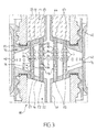
- a system for diffusing a fragrance comprises a device for diffusing a fragrance 20 and two bottles 12, 14 mounted head to tail, of which only the respective necks 12a, 14a are shown.
- the system 10 is represented in its entirety at the figure 6 with the configuration of the figure 2 .
- the following description of figures 1 , 2 and 6 does not depend on a particular configuration such as that of the figure 2 .
- a first upper bottle 12 containing the fragrance (eg a room fragrance) to be diffused is mounted in the inverted position above the device 20 with its neck 12a facing downwards.
- the fragrance eg a room fragrance
- the device 20 comprises first fixing means 22 which are intended to fix the neck 12a to said device.
- These fixing means are for example made in the form of an internal thread 22a for screwing with the external thread 12b on the outer surface of the neck 12a.
- a second lower bottle 14 for recovering the non-diffused fragrance from the upper bottle 12 is mounted under the device 20 with its neck 14a facing upwards.
- the diffusion device 20 comprises second means of fixing 24 which are intended to fix the neck 14a to said device.
- These fixing means are for example made in the form of an internal thread 24a for screwing with the external thread 14b on the outer surface of the neck 14a.
- Other fastening means such as snap-fastening can be envisaged.
- the system 10 and its device 20 as well as the two flasks are arranged vertically on the figure 1 so that the fragrance contained in the upper bottle 12 can flow by gravity.
- the device 20 comprises two parts, namely an upper part 26 and a lower part 28 disposed opposite and spaced from each other along a longitudinal axis L which here is oriented vertically.
- the two parts 26, 28 each comprise a wall 30, 32 disposed vis-à-vis one another and defining between them, along the longitudinal axis L, a central cavity C.
- the walls 30, 32 extend transversely from their central region towards their periphery, at the level of which axially extends a wall 36, 38.
- the two axially extending walls 36, 38 of the parts 26, 28 extend in opposite directions and away from the cavity C.
- the fixing means 22, 24 are arranged on the inner surface of these walls. Note that the neck 12a, 14a of each bottle, once attached to the device 20, abuts against a respective joint J1, J2 arranged in a recess of the outer face 30a, 32a of the transverse extension wall considered.
- each transverse wall 30, 32 has a generally concave shape whose concavity is oriented towards the cavity C.
- Each wall has more particularly a funnel-shaped converging towards the central region.
- Each piece 26, 28 generally presents a symmetry of axial revolution to a few details of implementation.
- the axial extension walls 36, 38 each have a substantially cylindrical shape conferring them a skirt shape.
- the device 20 also comprises at its periphery a peripheral wall 40 having a general shape of a ring surrounding the assembly formed by the two parts 26, 28 facing each other and the central separating cavity C.
- This peripheral wall 40 forms a trim piece and is fixed on each of the aforementioned sets for example by gluing, welding or other suitable means.
- the peripheral wall 40 is provided with at least one opening 42 for diffusing fragrance outside the device.
- Said at least one opening 42 is made in the region of the wall which is located around the cavity C so as to put this cavity in communication with the outside of the device.
- a plurality of openings 42 are disposed around the perimeter of the peripheral wall 40 as shown in FIG. figure 1 , in an equatorial region of the device.
- Each of the transverse extension walls 30, 32 comprises a plurality of through-openings respectively denoted O1, 02 which each put in communication with the cavity C an area external to the device, denoted respectively Z1, Z2, and adjacent to the wall. concerned, 30, 32.
- each external zone Z1, Z2 is an area inside the neck of a bottle.
- the figure 2 represents another possible example of distribution of the openings O1 in the wall 30.
- the openings are arranged in series which each group several openings, the series being arranged in a radial arrangement.
- Other alternative configurations can be used (eg provision in concentric crowns ..).
- the openings disposed in the upper wall are dimensioned to allow them to pass through fragrance drops G from the zone Z1 and fall inside the cavity as shown in FIG. figure 1 .
- the multitude of openings perforating the wall ensures a given diffusion capacity. This parameter depends on the intended applications.
- each opening O1, 02 is extended on the side of the internal face 30b, 32b of the wall 30, 32 by a collar respectively noted c1, c2 and which projects into the cavity relative to the wall concerned.
- This configuration makes it possible to prevent the openings from becoming clogged when the drops of fragrance fall on the wall 32 which acts as a collector (or on the wall 30 when the latter is in turn below and then acts collector).
- the openings O1 and 02 of the two facing walls 30, 32 are not facing each other but offset transversely to reduce the risk of clogging in case of drop drops on the lower openings.
- Each of the transversely extending walls 30, 32 also comprises a duct 44, 46, respectively, arranged in the central region of the wall (at the bottom of the concavity) and passing through the latter so as to bring into communication the adjacent zone concerned ( Z1, Z2) with the cavity C. More particularly, each duct 44, 46 extends longitudinally (here vertically) in the adjacent area concerned in the manner of a chimney.
- the upper duct 44 extends inside the upper flask 12 to a height sufficient for the open end 44a of the upper duct 44 to always be above the level of the liquid fragrance L1 contained in the zone Z1 ( figure 6 ). It is the same with the conduit 46 when the device is reversed and becomes an upper conduit.
- the open end of the conduit 44 has not been extended as on the figure 6 for the sake of simplification.
- Each duct opens, at its end which is opposite the open end, at the inner face 30b, 32b of the relevant wall without projecting into the cavity.
- the openings O1 and O2 therefore respectively surround the conduits 44 and 46.
- the upper duct 44 serves as a return air duct which takes directly air from outside the device via the openings 42 and not the bottom flask.
- This arrangement is more efficient because it is less sensitive to pressure variations from one bottle to another. These pressure variations can be, for example, generated when the top bottle is exposed to the sun behind a window and the bottom one in the shade, or the opposite, or when the bottom bottle is placed on a radiator while the upper one is exposed to a current of cold air. Temperature changes affect pressures by the dilation effect of alcoholic bases that are present in perfumes. In the device according to the invention, the return air is in stable pressure since it comes from outside.
- the conduit is dimensioned (in particular by its diameter) to allow a drop of fragrance in the cavity which is adapted to the number of openings of the wall and to their diameter and which is satisfactory in terms of diffusion power (ability to diffuse odorant molecules in the air).
- the flow rate and therefore the drip depends in particular on the ability of the device to take air.
- the lower duct 46 recovers the dropped drops on the inclined wall 32 and conveyed by gravity until duct.
- the duct 46 (penetrates into the lower bottle 14) thus ensures the flow of fragrance in the zone Z2 and in the lower bottle of the fragrance which has not been diffused.
- the liquid (fragrance) present in the zone Z1 of the upper flask 12 returned passes through the openings O1, then forms drops G escaping from said openings.
- the drops drop by gravity inside the cavity over the entire height of the latter and explode upon reaching the bottom wall 32 of the collector.
- the diffusion of the fragrance is thus effected during the fall of the drops but mainly during the bursting of the drops on the wall 32.
- the diffusion takes place radially or transversely in the air which is present inside the cavity C (diffusion zone), then through the openings 42 to exit the device 20.
- the drip thus formed in the cavity creates a sort of suction of the liquid from the bottle 12 and therefore a vacuum in said bottle (pumping effect). This depression is compensated by the external air that enters the bottle through the air intake duct 44.
- the collector walls 30 and 32 are inclined towards their central region (bottom of the concavity) in order to be able to collect the liquid in the central duct 46. This also allows the openings 02 present in the wall 32 (the same reasoning is not possible). applied with the openings O1 present in the wall 30 when the system is returned) are disposed at an altitude higher than that of a low point of the wall surrounding the conduit 46 and around which liquid could accumulate. Such an arrangement greatly reduces the risk that liquid collected by the wall 32 will obstruct the openings 02 during operation of the system.
- air intake ducts 44 can be arranged on the wall 30 (respectively 32).
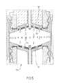
- the figure 3 represents a diffusion system of a fragrance 60 according to a second embodiment of the invention.
- This system 60 comprises a device for diffusing a fragrance 70 which differs mainly from the device 20 of the figure 1 by the presence of obstacles or bodies deviating the flow of liquid fragrance inside the cavity C such as tubes.
- the upper 72 and lower concave walls 74, inclined towards the inlet of each respective duct 44, 46, are also provided with openings O'1, O'2 through the wall concerned in its thickness, so as to allow the formation and passage of drops of the adjacent zone Z1, Z2 to the cavity.
- tubes 76 extend longitudinally inside the cavity, each between two openings O'1 and O'2 which are located vis-à-vis one another and which are connected by a tube.
- Each tube is for example inserted through its two opposite ends respectively in the two openings O'1 and O'2 in correspondence.
- the tubes can be attached to the relevant wall without being introduced into the openings.
- Each tube 76 is hollow and has a cylindrical wall 78 which is pierced with a plurality of lateral orifices 80 which communicate the interior of the tube and the cavity.
- the tube 76 is separated into two compartments or elongated chambers 82, 84, arranged one above the other and separated from each other by a transverse partition 86, for example at mid-height of the tube.
- the first compartment 82 communicates with the opening O'1 and the second compartment 84 communicates with the opening O'2.
- the lateral orifices 80 which are located lowest in the first compartment 82 are preferably arranged at a distance from the separating partition 86 so as to provide between them a space which can be filled with liquid (buffer volume).
- the liquid flows through the openings O'1 and enters the first compartments 82 of each tube.
- the liquid accumulates by gravity in the aforementioned space until reaching the lowest holes 80 and out of the tubes by the latter. If the volume of liquid is larger, the compartment 82 fills further until reaching the upper ports 80 and out through them.
- the section of the lateral orifices 80 and the internal section of the compartments 82, 84 is suitably sized for the purpose pursued. Thus, for example, if one chooses very small sections for the lateral orifices 80, the liquid can go up into the compartment 82 of larger section and fill up to the top. In this case, it is the section of the lateral orifices 80 which defines the speed flow of the perfume into the cavity.
- the tubes 76 and the bottom wall 74 act as liquid collectors.
- the tubes 76 form baffles for the flow of liquid from the openings O'1, thus slowing down this flow and therefore the phenomenon of drip. It follows that the passage time (flow) of the drops inside the cavity is increased, which makes it possible to increase the diffusion time and the diffusion capacity of the device. The management of the diffusion time can be controlled. by appropriately selecting the number of tubes 76 and their cross section.
- the two compartment arrangement described above is easily cleanable in that the two compartments are accessible by their respective open ends.
- the figure 4 is a schematic view in axial section of a fragrance diffusion device 100 which artificially integrates several different types of obstacles or flow deflection bodies (flow retardant elements) and which constitute variants of the flow tubes; the figure 3 .
- a device 100 may very well comprise only one type of flow retardant element.
- the elements have the function of retaining as long as possible in the cavity C (diffusion chamber) the liquid flowing from the upper flask by deflecting its trajectory along different simultaneous paths. The drops flow along these elements and stay on even if the device is returned (limitation of sagging).
- These elongate members are mounted at their opposite upper and lower ends in the corresponding walls 72 and 74.
- the figure 5 illustrates a device 110 according to an alternative embodiment of the device of the figure 1 .
- elements of absorbent material 112, 114 eg felt pellet
- the walls 30, 32 collectors
- the liquid is retained by the absorbent material and therefore does not flood the cavity (strong limitation of sagging).
- liquid perfume
- absorbent material delaying effect of the elements
Landscapes
- Health & Medical Sciences (AREA)
- Epidemiology (AREA)
- Life Sciences & Earth Sciences (AREA)
- Animal Behavior & Ethology (AREA)
- General Health & Medical Sciences (AREA)
- Public Health (AREA)
- Veterinary Medicine (AREA)
- Disinfection, Sterilisation Or Deodorisation Of Air (AREA)
Applications Claiming Priority (1)
| Application Number | Priority Date | Filing Date | Title |
|---|---|---|---|
| FR1450072A FR3016129B1 (fr) | 2014-01-07 | 2014-01-07 | Dispositif de diffusion d'une fragrance avec une multitude d'ouvertures |
Publications (1)
| Publication Number | Publication Date |
|---|---|
| EP2905035A1 true EP2905035A1 (de) | 2015-08-12 |
Family
ID=50976754
Family Applications (1)
| Application Number | Title | Priority Date | Filing Date |
|---|---|---|---|
| EP15150377.8A Withdrawn EP2905035A1 (de) | 2014-01-07 | 2015-01-07 | Vorrichtung zur Zerstäubung eines Duftstoffs mit einer Vielzahl von Öffnungen |
Country Status (3)
| Country | Link |
|---|---|
| US (1) | US20150190542A1 (de) |
| EP (1) | EP2905035A1 (de) |
| FR (1) | FR3016129B1 (de) |
Cited By (1)
| Publication number | Priority date | Publication date | Assignee | Title |
|---|---|---|---|---|
| FR3091998A1 (fr) * | 2019-01-26 | 2020-07-31 | Yacine Ouerdani | Appareil pour infuser/aromatiser/parfumer/maturer tous produits |
Families Citing this family (6)
| Publication number | Priority date | Publication date | Assignee | Title |
|---|---|---|---|---|
| CN109641074B (zh) * | 2016-05-27 | 2021-05-04 | 庆熙大学校产学协力团 | 香气扩散模块及包含所述模块的香气扩散容器 |
| US10279067B2 (en) * | 2016-10-12 | 2019-05-07 | Hya-scent, Inc. | Scent glass |
| USD980964S1 (en) | 2017-10-12 | 2023-03-14 | Hya-scent, Inc. | Fragrance diffuser element |
| USD869630S1 (en) | 2017-10-12 | 2019-12-10 | Hya-scent, Inc. | Fragrance diffuser element |
| USD894362S1 (en) * | 2017-10-12 | 2020-08-25 | Hya-scent, Inc. | Fragrance diffuser |
| ES2836906A1 (es) * | 2019-12-27 | 2021-06-28 | Zobele Espana Sa | Dispositivo de difusión de sustancias volátiles |
Citations (3)
| Publication number | Priority date | Publication date | Assignee | Title |
|---|---|---|---|---|
| DE676131C (de) * | 1935-06-15 | 1939-05-26 | Johann Witulla | Luftreinigungsvorrichtung |
| US20070176015A1 (en) * | 2006-01-30 | 2007-08-02 | The Procter & Gamble Company | System for delivering volatile materials |
| FR2958854A1 (fr) | 2010-04-16 | 2011-10-21 | Techniplast | Diffuseur de fragrance a retournement |
Family Cites Families (2)
| Publication number | Priority date | Publication date | Assignee | Title |
|---|---|---|---|---|
| US20060231641A1 (en) * | 2005-04-14 | 2006-10-19 | Hirotaka Uchiyama | Devices with anti-leak features for delivering volatile materials |
| EP1849485A1 (de) * | 2006-04-26 | 2007-10-31 | Boehringer Ingelheim microParts GmbH | Vorrichtung und Verfahren zum Verdunsten einer Flüssigkeit und Verdampfer |
-
2014
- 2014-01-07 FR FR1450072A patent/FR3016129B1/fr not_active Expired - Fee Related
-
2015
- 2015-01-07 US US14/591,270 patent/US20150190542A1/en not_active Abandoned
- 2015-01-07 EP EP15150377.8A patent/EP2905035A1/de not_active Withdrawn
Patent Citations (3)
| Publication number | Priority date | Publication date | Assignee | Title |
|---|---|---|---|---|
| DE676131C (de) * | 1935-06-15 | 1939-05-26 | Johann Witulla | Luftreinigungsvorrichtung |
| US20070176015A1 (en) * | 2006-01-30 | 2007-08-02 | The Procter & Gamble Company | System for delivering volatile materials |
| FR2958854A1 (fr) | 2010-04-16 | 2011-10-21 | Techniplast | Diffuseur de fragrance a retournement |
Cited By (1)
| Publication number | Priority date | Publication date | Assignee | Title |
|---|---|---|---|---|
| FR3091998A1 (fr) * | 2019-01-26 | 2020-07-31 | Yacine Ouerdani | Appareil pour infuser/aromatiser/parfumer/maturer tous produits |
Also Published As
| Publication number | Publication date |
|---|---|
| FR3016129B1 (fr) | 2017-07-21 |
| US20150190542A1 (en) | 2015-07-09 |
| FR3016129A1 (fr) | 2015-07-10 |
Similar Documents
| Publication | Publication Date | Title |
|---|---|---|
| EP2905035A1 (de) | Vorrichtung zur Zerstäubung eines Duftstoffs mit einer Vielzahl von Öffnungen | |
| EP2558131B1 (de) | Duftstoff-umkehrzerstäuber | |
| BE1004033A3 (fr) | Dispositif modulaire de distribution, destine a la distribution d'un courant de gaz, de preference dans un reacteur catalytique. | |
| FR2694215A1 (fr) | Appareil pour générer un brouillard à partir d'un liquide, notamment un médicament. | |
| FR2514479A1 (fr) | Echangeur de chaleur a circulation de liquide, en particulier pour un vehicule automobile | |
| FR3065171A1 (fr) | Dispositif de double distribution de liquide utile dans une colonne de fractionnement ou de lavage sur un support flottant | |
| FR2929858A1 (fr) | Filtre a carburant et cartouche filtrante permettant un degazage | |
| EP3027231B1 (de) | Vorrichtung zur diffusion von duftstoffen wie z. b. parfümen | |
| EP0366652B1 (de) | Schaumerzeuger und -ausgabevorrichtung | |
| EP1287211B1 (de) | Versorgungsflüssigkeitsspender für toilettenbecken | |
| EP1704289A1 (de) | Flüssigkeitsevakuierungsvorrichtung und entsprechende flüssigkeitsführungsvorrichtung | |
| EP3572039A1 (de) | Vorrichtung zum auffangen von tiersperma | |
| FR2802481A1 (fr) | Dispositif de mise a l'air libre d'un reservoir de carburant | |
| EP0022391B1 (de) | Gegenüber Beschleunigungen beständige kryostatische Vorrichtung | |
| EP0290339B1 (de) | Wärmetauscher mit Flüssigkeitszirkulation, insbesondere für Kraftwagen, und mit Entgasungskanal | |
| EP2054666A1 (de) | Brenner: katalytischer verbrenner mit spezialspitze und mit einem solchen brenner ausgestattete flasche | |
| FR2564743A3 (fr) | Dispositif d'amenee pour une installation de repartition uniforme d'un liquide dans des evaporateurs a cascade | |
| US11141503B2 (en) | Device for diffusing a fragrance, such as a scent | |
| EP4426499B1 (de) | Ansaugkappe für eine vorrichtung zur abgabe eines flüssigen produkts | |
| FR2527937A1 (fr) | Dispositif d'absorption d'un gaz tel que nh3, so2 ou la vapeur d'eau, par un liquide tel que l'eau | |
| EP3917310B1 (de) | Vorrichtung zur lagerung von unterzutauchenden produkten, ihre verwendung und entsprechende lagerungsanordnung | |
| EP3572038A1 (de) | Vorrichtung zum sammeln von tiersamen | |
| EP4671638A1 (de) | Flüssigkeitseinspritzstock und behälter mit mindestens einem solchen stock | |
| FR2516500A1 (fr) | Installation pour l'obtention de gouttes de verre a partir d'un verre fondu contenant des dechets radioactifs | |
| EP1674805A1 (de) | Kessel mit Verdrängungskörper mit Schalen im Rauchgasrohr |
Legal Events
| Date | Code | Title | Description |
|---|---|---|---|
| PUAI | Public reference made under article 153(3) epc to a published international application that has entered the european phase |
Free format text: ORIGINAL CODE: 0009012 |
|
| AK | Designated contracting states |
Kind code of ref document: A1 Designated state(s): AL AT BE BG CH CY CZ DE DK EE ES FI FR GB GR HR HU IE IS IT LI LT LU LV MC MK MT NL NO PL PT RO RS SE SI SK SM TR |
|
| AX | Request for extension of the european patent |
Extension state: BA ME |
|
| STAA | Information on the status of an ep patent application or granted ep patent |
Free format text: STATUS: THE APPLICATION IS DEEMED TO BE WITHDRAWN |
|
| 18D | Application deemed to be withdrawn |
Effective date: 20160213 |