EP2904987A1 - Dampening insert for dental implants - Google Patents
Dampening insert for dental implants Download PDFInfo
- Publication number
- EP2904987A1 EP2904987A1 EP14154628.3A EP14154628A EP2904987A1 EP 2904987 A1 EP2904987 A1 EP 2904987A1 EP 14154628 A EP14154628 A EP 14154628A EP 2904987 A1 EP2904987 A1 EP 2904987A1
- Authority
- EP
- European Patent Office
- Prior art keywords
- insert
- implant
- superstructure
- screw
- profile
- Prior art date
- Legal status (The legal status is an assumption and is not a legal conclusion. Google has not performed a legal analysis and makes no representation as to the accuracy of the status listed.)
- Granted
Links
Images




Classifications
-
- A—HUMAN NECESSITIES
- A61—MEDICAL OR VETERINARY SCIENCE; HYGIENE
- A61C—DENTISTRY; APPARATUS OR METHODS FOR ORAL OR DENTAL HYGIENE
- A61C8/00—Means to be fixed to the jaw-bone for consolidating natural teeth or for fixing dental prostheses thereon; Dental implants; Implanting tools
- A61C8/0048—Connecting the upper structure to the implant, e.g. bridging bars
- A61C8/005—Connecting devices for joining an upper structure with an implant member, e.g. spacers
- A61C8/0068—Connecting devices for joining an upper structure with an implant member, e.g. spacers with an additional screw
-
- A—HUMAN NECESSITIES
- A61—MEDICAL OR VETERINARY SCIENCE; HYGIENE
- A61C—DENTISTRY; APPARATUS OR METHODS FOR ORAL OR DENTAL HYGIENE
- A61C8/00—Means to be fixed to the jaw-bone for consolidating natural teeth or for fixing dental prostheses thereon; Dental implants; Implanting tools
- A61C8/0086—Means to be fixed to the jaw-bone for consolidating natural teeth or for fixing dental prostheses thereon; Dental implants; Implanting tools with shock absorbing means
-
- A—HUMAN NECESSITIES
- A61—MEDICAL OR VETERINARY SCIENCE; HYGIENE
- A61C—DENTISTRY; APPARATUS OR METHODS FOR ORAL OR DENTAL HYGIENE
- A61C13/00—Dental prostheses; Making same
- A61C13/10—Fastening of artificial teeth to denture palates or the like
- A61C13/1003—Fastening of artificial teeth to denture palates or the like by embedding in base material
-
- A—HUMAN NECESSITIES
- A61—MEDICAL OR VETERINARY SCIENCE; HYGIENE
- A61C—DENTISTRY; APPARATUS OR METHODS FOR ORAL OR DENTAL HYGIENE
- A61C8/00—Means to be fixed to the jaw-bone for consolidating natural teeth or for fixing dental prostheses thereon; Dental implants; Implanting tools
- A61C8/0012—Means to be fixed to the jaw-bone for consolidating natural teeth or for fixing dental prostheses thereon; Dental implants; Implanting tools characterised by the material or composition, e.g. ceramics, surface layer, metal alloy
- A61C8/0016—Means to be fixed to the jaw-bone for consolidating natural teeth or for fixing dental prostheses thereon; Dental implants; Implanting tools characterised by the material or composition, e.g. ceramics, surface layer, metal alloy polymeric material
-
- A—HUMAN NECESSITIES
- A61—MEDICAL OR VETERINARY SCIENCE; HYGIENE
- A61C—DENTISTRY; APPARATUS OR METHODS FOR ORAL OR DENTAL HYGIENE
- A61C8/00—Means to be fixed to the jaw-bone for consolidating natural teeth or for fixing dental prostheses thereon; Dental implants; Implanting tools
- A61C8/0048—Connecting the upper structure to the implant, e.g. bridging bars
- A61C8/005—Connecting devices for joining an upper structure with an implant member, e.g. spacers
- A61C8/0074—Connecting devices for joining an upper structure with an implant member, e.g. spacers with external threads
Definitions
- the present invention relates to an insert, in particular having a cushioning effect, for a dental prosthesis screwed onto an implant.
- the invention also relates to the dental prosthesis provided with this insert.
- the field of invention relates to dental prostheses screwed onto an implant, in which a superstructure is fixed, by means of a screw, onto the implant integrated in the bone.
- the fixing of a superstructure onto an implant is traditionally effected by direct contact between the parts, i.e. without any intermediate elements suitable for separating the respective contact surfaces. Any stress on the superstructure, generated in particular by mastication, is consequently discharged directly onto the implant and therefore also onto the bone sustaining it.
- the stress peaks transmitted onto the contact surface between the bone and the implant are, however, particularly detrimental as they can cause the detachment of the implant from its seat and consequently instability of the prosthesis, with a possible loss of the implant.
- An objective of the present invention is to provide a dental prosthesis which is similar to the natural state of the tooth, in which the stress peaks are damped before being discharged onto the bone.
- a further objective of the present invention is to provide a prosthesis suitable for preventing the stress peaks received by the superstructures from reaching the bone unaltered.
- Another objective of the invention is to provide a prosthesis suitable for preventing infiltrations of bacteria between the surfaces in reciprocal contact, of the implant and superstructure, respectively.
- Yet another objective of the invention to protect the surface of the dental superstructure in contact with the implant, thus avoiding possible damage due to the reciprocal fixing operations between these parts, and movements caused by mastication.
- the insert of the invention comprises a superstructure and an implant integrated in the bone, which are reciprocally joined by means of a screw, wherein said insert consists of an element made of a damping material interposed between the coupling surfaces of the superstructure and implant, respectively.
- said insert consists of an element having an annular shape provided with a hole for the passage of the above-mentioned screw.
- the insert of the invention consists of an element containing a base suitable for being interposed between the above-mentioned coupling surfaces, said insert also having a profile which is engaged with the coupling section between the superstructure and the implant.
- the insert of the invention is also characterized in that it consists of an element having an annular base suitable for being interposed between the above-mentioned coupling surfaces of the superstructure and implant, a profile which is engaged inside said superstructure and a threaded portion to be engaged with a cap, also threaded, for blocking said superstructure on the insert, said screw causing the fixing of the insert on the implant.
- the insert of the invention consists of an element having an annular base suitable for being interposed between the above-mentioned coupling surfaces and a profile which is engaged inside said above-mentioned superstructure, said screw having a conical portion which, when engaged inside the hole of the insert, causes the expansion of said profile, thus blocking the superstructure on the insert and on the implant.
- the insert of the invention is also characterized in that it comprises a protrusion suitable for being engaged with a corresponding housing of the superstructure, thus blocking its rotation on the same insert.
- the latter is particularly made of an elastically deformable plastic material which, when subjected to a preload of 10-50 Nm by means of said screw 5, in the presence of additional loads as those performed by the masticatory apparatus, undergoes an elastic deformation of 0,01-80 ⁇ (micron) in the direction of the vertical axis.
- a dental prosthesis is obtained, which is screwed onto an implant which reproduces the natural anchoring state of the tooth to the bone, so that the stress peaks on the superstructure are damped before being discharged onto the implant and consequently also onto the bone.
- the insert of the invention also offers the advantage of sealing the contact area between the superstructure and implant, thus preventing any dangerous infiltrations of bacteria.
- the prosthesis of the known art illustrated in figure 1 consists of a superstructure 2 fixed on the implant 3 anchored to the bone 4, by means of a screw 5, housed inside the hole 29 of the same superstructure 2.
- the surface 6 of the superstructure and the surface 7 of the implant are in direct contact with each other at the interface between the superstructure 2 and the implant 3.
- the stress peaks on the superstructure are therefore discharged directly, first onto the side surface 9 of the implant 3 and from there onto the surface 8 of the bone 4.
- the mentioned surfaces 8 and 9 can be reciprocally detached, thus causing a loss in the hold of the implant in its seat and requiring the re-establishment or re-implantation of the implant itself.
- this insert 12 substantially consists of a circular washer, having a central hole 13 for the passage of the screw 5 which blocks the superstructure 2 to the implant 3.
- the material of the insert 12 must be less rigid than those forming the superstructure (for example ceramic, titanium and chromium/cobalt alloys) and those used for the production of the implant (for example titanium).
- the formation material of the insert 12 is preferably an elastically deformable plastic material which, when subjected to a preload of 10-50 Nm by means of said screw 5, in the presence of additional loads as those exercised by the masticatory apparatus (generally up to 400N), undergoes an elastic deformation of 0,01-80 ⁇ (micron) in the direction of the vertical axis.
- the material forming the insert 12 must exhibit an elastic modulus sufficient to restore its initial geometry in the absence of the masticatory load.
- the insert 14 has an annular base 15 in a single piece, with a profile 16 which reproduces the form of the coupling section between the superstructure 2 and the implant 3.
- the annular base 15 of the insert 14 has the protective cushioning and damping functions already described with reference to the washer 12 of figures 3 and 4 , whereas the profile 16 acts as a damping and centering component between the implant 3 and the superstructure 2.
- the outer section of the profile 16 of the insert 14 advantageously has the form of the corresponding coupling section of the implant, thus also obtaining an anti-rotational effect.
- the insert 14 is positioned at the side of the inner connection 17 of the implant, and no longer externally such as that represented in figure 6 .
- the screw 5 joins the insert 18 to the implant 3, whereas, for the anchorage of the superstructure 2 to the insert 18 (and therefore also to the implant 3), a threaded cap 19 is used, which is screwed onto the corresponding threaded portion 20 of the insert 18.
- the insert 18 has an annular base 21, a profile 22 with the described threaded portion 20, and is also produced with the same material used for the inserts 12 and 14 previously described.
- the insert 18 of figure 14 advantageously has a protrusion 23 which, by engagement in a corresponding housing 24 inside the superstructure 2 of figure 11 , has an anti-rotational function between the same structure and the insert.
- a screw 25 is used for the reciprocal anchorage between the superstructure 2, the insert 27 and the implant 3, said screw having a conical portion 26, in turn suitable for being engaged inside the base 30, also having a corresponding conical form, of the hole 13 of the insert 27. Therefore, when the screw 25 is engaged inside the hole 13 of the insert 27, its profile 26 compresses the base 30 of the hole 13, thus expanding the outer profile 28 of the insert 27 against the corresponding inner surface of the hole 29 of the superstructure 2, thus blocking the superstructure without the necessity of the cap 19 of the version of figure 11 .
Landscapes
- Health & Medical Sciences (AREA)
- Oral & Maxillofacial Surgery (AREA)
- Epidemiology (AREA)
- Dentistry (AREA)
- Life Sciences & Earth Sciences (AREA)
- Animal Behavior & Ethology (AREA)
- General Health & Medical Sciences (AREA)
- Public Health (AREA)
- Veterinary Medicine (AREA)
- Orthopedic Medicine & Surgery (AREA)
- Ceramic Engineering (AREA)
- Engineering & Computer Science (AREA)
- Dental Prosthetics (AREA)
Abstract
Description
- The present invention relates to an insert, in particular having a cushioning effect, for a dental prosthesis screwed onto an implant. The invention also relates to the dental prosthesis provided with this insert.
- The field of invention relates to dental prostheses screwed onto an implant, in which a superstructure is fixed, by means of a screw, onto the implant integrated in the bone.
- The fixing of a superstructure onto an implant is traditionally effected by direct contact between the parts, i.e. without any intermediate elements suitable for separating the respective contact surfaces. Any stress on the superstructure, generated in particular by mastication, is consequently discharged directly onto the implant and therefore also onto the bone sustaining it. The stress peaks transmitted onto the contact surface between the bone and the implant are, however, particularly detrimental as they can cause the detachment of the implant from its seat and consequently instability of the prosthesis, with a possible loss of the implant.
- An objective of the present invention is to provide a dental prosthesis which is similar to the natural state of the tooth, in which the stress peaks are damped before being discharged onto the bone.
- A further objective of the present invention is to provide a prosthesis suitable for preventing the stress peaks received by the superstructures from reaching the bone unaltered.
- Another objective of the invention is to provide a prosthesis suitable for preventing infiltrations of bacteria between the surfaces in reciprocal contact, of the implant and superstructure, respectively.
- Yet another objective of the invention to protect the surface of the dental superstructure in contact with the implant, thus avoiding possible damage due to the reciprocal fixing operations between these parts, and movements caused by mastication.
- These and other objectives are achieved by means of the insert and prosthesis of
claims 1 and 9 respectively. Some preferred embodiments of the invention are described in the remaining claims. - In particular, the insert of the invention comprises a superstructure and an implant integrated in the bone, which are reciprocally joined by means of a screw, wherein said insert consists of an element made of a damping material interposed between the coupling surfaces of the superstructure and implant, respectively.
- According to the invention, said insert consists of an element having an annular shape provided with a hole for the passage of the above-mentioned screw.
- In particular, the insert of the invention consists of an element containing a base suitable for being interposed between the above-mentioned coupling surfaces, said insert also having a profile which is engaged with the coupling section between the superstructure and the implant.
- The insert of the invention is also characterized in that it consists of an element having an annular base suitable for being interposed between the above-mentioned coupling surfaces of the superstructure and implant, a profile which is engaged inside said superstructure and a threaded portion to be engaged with a cap, also threaded, for blocking said superstructure on the insert, said screw causing the fixing of the insert on the implant.
- According to a variant, the insert of the invention consists of an element having an annular base suitable for being interposed between the above-mentioned coupling surfaces and a profile which is engaged inside said above-mentioned superstructure, said screw having a conical portion which, when engaged inside the hole of the insert, causes the expansion of said profile, thus blocking the superstructure on the insert and on the implant.
- The insert of the invention is also characterized in that it comprises a protrusion suitable for being engaged with a corresponding housing of the superstructure, thus blocking its rotation on the same insert.
- The latter is particularly made of an elastically deformable plastic material which, when subjected to a preload of 10-50 Nm by means of said
screw 5, in the presence of additional loads as those performed by the masticatory apparatus, undergoes an elastic deformation of 0,01-80 µ (micron) in the direction of the vertical axis. - Thanks to the insert of the invention, a dental prosthesis is obtained, which is screwed onto an implant which reproduces the natural anchoring state of the tooth to the bone, so that the stress peaks on the superstructure are damped before being discharged onto the implant and consequently also onto the bone.
- The insert of the invention also offers the advantage of sealing the contact area between the superstructure and implant, thus preventing any dangerous infiltrations of bacteria.
- Again, thanks to the cushioning effect generated by the insert of the invention, made of a material suitable for the purpose, damage to the superstructure is prevented, due to contact of the same with the implant during the fixing operations between the parts and also during mastication.
- These and other objectives, advantages and characteristics are evident from the following description of some preferred embodiments of the insert and prosthesis of the invention, illustrated, as a nonlimiting example, in the figures of the enclosed drawings. In which:
-
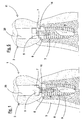
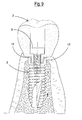
figure 1 illustrates a sectional view of a dental prosthesis screwed according to the known art; -
figure 2 illustrates a sectional view of a first embodiment of the dental prosthesis screwed according to the invention; -
figures 3 and 4 illustrate a plan and sectional view, respectively, of the insert assembled on the prosthesis offigure 2 ; -
figure 5 illustrates a variant of the prosthesis and insert offigures 2 to 4 ; -
figure 6 illustrates a detail of an anchorage for an implant having an external connection with the insert positioned between the superstructure and the implant of the prosthesis offigure 5 ; -
figures 7, 7a and 8 illustrate a perspective, plan and sectional view, respectively, of the insert assembled on the prosthesis offigure 6 ; -
figure 9 illustrates a detail of an anchorage for an implant having an internal connection, between the superstructure and the implant of the prosthesis of the invention; -
figure 10 illustrates a sectional view of a second embodiment of a screwed dental prosthesis of the invention, with an insert having a floating anchorage and retention cap of the superstructure; -
figure 11 illustrates an exploded view of the prosthesis offigure 10 ; -
figure 12 illustrates a sectional view of a third embodiment of a screwed dental prosthesis - according to the invention, with an insert having a floating anchorage and with retention of the superstructure with a conical coupling;
-
figure 13 illustrates an exploded view of the prosthesis offigure 12 ; and -
figure 14 illustrates a plan view of the insert of the prosthesis offigures 10 to 13 . - The prosthesis of the known art illustrated in
figure 1 , indicated as a whole with 1, consists of asuperstructure 2 fixed on theimplant 3 anchored to the bone 4, by means of ascrew 5, housed inside thehole 29 of thesame superstructure 2. In this embodiment, the surface 6 of the superstructure and thesurface 7 of the implant are in direct contact with each other at the interface between thesuperstructure 2 and theimplant 3. The stress peaks on the superstructure are therefore discharged directly, first onto theside surface 9 of theimplant 3 and from there onto thesurface 8 of the bone 4. As a result, the mentionedsurfaces - From
figure 1 , it can also be observed that, at the interface of the mentioned surfaces 6 of thesuperstructure implant 3, there are inevitablyinterspaces 10, normally due to the mechanical production tolerances of these parts. These interspaces have the disadvantage of representing seats for undesired and dangerous bacterial proliferation. - For the same reasons, the
same surfaces 6 and 7, in direct contact with each other, can be damaged by the stress of mastication. - All of these drawbacks are solved by means of the
prosthesis 11 offigure 2 , in which aninsert 12 is interposed between the facing surfaces 6 of thesuperstructure implant 3. As better illustrated infigures 3 and 4 , thisinsert 12 substantially consists of a circular washer, having acentral hole 13 for the passage of thescrew 5 which blocks thesuperstructure 2 to theimplant 3. - As a result of its damping and protective cushioning functions between the surfaces 6 of the
superstructure implant 3, the material of theinsert 12 must be less rigid than those forming the superstructure (for example ceramic, titanium and chromium/cobalt alloys) and those used for the production of the implant (for example titanium). - The formation material of the
insert 12 is preferably an elastically deformable plastic material which, when subjected to a preload of 10-50 Nm by means of saidscrew 5, in the presence of additional loads as those exercised by the masticatory apparatus (generally up to 400N), undergoes an elastic deformation of 0,01-80 µ (micron) in the direction of the vertical axis. To this purpose the material forming theinsert 12 must exhibit an elastic modulus sufficient to restore its initial geometry in the absence of the masticatory load. - In the embodiment of
figures 5 to 8 , theinsert 14 has anannular base 15 in a single piece, with aprofile 16 which reproduces the form of the coupling section between thesuperstructure 2 and theimplant 3. In this variant, theannular base 15 of theinsert 14 has the protective cushioning and damping functions already described with reference to thewasher 12 offigures 3 and 4 , whereas theprofile 16 acts as a damping and centering component between theimplant 3 and thesuperstructure 2. As illustrated infigure 7 , the outer section of theprofile 16 of theinsert 14, advantageously has the form of the corresponding coupling section of the implant, thus also obtaining an anti-rotational effect. As illustrated infigure 9 , theinsert 14 is positioned at the side of theinner connection 17 of the implant, and no longer externally such as that represented infigure 6 . - Unlike the prosthesis of
figures 2 to 5 , in which thescrew 5 is used for reciprocally fixing the superstructure, implant and insert, in the variant offigures 10 and 11 , thescrew 5 joins theinsert 18 to theimplant 3, whereas, for the anchorage of thesuperstructure 2 to the insert 18 (and therefore also to the implant 3), a threadedcap 19 is used, which is screwed onto the corresponding threadedportion 20 of theinsert 18. In this variant, as is better illustrated infigure 11 , theinsert 18 has anannular base 21, aprofile 22 with the described threadedportion 20, and is also produced with the same material used for theinserts insert 18 offigure 14 advantageously has aprotrusion 23 which, by engagement in acorresponding housing 24 inside thesuperstructure 2 offigure 11 , has an anti-rotational function between the same structure and the insert. - In the variant of
figures 12 and 13 , ascrew 25 is used for the reciprocal anchorage between thesuperstructure 2, theinsert 27 and theimplant 3, said screw having aconical portion 26, in turn suitable for being engaged inside thebase 30, also having a corresponding conical form, of thehole 13 of theinsert 27. Therefore, when thescrew 25 is engaged inside thehole 13 of theinsert 27, itsprofile 26 compresses thebase 30 of thehole 13, thus expanding theouter profile 28 of theinsert 27 against the corresponding inner surface of thehole 29 of thesuperstructure 2, thus blocking the superstructure without the necessity of thecap 19 of the version offigure 11 . - Having thus described some preferred exemplary embodiments of the device of the present invention in accordance with the principles of the present invention, it should be apparent to those skilled in the art that various additional objects and advantages have been attained by the invention and that a variety of modifications can be made within the scope of the present invention, being limited by the following appended claims only.
Claims (9)
- An insert for a dental prosthesis screwed onto an implant, in particular of the type comprising a superstructure (2) and an implant (3) integrated in the bone (4), which are reciprocally joined by means of a screw (5,25), characterized in that it consists of an element made of a damping material, interposed between the coupling surfaces (6,7) of the superstructure (2) and implant (3), respectively.
- The insert according to claim 1, characterized in that it consists of an element (12) having an annular form, provided with a hole (13) for the passage of said screw (5).
- The insert according to claim 1, characterized in that it consists of an element (14) having a base (15) suitable for being interposed between the mentioned surfaces (6,7) said insert also having a profile (16) which is engaged on the coupling section between the superstructure (2) and the implant (3).
- The insert according to claim 1, characterized in that it consists of an element (18) having an annular base (21) suitable for being interposed between the mentioned surfaces (6,7), a profile (22) which is engaged inside the superstructure (2) and a threaded portion (20) for engagement with a cap (19), also threaded, for blocking the superstructure (2) on the insert (18), said screw (5) fixing the insert (18) onto the implant (3).
- The insert according to claim 1, characterized in that it consists of an element (27) having an annular base suitable for being interposed between the mentioned surfaces (6,7) and a profile (28) which is engaged inside the superstructure (2), said screw (25) having a conical portion (26) which, when engaged inside the hole (13) of the insert (27), causes the expansion of said profile (28), thus blocking the superstructure (2) on the insert (27) and on the implant (3).
- The insert according to one or more of the previous claims, characterized in that it also comprises a protrusion (23) suitable for being engaged with a corresponding housing (24) of the superstructure (2), blocking its rotation on the same insert.
- The insert according to one or more of the previous claims, characterized in that it is made of an elastically deformable plastic material which, when subjected to a preload of 10-50 Nm by means of said screw (5), in the presence of additional loads as those performed by the masticatory apparatus, undergoes an elastic deformation in the direction of the vertical axis.
- The insert according to one or more of the previous claims, characterized in that the elastic deformation of the elastically deformable plastic material is 0,01 to 80 µ (micron), in particular 0,05 to 40 µ, preferred 0,1 to 20 µ in the direction of the vertical axis.
- A dental prosthesis, characterized in that it is a dental prosthesis screwed onto an implant according to one or more of the previous claims.
Priority Applications (5)
| Application Number | Priority Date | Filing Date | Title |
|---|---|---|---|
| EP14154628.3A EP2904987B1 (en) | 2014-02-11 | 2014-02-11 | Dental prosthesis with dampening insert |
| PCT/EP2015/000098 WO2015120954A1 (en) | 2014-02-11 | 2015-01-16 | Dampening insert for dental implants |
| CN201580007896.9A CN105979906A (en) | 2014-02-11 | 2015-01-16 | Dampening insert for dental implants |
| JP2016543229A JP2017505653A (en) | 2014-02-11 | 2015-01-16 | Buffer insert for dental implant |
| US15/107,446 US9918809B2 (en) | 2014-02-11 | 2015-01-16 | Dampening insert for dental implants |
Applications Claiming Priority (1)
| Application Number | Priority Date | Filing Date | Title |
|---|---|---|---|
| EP14154628.3A EP2904987B1 (en) | 2014-02-11 | 2014-02-11 | Dental prosthesis with dampening insert |
Publications (2)
| Publication Number | Publication Date |
|---|---|
| EP2904987A1 true EP2904987A1 (en) | 2015-08-12 |
| EP2904987B1 EP2904987B1 (en) | 2018-12-19 |
Family
ID=50072961
Family Applications (1)
| Application Number | Title | Priority Date | Filing Date |
|---|---|---|---|
| EP14154628.3A Active EP2904987B1 (en) | 2014-02-11 | 2014-02-11 | Dental prosthesis with dampening insert |
Country Status (5)
| Country | Link |
|---|---|
| US (1) | US9918809B2 (en) |
| EP (1) | EP2904987B1 (en) |
| JP (1) | JP2017505653A (en) |
| CN (1) | CN105979906A (en) |
| WO (1) | WO2015120954A1 (en) |
Cited By (1)
| Publication number | Priority date | Publication date | Assignee | Title |
|---|---|---|---|---|
| US12303351B2 (en) | 2017-07-07 | 2025-05-20 | Maló Clinic | Dental prosthesis |
Families Citing this family (10)
| Publication number | Priority date | Publication date | Assignee | Title |
|---|---|---|---|---|
| DE102016102009A1 (en) * | 2016-02-04 | 2017-08-10 | Holger Zipprich | Abutment, in particular for use with a dental implant inserted into the jawbone of a patient, and method of making the abutment |
| EP3335666B1 (en) | 2016-12-15 | 2021-03-10 | Ivoclar Vivadent AG | Device for holding an arrangement made of a superstructure and abutment |
| WO2018175026A1 (en) * | 2017-03-22 | 2018-09-27 | Alan Brown | Dental implant system |
| EP3520730A1 (en) * | 2018-02-02 | 2019-08-07 | VITA-ZAHNFABRIK H. Rauter GmbH & Co. KG | Holding device for tooth replacement elements |
| CN112638313B (en) * | 2018-08-27 | 2022-06-28 | Tri牙种植体国际股份公司 | Dental prosthesis |
| EP3711786A1 (en) * | 2019-03-19 | 2020-09-23 | Abiomed Europe GmbH | Blood pump |
| EP3711787A1 (en) * | 2019-03-19 | 2020-09-23 | Abiomed Europe GmbH | Blood pump |
| EP4082476A1 (en) | 2021-04-30 | 2022-11-02 | VITA-ZAHNFABRIK H. Rauter GmbH & Co. KG | Dental implant system |
| KR102480666B1 (en) * | 2022-04-22 | 2022-12-27 | 이노덴 주식회사 | Implant abutment for absorbing external shock in response to bite force and manufacturing methdo therof |
| US11950980B1 (en) * | 2023-08-18 | 2024-04-09 | Kwang Seob Kim | Tooth implant system |
Citations (6)
| Publication number | Priority date | Publication date | Assignee | Title |
|---|---|---|---|---|
| US4756689A (en) * | 1985-09-16 | 1988-07-12 | Dan Lundgren | Connecting devices |
| DE8905201U1 (en) * | 1989-04-25 | 1989-09-07 | Kanth, Lothar, 7800 Freiburg | Coronal intramobile element |
| EP0370590A2 (en) * | 1988-11-24 | 1990-05-30 | IMZ-Fertigungs- und Vertriebsgesellschaft für dentale Technologie mbH | Endosseous implant with elastic intermediate element and metal distance ring |
| US4993950A (en) * | 1988-06-20 | 1991-02-19 | Mensor Jr Merrill C | Compliant keeper system for fixed removable bridgework and magnetically retained overdentures |
| US5213500A (en) * | 1992-08-10 | 1993-05-25 | Alfred Salazar | Stress absorbing semipermanent dental implant system |
| DE10122151A1 (en) * | 2000-05-10 | 2001-11-15 | Physioplant S R L | Prosthetic dental appliance has support implant, bearing stay, blind recess, conical outer and inner part, shaft, connecting-head, cap and damping ring. |
Family Cites Families (28)
| Publication number | Priority date | Publication date | Assignee | Title |
|---|---|---|---|---|
| GB1341310A (en) * | 1971-09-30 | 1973-12-19 | Plessey Co Ltd | Artificial tooth structure |
| CH642838A5 (en) * | 1979-11-21 | 1984-05-15 | Osteo Ag | JAW IMPLANT. |
| JPS58116353A (en) * | 1981-12-17 | 1983-07-11 | 旭光学工業株式会社 | Upper structure of apatite artificial tooth root |
| US4416629A (en) * | 1982-07-06 | 1983-11-22 | Mozsary Peter G | Osseointerfaced implanted artificial tooth |
| US4552532A (en) * | 1983-12-12 | 1985-11-12 | Mozsary Peter G | Osteocorrective dentoalveolar implant system |
| DE3413811A1 (en) * | 1984-04-12 | 1985-10-31 | Ernst-Jürgen Dr. 5100 Aachen Richter | ARTIFICIAL DENTAL REPLACEMENT |
| DE3583399D1 (en) * | 1984-11-09 | 1991-08-08 | Implanto Lock Gmbh Fuer Implan | ENOSSAL IMPLANT FOR FIXING FIXED OR REMOVABLE DENTAL REPLACEMENT. |
| DE3531389A1 (en) * | 1985-09-03 | 1987-03-05 | Kirsch Axel | ENOSSAL IMPLANT |
| DE3615733A1 (en) * | 1986-05-09 | 1987-11-12 | Leitz Ernst Gmbh | TOOTH ROOT IMPLANT HIGH DURABILITY |
| US4842518A (en) * | 1986-09-04 | 1989-06-27 | Vent-Plant Corporation | Submergible screw-type dental implant and method of utilization |
| US4780080A (en) * | 1987-01-05 | 1988-10-25 | Facial Alveodental Implant Rehabilitation Inc. | Adjustable dentoalveolar implant system |
| DE3731265A1 (en) * | 1987-09-17 | 1989-03-30 | Richter Ernst Juergen Dr | CROWN FASTENING DEVICE FOR AN IMPLANT TO BE INSERTED IN A PINE |
| DE3841705C2 (en) * | 1988-12-10 | 1995-08-24 | Imz Fertigung Vertrieb | Endosseous implant |
| US5073111A (en) * | 1989-10-20 | 1991-12-17 | Fereidoun Daftary | Anatomical restoration dental implant system |
| US5040982A (en) * | 1990-06-28 | 1991-08-20 | Stefan Dogar Sorin | Dental implant and conversion assembly |
| JPH04250166A (en) * | 1990-09-19 | 1992-09-07 | Hoya Corp | Composite implant |
| US5302127A (en) * | 1993-06-01 | 1994-04-12 | Crisio Jr Raymond A | Dental implant stress stabilizer |
| US5527182A (en) * | 1993-12-23 | 1996-06-18 | Adt Advanced Dental Technologies, Ltd. | Implant abutment systems, devices, and techniques |
| US5954505A (en) * | 1998-03-05 | 1999-09-21 | Ford; Christopher W. | Force distributing dental implant |
| US6497573B2 (en) * | 1998-07-30 | 2002-12-24 | Centerpulse Dental Inc. | Composite dental abutment |
| US6939135B2 (en) * | 2002-06-03 | 2005-09-06 | Schubert L. Sapian | Growth factor releasing biofunctional dental implant |
| US7850452B2 (en) * | 2005-04-27 | 2010-12-14 | Biomet 3I, Llc | Pre-stressed implant component and assembly |
| WO2007109752A2 (en) * | 2006-03-22 | 2007-09-27 | Ascension Orthopedics, Inc. | Prosthetic implant and assembly method |
| ES2342800B1 (en) * | 2007-11-06 | 2011-04-28 | Enrique CANDEL AMOROS | ASSEMBLY OF INTERNAL CONNECTION DENTAL IMPLANT. |
| KR200448410Y1 (en) * | 2008-01-22 | 2010-04-09 | 주식회사 메가젠임플란트 | Abutments for dental implants |
| TWI487507B (en) * | 2012-05-07 | 2015-06-11 | Univ Nat Cheng Kung | Dental implant with cushion |
| EP2745802B1 (en) * | 2012-12-18 | 2018-03-21 | Kulzer GmbH | Hollow Superstructure for Dental Prostheses |
| CH708896A2 (en) * | 2013-11-27 | 2015-05-29 | Systems Schweiz Ag Z | Dental implant system with a ceramic implant. |
-
2014
- 2014-02-11 EP EP14154628.3A patent/EP2904987B1/en active Active
-
2015
- 2015-01-16 JP JP2016543229A patent/JP2017505653A/en active Pending
- 2015-01-16 US US15/107,446 patent/US9918809B2/en active Active
- 2015-01-16 CN CN201580007896.9A patent/CN105979906A/en active Pending
- 2015-01-16 WO PCT/EP2015/000098 patent/WO2015120954A1/en not_active Ceased
Patent Citations (6)
| Publication number | Priority date | Publication date | Assignee | Title |
|---|---|---|---|---|
| US4756689A (en) * | 1985-09-16 | 1988-07-12 | Dan Lundgren | Connecting devices |
| US4993950A (en) * | 1988-06-20 | 1991-02-19 | Mensor Jr Merrill C | Compliant keeper system for fixed removable bridgework and magnetically retained overdentures |
| EP0370590A2 (en) * | 1988-11-24 | 1990-05-30 | IMZ-Fertigungs- und Vertriebsgesellschaft für dentale Technologie mbH | Endosseous implant with elastic intermediate element and metal distance ring |
| DE8905201U1 (en) * | 1989-04-25 | 1989-09-07 | Kanth, Lothar, 7800 Freiburg | Coronal intramobile element |
| US5213500A (en) * | 1992-08-10 | 1993-05-25 | Alfred Salazar | Stress absorbing semipermanent dental implant system |
| DE10122151A1 (en) * | 2000-05-10 | 2001-11-15 | Physioplant S R L | Prosthetic dental appliance has support implant, bearing stay, blind recess, conical outer and inner part, shaft, connecting-head, cap and damping ring. |
Cited By (1)
| Publication number | Priority date | Publication date | Assignee | Title |
|---|---|---|---|---|
| US12303351B2 (en) | 2017-07-07 | 2025-05-20 | Maló Clinic | Dental prosthesis |
Also Published As
| Publication number | Publication date |
|---|---|
| US20160338802A1 (en) | 2016-11-24 |
| JP2017505653A (en) | 2017-02-23 |
| EP2904987B1 (en) | 2018-12-19 |
| WO2015120954A1 (en) | 2015-08-20 |
| US9918809B2 (en) | 2018-03-20 |
| CN105979906A (en) | 2016-09-28 |
Similar Documents
| Publication | Publication Date | Title |
|---|---|---|
| EP2904987B1 (en) | Dental prosthesis with dampening insert | |
| KR102323729B1 (en) | Dental implant system | |
| US6394808B2 (en) | Prosthetic device for intraosseous dental implants | |
| US10111735B2 (en) | Double-cushioned dental implant | |
| US9522053B2 (en) | Dental implant assembly for uniform distribution of occlusal forces | |
| KR102323728B1 (en) | Dental implant system | |
| JP6304895B2 (en) | Dental implant with cushion | |
| US10470851B2 (en) | Self-retaining dental screw | |
| KR200455126Y1 (en) | Implants to prevent screw loosening | |
| KR20200129837A (en) | Dental implant system | |
| KR100997553B1 (en) | One body implant | |
| US11529217B2 (en) | Dental implant | |
| KR102048180B1 (en) | Implant for artificial teeth with improved fixation structure and impact relaxation structure | |
| KR102638571B1 (en) | Detachable dental implant system | |
| KR102638899B1 (en) | Detachable dental implant system | |
| KR101597151B1 (en) | Dental implant | |
| KR101554392B1 (en) | Dental Implant | |
| KR20200129578A (en) | Self-locking device for Implant and the Abutment which is combined with the device | |
| KR102044664B1 (en) | Dental implant system | |
| KR101405293B1 (en) | Dental implant | |
| KR20250076233A (en) | Tissue level implant | |
| KR20230137576A (en) | Method for manufacturing alveolar bone damage prevention functional implant media | |
| KR20210020494A (en) | Implant | |
| ITMI20140065U1 (en) | DENTAL PROSTHETIC SYSTEM |
Legal Events
| Date | Code | Title | Description |
|---|---|---|---|
| PUAI | Public reference made under article 153(3) epc to a published international application that has entered the european phase |
Free format text: ORIGINAL CODE: 0009012 |
|
| AK | Designated contracting states |
Kind code of ref document: A1 Designated state(s): AL AT BE BG CH CY CZ DE DK EE ES FI FR GB GR HR HU IE IS IT LI LT LU LV MC MK MT NL NO PL PT RO RS SE SI SK SM TR |
|
| AX | Request for extension of the european patent |
Extension state: BA ME |
|
| 17P | Request for examination filed |
Effective date: 20160211 |
|
| RBV | Designated contracting states (corrected) |
Designated state(s): AL AT BE BG CH CY CZ DE DK EE ES FI FR GB GR HR HU IE IS IT LI LT LU LV MC MK MT NL NO PL PT RO RS SE SI SK SM TR |
|
| 17Q | First examination report despatched |
Effective date: 20160906 |
|
| STAA | Information on the status of an ep patent application or granted ep patent |
Free format text: STATUS: EXAMINATION IS IN PROGRESS |
|
| RAP1 | Party data changed (applicant data changed or rights of an application transferred) |
Owner name: KULZER GMBH |
|
| GRAP | Despatch of communication of intention to grant a patent |
Free format text: ORIGINAL CODE: EPIDOSNIGR1 |
|
| STAA | Information on the status of an ep patent application or granted ep patent |
Free format text: STATUS: GRANT OF PATENT IS INTENDED |
|
| INTG | Intention to grant announced |
Effective date: 20180718 |
|
| GRAS | Grant fee paid |
Free format text: ORIGINAL CODE: EPIDOSNIGR3 |
|
| GRAA | (expected) grant |
Free format text: ORIGINAL CODE: 0009210 |
|
| STAA | Information on the status of an ep patent application or granted ep patent |
Free format text: STATUS: THE PATENT HAS BEEN GRANTED |
|
| AK | Designated contracting states |
Kind code of ref document: B1 Designated state(s): AL AT BE BG CH CY CZ DE DK EE ES FI FR GB GR HR HU IE IS IT LI LT LU LV MC MK MT NL NO PL PT RO RS SE SI SK SM TR |
|
| REG | Reference to a national code |
Ref country code: GB Ref legal event code: FG4D |
|
| REG | Reference to a national code |
Ref country code: CH Ref legal event code: EP |
|
| REG | Reference to a national code |
Ref country code: IE Ref legal event code: FG4D |
|
| REG | Reference to a national code |
Ref country code: AT Ref legal event code: REF Ref document number: 1077860 Country of ref document: AT Kind code of ref document: T Effective date: 20190115 |
|
| REG | Reference to a national code |
Ref country code: DE Ref legal event code: R096 Ref document number: 602014038079 Country of ref document: DE |
|
| REG | Reference to a national code |
Ref country code: CH Ref legal event code: NV Representative=s name: PATENTANWAELTE SCHAAD, BALASS, MENZL AND PARTN, CH |
|
| REG | Reference to a national code |
Ref country code: SE Ref legal event code: TRGR |
|
| REG | Reference to a national code |
Ref country code: NL Ref legal event code: MP Effective date: 20181219 |
|
| PG25 | Lapsed in a contracting state [announced via postgrant information from national office to epo] |
Ref country code: LT Free format text: LAPSE BECAUSE OF FAILURE TO SUBMIT A TRANSLATION OF THE DESCRIPTION OR TO PAY THE FEE WITHIN THE PRESCRIBED TIME-LIMIT Effective date: 20181219 Ref country code: BG Free format text: LAPSE BECAUSE OF FAILURE TO SUBMIT A TRANSLATION OF THE DESCRIPTION OR TO PAY THE FEE WITHIN THE PRESCRIBED TIME-LIMIT Effective date: 20190319 Ref country code: HR Free format text: LAPSE BECAUSE OF FAILURE TO SUBMIT A TRANSLATION OF THE DESCRIPTION OR TO PAY THE FEE WITHIN THE PRESCRIBED TIME-LIMIT Effective date: 20181219 Ref country code: LV Free format text: LAPSE BECAUSE OF FAILURE TO SUBMIT A TRANSLATION OF THE DESCRIPTION OR TO PAY THE FEE WITHIN THE PRESCRIBED TIME-LIMIT Effective date: 20181219 Ref country code: NO Free format text: LAPSE BECAUSE OF FAILURE TO SUBMIT A TRANSLATION OF THE DESCRIPTION OR TO PAY THE FEE WITHIN THE PRESCRIBED TIME-LIMIT Effective date: 20190319 Ref country code: FI Free format text: LAPSE BECAUSE OF FAILURE TO SUBMIT A TRANSLATION OF THE DESCRIPTION OR TO PAY THE FEE WITHIN THE PRESCRIBED TIME-LIMIT Effective date: 20181219 |
|
| REG | Reference to a national code |
Ref country code: LT Ref legal event code: MG4D |
|
| REG | Reference to a national code |
Ref country code: AT Ref legal event code: MK05 Ref document number: 1077860 Country of ref document: AT Kind code of ref document: T Effective date: 20181219 |
|
| PG25 | Lapsed in a contracting state [announced via postgrant information from national office to epo] |
Ref country code: AL Free format text: LAPSE BECAUSE OF FAILURE TO SUBMIT A TRANSLATION OF THE DESCRIPTION OR TO PAY THE FEE WITHIN THE PRESCRIBED TIME-LIMIT Effective date: 20181219 Ref country code: RS Free format text: LAPSE BECAUSE OF FAILURE TO SUBMIT A TRANSLATION OF THE DESCRIPTION OR TO PAY THE FEE WITHIN THE PRESCRIBED TIME-LIMIT Effective date: 20181219 Ref country code: GR Free format text: LAPSE BECAUSE OF FAILURE TO SUBMIT A TRANSLATION OF THE DESCRIPTION OR TO PAY THE FEE WITHIN THE PRESCRIBED TIME-LIMIT Effective date: 20190320 |
|
| PG25 | Lapsed in a contracting state [announced via postgrant information from national office to epo] |
Ref country code: NL Free format text: LAPSE BECAUSE OF FAILURE TO SUBMIT A TRANSLATION OF THE DESCRIPTION OR TO PAY THE FEE WITHIN THE PRESCRIBED TIME-LIMIT Effective date: 20181219 |
|
| PG25 | Lapsed in a contracting state [announced via postgrant information from national office to epo] |
Ref country code: CZ Free format text: LAPSE BECAUSE OF FAILURE TO SUBMIT A TRANSLATION OF THE DESCRIPTION OR TO PAY THE FEE WITHIN THE PRESCRIBED TIME-LIMIT Effective date: 20181219 Ref country code: PT Free format text: LAPSE BECAUSE OF FAILURE TO SUBMIT A TRANSLATION OF THE DESCRIPTION OR TO PAY THE FEE WITHIN THE PRESCRIBED TIME-LIMIT Effective date: 20190419 Ref country code: PL Free format text: LAPSE BECAUSE OF FAILURE TO SUBMIT A TRANSLATION OF THE DESCRIPTION OR TO PAY THE FEE WITHIN THE PRESCRIBED TIME-LIMIT Effective date: 20181219 Ref country code: ES Free format text: LAPSE BECAUSE OF FAILURE TO SUBMIT A TRANSLATION OF THE DESCRIPTION OR TO PAY THE FEE WITHIN THE PRESCRIBED TIME-LIMIT Effective date: 20181219 |
|
| PG25 | Lapsed in a contracting state [announced via postgrant information from national office to epo] |
Ref country code: EE Free format text: LAPSE BECAUSE OF FAILURE TO SUBMIT A TRANSLATION OF THE DESCRIPTION OR TO PAY THE FEE WITHIN THE PRESCRIBED TIME-LIMIT Effective date: 20181219 Ref country code: SM Free format text: LAPSE BECAUSE OF FAILURE TO SUBMIT A TRANSLATION OF THE DESCRIPTION OR TO PAY THE FEE WITHIN THE PRESCRIBED TIME-LIMIT Effective date: 20181219 Ref country code: IS Free format text: LAPSE BECAUSE OF FAILURE TO SUBMIT A TRANSLATION OF THE DESCRIPTION OR TO PAY THE FEE WITHIN THE PRESCRIBED TIME-LIMIT Effective date: 20190419 Ref country code: SK Free format text: LAPSE BECAUSE OF FAILURE TO SUBMIT A TRANSLATION OF THE DESCRIPTION OR TO PAY THE FEE WITHIN THE PRESCRIBED TIME-LIMIT Effective date: 20181219 Ref country code: RO Free format text: LAPSE BECAUSE OF FAILURE TO SUBMIT A TRANSLATION OF THE DESCRIPTION OR TO PAY THE FEE WITHIN THE PRESCRIBED TIME-LIMIT Effective date: 20181219 |
|
| REG | Reference to a national code |
Ref country code: DE Ref legal event code: R097 Ref document number: 602014038079 Country of ref document: DE |
|
| PLBE | No opposition filed within time limit |
Free format text: ORIGINAL CODE: 0009261 |
|
| STAA | Information on the status of an ep patent application or granted ep patent |
Free format text: STATUS: NO OPPOSITION FILED WITHIN TIME LIMIT |
|
| PG25 | Lapsed in a contracting state [announced via postgrant information from national office to epo] |
Ref country code: DK Free format text: LAPSE BECAUSE OF FAILURE TO SUBMIT A TRANSLATION OF THE DESCRIPTION OR TO PAY THE FEE WITHIN THE PRESCRIBED TIME-LIMIT Effective date: 20181219 Ref country code: AT Free format text: LAPSE BECAUSE OF FAILURE TO SUBMIT A TRANSLATION OF THE DESCRIPTION OR TO PAY THE FEE WITHIN THE PRESCRIBED TIME-LIMIT Effective date: 20181219 Ref country code: LU Free format text: LAPSE BECAUSE OF NON-PAYMENT OF DUE FEES Effective date: 20190211 Ref country code: MC Free format text: LAPSE BECAUSE OF FAILURE TO SUBMIT A TRANSLATION OF THE DESCRIPTION OR TO PAY THE FEE WITHIN THE PRESCRIBED TIME-LIMIT Effective date: 20181219 |
|
| REG | Reference to a national code |
Ref country code: BE Ref legal event code: MM Effective date: 20190228 |
|
| 26N | No opposition filed |
Effective date: 20190920 |
|
| GBPC | Gb: european patent ceased through non-payment of renewal fee |
Effective date: 20190319 |
|
| REG | Reference to a national code |
Ref country code: IE Ref legal event code: MM4A |
|
| PG25 | Lapsed in a contracting state [announced via postgrant information from national office to epo] |
Ref country code: GB Free format text: LAPSE BECAUSE OF NON-PAYMENT OF DUE FEES Effective date: 20190319 Ref country code: IE Free format text: LAPSE BECAUSE OF NON-PAYMENT OF DUE FEES Effective date: 20190211 |
|
| PG25 | Lapsed in a contracting state [announced via postgrant information from national office to epo] |
Ref country code: SI Free format text: LAPSE BECAUSE OF FAILURE TO SUBMIT A TRANSLATION OF THE DESCRIPTION OR TO PAY THE FEE WITHIN THE PRESCRIBED TIME-LIMIT Effective date: 20181219 Ref country code: FR Free format text: LAPSE BECAUSE OF NON-PAYMENT OF DUE FEES Effective date: 20190219 Ref country code: BE Free format text: LAPSE BECAUSE OF NON-PAYMENT OF DUE FEES Effective date: 20190228 |
|
| PG25 | Lapsed in a contracting state [announced via postgrant information from national office to epo] |
Ref country code: TR Free format text: LAPSE BECAUSE OF FAILURE TO SUBMIT A TRANSLATION OF THE DESCRIPTION OR TO PAY THE FEE WITHIN THE PRESCRIBED TIME-LIMIT Effective date: 20181219 |
|
| PG25 | Lapsed in a contracting state [announced via postgrant information from national office to epo] |
Ref country code: MT Free format text: LAPSE BECAUSE OF NON-PAYMENT OF DUE FEES Effective date: 20190211 |
|
| PG25 | Lapsed in a contracting state [announced via postgrant information from national office to epo] |
Ref country code: CY Free format text: LAPSE BECAUSE OF FAILURE TO SUBMIT A TRANSLATION OF THE DESCRIPTION OR TO PAY THE FEE WITHIN THE PRESCRIBED TIME-LIMIT Effective date: 20181219 |
|
| PG25 | Lapsed in a contracting state [announced via postgrant information from national office to epo] |
Ref country code: HU Free format text: LAPSE BECAUSE OF FAILURE TO SUBMIT A TRANSLATION OF THE DESCRIPTION OR TO PAY THE FEE WITHIN THE PRESCRIBED TIME-LIMIT; INVALID AB INITIO Effective date: 20140211 |
|
| PG25 | Lapsed in a contracting state [announced via postgrant information from national office to epo] |
Ref country code: MK Free format text: LAPSE BECAUSE OF FAILURE TO SUBMIT A TRANSLATION OF THE DESCRIPTION OR TO PAY THE FEE WITHIN THE PRESCRIBED TIME-LIMIT Effective date: 20181219 |
|
| REG | Reference to a national code |
Ref country code: CH Ref legal event code: U11 Free format text: ST27 STATUS EVENT CODE: U-0-0-U10-U11 (AS PROVIDED BY THE NATIONAL OFFICE) Effective date: 20260301 |
|
| PGFP | Annual fee paid to national office [announced via postgrant information from national office to epo] |
Ref country code: SE Payment date: 20260218 Year of fee payment: 13 |
|
| PGFP | Annual fee paid to national office [announced via postgrant information from national office to epo] |
Ref country code: DE Payment date: 20260218 Year of fee payment: 13 |
|
| PGFP | Annual fee paid to national office [announced via postgrant information from national office to epo] |
Ref country code: IT Payment date: 20260224 Year of fee payment: 13 |
|
| PGFP | Annual fee paid to national office [announced via postgrant information from national office to epo] |
Ref country code: CH Payment date: 20260301 Year of fee payment: 13 |