EP2903530B1 - Scherwellenabschwächung aus k-raum-analysesystem - Google Patents
Scherwellenabschwächung aus k-raum-analysesystem Download PDFInfo
- Publication number
- EP2903530B1 EP2903530B1 EP13844129.0A EP13844129A EP2903530B1 EP 2903530 B1 EP2903530 B1 EP 2903530B1 EP 13844129 A EP13844129 A EP 13844129A EP 2903530 B1 EP2903530 B1 EP 2903530B1
- Authority
- EP
- European Patent Office
- Prior art keywords
- shear wave
- tissue
- wave
- shear
- mechanical property
- Prior art date
- Legal status (The legal status is an assumption and is not a legal conclusion. Google has not performed a legal analysis and makes no representation as to the accuracy of the status listed.)
- Active
Links
Images


Classifications
-
- A—HUMAN NECESSITIES
- A61—MEDICAL OR VETERINARY SCIENCE; HYGIENE
- A61B—DIAGNOSIS; SURGERY; IDENTIFICATION
- A61B8/00—Diagnosis using ultrasonic, sonic or infrasonic waves
- A61B8/52—Devices using data or image processing specially adapted for diagnosis using ultrasonic, sonic or infrasonic waves
- A61B8/5215—Devices using data or image processing specially adapted for diagnosis using ultrasonic, sonic or infrasonic waves involving processing of medical diagnostic data
- A61B8/5223—Devices using data or image processing specially adapted for diagnosis using ultrasonic, sonic or infrasonic waves involving processing of medical diagnostic data for extracting a diagnostic or physiological parameter from medical diagnostic data
-
- A—HUMAN NECESSITIES
- A61—MEDICAL OR VETERINARY SCIENCE; HYGIENE
- A61B—DIAGNOSIS; SURGERY; IDENTIFICATION
- A61B8/00—Diagnosis using ultrasonic, sonic or infrasonic waves
- A61B8/48—Diagnostic techniques
- A61B8/485—Diagnostic techniques involving measuring strain or elastic properties
-
- A—HUMAN NECESSITIES
- A61—MEDICAL OR VETERINARY SCIENCE; HYGIENE
- A61B—DIAGNOSIS; SURGERY; IDENTIFICATION
- A61B8/00—Diagnosis using ultrasonic, sonic or infrasonic waves
- A61B8/44—Constructional features of the ultrasonic, sonic or infrasonic diagnostic device
- A61B8/4483—Constructional features of the ultrasonic, sonic or infrasonic diagnostic device characterised by features of the ultrasound transducer
-
- G—PHYSICS
- G01—MEASURING; TESTING
- G01S—RADIO DIRECTION-FINDING; RADIO NAVIGATION; DETERMINING DISTANCE OR VELOCITY BY USE OF RADIO WAVES; LOCATING OR PRESENCE-DETECTING BY USE OF THE REFLECTION OR RERADIATION OF RADIO WAVES; ANALOGOUS ARRANGEMENTS USING OTHER WAVES
- G01S15/00—Systems using the reflection or reradiation of acoustic waves, e.g. sonar systems
- G01S15/88—Sonar systems specially adapted for specific applications
- G01S15/89—Sonar systems specially adapted for specific applications for mapping or imaging
- G01S15/8906—Short-range imaging systems; Acoustic microscope systems using pulse-echo techniques
- G01S15/8909—Short-range imaging systems; Acoustic microscope systems using pulse-echo techniques using a static transducer configuration
- G01S15/8915—Short-range imaging systems; Acoustic microscope systems using pulse-echo techniques using a static transducer configuration using a transducer array
-
- G—PHYSICS
- G01—MEASURING; TESTING
- G01S—RADIO DIRECTION-FINDING; RADIO NAVIGATION; DETERMINING DISTANCE OR VELOCITY BY USE OF RADIO WAVES; LOCATING OR PRESENCE-DETECTING BY USE OF THE REFLECTION OR RERADIATION OF RADIO WAVES; ANALOGOUS ARRANGEMENTS USING OTHER WAVES
- G01S7/00—Details of systems according to groups G01S13/00, G01S15/00, G01S17/00
- G01S7/52—Details of systems according to groups G01S13/00, G01S15/00, G01S17/00 of systems according to group G01S15/00
- G01S7/52017—Details of systems according to groups G01S13/00, G01S15/00, G01S17/00 of systems according to group G01S15/00 particularly adapted to short-range imaging
- G01S7/52019—Details of transmitters
- G01S7/5202—Details of transmitters for pulse systems
-
- G—PHYSICS
- G01—MEASURING; TESTING
- G01S—RADIO DIRECTION-FINDING; RADIO NAVIGATION; DETERMINING DISTANCE OR VELOCITY BY USE OF RADIO WAVES; LOCATING OR PRESENCE-DETECTING BY USE OF THE REFLECTION OR RERADIATION OF RADIO WAVES; ANALOGOUS ARRANGEMENTS USING OTHER WAVES
- G01S7/00—Details of systems according to groups G01S13/00, G01S15/00, G01S17/00
- G01S7/52—Details of systems according to groups G01S13/00, G01S15/00, G01S17/00 of systems according to group G01S15/00
- G01S7/52017—Details of systems according to groups G01S13/00, G01S15/00, G01S17/00 of systems according to group G01S15/00 particularly adapted to short-range imaging
- G01S7/52023—Details of receivers
- G01S7/52036—Details of receivers using analysis of echo signal for target characterisation
- G01S7/52042—Details of receivers using analysis of echo signal for target characterisation determining elastic properties of the propagation medium or of the reflective target
-
- G—PHYSICS
- G01—MEASURING; TESTING
- G01S—RADIO DIRECTION-FINDING; RADIO NAVIGATION; DETERMINING DISTANCE OR VELOCITY BY USE OF RADIO WAVES; LOCATING OR PRESENCE-DETECTING BY USE OF THE REFLECTION OR RERADIATION OF RADIO WAVES; ANALOGOUS ARRANGEMENTS USING OTHER WAVES
- G01S7/00—Details of systems according to groups G01S13/00, G01S15/00, G01S17/00
- G01S7/52—Details of systems according to groups G01S13/00, G01S15/00, G01S17/00 of systems according to group G01S15/00
- G01S7/52017—Details of systems according to groups G01S13/00, G01S15/00, G01S17/00 of systems according to group G01S15/00 particularly adapted to short-range imaging
- G01S7/52023—Details of receivers
- G01S7/52033—Gain control of receivers
Definitions
- Tissue viscoelasticity can be imaged by monitoring shear wave propagation inside of tissue.
- Shear wave motion as a function of time and space, can be analyzed in the temporal- and spatial-frequency domain by performing a Fourier transform. This domain is often called "k-space.” It is known that a k-space representation of a shear wave is a useful tool for estimating shear wave velocity and applying directional filters.
- k 1 ⁇
- k-space analysis One important advantage of k-space analysis is that the waves propagating in opposite directions can be differentiated. This is especially useful in mechanical-wave-based tissue elastography methods, since wave reflections can be common in certain tissues. In fact, directional filtering is based on this feature because it only selects the energy in specific locations in k-space and then transform back to time and spatial domain, to remove waves travelling in unwanted directions.
- k-space analysis for estimating wave velocity is a useful tool, the accuracy of the estimates can vary.
- soft tissues are inherently viscoelastic.
- the energy in the wave is diminished, causing its amplitude to decrease.
- velocity estimates are of limited clinical utility.
- the paper " Loss tangent and complex modulus estimated by acoustic radiation force creep and shear wave dispersion" by Carolina Amador et al, relates to a method for quantifying viscoelastic material properties in a model-independent way by estimating the complex shear elastic modulus over a wide frequency range using time dependent creep response induced by acoustic radiation force.
- This radiation force induced creep method uses a conversion formula that is the analytic solution of a constitutive equation.
- the proposed method in combination with shear wave dispersion ultrasound vibrometry is used to measure the complex modulus so that knowledge of the applied radiation force magnitude is not necessary.
- the conversion formula is shown to be sensitive to sampling frequency and the first reliable measure in time according to numerical simulations using the Kelvin-Voigt model creep strain and compliance. Representative model-free shear complex moduli from homogeneous tissue mimicking phantoms and one excised swine kidney were obtained.
- the present invention overcomes the aforementioned drawbacks by providing a system and method for estimating shear wave attenuation from k-space analysis. By estimating tissue attenuation, a more accurate calculation of the complex modulus of the tissue can be performed, which can then be used in clinical analysis and diagnosis.
- a system for determining a mechanical property of a tissue of a subject according to claim 1.
- the system includes an ultrasound transmitter configured to engage a subject and cause a shear wave to propagate through the subject and an ultrasound receiver configured to acquire data from the subject as the shear wave to propagates through the subject.
- the system also includes a processor configured to transform the data acquired by the ultrasound receiver into a frequency domain to form k-space data and analyze the k-space data to determine an attenuation of the shear wave as it propagated through the subject.
- a method for determining a mechanical property of a tissue of a subject according to claim 10.
- an ultrasonic imaging system 100 includes a transducer array 102 containing a plurality of separately driven elements 104 that each produce a burst of ultrasonic energy when energized by a pulse produced by a transmitter 106.
- the ultrasonic energy reflected back to the transducer array 102 from the tissue of interest is converted to an electrical signal by each transducer element 104 and applied separately to a receiver 108 through a set of switches 110.
- the transmitter 106, receiver 108, and the switches 110 are operated under the control of a digital controller 112 responsive to the commands input by the human operator.
- a complete scan is performed by acquiring a series of echoes in which the switches 110 are set to their transmit position, the transmitter 106 is gated on momentarily to energize each transducer element 104, the switches 110 are then set to their receive position, and the subsequent echo signals produced by each transducer element 104 are applied to the receiver 108.
- the separate echo signals from each transducer element 104 are combined in the receiver 108 to produce a single echo signal which is employed to produce a line in an image on a display system 114.
- the transmitter 106 drives the transducer array 102 such that an ultrasonic beam is produced which is directed substantially perpendicular to its front surface.
- a subgroup of the elements 104 are energized to produce the beam, and the pulsing of the inner elements 104 in this subgroup are delayed relative to the outer elements 104 as shown at 118.
- a beam focused at point P results from the interference of the small separate wavelets produced by the subgroup elements.
- the time delays determine the depth of focus, or range R , and this is typically changed during a scan when a two-dimensional image is to be produced. The same time delay pattern is used when receiving the echo signals resulting in dynamic focusing of the echo signals received by the subgroup of elements 104. In this manner a single scan line in the image is formed.
- the subgroup of elements to be energized are shifted one element position along the transducer length and another scan line is required.
- the focal point, P of the ultrasonic beam is thus shifted along the length of the transducer 102 by repeatedly shifting the location of the energized subgroup of elements 104.
- the transmitter 106 includes a set of channel pulse code memories which are indicated collectively at 122.
- Each pulse code memory 122 stores a bit pattern 124 that determines the frequency of the ultrasonic pulse 126 that is to be produced.
- This bit pattern is read out of each pulse code memory 122 by a master clock and applied to a driver 128 which amplifies the signal to a power level suitable for driving the transducer 102 of Fig. 1 .
- the bit pattern is a sequence of four "1" bits alternated with four "0" bits to produce a 5 megahertz ("MHz") ultrasonic pulse 126.
- the transducer elements 104 of Fig. 1 to which these ultrasonic pulses 126 are applied respond by producing ultrasonic energy.
- the pulses 126 for each of the N channels must be produced and delayed by the proper amount. These delays are provided by a transmit control 130 which receives control signals from the digital controller 112 of Fig. 1 .
- the transmit control 130 gates a clock signal through to the first transmit channel 122.
- the clock signal is gated through to the next channel pulse code memory until all the channels to be energized are producing their ultrasonic pulses 126.
- Each transmit channel 122 is reset after its entire bit pattern 124 has been transmitted and the transmitter 106 then waits for the next control signal from the digital controller 112 of Fig. 1 .
- focal point By operating the transmitter 106 in this manner, ultrasonic energy can be focused on a focal point, P , when practicing the herein described method.
- This focal point can be steered electronically with the appropriate changes to the timing delays provided by the transmit control 130.
- the term "focal point,” as referred to herein, includes not only a single point object in the usual sense, but also a general region-of-interest to which ultrasound energy is delivered in a substantially focused manner.
- the receiver 108 is comprised of three sections: a time-gain control ("TGC") section 132, a beam forming section 134, and a mid processor 136.
- the time-gain control section 132 includes an amplifier 138 for each of the N receiver channels and a time-gain control circuit 140.
- the input of each amplifier 138 is connected to a respective one of the transducer elements 104 of Fig. 1 to receive and amplify the echo signal which it receives.
- the amount of amplification provided by the amplifiers 138 is controlled through a control line 142 that is driven by the time-gain control circuit 140. As the range of the echo signal increases, its amplitude is diminished.
- the brightness of the image diminishes rapidly as a function of range, R .
- This amplification is controlled by the operator who manually sets TGC linear potentiometers 144 to values which provide a relatively uniform brightness over the entire range of the scan.
- the time interval over which the echo signal is acquired determines the range from which it emanates, and this time interval is divided into segments by the TGC control circuit 140.
- the settings of the potentiometers are employed to set the gain of the amplifiers 138 during each of the respective time intervals so that the echo signal is amplified in ever increasing amounts over the acquisition time interval.
- the beam forming section 134 of the receiver 108 of Fig. 1 includes N separate receiver channels 146.
- Each receiver channel 146 receives the analog echo signal from one of the TGC amplifiers 138 at an input 148, and it produces a stream of digitized output values on an I bus 150 and a Q bus 152.
- Each of these I and Q values represents a sample of the echo signal envelope at a specific range, R .
- These samples have been delayed in the manner described above such that when they are summed at summing points 154 and 156 with the I and Q samples from each of the other receiver channels 146, they indicate the magnitude and phase of the echo signal reflected from a point, P , located at range, R , on the ultrasonic beam.
- the mid processor section 136 receives the beam samples from the summing points 154 and 156.
- the I and Q values of each beam sample is a digital number which represents the in-phase and quadrature components of the magnitude of the reflected sound from a point, P .
- the detection processor 158 may also implement correction methods that, for example, examine the received beam samples and calculate corrective values that can be used in subsequent measurements by the transmitter 106 and receiver 108 of Fig. 1 to improve beam focusing and steering. Such corrections are desirable, for example, to account for the non-homogeneity of the media through which the sound from each transducer element travels during a scan.
- the present invention may be implemented, in part, by a tissue property processor 160 that forms part of the mid-processor 136. As will be explained in detail below, this processor 160 receives the I and Q beam samples acquired during a sequence of measurements of the subject tissue and calculates a mechanical property of the tissue.
- tissue viscoelasticity can be imaged by monitoring shear wave propagation inside of tissue.
- the steps 400 of a process starts at process block 402 with the acquisition of data using a medical imaging system, for example, an ultrasound system such as described above with respect to Figs. 1-3 .
- a medical imaging system for example, an ultrasound system such as described above with respect to Figs. 1-3 .
- shear wave motion as a function of time and space can be analyzed in the temporal- and spatial-frequency domain by performing a Fourier transform. This domain is often called k-space.
- a model for the shear wave motion may be selected and at process block 404, the acquired data is transformed to k-space data. That is, as will be described, the shear wave may be considered to be planar, cylindrical, spherical, or any of a variety of other geometries.
- the shear wave may be considered to be planar, cylindrical, spherical, or any of a variety of other geometries.
- G * is the complex shear modulus and ⁇ is the mass density.
- the present invention recognizes that such k-space analysis can be used to calculate wave velocity.
- the k-space data is analyzed, for example to calculate wave velocity.
- wave attention is derived from the k-space analysis.
- ⁇ (0) has a finite amplitude.
- FWHM full width at half maximum
- the particle velocity instead of displacement may be used as the raw measurement for this determination.
- the particle velocity is the time derivative of the displacement, so the differentiation property of Fourier transform can be applied. Equation 18 still holds in this case.
- Both wave number and shear modulus can be used to, for example, improve the performance of tissue elastography.
- the report generated at process block 412 may include an elastography or report indicating the elastic properties of tissue.
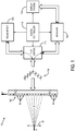
- a 3D FE model was constructed in Abaqus/CAE 6.10-EF1 (Dassault Systèmes Simulia Corp., Buffalo, RI, USA), as shown in Fig. 5 .
- the model was meshed with 2,000,000 8-node linear elements with reduced integration and hourglass control (C3D8R).
- the size of the each element is 0.5 ⁇ 0.5 ⁇ 0.5 mm 3 .
- tone burst excitations their frequencies were 100 to 500 Hz with 50 Hz separations and their peak-to-peak amplitudes were 20 ⁇ m. Each tone burst lasted 10 ms.
- the duration of the pulse was 100 ⁇ s and its amplitude was 20 ⁇ m.
- the medium of the model was assumed to be a Voigt material, which is described further below.
- the value of ⁇ 1 and ⁇ 2 are chosen because they are in the physical range of soft tissues.
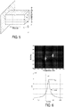
- Fig. 6 shows a representative k-space transform obtained by 2D FFT for a tone burst excitation at 100 Hz.
- the particle velocity values at each node were used in the computation.
- the magnitude profile at the excitation frequency is plotted in Fig. 6 .
- the peak location and pulse width were used to calculate wave speed and attenuation, respectively.
- Fig. 7 is a set of graphs that compare estimated shear wave speeds and attenuations for both tone burst and impulse excitations. The results show that, for both excitation types, the estimations matched the theoretical speeds and attenuations.
- the estimated attenuation by equation 18 comes only from material.
- geometric attenuation could be considered. Compensation for this geometric attenuation can be done by using the appropriate wave equations and applying a Fourier transform to their general solutions for each different wave type.
- the motion (or velocity, or acceleration) field has to be corrected by a factor of r or r , where r is the distance vector.
- a similar process can be performed for spherical waves with a factor of r instead of r used for the cylindrical waves.
- Performing a 2D Fourier transform on Eq. 24 results in the same expression as in Eq. 4, except that u 0 is multiplied by a constant, which does not change the shape of the peak in k-space so the velocity and attenuation measurements are invariant.
- a combination of the corrections for cylindrical and spherical waves, or a modification of either of them, can be used to account for propagations that are any mixture of plane, cylindrical and spherical waves.
- k-space analysis compared to some other methods for wave speed and attenuation estimation, such as phase and amplitude gradient methods, lies in its robustness to wave reflections.
- waves travelling in the positive direction have energy concentrated in the first and third quadrants of k-space. It can be shown that waves travelling in the opposite direction will have energy peaks only in the second and fourth quadrants. Therefore, k-space analysis can differentiate the waves in the desired direction from the reflected waves.
- a practical issue in performing a Fourier transform on sampled data is the length of the FFT. Normally, zero padding can be used to increase the resolution in the k-space domain. The present invention has verified that the proposed method is not affected by the number of points used in the Fourier transforms in both dimensions.
- Another issue related to Fourier transform is windowing. Applying a window modifies the energy distribution in time or spatial domain; it will affect the wave attenuation estimation, although wave speed estimation remains accurate.
- the present invention provides a system and method for ultrasound processes and analysis for estimating wave attenuation using k-space analysis.
- the present invention by using k-space analysis, provides improved robustness to wave reflections, since after Fourier transform, the reflected waves will appear in different quadrants from the waves of interest.
- Attenuation estimations in accordance with the present invention are not affected by zero padding in Fourier transform but will be biased if windowing is applied. Tests show that for tone burst and impulse excitations, the estimated wave speed and attenuation values match the expectations. While the foregoing descriptions were made with respect to plane wave, it can be extended to others, such as cylindrical and spherical waves, for example.
- any of the foregoing methods, processes, and steps may be embodied as systems or methods or computer-implemented processes.
- the foregoing may be performed by computer processors that are configured or have access to a computer-readable, non-transitory storage medium having instructions stored thereon. Whether direction configured or caused to when accessing the instructions, the computer processors may carry out the foregoing.
- the processor may be one of the above-described processors, for example, as described with respect to Figs. 1-3 .
Landscapes
- Engineering & Computer Science (AREA)
- Health & Medical Sciences (AREA)
- Physics & Mathematics (AREA)
- Life Sciences & Earth Sciences (AREA)
- Radar, Positioning & Navigation (AREA)
- Remote Sensing (AREA)
- General Physics & Mathematics (AREA)
- Computer Networks & Wireless Communication (AREA)
- Radiology & Medical Imaging (AREA)
- Biophysics (AREA)
- Medical Informatics (AREA)
- Molecular Biology (AREA)
- Surgery (AREA)
- Animal Behavior & Ethology (AREA)
- General Health & Medical Sciences (AREA)
- Public Health (AREA)
- Veterinary Medicine (AREA)
- Heart & Thoracic Surgery (AREA)
- Biomedical Technology (AREA)
- Pathology (AREA)
- Nuclear Medicine, Radiotherapy & Molecular Imaging (AREA)
- Acoustics & Sound (AREA)
- Physiology (AREA)
- Computer Vision & Pattern Recognition (AREA)
- Gynecology & Obstetrics (AREA)
- Ultra Sonic Daignosis Equipment (AREA)
- Investigating Or Analyzing Materials By The Use Of Ultrasonic Waves (AREA)
Claims (14)
- System (100) zum Bestimmen einer mechanischen Eigenschaft eines Gewebes einer Person, wobei das System (100) umfasst:einen Ultraschallsender (106), der eine Gruppe von Wandlern (102) ansteuert, so dass ein Ultraschallstrahl erzeugt wird, der im Wesentlichen rechtwinklig zur vorderen Oberfläche der Gruppe von Wandlern (102) ausgerichtet ist, so dass sich eine Scherwelle im Gewebe ausbreitet;einen Ultraschallempfänger (108), der dazu ausgelegt ist,- analoge Echosignale zu empfangen, die von der Gruppe von Wandlern (102) beim Ausbreiten der Scherwelle in der Person erzeugt werden als Antwort auf Ultraschallenergie, die vom Gewebe zurück zur Gruppe von Wandlern (102) reflektiert wird;- digitalisierte Strahlsamples aus den analogen Echosignalen zu erzeugen, wobei die digitalisierten Strahlsamples indikativ sind für eine Magnitude und eine Phase der analogen Echosignale;wobei der Empfänger (108) zudem einen Prozessor (160) umfasst,wobei der Prozessor (160) dazu ausgelegt ist,- die digitalisierten Strahlsamples zu empfangen, wobei die Ausbreitung der Scherwelle im Gewebe als Funktion von Zeit und Raum dargestellt wird; und- basierend auf den empfangenen Strahlsamples, eine mechanische Eigenschaft des Gewebes zu berechnen;wobei das Berechnen der mechanischen Eigenschaft umfasst:Durchführung einer zweidimensionalen (2D) Fouriertransformation der Scherwelle als Funktion von Zeit und Raum in die Zeitfrequenz- und Ortsfrequenzdomäne, um eine k-Raumdarstellung der Scherwelle zu erzeugen;Analysieren der k-Raumdarstellung der Scherwelle, um eine Dämpfung der Scherwelle beim Ausbreiten im Gewebe zu schätzen,wobei das Analysieren ein Identifizieren der Halbwertsbreite, FWHM, einer Spitze eines Magnitudenprofils der k-Raumdarstellung umfasst; undBerechnen der mechanischen Eigenschaft unter Nutzung der geschätzten Dämpfung der Scherwelle beim Ausbreiten im Gewebe.
- System (100) nach Anspruch 1, wobei das Berechnen der mechanischen Eigenschaft ein Analysieren der k-Raumdarstellung der Scherwelle umfasst, um eine Wellengeschwindigkeit der Scherwelle beim Ausbreiten im Gewebe zu schätzen, wobei das Analysieren ein Identifizieren einer Spitzenmagnitude des Magnitudenprofils der k-Raumdarstellung umfasst.
- System (100) nach Anspruch 2, wobei die mechanische Eigenschaft das komplexe Schermodul, G*, des Gewebes ist.
- System (100) nach Anspruch 1, wobei das Analysieren zudem ein Bestimmen einer Frequenz, f0, der Scherwelle umfasst, so dass das Magnitudenprofil eine Spitze bei (k, f) = (fo/c,fo) aufweist, wobei k die Ortsfrequenz- oder Wellenzahlvariable ist und f die Zeitfrequenzvariable ist, die mit der Scherwelle assoziiert werden, und c die Wellengeschwindigkeit der Scherwelle ist.
- System (100) nach Anspruch 1, wobei das Analysieren ein Berechnen der Dämpfung der Scherwelle als

wobei α die Dämpfung der Scherwelle und FWHM eine Halbwertsbreite, FWHM, ist. - System (100) nach Anspruch 1, wobei bei dem Berechnen der mechanischen Eigenschaft die Scherwelle als eindimensionale, ebene Scherwelle, behandelt wird, die sich in einem linearen viskoelastischen Medium ausbreitet.
- System (100) nach Anspruch 6, wobei die eindimensionale, ebene Scherwelle, die sich in einem linearen viskoelastischen Medium ausbreitet, beschrieben wird durch:

- System (100) nach Anspruch 1, wobei die durch die Scherwelle verursachte Verschiebung des Gewebes beschrieben wird durch:

- System (100) nach Anspruch 1, wobei das Durchführen einer zweidimensionalen (2D) Fouriertransformation ein Transformieren von u(x, t) in den k-Raum umfasst, um

wobei k und f die Wellenzahl- beziehungsweise Zeitfrequenzvariable sind, die beide reell sind. - Verfahren zum Bestimmen einer mechanischen Eigenschaft eines Gewebes einer Person, wobei das Verfahren umfasst:Erzeugung eines Ultraschallstrahls mittels einer Gruppe von Wandlern (102), der im Wesentlichen rechtwinklig zur vorderen Oberfläche der Gruppe von Wandlern ausgerichtet ist, so dass sich eine Scherwelle im Gewebe ausbreitet;Empfangen von analogen Echosignalen beim Ausbreiten der Scherwelle in der Person als Antwort auf Ultraschallenergie, die vom Gewebe zurückreflektiert wird;Erzeugung digitalisierter Strahlsamples aus den empfangenen analogen Echosignalen, wobei die digitalisierten Strahlsamples indikativ sind für eine Magnitude und eine Phase der analogen Echosignale;Empfangen der digitalisierten Strahlsamples, wobei die Ausbreitung der Scherwelle im Gewebe als Funktion von Zeit und Raum dargestellt wird; undbasierend auf den empfangenen Strahlsamples, Berechnen einer mechanischen Eigenschaft des Gewebes;wobei das Berechnen der mechanischen Eigenschaft umfasst:Durchführung einer zweidimensionalen, 2D, Fouriertransformation der Scherwelle als Funktion von Zeit und Raum in die Zeitfrequenz- und Ortsfrequenzdomäne, um eine k-Raumdarstellung der Scherwelle zu erzeugen.Analysieren der k-Raumdarstellung der Scherwelle, um eine Dämpfung der Scherwelle bei der Ausbreitung im Gewebe zu schätzen,
wobei das Analysieren ein Identifizieren der Halbwertsbreite, FWHM, einer Spitze eines Magnitudenprofils der k-Raumdarstellung umfasst; undBerechnen der mechanischen Eigenschaft unter Nutzung der geschätzten Dämpfung der Scherwelle beim Ausbreiten im Gewebe. - Verfahren nach Anspruch 10, wobei das Berechnen der mechanischen Eigenschaft ein Analysieren der k-Raumdarstellung der Scherwelle umfasst, um eine Wellengeschwindigkeit der Scherwelle beim Ausbreiten im Gewebe zu schätzen, wobei das Analysieren ein Identifizieren einer Spitzenmagnitude des Magnitudenprofils der k-Raumdarstellung umfasst.
- Verfahren nach Anspruch 11, wobei die mechanische Eigenschaft das komplexe Schermodul, G*, des Gewebes ist.
- Verfahren nach Anspruch 10, wobei das Analysieren zudem ein Bestimmen einer Frequenz, f0, der Scherwelle umfasst, so dass das Magnitudenprofil eine Spitze bei (k,f) = (f0 /c,f0) aufweist, wobei k die Ortsfrequenz- oder Wellenzahlvariable und f die Zeitfrequenzvariable ist, die mit der Scherwelle assoziiert werden, und c die Wellengeschwindigkeit der Scherwelle ist.
- Verfahren nach Anspruch 10 wobei das Analysieren ein Berechnen der Dämpfung der Scherwelle als

wobei α die Dämpfung der Scherwelle und FWHM eine Halbwertsbreite, FWHM, ist.
Applications Claiming Priority (2)
| Application Number | Priority Date | Filing Date | Title |
|---|---|---|---|
| US201261708382P | 2012-10-01 | 2012-10-01 | |
| PCT/US2013/062617 WO2014055410A1 (en) | 2012-10-01 | 2013-09-30 | Shear wave attenuation from k-space analysis system |
Publications (3)
| Publication Number | Publication Date |
|---|---|
| EP2903530A1 EP2903530A1 (de) | 2015-08-12 |
| EP2903530A4 EP2903530A4 (de) | 2016-06-15 |
| EP2903530B1 true EP2903530B1 (de) | 2019-08-07 |
Family
ID=50435345
Family Applications (1)
| Application Number | Title | Priority Date | Filing Date |
|---|---|---|---|
| EP13844129.0A Active EP2903530B1 (de) | 2012-10-01 | 2013-09-30 | Scherwellenabschwächung aus k-raum-analysesystem |
Country Status (3)
| Country | Link |
|---|---|
| US (1) | US9642600B2 (de) |
| EP (1) | EP2903530B1 (de) |
| WO (1) | WO2014055410A1 (de) |
Families Citing this family (7)
| Publication number | Priority date | Publication date | Assignee | Title |
|---|---|---|---|---|
| US9918698B2 (en) * | 2012-10-01 | 2018-03-20 | Mayo Foundation For Medical Education And Research | System and method for gradient-based k-space search for shear wave velocity dispersion estimation |
| US10376242B2 (en) | 2015-04-16 | 2019-08-13 | Siemens Medical Solutions Usa, Inc. | Quantitative viscoelastic ultrasound imaging |
| US10729404B2 (en) | 2015-08-03 | 2020-08-04 | Koninklijke Philips N.V. | Ultrasound system and method for measurement using shear wave |
| US10376233B2 (en) | 2016-04-08 | 2019-08-13 | Siemens Medical Solutions Usa, Inc. | Diffraction source compensation in medical diagnostic ultrasound viscoelastic imaging |
| CN107505232B (zh) | 2017-07-21 | 2019-09-03 | 无锡海斯凯尔医学技术有限公司 | 运动信息获取方法及装置 |
| US11426146B2 (en) | 2017-09-08 | 2022-08-30 | Samsung Medison Co., Ltd. | Ultrasound imaging apparatus and control method thereof |
| US11154277B2 (en) * | 2017-10-31 | 2021-10-26 | Siemens Medical Solutions Usa, Inc. | Tissue viscoelastic estimation from shear velocity in ultrasound medical imaging |
Family Cites Families (4)
| Publication number | Priority date | Publication date | Assignee | Title |
|---|---|---|---|---|
| US6246895B1 (en) * | 1998-12-18 | 2001-06-12 | Sunnybrook Health Science Centre | Imaging of ultrasonic fields with MRI |
| US7166075B2 (en) * | 2002-03-08 | 2007-01-23 | Wisconsin Alumni Research Foundation | Elastographic imaging of in vivo soft tissue |
| KR101139123B1 (ko) | 2008-07-10 | 2012-04-30 | 삼성메디슨 주식회사 | 영상 깊이를 조절하는 초음파 장치 및 방법 |
| US8469891B2 (en) | 2011-02-17 | 2013-06-25 | Siemens Medical Solutions Usa, Inc. | Viscoelasticity measurement using amplitude-phase modulated ultrasound wave |
-
2013
- 2013-09-30 EP EP13844129.0A patent/EP2903530B1/de active Active
- 2013-09-30 US US14/432,312 patent/US9642600B2/en active Active
- 2013-09-30 WO PCT/US2013/062617 patent/WO2014055410A1/en not_active Ceased
Non-Patent Citations (1)
| Title |
|---|
| None * |
Also Published As
| Publication number | Publication date |
|---|---|
| US20150305719A1 (en) | 2015-10-29 |
| WO2014055410A1 (en) | 2014-04-10 |
| EP2903530A1 (de) | 2015-08-12 |
| EP2903530A4 (de) | 2016-06-15 |
| US9642600B2 (en) | 2017-05-09 |
Similar Documents
| Publication | Publication Date | Title |
|---|---|---|
| EP2903530B1 (de) | Scherwellenabschwächung aus k-raum-analysesystem | |
| KR101868381B1 (ko) | 의료용 초음파 이미징에서의 전단파 정보의 해석 | |
| US10159466B2 (en) | Sparse tracking in acoustic radiation force impulse imaging | |
| KR101398948B1 (ko) | 진폭―위상 변조된 초음파를 이용한 점탄성 측정 | |
| EP0123427B1 (de) | Charakterisierung eines Mediums mit Hilfe von Ultraschall | |
| CN114391868B (zh) | 量化的粘弹性超声成像 | |
| US8734350B2 (en) | System and method for correcting errors in shear wave measurements arising from ultrasound beam geometry | |
| CN106419961B (zh) | 声学辐射力成像中的自适应运动估计 | |
| US10324063B2 (en) | Methods and systems for measuring properties with ultrasound | |
| Bigelow et al. | Attenuation compensation and estimation | |
| US10327739B2 (en) | Measuring tissue shear wave properties using one excitation pulse and excitation pulses having different widths and shapes | |
| CN114176625A (zh) | 用于介质的超声表征的方法和系统 | |
| US20130237821A1 (en) | System and Method for Model-Independent Quantification of Tissue Viscoelastic Properties Using Ultrasound | |
| Malo et al. | Wave mode discrimination of coded ultrasonic guided waves using two-dimensional compressed pulse analysis | |
| US11717256B2 (en) | Motion independence in acoustic radiation force impulse imaging | |
| Shaswary et al. | Performance study of a new time-delay estimation algorithm in ultrasonic echo signals and ultrasound elastography | |
| JP4297699B2 (ja) | スペクトル歪み度を描出するための方法及び装置 | |
| CN116419717A (zh) | 用于介质的超声表征的方法和系统 | |
| CN110840488B (zh) | 一种基于剪切波的成像方法、系统及装置 | |
| US9918698B2 (en) | System and method for gradient-based k-space search for shear wave velocity dispersion estimation | |
| CN112799078B (zh) | 一种剪切波传播速度的检测方法、系统和超声成像设备 | |
| JP2669204B2 (ja) | 探査装置 | |
| McAleavey | Single tracking location shear wave elastography | |
| JP2014030774A (ja) | 関心領域の粘弾性の平均値を測定するための方法および装置 | |
| JPH0239253B2 (de) |
Legal Events
| Date | Code | Title | Description |
|---|---|---|---|
| PUAI | Public reference made under article 153(3) epc to a published international application that has entered the european phase |
Free format text: ORIGINAL CODE: 0009012 |
|
| 17P | Request for examination filed |
Effective date: 20150429 |
|
| AK | Designated contracting states |
Kind code of ref document: A1 Designated state(s): AL AT BE BG CH CY CZ DE DK EE ES FI FR GB GR HR HU IE IS IT LI LT LU LV MC MK MT NL NO PL PT RO RS SE SI SK SM TR |
|
| AX | Request for extension of the european patent |
Extension state: BA ME |
|
| DAX | Request for extension of the european patent (deleted) | ||
| REG | Reference to a national code |
Ref country code: DE Ref legal event code: R079 Ref document number: 602013058940 Country of ref document: DE Free format text: PREVIOUS MAIN CLASS: A61B0008000000 Ipc: G01S0007520000 |
|
| RA4 | Supplementary search report drawn up and despatched (corrected) |
Effective date: 20160517 |
|
| RIC1 | Information provided on ipc code assigned before grant |
Ipc: G01S 15/89 20060101ALI20160510BHEP Ipc: A61B 8/08 20060101ALI20160510BHEP Ipc: G01S 7/52 20060101AFI20160510BHEP |
|
| STAA | Information on the status of an ep patent application or granted ep patent |
Free format text: STATUS: EXAMINATION IS IN PROGRESS |
|
| 17Q | First examination report despatched |
Effective date: 20180322 |
|
| GRAP | Despatch of communication of intention to grant a patent |
Free format text: ORIGINAL CODE: EPIDOSNIGR1 |
|
| STAA | Information on the status of an ep patent application or granted ep patent |
Free format text: STATUS: GRANT OF PATENT IS INTENDED |
|
| INTG | Intention to grant announced |
Effective date: 20190220 |
|
| GRAS | Grant fee paid |
Free format text: ORIGINAL CODE: EPIDOSNIGR3 |
|
| GRAA | (expected) grant |
Free format text: ORIGINAL CODE: 0009210 |
|
| STAA | Information on the status of an ep patent application or granted ep patent |
Free format text: STATUS: THE PATENT HAS BEEN GRANTED |
|
| AK | Designated contracting states |
Kind code of ref document: B1 Designated state(s): AL AT BE BG CH CY CZ DE DK EE ES FI FR GB GR HR HU IE IS IT LI LT LU LV MC MK MT NL NO PL PT RO RS SE SI SK SM TR |
|
| REG | Reference to a national code |
Ref country code: GB Ref legal event code: FG4D |
|
| REG | Reference to a national code |
Ref country code: CH Ref legal event code: EP Ref country code: AT Ref legal event code: REF Ref document number: 1164699 Country of ref document: AT Kind code of ref document: T Effective date: 20190815 |
|
| REG | Reference to a national code |
Ref country code: DE Ref legal event code: R096 Ref document number: 602013058940 Country of ref document: DE |
|
| REG | Reference to a national code |
Ref country code: IE Ref legal event code: FG4D |
|
| REG | Reference to a national code |
Ref country code: NL Ref legal event code: FP |
|
| REG | Reference to a national code |
Ref country code: LT Ref legal event code: MG4D |
|
| PG25 | Lapsed in a contracting state [announced via postgrant information from national office to epo] |
Ref country code: NO Free format text: LAPSE BECAUSE OF FAILURE TO SUBMIT A TRANSLATION OF THE DESCRIPTION OR TO PAY THE FEE WITHIN THE PRESCRIBED TIME-LIMIT Effective date: 20191107 Ref country code: BG Free format text: LAPSE BECAUSE OF FAILURE TO SUBMIT A TRANSLATION OF THE DESCRIPTION OR TO PAY THE FEE WITHIN THE PRESCRIBED TIME-LIMIT Effective date: 20191107 Ref country code: HR Free format text: LAPSE BECAUSE OF FAILURE TO SUBMIT A TRANSLATION OF THE DESCRIPTION OR TO PAY THE FEE WITHIN THE PRESCRIBED TIME-LIMIT Effective date: 20190807 Ref country code: LT Free format text: LAPSE BECAUSE OF FAILURE TO SUBMIT A TRANSLATION OF THE DESCRIPTION OR TO PAY THE FEE WITHIN THE PRESCRIBED TIME-LIMIT Effective date: 20190807 Ref country code: FI Free format text: LAPSE BECAUSE OF FAILURE TO SUBMIT A TRANSLATION OF THE DESCRIPTION OR TO PAY THE FEE WITHIN THE PRESCRIBED TIME-LIMIT Effective date: 20190807 Ref country code: PT Free format text: LAPSE BECAUSE OF FAILURE TO SUBMIT A TRANSLATION OF THE DESCRIPTION OR TO PAY THE FEE WITHIN THE PRESCRIBED TIME-LIMIT Effective date: 20191209 Ref country code: SE Free format text: LAPSE BECAUSE OF FAILURE TO SUBMIT A TRANSLATION OF THE DESCRIPTION OR TO PAY THE FEE WITHIN THE PRESCRIBED TIME-LIMIT Effective date: 20190807 |
|
| REG | Reference to a national code |
Ref country code: AT Ref legal event code: MK05 Ref document number: 1164699 Country of ref document: AT Kind code of ref document: T Effective date: 20190807 |
|
| PG25 | Lapsed in a contracting state [announced via postgrant information from national office to epo] |
Ref country code: AL Free format text: LAPSE BECAUSE OF FAILURE TO SUBMIT A TRANSLATION OF THE DESCRIPTION OR TO PAY THE FEE WITHIN THE PRESCRIBED TIME-LIMIT Effective date: 20190807 Ref country code: GR Free format text: LAPSE BECAUSE OF FAILURE TO SUBMIT A TRANSLATION OF THE DESCRIPTION OR TO PAY THE FEE WITHIN THE PRESCRIBED TIME-LIMIT Effective date: 20191108 Ref country code: IS Free format text: LAPSE BECAUSE OF FAILURE TO SUBMIT A TRANSLATION OF THE DESCRIPTION OR TO PAY THE FEE WITHIN THE PRESCRIBED TIME-LIMIT Effective date: 20191207 Ref country code: RS Free format text: LAPSE BECAUSE OF FAILURE TO SUBMIT A TRANSLATION OF THE DESCRIPTION OR TO PAY THE FEE WITHIN THE PRESCRIBED TIME-LIMIT Effective date: 20190807 Ref country code: LV Free format text: LAPSE BECAUSE OF FAILURE TO SUBMIT A TRANSLATION OF THE DESCRIPTION OR TO PAY THE FEE WITHIN THE PRESCRIBED TIME-LIMIT Effective date: 20190807 Ref country code: ES Free format text: LAPSE BECAUSE OF FAILURE TO SUBMIT A TRANSLATION OF THE DESCRIPTION OR TO PAY THE FEE WITHIN THE PRESCRIBED TIME-LIMIT Effective date: 20190807 |
|
| PG25 | Lapsed in a contracting state [announced via postgrant information from national office to epo] |
Ref country code: TR Free format text: LAPSE BECAUSE OF FAILURE TO SUBMIT A TRANSLATION OF THE DESCRIPTION OR TO PAY THE FEE WITHIN THE PRESCRIBED TIME-LIMIT Effective date: 20190807 |
|
| PG25 | Lapsed in a contracting state [announced via postgrant information from national office to epo] |
Ref country code: RO Free format text: LAPSE BECAUSE OF FAILURE TO SUBMIT A TRANSLATION OF THE DESCRIPTION OR TO PAY THE FEE WITHIN THE PRESCRIBED TIME-LIMIT Effective date: 20190807 Ref country code: DK Free format text: LAPSE BECAUSE OF FAILURE TO SUBMIT A TRANSLATION OF THE DESCRIPTION OR TO PAY THE FEE WITHIN THE PRESCRIBED TIME-LIMIT Effective date: 20190807 Ref country code: AT Free format text: LAPSE BECAUSE OF FAILURE TO SUBMIT A TRANSLATION OF THE DESCRIPTION OR TO PAY THE FEE WITHIN THE PRESCRIBED TIME-LIMIT Effective date: 20190807 Ref country code: EE Free format text: LAPSE BECAUSE OF FAILURE TO SUBMIT A TRANSLATION OF THE DESCRIPTION OR TO PAY THE FEE WITHIN THE PRESCRIBED TIME-LIMIT Effective date: 20190807 Ref country code: PL Free format text: LAPSE BECAUSE OF FAILURE TO SUBMIT A TRANSLATION OF THE DESCRIPTION OR TO PAY THE FEE WITHIN THE PRESCRIBED TIME-LIMIT Effective date: 20190807 |
|
| PG25 | Lapsed in a contracting state [announced via postgrant information from national office to epo] |
Ref country code: CZ Free format text: LAPSE BECAUSE OF FAILURE TO SUBMIT A TRANSLATION OF THE DESCRIPTION OR TO PAY THE FEE WITHIN THE PRESCRIBED TIME-LIMIT Effective date: 20190807 Ref country code: SK Free format text: LAPSE BECAUSE OF FAILURE TO SUBMIT A TRANSLATION OF THE DESCRIPTION OR TO PAY THE FEE WITHIN THE PRESCRIBED TIME-LIMIT Effective date: 20190807 Ref country code: MC Free format text: LAPSE BECAUSE OF FAILURE TO SUBMIT A TRANSLATION OF THE DESCRIPTION OR TO PAY THE FEE WITHIN THE PRESCRIBED TIME-LIMIT Effective date: 20190807 Ref country code: IS Free format text: LAPSE BECAUSE OF FAILURE TO SUBMIT A TRANSLATION OF THE DESCRIPTION OR TO PAY THE FEE WITHIN THE PRESCRIBED TIME-LIMIT Effective date: 20200224 Ref country code: SM Free format text: LAPSE BECAUSE OF FAILURE TO SUBMIT A TRANSLATION OF THE DESCRIPTION OR TO PAY THE FEE WITHIN THE PRESCRIBED TIME-LIMIT Effective date: 20190807 |
|
| REG | Reference to a national code |
Ref country code: CH Ref legal event code: PL |
|
| REG | Reference to a national code |
Ref country code: DE Ref legal event code: R097 Ref document number: 602013058940 Country of ref document: DE |
|
| PLBE | No opposition filed within time limit |
Free format text: ORIGINAL CODE: 0009261 |
|
| STAA | Information on the status of an ep patent application or granted ep patent |
Free format text: STATUS: NO OPPOSITION FILED WITHIN TIME LIMIT |
|
| PG2D | Information on lapse in contracting state deleted |
Ref country code: IS |
|
| PG25 | Lapsed in a contracting state [announced via postgrant information from national office to epo] |
Ref country code: LU Free format text: LAPSE BECAUSE OF NON-PAYMENT OF DUE FEES Effective date: 20190930 Ref country code: IE Free format text: LAPSE BECAUSE OF NON-PAYMENT OF DUE FEES Effective date: 20190930 Ref country code: CH Free format text: LAPSE BECAUSE OF NON-PAYMENT OF DUE FEES Effective date: 20190930 Ref country code: LI Free format text: LAPSE BECAUSE OF NON-PAYMENT OF DUE FEES Effective date: 20190930 |
|
| REG | Reference to a national code |
Ref country code: BE Ref legal event code: MM Effective date: 20190930 |
|
| 26N | No opposition filed |
Effective date: 20200603 |
|
| PG25 | Lapsed in a contracting state [announced via postgrant information from national office to epo] |
Ref country code: BE Free format text: LAPSE BECAUSE OF NON-PAYMENT OF DUE FEES Effective date: 20190930 Ref country code: SI Free format text: LAPSE BECAUSE OF FAILURE TO SUBMIT A TRANSLATION OF THE DESCRIPTION OR TO PAY THE FEE WITHIN THE PRESCRIBED TIME-LIMIT Effective date: 20190807 |
|
| PG25 | Lapsed in a contracting state [announced via postgrant information from national office to epo] |
Ref country code: CY Free format text: LAPSE BECAUSE OF FAILURE TO SUBMIT A TRANSLATION OF THE DESCRIPTION OR TO PAY THE FEE WITHIN THE PRESCRIBED TIME-LIMIT Effective date: 20190807 |
|
| PG25 | Lapsed in a contracting state [announced via postgrant information from national office to epo] |
Ref country code: HU Free format text: LAPSE BECAUSE OF FAILURE TO SUBMIT A TRANSLATION OF THE DESCRIPTION OR TO PAY THE FEE WITHIN THE PRESCRIBED TIME-LIMIT; INVALID AB INITIO Effective date: 20130930 Ref country code: MT Free format text: LAPSE BECAUSE OF FAILURE TO SUBMIT A TRANSLATION OF THE DESCRIPTION OR TO PAY THE FEE WITHIN THE PRESCRIBED TIME-LIMIT Effective date: 20190807 |
|
| PG25 | Lapsed in a contracting state [announced via postgrant information from national office to epo] |
Ref country code: MK Free format text: LAPSE BECAUSE OF FAILURE TO SUBMIT A TRANSLATION OF THE DESCRIPTION OR TO PAY THE FEE WITHIN THE PRESCRIBED TIME-LIMIT Effective date: 20190807 |
|
| P01 | Opt-out of the competence of the unified patent court (upc) registered |
Effective date: 20230528 |
|
| PGFP | Annual fee paid to national office [announced via postgrant information from national office to epo] |
Ref country code: DE Payment date: 20250929 Year of fee payment: 13 |
|
| PGFP | Annual fee paid to national office [announced via postgrant information from national office to epo] |
Ref country code: IT Payment date: 20250919 Year of fee payment: 13 Ref country code: NL Payment date: 20250926 Year of fee payment: 13 |
|
| PGFP | Annual fee paid to national office [announced via postgrant information from national office to epo] |
Ref country code: GB Payment date: 20250929 Year of fee payment: 13 |
|
| PGFP | Annual fee paid to national office [announced via postgrant information from national office to epo] |
Ref country code: FR Payment date: 20250925 Year of fee payment: 13 |