EP2903529B1 - Tool for opening and closing a transducer housing - Google Patents
Tool for opening and closing a transducer housing Download PDFInfo
- Publication number
- EP2903529B1 EP2903529B1 EP13808219.3A EP13808219A EP2903529B1 EP 2903529 B1 EP2903529 B1 EP 2903529B1 EP 13808219 A EP13808219 A EP 13808219A EP 2903529 B1 EP2903529 B1 EP 2903529B1
- Authority
- EP
- European Patent Office
- Prior art keywords
- tool
- base portion
- upper portion
- transducer housing
- lid
- Prior art date
- Legal status (The legal status is an assumption and is not a legal conclusion. Google has not performed a legal analysis and makes no representation as to the accuracy of the status listed.)
- Active
Links
- 230000008878 coupling Effects 0.000 claims description 24
- 238000010168 coupling process Methods 0.000 claims description 24
- 238000005859 coupling reaction Methods 0.000 claims description 24
- 238000003780 insertion Methods 0.000 claims description 13
- 230000037431 insertion Effects 0.000 claims description 13
- 230000001605 fetal effect Effects 0.000 description 8
- 238000012544 monitoring process Methods 0.000 description 5
- 210000001331 nose Anatomy 0.000 description 5
- 210000000887 face Anatomy 0.000 description 4
- 230000002093 peripheral effect Effects 0.000 description 4
- 230000008439 repair process Effects 0.000 description 4
- 230000001419 dependent effect Effects 0.000 description 3
- 238000013461 design Methods 0.000 description 3
- 210000003754 fetus Anatomy 0.000 description 3
- 208000036029 Uterine contractions during pregnancy Diseases 0.000 description 2
- 208000027418 Wounds and injury Diseases 0.000 description 2
- 230000008901 benefit Effects 0.000 description 2
- 230000006378 damage Effects 0.000 description 2
- 239000003292 glue Substances 0.000 description 2
- 208000014674 injury Diseases 0.000 description 2
- 239000002184 metal Substances 0.000 description 2
- 238000000034 method Methods 0.000 description 2
- 238000012806 monitoring device Methods 0.000 description 2
- 238000002606 obstetric ultrasonography Methods 0.000 description 2
- 230000000007 visual effect Effects 0.000 description 2
- 0 C1*2CCC1C2 Chemical compound C1*2CCC1C2 0.000 description 1
- 239000008280 blood Substances 0.000 description 1
- 210000004369 blood Anatomy 0.000 description 1
- 230000001066 destructive effect Effects 0.000 description 1
- 230000003670 easy-to-clean Effects 0.000 description 1
- 230000000694 effects Effects 0.000 description 1
- 210000002458 fetal heart Anatomy 0.000 description 1
- 230000036541 health Effects 0.000 description 1
- 230000003993 interaction Effects 0.000 description 1
- 210000001161 mammalian embryo Anatomy 0.000 description 1
- 238000005259 measurement Methods 0.000 description 1
- 230000007246 mechanism Effects 0.000 description 1
- 210000003097 mucus Anatomy 0.000 description 1
- 230000035935 pregnancy Effects 0.000 description 1
- 230000002265 prevention Effects 0.000 description 1
- 238000011160 research Methods 0.000 description 1
- 210000004291 uterus Anatomy 0.000 description 1
Images


Classifications
-
- A—HUMAN NECESSITIES
- A61—MEDICAL OR VETERINARY SCIENCE; HYGIENE
- A61B—DIAGNOSIS; SURGERY; IDENTIFICATION
- A61B8/00—Diagnosis using ultrasonic, sonic or infrasonic waves
- A61B8/08—Detecting organic movements or changes, e.g. tumours, cysts, swellings
- A61B8/0866—Detecting organic movements or changes, e.g. tumours, cysts, swellings involving foetal diagnosis; pre-natal or peri-natal diagnosis of the baby
-
- A—HUMAN NECESSITIES
- A61—MEDICAL OR VETERINARY SCIENCE; HYGIENE
- A61B—DIAGNOSIS; SURGERY; IDENTIFICATION
- A61B8/00—Diagnosis using ultrasonic, sonic or infrasonic waves
- A61B8/44—Constructional features of the ultrasonic, sonic or infrasonic diagnostic device
- A61B8/4411—Device being modular
-
- A—HUMAN NECESSITIES
- A61—MEDICAL OR VETERINARY SCIENCE; HYGIENE
- A61B—DIAGNOSIS; SURGERY; IDENTIFICATION
- A61B8/00—Diagnosis using ultrasonic, sonic or infrasonic waves
- A61B8/44—Constructional features of the ultrasonic, sonic or infrasonic diagnostic device
- A61B8/4444—Constructional features of the ultrasonic, sonic or infrasonic diagnostic device related to the probe
- A61B8/4455—Features of the external shape of the probe, e.g. ergonomic aspects
Definitions
- the present invention relates to a tool for opening and closing a transducer housing, in particular a housing of a fetal monitoring transducer. Further, the present invention relates to a kit comprising such a tool and such a transducer housing.
- cardiotocographs more commonly known as electronic fetal monitors (EFM).
- ultrasonic transducers or other ultrasonic-based sensors are used. These ultrasonic transducers and other electronic periphery devices need to be encapsulated in a liquid-tight housing. Usually two half-shells are used to provide an encapsulated volume for the measurement transducers and the peripheral devices of the fetal monitoring apparatus.
- the transducer housings After usage the transducer housings have to be cleaned and disinfected. On the other hand, the transducer housing needs to be absolutely liquid-tight, as the housing is usually contaminated with a lot of blood and mucus if used during birth. In most cases the two half-shells of the transducer housing are therefore either glued together or joined with each other using screws.
- a connection of the two half-shells of the transducer housing via screws is also not advantageous.
- screws have a negative visual impact on the transducer housing and could negatively influence the design of the transducer housing.
- the metal parts of the screws could have a negative influence to a radio system of a wireless transducer.
- the screws occupy space within the transducer housing. Apart from that gaps and sharp edges might occur when using screws as connection parts, which could lead to unwanted injuries of the patient.
- Another negative effect is that a physician him-/herself could try to open the transducer housing in order to repair or clean the ultrasonic transducer or peripheral devices connected thereto. However, such a self-repair shall be prevented in any case.
- US 3,930,427 A discloses a tool for tightening and untightening screw-type bottoms or backs of watch casings in which the spindle by which the bottom is rotated is threaded to a tool stand using the same pitch of thread as that of the threads on the watchcase bottom, so that as the spindle is rotated it is displaced axially by the same amount as the bottom, thereby keeping the tool on the spindle in proper engagement with the bottom of the case.
- US 3,625,093 A discloses a similar tool for tightening and untightening the bottom of a watch-casing.
- a tool for opening and closing a transducer housing having two housing parts, a base body and a lid, is provided, the two housing parts being coupleable with each other via a rotational coupling, wherein the tool comprises:
- kit that comprises:
- transducer housing that comprises:
- One of the central points of the present invention is the provision of a transducer housing with two housing parts, that are herein denoted as the base body and the lid, which may be coupled with each other via a rotational coupling.
- the rotational coupling is preferably integrated into the transducer housing.
- a rotational coupling shall be any coupling that allows coupling the lid and the base body with each other upon a rotation of the two parts relative to each other.
- Well-known examples are a threaded coupling or a bayonet mount. However, also other rotational couplings may be used without leaving the scope of the present invention.
- the rotational coupling is realized as a bayonet mount.
- the integrated bayonet mount provides locking and release of the two half-shells (two housing parts) of the transducer housing.
- the transducer housing is designed such that it may be only opened and/or closed using the herein presented opening and closing tool. An unintentional opening or an opening of the transducer housing by an unauthorized person is therefore permitted. Only persons, who are in possession of the herein presented special tool, are able to open the transducer housing. In a hospital, for example, only people working in a service and repair ward may have the herein presented special opening and closing tool, so that only these people are enabled to open and close the transducer housing for service and repair reasons (but not the physician him-/herself).
- a further advantage of the herein presented transducer housing is an easy cleanability, since it preferable does not have any sharp edges. Most parts of the outer surface of the transducer housing are rounded or concave surfaces. Therefore, a risk of injury is minimized. Since there are no sharp edges, it is very difficult or almost impossible to open the transducer housing without the herein presented tool. An opening simply by hand is not possible, since there are no edges that can be caught in order to exert a sufficiently large torque on the lid of the housing for opening the bayonet mount.
- transducer housing shall denote any type of housing that is suitable for encasing a transducer. It is not restricted to any specific type, shape or size. It does not have to include the transducer itself.
- the lid of the transducer housing comprises a contact area that may be contacted by the above-mentioned driving pin of the tool.
- a form fit between the tool and the transducer housing is preferably established that allows to open and/or close the lid of the transducer housing. Since the transducer housing makes use of a bayonet mechanism that is integrated into the two housing parts (the base body and the lid), there is no visual impact to the transducer shell. Since no screws have to be used, the bayonet mount also eliminates the negative influence of the metal parts that could disturb the radio system of a wireless transducer. The absence of gaps and interrupted surfaces also makes it easy to clean the transducer device.
- the tool preferably comprises two separate parts, a base portion and an upper portion.
- the base portion forms a kind of bowl for receiving the transducer housing. If the transducer housing is inserted into said base portion of the tool, a rotation of the base body of the transducer housing relative to the base portion of the tool around the axial direction of the tool is prevented.
- This rotation prevention may be realized in many ways. In the simplest case a form fit between an inner wall of the base portion of the tool and at least a part of an outer wall of the base body of the transducer housing is realized.
- the outer wall of the transducer housing may, for example, have the same or corresponding shape as the inner wall of the base portion of the tool in order to create a form fit at the interface between the transducer housing and the tool.
- the two parts of the tool are preferably realized as two separate parts that are coupleable with each other.
- the upper portion of the tool serves as a kind of lid that may be attached to the base portion of the tool. Parts of the upper portion may interlock with parts of the base portion to prevent a relative movement in radial direction (perpendicular to the axial direction).
- the base portion comprises an inner wall and the upper portion comprises an outer wall that faces the inner wall of the base portion when the upper portion and the base portion are coupled with each other.
- At least a part of said inner wall of the base portion of the tool may form a form fit with at least a part of the outer wall of the upper portion of the tool. This form fit may prevent a movement of the upper portion relative to the base portion in the radial direction.
- the engagement between the two parts of the tool may be realized by two or more engagement members: a first engagement member which is arranged on the base portion of the tool and a second engagement member which is arranged on the upper portion of the tool and engages the first engagement member, when the upper portion and the base portion of the tool are coupled with each other.
- This engagement between the at least two engagement members serves as a mechanical guidance that allows a rotational movement of the upper portion relative to the base portion around the axial direction.
- a user may thus attach the upper portion to the base portion of the tool and rotate the upper portion by hand around the axial direction relative to the base portion. The user, for example, holds the base portion in one hand while turning the upper portion of the tool relative thereto with the other hand, either clockwise or counter-clockwise, around the axial direction.
- a further important part of the tool is the driving pin that is arranged on the upper portion of the tool.
- this driving pin When rotating the upper portion of the tool around the axial direction, this driving pin is rotated as well. It comprises a driving area for contacting a corresponding contact area of the lid of the transducer housing.
- the driving pin exerts a force on the lid of the transducer housing when the upper portion of the tool is rotated around the axial direction relative to the base portion of the tool.
- This force causes the lid of the transducer housing to rotate synchronically with the upper portion of the tool as soon as a user rotates the upper portion relative to the base portion.
- the upper portion of the tool therefore acts as a kind of mechanical lever that enables to push the lid of the transducer housing.
- the driving pin contacts the lid of the transducer housing and causes it to move relative to the base body of the transducer housing in order to open or close the bayonet mount. Since a form fit between the base portion of the tool and the base body of the transducer housing prevents a rotation of the base body of the transducer housing within the tool, only the lid of the transducer housing is forced into rotation (together with the upper portion of the tool). The base body of the transducer housing thereby remains still. A clockwise rotation of the upper portion of the tool could, for example, cause the bayonet mount to open, while a counter-clockwise of the upper portion of the tool could cause the bayonet mount to close.
- the movement of the base body of the transducer housing relative to the base portion of the tool around the axial direction is prevented as follows:
- the inner wall of the base portion may have a cylindrically curved surface area, wherein parts of said inner wall deviate from the cylindrical shape and comprise a planar contact surface for contacting a corresponding contact surface of the transducer housing.
- the interaction between these two contact surfaces of the tool and the base body of the transducer housing then prevents a rotation of the base body of the transducer housing relative to the base portion of the tool around the axial direction.
- the planar contact surface of the inner wall of the base portion of the tool may thereto be arranged perpendicular to the circumferential direction of the tool.
- the circumferential direction in this case denotes the direction that is perpendicular to the axial direction as well as perpendicular to the radial direction of the tool.
- the outer wall of the base body of the transducer housing as well as the inner wall of the base portion of the tool could, for example, both have a corresponding octagonal shape such that a form fit is established in-between said two walls that prevents the transducer housing from rotationally moving within the tool.
- the second engagement member is realized as a recess in the upper portion of the tool and the first engagement member is realized as a guiding pin which engages with said recess when the upper portion and the base portion of the tool are coupled with each other.
- Said recess preferably comprises an insertion section and an adjacent locking section, wherein the insertion section is larger than the locking section.
- the guiding pin may be inserted into the insertion section and maybe guided into the locking section upon a rotational movement of the upper portion relative to the base portion around the axial direction.
- the insertion section of the recess within the upper portion should be large enough that the guiding pin may be inserted into the recess with enough clearance.
- the guiding pin of the base portion is brought into the adjacent locking section.
- This locking section should be, in contrast to the insertion section, small enough that there is no clearance anymore between the guiding pin and the locking section of the recess. In this way, the guiding pin may be clamped within the locking section of the recess, so that a movement of the upper portion relative to the base portion of the tool is thereby mechanically prevented in axial direction.
- the arrangement of the locking section of the recess within the upper portion of the tool relative to the driving pin is chosen such that the guiding pin of the base portion reaches the locking section before the driving area of the driving pin contacts the contact area of the lid of the transducer housing during a rotational movement of the upper portion. This assures that the upper portion of the tool is first clamped within the base portion of the tool before the driving pin contacts the lid of the transducer housing and exerts a force thereon to open and/or close the transducer housing.
- the engagement between the guiding pin and the recess (in the locking section) therefore assures that the driving pin does not slip over the lid of the transducer housing without pushing it in circumferential direction.
- the base portion comprises a third engagement member and the upper portion comprises a fourth engagement member which engages with the third engagement member when the upper portion and the base portion are coupled with each other.
- the third engagement member may be realized as a kind of guiding pin and the fourth engagement member may be realized as a recess in the upper portion of the tool (similar to the above-mentioned second engagement member).
- the third engagement member is designed to be smaller than the first engagement member and the fourth engagement member is designed to be smaller than the second engagement member.
- the first engagement member first guiding pin
- the second engagement member first recess
- the third engagement member second guiding pin
- the fourth engagement member second recess
- the driving area of the driving pin has a concave shape.
- the contact area of the lid of the transducer housing has thereto a corresponding convex shape.
- Such a convex or rounded shape of the contact area of the transducer's lid ensures that the lid may only be opened using the herein presented special tool.
- a convex or rounded contact area does not offer a large enough target surface in order to open and/or close the transducer's lid by hand or using a conventional tool. Only a correspondingly concave shaped driving pin as provided by the herein presented tool may be used to open and/or close the lid.
- the upper portion of the tool does not only comprise one driving pin, but comprises two driving pins: a first driving pin with a first driving area for opening the bayonet mount of the transducer housing upon a rotational movement of the upper portion relative to the base portion around the axial direction, and a second driving pin with a second driving area for closing the bayonet mount of the transducer housing upon an oppositely oriented rotational movement.
- the first driving pin and the second driving pin are preferably arranged on opposite sides of the tool's upper portion.
- the first driving area of the first driving pin preferably faces in an opposite direction as the second driving area of the second driving pin.
- the second driving pin may, in a variant, also be arranged on the same side of the tool's upper portion as the first driving pin.
- Figs. 1 and 2 illustrate the principle design of a transducer housing 20 which may be opened and closed with the tool 10 according to the present invention.
- the tool 10 will be described further below with reference to Figs. 5 to 9 .
- the principle design of the transducer housing 20 that may be opened and closed with the tool 10 shall be explained first.
- the transducer housing 20 comprises two housing parts, a base body 22 and a lid 24.
- the base body 22 and the lid 24 form two half-shells of the transducer housing 20 to provide an encapsulated volume inside the transducer housing 20.
- EMF electronic fetal monitor
- a rotational coupling 26 which is in detail illustrated in Figs. 3A and 3B , is used as a connection means to connect the lid 24 with the base body 22.
- This rotational coupling is, according to the herein presented embodiment, realized as a bayonet mount 26.
- This bayonet mount 26 comprises several undercuts 28 that are arranged on the bottom side of the lid 24 and a plurality of corresponding bayonet noses 30 that are arranged on a circumferential inner wall 32 of the base body 22.
- the lid 24 may be coupled with the base body 22 by a clockwise rotation of the lid 24 relative to the base body 22 of the transducer housing 20. Upon this rotation the undercuts 28 engage with the bayonet noses 30 to form a mechanically secure but releasable connection between the lid 24 and the base body 22.
- Fig. 3B illustrates the closed position of the bayonet mount 26.
- the bayonet mount 26 may also be inverted compared to the illustrated example.
- the bayonet noses 30 could also be arranged on the lid 24 and the undercut members 28 could be arranged on the inner wall 32 of the base body 22.
- the undercut members 28 and the bayonet noses 30 may be arranged asymmetrically. This means that the distances between the bayonet noses 30 may (slightly) differ. Accordingly, the lid 24 may be attached to the base body 22 in only one correct position. This serves as a poka-yoke feature supporting the user to correctly attach the lid 24 to the base body 22 of the transducer housing 20.
- the base body of the transducer housing preferably has a substantially cylindrical shape.
- the lid 24 has, in a plane view (see Fig. 2 ), a substantially circular shape.
- parts of the base body 22 and parts of the lid 24 differ from said substantially cylindrical or substantially circular shape, respectively.
- These parts of the base body 22 and the lid 24 are indicated in Figs. 1 and 2 by reference numerals 36 and 38.
- the part 36 of the base body 22 is realized as a kind of projection of the cylindrical main part of the base body 22.
- Said projection 36 comprises two planar contact surfaces 40 that may be used as counter supports for contacting corresponding contact surfaces of the tool 10 and preventing a rotational movement of the base body 22 within the tool 110.
- the projection 38 that is arranged on one side of the lid 24 comprises two contact areas 42 on its lateral sides. These contact areas 42 can be contacted by a driving pin of the tool 10 in order to exert a force onto the lid 24 for rotating the lid 24 relative to the base body 22 of the transducer housing 20 to open or close the bayonet mount 26.
- the detailed principle how the bayonet mount 26 is opened with the tool 10, will be explained in detail further below with reference to Figs. 5 to 9 .
- the described contact areas 42 of the lid 24 preferably have a rounded, convex shape. Even though this is not a mandatory feature such a rounded, convex shape prevents that the lid 24 may be rotated by hand or by using a conventional tool. No means or levers are integrated into the lid 24 that could be used to easily rotate the lid 24 by hand in order to open the bayonet mount 26.
- the bayonet mount 26 shall furthermore be tight enough so that one cannot exert a sufficient momentum onto the lid 24 by hand. Therefore, the lid 24 can only be opened using the tool 10. This shall be especially ensured due to the strong regulations in the medical field that stipulate that a medical device may not be opened by any unauthorized person.
- Fig. 4 again shows respective views of the transducer housing 20, wherein Fig. 4A shows the lid 24 in its closed position, and Fig. 4B shows the lid 24 in its open position. It is clear that the position of the bayonet mount 26 illustrated in Fig. 3B corresponds to the closed position of the lid 24 (illustrated in Fig. 4A ) and the open position of the bayonet mount 26 illustrated in Fig. 3A corresponds to the open position of the lid 24 (illustrated in Fig. 4B ). From Fig. 4 it may be further seen that the transducer housing 20 may comprise several connectors 44. These connectors 44 can have different technical functions. For example, a power supply may be connected to the transducer.
- these connectors could serve as a connection to a base station in order to transmit the gained ultrasonic transducer signals.
- the transducers inside the transducer housing 20 may be connected to such a base station either via a wireless connection or via a hard-wired connection.
- the tool 10 comprises a base portion 12 and an upper portion 14.
- the base portion 12 has the form of a bowl that is configured to receive the transducer housing 20. Since the shape of said bowl is adapted to the shape of the base body 22 of the transducer housing 20, the base portion 12 of the tool 10 prevents a rotation of the base body 22 of the transducer housing 20 within the tool 10 around an axial direction 16. This form fit also prevents a relative movement of the base body 22 of the transducer housing 20 within the base portion 12 of the tool 10 along a radial direction 18.
- Fig. 10 shows an enlarged view of the base portion 12 of the tool 10.
- the base portion 12 comprises an inner wall 48 that is adapted to the outer wall 50 of the base body 22 of the transducer housing 20 (compare to Fig. 1 ).
- This inner wall 48 preferably has a cylindrically curved surface area 52.
- parts of said inner wall 48 deviate from the cylindrical shape and comprise a planar contact surface 54 which is adapted to contact the contact surface 40 of the transducer housing 20 for preventing a rotation of the base body 22 of the transducer housing 20 relative to the base portion 12 of the tool 10 around the axial direction 16 (along the circumferential direction 46).
- the base portion 12 further comprises to guiding pins, a first guiding pin 56 and a second guiding pin 58 (see e.g. Fig. 5B ).
- the first and the second guiding pins 56, 58 are also denoted as first engagement member 56 and third engagement member 58. It is to be noted that, depending on the size, only one engagement member 56, 58 would also be sufficient. However, it is preferred to provide at least two such engagement members 56, 58.
- the two guiding pins 56, 58 are used to couple the tool's base portion 12 with the tool's upper portion 14.
- the upper portion 14 thereto comprises two recesses, a first recess 60 and a second recess 62 (see e.g. Fig. 5B ). These first and second recesses 60, 62 are herein also denoted as second engagement member 60 and fourth engagement member 62.
- the first guiding pin 56 engages with the first recess 60
- the second guiding pin 58 engages with the second recess 62.
- the guiding pins 56, 58 as well as the recesses 60, 62 are differently sized. Even though this is not a mandatory feature it makes it easy for a user to correctly attach the upper portion 14 onto the base portion 12, since an incorrect attachment is prevented.
- the larger guiding pin 56 (first engagement member) can only engage with the larger recess 60 (second engagement member) and the smaller guiding pin 58 (third engagement member) can only engage with the smaller recess 62 (fourth engagement member).
- the engagement between the guiding pins 56, 58 and the recesses 60, 62 serves as a guidance for a rotation of the upper portion 14 relative to the base portion 12 and, on the other hand, prevents a movement of the upper portion 14 to the base portion 12 along the axial direction 16 during opening and/or closing the lid 24 of the transducer housing 20.
- the tool's upper portion 14 is simply rotated relative to the tool's base portion 12 around the axial direction 16 (along the circumferential direction 46).
- a driving pin 64 that is arranged on the tool's upper portion 14 contacts the lid 24 of the transducer housing 20 and causes the lid 24 to rotate as well (synchronously with the rotational movement of the tool's upper portion 14). Since the base body 22 of the transducer housing 20 is fixed within the tool's base portion 12, this rotational movement of the lid 24 opens the bayonet mount 26.
- the driving pin 64 is configured to establish a form fit with the contact area 42 of the lid 24.
- the driving pin 64 preferably comprises a driving area 66 that has a concave shape (corresponding to the convex shape of the contact area 42 of the lid 24; compare to Fig. 2 ).
- Figs. 5 to 7 show different snapshots at subsequent points in time for illustrating the technical principle of the tool 10 during opening the lid 24 of the transducer housing 20.
- Figs. 5A and 5B show the starting position after the tool's upper portion 14 has been attached to the tool's base portion 12. In this position the driving pin 64 does not contact the lid 24 (see Fig. 5A ).
- both recesses 60, 62 have the form similar to an L and comprise larger insertion sections 60', 62' and smaller (narrower) sections 60", 62", which are herein denoted as locking sections 60", 62". If the guiding pins 56, 58 are arranged within the insertion sections 60', 62' of the recesses 60, 62 the tool's upper portion 14 is still free to move in axial direction 16 relative to the tool's base portion 12.
- the guiding pins 56, 58 clamp the tool's upper portion 14 and prevent a movement of the upper portion 14 relative to the base portion 12 in axial direction 16. It is to be noted that in this case the tool's axial direction 16 falls together with the axial direction of the transducer housing 20.
- the driving pin 64 does not contact the lid 24 and the two guiding pins 56, 58 are arranged within the insertion sections 60', 62' (see Fig. 5B ). If the tool's upper portion 14 is then rotated counter-clockwise around the axial direction 16, the driving pin 64 will contact the lid 24 (see Fig. 6A ), wherein a form fit between the driving area 66 of the driving pin 64 and the contact area 42 of the lid 24 is established. In this situation a relative movement of the tool's upper portion 14 along the axial direction 16 is prevented through the engagement between the guiding pins 56, 58 and the recesses 60, 62 (see Fig. 6B ).
- the guiding pins 56, 58 are then already arranged within the locking sections 60", 62" of the recesses 60, 62.
- the arrangement of the locking sections 60", 62" relative to the driving pin 64 is chosen such that the guiding pins 56, 58 of the base portion 12 reach the locking sections 60", 62" before the driving area 66 of the driving pin 64 contacts the contact area 42 of the lid 24 during a rotational movement of the tool's upper portion 14 around the axial direction 16.
- the upper portion 14 is fixed in axial direction 16 before the driving pin 64 reaches the lid 24 of the transducer housing 20.
- the driving pin 64 does therefore not only exert a force in circumferential direction 46 onto the lid 24, but is also pressed in axial direction 16 onto the lid 24. This ensures that the driving pin 64 does not simply slip over the lid 24 of the transducer housing 20 without opening it.
- Fig. 7 shows the situation, where the tool's upper portion 14 has been fully turned around the axial direction 16.
- the lid 24 (the bayonet mount 26) is then open and the two guiding pins 56, 58 are completely arranged within the locking sections 60", 62" of the recesses 60, 62.
- the tool's upper portion 14 simply has to be turned back (in a clockwise manner) so that the upper portion 14 may be decoupled from the tool's base portion 12 and the transducer housing 20 can be manually unloaded.
- a user simply has to enter the transducer housing 20 into the tool's base portion 12, then attach the tool's upper portion 14 thereto, and then turn the upper portion 14 relative to base portion 12. As soon as the bayonet mount 26 of the transducer housing 20 is open, the upper portion 14 may be turned back, decoupled from the base portion 12, and the opened transducer housing 20 may be manually unloaded.
- Closing the bayonet mount 26 of the transducer housing 20 may be carried out in quite a similar way by using the same tool 10.
- the tool's upper portion 14 only has to be turned upside-down. In other words, the tool's upper portion 14 has to be flipped over. This situation is illustrated in Figs. 8 and 9 .
- a second driving pin 64' is then used to close the lid 24 of the transducer housing 20 upon a rotational movement of the tool's upper portion 14 in a clockwise manner (indicated by arrow 46').
- This second driving pin 64' is arranged on an opposite side of the upper portion 14 and faces in a direction opposite to the first driving pin 64, which had been used for opening the lid 24.
- the second driving pin 64' comprises a second driving area 66' that faces in a direction opposite to the first driving area 66 of the first driving pin 64.
- Closing the lid 24 therefore works quite the same as opening it, except the difference that now the second driving pin 64' (and not the first driving pin 64) faces downwards, towards the transducer housing 20 and that the tool's upper portion 14 is rotated clockwise (instead of counter-clockwise).
- the tool 10 could of course also be constructed vice versa so that a clockwise movement of the tool's upper portion 14 would cause the lid 24 to open and a contrary counter-clockwise movement of the tool's upper portion 14 would cause the lid 24 to close.
Description
- The present invention relates to a tool for opening and closing a transducer housing, in particular a housing of a fetal monitoring transducer. Further, the present invention relates to a kit comprising such a tool and such a transducer housing.
- In the past decades a lot of research has been directed to fetal monitoring transducers and devices. These devices are used to either record the fetal heart beat and the uterine contractions during pregnancy and birth or to create images of the fetus in the womb. For the latter one obstetric ultrasonography is usually performed, wherein sonography is used to visualize the embryo or fetus in its mother's uterus (womb). This procedure is a standard part of prenatal care, as it provides a variety of information regarding the health of the mother and the fetus, the progress of the pregnancy, and further information on the baby before and during birth.
- In order to record the uterine contractions during pregnancy and birth slightly different machines are used. The machines used to perform such monitoring are called cardiotocographs, more commonly known as electronic fetal monitors (EFM).
- In both above-mentioned fetal monitoring devices one or more ultrasonic transducers or other ultrasonic-based sensors are used. These ultrasonic transducers and other electronic periphery devices need to be encapsulated in a liquid-tight housing. Usually two half-shells are used to provide an encapsulated volume for the measurement transducers and the peripheral devices of the fetal monitoring apparatus.
- One issue that commonly appears is the serviceability of the transducers and the peripheral devices. After usage the transducer housings have to be cleaned and disinfected. On the other hand, the transducer housing needs to be absolutely liquid-tight, as the housing is usually contaminated with a lot of blood and mucus if used during birth. In most cases the two half-shells of the transducer housing are therefore either glued together or joined with each other using screws.
- In case the two half-shells of the transducer housing are glued together this has a main (negative) impact on the serviceability of the transducer housing. In case the two housing parts are glued together, it is hard to open the transducer housing in order to repair or replace any part inside the housing, since the glue bond in this case needs to be released. Releasing the glue bond might be difficult and could also destroy parts of the housing.
- A connection of the two half-shells of the transducer housing via screws is also not advantageous. First of all, screws have a negative visual impact on the transducer housing and could negatively influence the design of the transducer housing. Further, the metal parts of the screws could have a negative influence to a radio system of a wireless transducer. Even further, the screws occupy space within the transducer housing. Apart from that gaps and sharp edges might occur when using screws as connection parts, which could lead to unwanted injuries of the patient. Another negative effect is that a physician him-/herself could try to open the transducer housing in order to repair or clean the ultrasonic transducer or peripheral devices connected thereto. However, such a self-repair shall be prevented in any case.
- There are strong regulations in the medical field that stipulate that a medical device may not be opened by any unauthorized person, but only by authorized persons that are in possession of a special opening tool.
-
US 3,930,427 A discloses a tool for tightening and untightening screw-type bottoms or backs of watch casings in which the spindle by which the bottom is rotated is threaded to a tool stand using the same pitch of thread as that of the threads on the watchcase bottom, so that as the spindle is rotated it is displaced axially by the same amount as the bottom, thereby keeping the tool on the spindle in proper engagement with the bottom of the case.US 3,625,093 A discloses a similar tool for tightening and untightening the bottom of a watch-casing. - Therefore, it is an object of the present invention to provide an easy to disinfect and easy to use screwless connection system for a fetal monitoring transducer housing. Furthermore, it is an object to provide a tool for opening and closing a transducer housing of a fetal monitoring device that serves as the only tool system that may be used to open and close the transducer housing. The usage of the tool shall be intuitive and shall not require a too high expenditure of energy.
- In a first aspect of the present invention, a tool for opening and closing a transducer housing having two housing parts, a base body and a lid, is provided, the two housing parts being coupleable with each other via a rotational coupling, wherein the tool comprises:
- a base portion forming a bowl for receiving the transducer housing and preventing a rotation of the base body of the transducer housing relative to the base portion of the tool around an axial direction of the tool; and
- an upper portion that is separate from the base portion and may be attached to the base portion, wherein a movement of the upper portion relative to the base portion in a radial direction, which is perpendicular to the axial direction, is mechanically prevented when the upper portion is attached to the base portion;
- In a further aspect of the present invention a kit is presented that comprises:
- a tool according to any of claims 1 to 14, and
- a transducer housing having two housing parts, a base body and a lid, that are coupleable with each other via a rotational coupling to form a liquid-tight housing, wherein the lid comprises a contact area that is adapted to be contacted by a driving pin of the tool to open or close the transducer housing.
- In a still further aspect of the present invention a transducer housing is presented that comprises:
- a base body, and
- a lid,
- Preferred embodiments of the invention are defined in the dependent claims. It shall be understood that the claimed kit and the claimed transducer housing has similar and/or identical preferred embodiments as the claimed tool and as defined in the dependent claims.
- One of the central points of the present invention is the provision of a transducer housing with two housing parts, that are herein denoted as the base body and the lid, which may be coupled with each other via a rotational coupling. The rotational coupling is preferably integrated into the transducer housing. A rotational coupling shall be any coupling that allows coupling the lid and the base body with each other upon a rotation of the two parts relative to each other. Well-known examples are a threaded coupling or a bayonet mount. However, also other rotational couplings may be used without leaving the scope of the present invention.
- According to a preferred embodiment the rotational coupling is realized as a bayonet mount. The integrated bayonet mount provides locking and release of the two half-shells (two housing parts) of the transducer housing. Instead of integrating a lever or any other element into the lid of the transducer housing that allows to lock and/or release the bayonet mount of the transducer housing, the transducer housing is designed such that it may be only opened and/or closed using the herein presented opening and closing tool. An unintentional opening or an opening of the transducer housing by an unauthorized person is therefore permitted. Only persons, who are in possession of the herein presented special tool, are able to open the transducer housing. In a hospital, for example, only people working in a service and repair ward may have the herein presented special opening and closing tool, so that only these people are enabled to open and close the transducer housing for service and repair reasons (but not the physician him-/herself).
- A further advantage of the herein presented transducer housing is an easy cleanability, since it preferable does not have any sharp edges. Most parts of the outer surface of the transducer housing are rounded or concave surfaces. Therefore, a risk of injury is minimized. Since there are no sharp edges, it is very difficult or almost impossible to open the transducer housing without the herein presented tool. An opening simply by hand is not possible, since there are no edges that can be caught in order to exert a sufficiently large torque on the lid of the housing for opening the bayonet mount.
- It is to be noted that the term "transducer housing" shall denote any type of housing that is suitable for encasing a transducer. It is not restricted to any specific type, shape or size. It does not have to include the transducer itself.
- In order to open and/or close the transducer housing, the lid of the transducer housing comprises a contact area that may be contacted by the above-mentioned driving pin of the tool. A form fit between the tool and the transducer housing is preferably established that allows to open and/or close the lid of the transducer housing. Since the transducer housing makes use of a bayonet mechanism that is integrated into the two housing parts (the base body and the lid), there is no visual impact to the transducer shell. Since no screws have to be used, the bayonet mount also eliminates the negative influence of the metal parts that could disturb the radio system of a wireless transducer. The absence of gaps and interrupted surfaces also makes it easy to clean the transducer device. The avoidance of glued shells (as used in many prior art devices) allows a non-destructive and easy serviceability of the internal devices that are encapsulated within the transducer housing. The technical features of the herein presented special tool for opening and closing the transducer housing shall be further detailed in the following.
- The tool preferably comprises two separate parts, a base portion and an upper portion. The base portion forms a kind of bowl for receiving the transducer housing. If the transducer housing is inserted into said base portion of the tool, a rotation of the base body of the transducer housing relative to the base portion of the tool around the axial direction of the tool is prevented. This rotation prevention may be realized in many ways. In the simplest case a form fit between an inner wall of the base portion of the tool and at least a part of an outer wall of the base body of the transducer housing is realized. The outer wall of the transducer housing may, for example, have the same or corresponding shape as the inner wall of the base portion of the tool in order to create a form fit at the interface between the transducer housing and the tool.
- As already stated above the two parts of the tool are preferably realized as two separate parts that are coupleable with each other. The upper portion of the tool serves as a kind of lid that may be attached to the base portion of the tool. Parts of the upper portion may interlock with parts of the base portion to prevent a relative movement in radial direction (perpendicular to the axial direction).
- According to an embodiment, the base portion comprises an inner wall and the upper portion comprises an outer wall that faces the inner wall of the base portion when the upper portion and the base portion are coupled with each other. At least a part of said inner wall of the base portion of the tool may form a form fit with at least a part of the outer wall of the upper portion of the tool. This form fit may prevent a movement of the upper portion relative to the base portion in the radial direction.
- The engagement between the two parts of the tool may be realized by two or more engagement members: a first engagement member which is arranged on the base portion of the tool and a second engagement member which is arranged on the upper portion of the tool and engages the first engagement member, when the upper portion and the base portion of the tool are coupled with each other. This engagement between the at least two engagement members serves as a mechanical guidance that allows a rotational movement of the upper portion relative to the base portion around the axial direction. A user may thus attach the upper portion to the base portion of the tool and rotate the upper portion by hand around the axial direction relative to the base portion. The user, for example, holds the base portion in one hand while turning the upper portion of the tool relative thereto with the other hand, either clockwise or counter-clockwise, around the axial direction.
- A further important part of the tool is the driving pin that is arranged on the upper portion of the tool. When rotating the upper portion of the tool around the axial direction, this driving pin is rotated as well. It comprises a driving area for contacting a corresponding contact area of the lid of the transducer housing. In this way the driving pin exerts a force on the lid of the transducer housing when the upper portion of the tool is rotated around the axial direction relative to the base portion of the tool. This force causes the lid of the transducer housing to rotate synchronically with the upper portion of the tool as soon as a user rotates the upper portion relative to the base portion. The upper portion of the tool therefore acts as a kind of mechanical lever that enables to push the lid of the transducer housing.
- During the above-described rotational movement of the upper portion of the tool around the axial direction (caused by a hand movement of the user) the driving pin contacts the lid of the transducer housing and causes it to move relative to the base body of the transducer housing in order to open or close the bayonet mount. Since a form fit between the base portion of the tool and the base body of the transducer housing prevents a rotation of the base body of the transducer housing within the tool, only the lid of the transducer housing is forced into rotation (together with the upper portion of the tool). The base body of the transducer housing thereby remains still. A clockwise rotation of the upper portion of the tool could, for example, cause the bayonet mount to open, while a counter-clockwise of the upper portion of the tool could cause the bayonet mount to close.
- During this opening and/or closing procedure it must be ensured that the driving pin of the tool does not only slip over the lid of the transducer housing, since the force would otherwise not be correctly transferred from the tool to the lid of the transducer housing in order to open and/or close it. This is solved according to the present invention in that the engagement of the second engagement member with the first engagement member of the tool prevents a movement of the upper portion of the tool along the axial direction while the driving pin contacts the lid of the transducer housing. The driving pin is therefore also in axial direction pressed onto the lid of the transducer housing.
- According to a further embodiment, the movement of the base body of the transducer housing relative to the base portion of the tool around the axial direction is prevented as follows: The inner wall of the base portion may have a cylindrically curved surface area, wherein parts of said inner wall deviate from the cylindrical shape and comprise a planar contact surface for contacting a corresponding contact surface of the transducer housing. The interaction between these two contact surfaces of the tool and the base body of the transducer housing then prevents a rotation of the base body of the transducer housing relative to the base portion of the tool around the axial direction. The planar contact surface of the inner wall of the base portion of the tool may thereto be arranged perpendicular to the circumferential direction of the tool. The circumferential direction in this case denotes the direction that is perpendicular to the axial direction as well as perpendicular to the radial direction of the tool.
- However, a rotation of the base body of the transducer housing relative to the base portion of the tool may also be prevented in many other technical ways. The outer wall of the base body of the transducer housing as well as the inner wall of the base portion of the tool could, for example, both have a corresponding octagonal shape such that a form fit is established in-between said two walls that prevents the transducer housing from rotationally moving within the tool.
- In the following, the engagement between the upper portion and the base portion of the tool shall be detailed. According to an embodiment of the present invention, the second engagement member is realized as a recess in the upper portion of the tool and the first engagement member is realized as a guiding pin which engages with said recess when the upper portion and the base portion of the tool are coupled with each other. Said recess preferably comprises an insertion section and an adjacent locking section, wherein the insertion section is larger than the locking section. The guiding pin may be inserted into the insertion section and maybe guided into the locking section upon a rotational movement of the upper portion relative to the base portion around the axial direction. The insertion section of the recess within the upper portion should be large enough that the guiding pin may be inserted into the recess with enough clearance. By rotating the upper portion of the tool relative to the base portion of the tool, the guiding pin of the base portion is brought into the adjacent locking section. This locking section should be, in contrast to the insertion section, small enough that there is no clearance anymore between the guiding pin and the locking section of the recess. In this way, the guiding pin may be clamped within the locking section of the recess, so that a movement of the upper portion relative to the base portion of the tool is thereby mechanically prevented in axial direction.
- The arrangement of the locking section of the recess within the upper portion of the tool relative to the driving pin is chosen such that the guiding pin of the base portion reaches the locking section before the driving area of the driving pin contacts the contact area of the lid of the transducer housing during a rotational movement of the upper portion. This assures that the upper portion of the tool is first clamped within the base portion of the tool before the driving pin contacts the lid of the transducer housing and exerts a force thereon to open and/or close the transducer housing. The engagement between the guiding pin and the recess (in the locking section) therefore assures that the driving pin does not slip over the lid of the transducer housing without pushing it in circumferential direction.
- According to a further embodiment of the present invention, the base portion comprises a third engagement member and the upper portion comprises a fourth engagement member which engages with the third engagement member when the upper portion and the base portion are coupled with each other. Similar as the first engagement member the third engagement member may be realized as a kind of guiding pin and the fourth engagement member may be realized as a recess in the upper portion of the tool (similar to the above-mentioned second engagement member).
- Preferably, the third engagement member is designed to be smaller than the first engagement member and the fourth engagement member is designed to be smaller than the second engagement member. In this way the first engagement member (first guiding pin) can only engage with the second engagement member (first recess) and the third engagement member (second guiding pin) can only engage with the fourth engagement member (second recess). In other words, by providing two differently sized guiding pins arranged on the base portion of the tool and two differently sized recesses within the upper portion of the tool, the two parts of the tool may be coupled in only one position. This realizes a kind of poka-yoke. An incorrect coupling of the upper portion and the base portion of the tool is prevented.
- According to an even further embodiment, the driving area of the driving pin has a concave shape. The contact area of the lid of the transducer housing has thereto a corresponding convex shape. Such a convex or rounded shape of the contact area of the transducer's lid ensures that the lid may only be opened using the herein presented special tool. A convex or rounded contact area does not offer a large enough target surface in order to open and/or close the transducer's lid by hand or using a conventional tool. Only a correspondingly concave shaped driving pin as provided by the herein presented tool may be used to open and/or close the lid.
- According to a further preferred embodiment, the upper portion of the tool does not only comprise one driving pin, but comprises two driving pins: a first driving pin with a first driving area for opening the bayonet mount of the transducer housing upon a rotational movement of the upper portion relative to the base portion around the axial direction, and a second driving pin with a second driving area for closing the bayonet mount of the transducer housing upon an oppositely oriented rotational movement. The first driving pin and the second driving pin are preferably arranged on opposite sides of the tool's upper portion. The first driving area of the first driving pin preferably faces in an opposite direction as the second driving area of the second driving pin. If the user wants to close the lid of the transducer housing instead of opening it, he/she just has to flip the tool's upper portion by 180° and use it upside-down. It is to be noted that this is only a mandatory feature. The second driving pin may, in a variant, also be arranged on the same side of the tool's upper portion as the first driving pin.
- These and other aspects of the invention will be apparent from and elucidated with reference to the embodiment(s) described hereinafter. In the following drawings
-
Fig. 1 shows an exploded view of a transducer housing according to an embodiment of the present invention, -
Fig. 2 shows a top view of the transducer housing shown inFig. 1 , -
Fig. 3 schematically illustrates different positions of a bayonet mount that is arranged within the transducer housing shown inFig. 1 , -
Fig. 4 shows schematic views of the transducer housing in a closed position (Fig. 4a ) and in an open position (Fig. 4B ), -
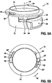
Fig. 5 shows an embodiment of a tool according to the present invention, in a perspective view (Fig. 5A ) and in a top view (Fig. 5B ), -
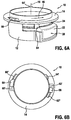
Fig. 6 shows the tool according to the present invention in a second position, in a perspective view (Fig. 6A ) and in a top view (Fig. 6B ), -
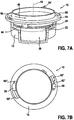
Fig. 7 shows the tool according to the present invention in a third position, in a perspective view (Fig. 7A ) and in a top view (Fig. 7B ), -
Fig. 8 shows a further perspective view of the tool according to the present invention in a fourth position, -
Fig. 9 shows an even further perspective view of the tool according to the present invention in a fifth position, and -
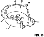
Fig. 10 shows a perspective view of a base portion of the tool. -
Figs. 1 and 2 illustrate the principle design of atransducer housing 20 which may be opened and closed with thetool 10 according to the present invention. Thetool 10 will be described further below with reference toFigs. 5 to 9 . For a better understanding of the reader the principle design of thetransducer housing 20 that may be opened and closed with thetool 10 shall be explained first. - As illustrated in
Fig. 1 thetransducer housing 20 comprises two housing parts, abase body 22 and alid 24. Thebase body 22 and thelid 24 form two half-shells of thetransducer housing 20 to provide an encapsulated volume inside thetransducer housing 20. In practice, several transducers, sensors and peripheral electronic devices of an obstetric ultrasonography device or an electronic fetal monitor (EFM) are arranged in this encapsulated volume. - A
rotational coupling 26, which is in detail illustrated inFigs. 3A and 3B , is used as a connection means to connect thelid 24 with thebase body 22. This rotational coupling is, according to the herein presented embodiment, realized as abayonet mount 26. Thisbayonet mount 26 comprisesseveral undercuts 28 that are arranged on the bottom side of thelid 24 and a plurality ofcorresponding bayonet noses 30 that are arranged on a circumferentialinner wall 32 of thebase body 22. - As it is schematically illustrated in
Fig. 3A byarrow 34 thelid 24 may be coupled with thebase body 22 by a clockwise rotation of thelid 24 relative to thebase body 22 of thetransducer housing 20. Upon this rotation theundercuts 28 engage with thebayonet noses 30 to form a mechanically secure but releasable connection between thelid 24 and thebase body 22.Fig. 3B illustrates the closed position of thebayonet mount 26. - It is to be understood that the
bayonet mount 26 may also be inverted compared to the illustrated example. Thebayonet noses 30 could also be arranged on thelid 24 and the undercutmembers 28 could be arranged on theinner wall 32 of thebase body 22. Likewise it would also be possible to invert the alignment of the undercutmembers 28 so that thebayonet mount 26 would be closed upon a counter-clockwise rotational movement of thelid 24 relative to thebase body 22, and opened upon a clockwise rotational movement of thelid 24 relative to thebase body 22. - According to an embodiment the undercut
members 28 and thebayonet noses 30 may be arranged asymmetrically. This means that the distances between thebayonet noses 30 may (slightly) differ. Accordingly, thelid 24 may be attached to thebase body 22 in only one correct position. This serves as a poka-yoke feature supporting the user to correctly attach thelid 24 to thebase body 22 of thetransducer housing 20. - As it is shown in
Fig. 1 the base body of the transducer housing preferably has a substantially cylindrical shape. In correspondence thereto thelid 24 has, in a plane view (seeFig. 2 ), a substantially circular shape. However, parts of thebase body 22 and parts of thelid 24 differ from said substantially cylindrical or substantially circular shape, respectively. These parts of thebase body 22 and thelid 24 are indicated inFigs. 1 and 2 byreference numerals - The
part 36 of thebase body 22 is realized as a kind of projection of the cylindrical main part of thebase body 22. Saidprojection 36 comprises two planar contact surfaces 40 that may be used as counter supports for contacting corresponding contact surfaces of thetool 10 and preventing a rotational movement of thebase body 22 within the tool 110. - Similarly, the
projection 38 that is arranged on one side of thelid 24 comprises twocontact areas 42 on its lateral sides. Thesecontact areas 42 can be contacted by a driving pin of thetool 10 in order to exert a force onto thelid 24 for rotating thelid 24 relative to thebase body 22 of thetransducer housing 20 to open or close thebayonet mount 26. The detailed principle how thebayonet mount 26 is opened with thetool 10, will be explained in detail further below with reference toFigs. 5 to 9 . - The described
contact areas 42 of thelid 24 preferably have a rounded, convex shape. Even though this is not a mandatory feature such a rounded, convex shape prevents that thelid 24 may be rotated by hand or by using a conventional tool. No means or levers are integrated into thelid 24 that could be used to easily rotate thelid 24 by hand in order to open thebayonet mount 26. Thebayonet mount 26 shall furthermore be tight enough so that one cannot exert a sufficient momentum onto thelid 24 by hand. Therefore, thelid 24 can only be opened using thetool 10. This shall be especially ensured due to the strong regulations in the medical field that stipulate that a medical device may not be opened by any unauthorized person. -
Fig. 4 again shows respective views of thetransducer housing 20, whereinFig. 4A shows thelid 24 in its closed position, andFig. 4B shows thelid 24 in its open position. It is clear that the position of thebayonet mount 26 illustrated inFig. 3B corresponds to the closed position of the lid 24 (illustrated inFig. 4A ) and the open position of thebayonet mount 26 illustrated inFig. 3A corresponds to the open position of the lid 24 (illustrated inFig. 4B ). FromFig. 4 it may be further seen that thetransducer housing 20 may compriseseveral connectors 44. Theseconnectors 44 can have different technical functions. For example, a power supply may be connected to the transducer. On the other hand, these connectors could serve as a connection to a base station in order to transmit the gained ultrasonic transducer signals. It shall be noted that the transducers inside thetransducer housing 20 may be connected to such a base station either via a wireless connection or via a hard-wired connection. - In the following the details of the
tool 10 according to the present invention will be presented. As illustrated inFig. 5A thetool 10 comprises abase portion 12 and anupper portion 14. Thebase portion 12 has the form of a bowl that is configured to receive thetransducer housing 20. Since the shape of said bowl is adapted to the shape of thebase body 22 of thetransducer housing 20, thebase portion 12 of thetool 10 prevents a rotation of thebase body 22 of thetransducer housing 20 within thetool 10 around anaxial direction 16. This form fit also prevents a relative movement of thebase body 22 of thetransducer housing 20 within thebase portion 12 of thetool 10 along a radial direction 18. -
Fig. 10 shows an enlarged view of thebase portion 12 of thetool 10. It can be seen that thebase portion 12 comprises aninner wall 48 that is adapted to theouter wall 50 of thebase body 22 of the transducer housing 20 (compare toFig. 1 ). Thisinner wall 48 preferably has a cylindricallycurved surface area 52. However, parts of saidinner wall 48 deviate from the cylindrical shape and comprise aplanar contact surface 54 which is adapted to contact thecontact surface 40 of thetransducer housing 20 for preventing a rotation of thebase body 22 of thetransducer housing 20 relative to thebase portion 12 of thetool 10 around the axial direction 16 (along the circumferential direction 46). - The
base portion 12 further comprises to guiding pins, afirst guiding pin 56 and a second guiding pin 58 (see e.g.Fig. 5B ). The first and the second guiding pins 56, 58 are also denoted asfirst engagement member 56 andthird engagement member 58. It is to be noted that, depending on the size, only oneengagement member such engagement members - The two guiding
pins base portion 12 with the tool'supper portion 14. Theupper portion 14 thereto comprises two recesses, afirst recess 60 and a second recess 62 (see e.g.Fig. 5B ). These first andsecond recesses second engagement member 60 andfourth engagement member 62. - As illustrated in
Fig. 5B thefirst guiding pin 56 engages with thefirst recess 60, whereas thesecond guiding pin 58 engages with thesecond recess 62. The guiding pins 56, 58 as well as therecesses upper portion 14 onto thebase portion 12, since an incorrect attachment is prevented. The larger guiding pin 56 (first engagement member) can only engage with the larger recess 60 (second engagement member) and the smaller guiding pin 58 (third engagement member) can only engage with the smaller recess 62 (fourth engagement member). - On the one hand, the engagement between the guiding pins 56, 58 and the
recesses upper portion 14 relative to thebase portion 12 and, on the other hand, prevents a movement of theupper portion 14 to thebase portion 12 along theaxial direction 16 during opening and/or closing thelid 24 of thetransducer housing 20. - In order to open the
bayonet mount 26 of thetransducer housing 20 the tool'supper portion 14 is simply rotated relative to the tool'sbase portion 12 around the axial direction 16 (along the circumferential direction 46). Upon this rotational movement a drivingpin 64, that is arranged on the tool'supper portion 14, contacts thelid 24 of thetransducer housing 20 and causes thelid 24 to rotate as well (synchronously with the rotational movement of the tool's upper portion 14). Since thebase body 22 of thetransducer housing 20 is fixed within the tool'sbase portion 12, this rotational movement of thelid 24 opens thebayonet mount 26. - The driving
pin 64 is configured to establish a form fit with thecontact area 42 of thelid 24. In order to establish this form fit the drivingpin 64 preferably comprises a drivingarea 66 that has a concave shape (corresponding to the convex shape of thecontact area 42 of thelid 24; compare toFig. 2 ). -
Figs. 5 to 7 show different snapshots at subsequent points in time for illustrating the technical principle of thetool 10 during opening thelid 24 of thetransducer housing 20.Figs. 5A and 5B show the starting position after the tool'supper portion 14 has been attached to the tool'sbase portion 12. In this position the drivingpin 64 does not contact the lid 24 (seeFig. 5A ). - As it can be seen in
Fig. 5B thelarger guiding pin 56 is in this situation arranged in an insertion section 60' of therecess 60 and thesmaller guiding pin 58 is arranged in an insertion section 62' of therecess 62. Both recesses 60, 62 have the form similar to an L and comprise larger insertion sections 60', 62' and smaller (narrower)sections 60", 62", which are herein denoted as lockingsections 60", 62". If the guiding pins 56, 58 are arranged within the insertion sections 60', 62' of therecesses upper portion 14 is still free to move inaxial direction 16 relative to the tool'sbase portion 12. As soon as the guiding pins 56, 58 are led into the lockingsections 60", 62" of therecesses 60, 62 (upon a rotation of theupper portion 14 around the axial direction 16), the guiding pins 56, 58 clamp the tool'supper portion 14 and prevent a movement of theupper portion 14 relative to thebase portion 12 inaxial direction 16. It is to be noted that in this case the tool'saxial direction 16 falls together with the axial direction of thetransducer housing 20. - In the starting position shown in
Figs. 5A and 5B the drivingpin 64 does not contact thelid 24 and the two guidingpins Fig. 5B ). If the tool'supper portion 14 is then rotated counter-clockwise around theaxial direction 16, the drivingpin 64 will contact the lid 24 (seeFig. 6A ), wherein a form fit between the drivingarea 66 of the drivingpin 64 and thecontact area 42 of thelid 24 is established. In this situation a relative movement of the tool'supper portion 14 along theaxial direction 16 is prevented through the engagement between the guiding pins 56, 58 and therecesses 60, 62 (seeFig. 6B ). - As it can be seen in
Fig. 6B the guiding pins 56, 58 are then already arranged within the lockingsections 60", 62" of therecesses sections 60", 62" relative to the drivingpin 64 is chosen such that the guiding pins 56, 58 of thebase portion 12 reach the lockingsections 60", 62" before the drivingarea 66 of the drivingpin 64 contacts thecontact area 42 of thelid 24 during a rotational movement of the tool'supper portion 14 around theaxial direction 16. In other words, theupper portion 14 is fixed inaxial direction 16 before the drivingpin 64 reaches thelid 24 of thetransducer housing 20. The drivingpin 64 does therefore not only exert a force incircumferential direction 46 onto thelid 24, but is also pressed inaxial direction 16 onto thelid 24. This ensures that the drivingpin 64 does not simply slip over thelid 24 of thetransducer housing 20 without opening it. -
Fig. 7 shows the situation, where the tool'supper portion 14 has been fully turned around theaxial direction 16. The lid 24 (the bayonet mount 26) is then open and the two guidingpins sections 60", 62" of therecesses transducer housing 20 the tool'supper portion 14 simply has to be turned back (in a clockwise manner) so that theupper portion 14 may be decoupled from the tool'sbase portion 12 and thetransducer housing 20 can be manually unloaded. - In summary, a user simply has to enter the
transducer housing 20 into the tool'sbase portion 12, then attach the tool'supper portion 14 thereto, and then turn theupper portion 14 relative tobase portion 12. As soon as thebayonet mount 26 of thetransducer housing 20 is open, theupper portion 14 may be turned back, decoupled from thebase portion 12, and the openedtransducer housing 20 may be manually unloaded. - Closing the
bayonet mount 26 of thetransducer housing 20 may be carried out in quite a similar way by using thesame tool 10. The tool'supper portion 14 only has to be turned upside-down. In other words, the tool'supper portion 14 has to be flipped over. This situation is illustrated inFigs. 8 and 9 . - Compared to the situations shown in
Figs. 5 to 7 , the tool'supper portion 14 is turned upside-down inFigs. 8 and 9 . A second driving pin 64' is then used to close thelid 24 of thetransducer housing 20 upon a rotational movement of the tool'supper portion 14 in a clockwise manner (indicated by arrow 46'). This second driving pin 64' is arranged on an opposite side of theupper portion 14 and faces in a direction opposite to thefirst driving pin 64, which had been used for opening thelid 24. The second driving pin 64' comprises a second driving area 66' that faces in a direction opposite to thefirst driving area 66 of thefirst driving pin 64. Closing thelid 24 therefore works quite the same as opening it, except the difference that now the second driving pin 64' (and not the first driving pin 64) faces downwards, towards thetransducer housing 20 and that the tool'supper portion 14 is rotated clockwise (instead of counter-clockwise). - Finally, it shall be stated that the
tool 10 could of course also be constructed vice versa so that a clockwise movement of the tool'supper portion 14 would cause thelid 24 to open and a contrary counter-clockwise movement of the tool'supper portion 14 would cause thelid 24 to close. - While the invention has been illustrated and described in detail in the drawings and foregoing description, such illustration and description are to be considered illustrative or exemplary and not restrictive; the invention is not limited to the disclosed embodiments. Other variations to the disclosed embodiments can be understood and effected by those skilled in the art in practicing the claimed invention, from a study of the drawings, the disclosure, and the appended claims.
- In the claims, the word "comprising" does not exclude other elements or steps, and the indefinite article "a" or "an" does not exclude a plurality. A single element or other unit may fulfill the functions of several items recited in the claims. The mere fact that certain measures are recited in mutually different dependent claims does not indicate that a combination of these measures cannot be used to advantage.
- Any reference signs in the claims should not be construed as limiting the scope.
wherein the upper portion further comprises a driving pin having a driving area for contacting a corresponding contact area of the lid of the transducer housing for causing the lid of the transducer housing to move relative to the base body of the transducer housing in order to open or close the rotational coupling upon a rotational movement of the upper portion relative to the base portion around the axial direction; and
wherein an engagement of the second engagement member with the first engagement member prevents a movement of the upper portion and the driving pin relative to the base portion along the axial direction during a contact between the driving area of the driving pin and the contact area of the lid of the transducer housing.
wherein the lid comprises a contact area that is adapted to be contacted by a driving pin of the tool according to claim 1 in order to open or close the rotational coupling upon rotation of the lid relative to the base body around the axial direction, and
wherein the base body has a shape that is adapted to a base portion of said tool for preventing a rotation of the base body relative to the base portion of the tool around the axial direction.
Claims (15)
- Tool for opening and closing a transducer housing (20) having two housing parts, a base body (22) and a lid (24), that are coupleable with each other via a rotational coupling (26), wherein the tool (10) comprises:- a base portion (12) forming a bowl for receiving the transducer housing (20) and preventing a rotation of the base body (22) of the transducer housing (20) relative to the base portion (12) of the tool (10) around an axial direction (16) of the tool (10); and- an upper portion (14) that is separate from the base portion (12) and may be attached to the base portion (12), wherein a movement of the upper portion (14) relative to the base portion (12) in a radial direction (18), which is perpendicular to the axial direction (16), is mechanically prevented when the upper portion (14) is attached to the base portion (12);wherein the base portion (12) comprises a first engagement member (56) and wherein the upper portion (14) comprises a second engagement member (60) which engages with the first engagement member (56) when the upper portion (14) is attached to the base portion (12),
wherein the upper portion (14) further comprises a driving pin (64) having a driving area (66) for contacting a corresponding contact area (42) of the lid (24) of the transducer housing (20) for causing the lid (24) of the transducer housing (20) to move relative to the base body (22) of the transducer housing (20) in order to open or close the rotational coupling (26) upon a rotational movement of the upper portion (14) relative to the base portion (12) around the axial direction (16); and
wherein an engagement of the second engagement member (60) with the first engagement member (56) prevents a movement of the upper portion (14) and the driving pin (64) relative to the base portion (12) along the axial direction (16) during a contact between the driving area (66) of the driving pin (64) and the contact area (42) of the lid (24) of the transducer housing (20). - Tool according to claim 1, wherein the base portion (12) comprises an inner wall (48) and the upper portion (14) comprises an outer wall that faces the inner wall (48) of the base portion (12) when the upper portion (14) and the base portion (12) are coupled with each other.
- Tool according to claim 2, wherein at least a part of said inner wall (48) of the base portion (12) forms a form fit with at least a part of the outer wall of the upper portion (14), when the upper portion (14) and the base portion (12) are coupled with each other, for preventing a movement of the upper portion (14) relative to the base portion (12) in the radial direction (18).
- Tool according to claim 2, wherein a rotation of the base body (22) of the transducer housing (20) relative to the base portion (12) of the tool (10) around the axial direction (16) is prevented through a form fit between the inner wall (48) of the base portion (12) of the tool (10) and an outer surface (50) of the transducer housing (20).
- Tool according to claim 2, wherein the inner wall (48) of the base portion (12) has a cylindrically curved surface area (52), wherein parts of said inner wall (48) deviate from the cylindrical shape and comprise a planar contact surface (54) for contacting a corresponding contact surface (40) of the transducer housing (20) and preventing a rotation of the base body (22) of the transducer housing (20) relative to the base portion (12) of the tool (10) around the axial direction (16).
- Tool according to claim 1, wherein the second engagement member (60) is a recess in the upper portion (14), and wherein the first engagement member (56) is a guiding pin which engages with said recess (60) when the upper portion (14) and the base portion (12) are coupled with each other.
- Tool according to claim 6, wherein the recess (60) comprises an insertion section (60') and an adjacent locking section (60"), wherein the insertion section (60') is larger than the locking section (60"), wherein the guiding pin (56) may be inserted into the insertion section (60'), and wherein the guiding pin (56) may be guided into the locking section (60") upon a rotational movement of the upper portion (14) relative to the base portion (12) around the axial direction (16) for clamping the guiding pin (56) in axial direction (16).
- Tool according to claim 1, wherein the base portion (12) comprises a third engagement member (58) and wherein the upper portion (14) comprises a fourth engagement member (62) which engages with the third engagement member (58) when the upper portion (14) and the base portion (12) are coupled with each other.
- Tool according to claim 1, wherein the driving area (66) of the driving pin (64) has a concave shape.
- Tool according to claim 1, wherein the driving area (66) of the driving pin (64) is configured to establish a form fit with the contact area (42) of the lid (24) of the transducer housing (20) upon contacting said contact area (42) during the rotational movement of the upper portion (14) relative to the base portion (12) around the axial direction.
- Tool according to claim 1, wherein the upper portion comprises two driving pins (64, 64'), a first driving pin (64) with a first driving area (66) for opening the rotational coupling (26) of the transducer housing (20) upon a rotational movement of the upper portion (14) relative to the base portion (12) around the axial direction (16), and a second driving pin (64') with a second driving area (66') for closing the rotational coupling (26) of the transducer housing (20) upon an oppositely oriented rotational movement of the upper portion (14) relative to the base portion (12) around the axial direction (16).
- Tool according to claim 11, wherein the first driving pin (64) and the second driving pin (64') are arranged on opposite sides of the upper portion (14), and wherein the first driving area (66) and the second driving area (66') face in opposite directions.
- Kit comprising:- a tool (10) according to any of claims 1 to 12, and- a transducer housing (20) having two housing parts, a base body (22) and a lid (24), that are coupleable with each other via a rotational coupling (26), wherein the lid (24) comprises a contact area (42) that is adapted to be contacted by a driving pin (64) of the tool in order (10) to open or close the transducer housing (20).
- A transducer housing comprising:- a base body (22), and- a lid (24),wherein the base body (22) and the lid (24) are coupleable with each other via a rotational coupling (26),
wherein the lid (24) comprises a contact area (42) that is adapted to be contacted by a driving pin (64) of the tool (10) according to claim 1 in order to open or close the rotational coupling (26) upon rotation of the lid (24) relative to the base body (22) around the axial direction (16), and
wherein the base body (22) has a shape that is adapted to a base portion (12) of said tool (10) for preventing a rotation of the base body (22) relative to the base portion (12) of the tool (10) around the axial direction (16). - Transducer housing according to claim 14, wherein the rotational coupling (26) is a releasable bayonet mount.
Applications Claiming Priority (2)
| Application Number | Priority Date | Filing Date | Title |
|---|---|---|---|
| US201261708716P | 2012-10-02 | 2012-10-02 | |
| PCT/IB2013/058855 WO2014053958A1 (en) | 2012-10-02 | 2013-09-25 | Tool for opening and closing a transducer housing |
Publications (2)
| Publication Number | Publication Date |
|---|---|
| EP2903529A1 EP2903529A1 (en) | 2015-08-12 |
| EP2903529B1 true EP2903529B1 (en) | 2016-07-13 |
Family
ID=49780110
Family Applications (1)
| Application Number | Title | Priority Date | Filing Date |
|---|---|---|---|
| EP13808219.3A Active EP2903529B1 (en) | 2012-10-02 | 2013-09-25 | Tool for opening and closing a transducer housing |
Country Status (5)
| Country | Link |
|---|---|
| US (1) | US9743907B2 (en) |
| EP (1) | EP2903529B1 (en) |
| JP (1) | JP6170163B2 (en) |
| CN (1) | CN104703545B (en) |
| WO (1) | WO2014053958A1 (en) |
Families Citing this family (2)
| Publication number | Priority date | Publication date | Assignee | Title |
|---|---|---|---|---|
| CN104739443B (en) * | 2013-12-30 | 2018-06-26 | 深圳迈瑞生物医疗电子股份有限公司 | A kind of medical external supersonic probe and diasonograph |
| CN114305486A (en) * | 2020-09-30 | 2022-04-12 | 通用电气精准医疗有限责任公司 | Scanning assembly for ultrasonic imaging device and ultrasonic imaging device |
Family Cites Families (15)
| Publication number | Priority date | Publication date | Assignee | Title |
|---|---|---|---|---|
| US3625093A (en) | 1969-06-30 | 1971-12-07 | Fimecor Fine Mecanique Sa | Machine for rotatably driving the bottom of a watch-casing or the bottom of a measuring apparatus |
| CH1383273A4 (en) | 1973-09-27 | 1975-10-31 | ||
| DE3825047A1 (en) | 1987-10-19 | 1989-04-27 | Siemens Ag | SENSOR FOR DETECTING THE LIQUID LEVEL IN A CONTAINER |
| DE9004824U1 (en) * | 1990-04-27 | 1990-08-02 | Hewlett-Packard Gmbh, 7030 Boeblingen, De | |
| DE9421095U1 (en) | 1994-07-07 | 1995-07-13 | Wtw Weilheim | Integrated analyzer for determining the gas consumption of matter |
| EP0749722A3 (en) | 1995-06-22 | 1997-04-16 | Hewlett Packard Co | Handheld transthoracic rotatable ultrasound transducer |
| US5882300A (en) * | 1996-11-07 | 1999-03-16 | Spacelabs Medical, Inc. | Wireless patient monitoring apparatus using inductive coupling |
| US6635019B2 (en) * | 2001-08-14 | 2003-10-21 | Koninklijke Philips Electronics Nv | Scanhead assembly for ultrasonic imaging having an integral beamformer and demountable array |
| CA2520797C (en) | 2003-04-09 | 2008-12-23 | Korea Alpaline Co. Ltd. | Multi-layered container with intermediate lid |
| JP4503318B2 (en) * | 2004-03-16 | 2010-07-14 | 株式会社エー・アンド・デイ | Health measuring device |
| KR20090096058A (en) | 2008-03-07 | 2009-09-10 | 주식회사 락앤락 | Stackable container |
| US8038025B2 (en) | 2008-08-07 | 2011-10-18 | Becton, Dickinson And Company | Medical waste container hinged lid |
| US9222652B2 (en) * | 2010-07-21 | 2015-12-29 | Koninklijke Philips N.V. | Lighting module as a tool for connecting/disconnecting another lighting module |
| US9717412B2 (en) * | 2010-11-05 | 2017-08-01 | Gary And Mary West Health Institute | Wireless fetal monitoring system |
| CN202221323U (en) * | 2011-07-15 | 2012-05-16 | 上海一诺仪表有限公司 | Casing structure of ultrasonic energy converter |
-
2013
- 2013-09-25 WO PCT/IB2013/058855 patent/WO2014053958A1/en active Application Filing
- 2013-09-25 EP EP13808219.3A patent/EP2903529B1/en active Active
- 2013-09-25 CN CN201380051888.5A patent/CN104703545B/en active Active
- 2013-09-25 JP JP2015535137A patent/JP6170163B2/en active Active
- 2013-09-25 US US14/432,495 patent/US9743907B2/en active Active
Also Published As
| Publication number | Publication date |
|---|---|
| US9743907B2 (en) | 2017-08-29 |
| CN104703545A (en) | 2015-06-10 |
| EP2903529A1 (en) | 2015-08-12 |
| US20150216501A1 (en) | 2015-08-06 |
| WO2014053958A1 (en) | 2014-04-10 |
| JP6170163B2 (en) | 2017-07-26 |
| CN104703545B (en) | 2017-06-20 |
| JP2015532139A (en) | 2015-11-09 |
Similar Documents
| Publication | Publication Date | Title |
|---|---|---|
| JP3190140U (en) | Massage disc assembly positioning structure for massage | |
| CN101730516B (en) | Storage and dispensing devices for adminsistration of oral transmucosal dosage forms | |
| EP2903529B1 (en) | Tool for opening and closing a transducer housing | |
| JP2007535338A (en) | Device for applying and removing occluding means to the end portion of a tubular element and its use in peritoneal dialysis | |
| US20130317408A1 (en) | Medical device for extracorporeal blood treatment comprising plural sensor units | |
| GB2571035A (en) | Packages with monitoring devices | |
| TW202114587A (en) | Ear thermometer with a probe cover ejection device | |
| KR101633618B1 (en) | Adapter for surgical robot | |
| ES2583904A2 (en) | Dental scan abutment and procedure for its assembly and fixation to a dental implant or a replica of it (Machine-translation by Google Translate, not legally binding) | |
| CN208511059U (en) | Energy converter locking device | |
| JP5048414B2 (en) | Infusion device installation tool | |
| Buendía-Eisman et al. | Generalized annular granuloma: response to isotretinoin. | |
| CN213097975U (en) | Auxiliary bracket for ultrasound department examination | |
| KR102080853B1 (en) | A detachable device for breast cancer self diagnosis | |
| CN210078306U (en) | Medicine discharging structure suitable for medicines of different sizes | |
| CN112294277A (en) | Multifunctional nursing system for department of cardiology | |
| JP6483664B2 (en) | Button type battery storage and medical electronic device | |
| CN213642755U (en) | Dialysis tube positioning and binding belt for nephrology department | |
| Yahchouchy et al. | Recurrent idiopathic small bowel volvulus during pregnancy. | |
| TWI376222B (en) | Medicine storage device | |
| US10898124B1 (en) | Wearable device for recording motion data | |
| TWM485730U (en) | Health-care medicine box with automatic reminder medication administration function | |
| WO2023076067A1 (en) | Automated urinary output monitoring system | |
| JP6444695B2 (en) | External defibrillator | |
| KR101871981B1 (en) | X-ray generator for securing systems and devices containing them |
Legal Events
| Date | Code | Title | Description |
|---|---|---|---|
| PUAI | Public reference made under article 153(3) epc to a published international application that has entered the european phase |
Free format text: ORIGINAL CODE: 0009012 |
|
| 17P | Request for examination filed |
Effective date: 20150504 |
|
| AK | Designated contracting states |
Kind code of ref document: A1 Designated state(s): AL AT BE BG CH CY CZ DE DK EE ES FI FR GB GR HR HU IE IS IT LI LT LU LV MC MK MT NL NO PL PT RO RS SE SI SK SM TR |
|
| AX | Request for extension of the european patent |
Extension state: BA ME |
|
| 17Q | First examination report despatched |
Effective date: 20151014 |
|
| DAX | Request for extension of the european patent (deleted) | ||
| GRAP | Despatch of communication of intention to grant a patent |
Free format text: ORIGINAL CODE: EPIDOSNIGR1 |
|
| INTG | Intention to grant announced |
Effective date: 20160425 |
|
| GRAS | Grant fee paid |
Free format text: ORIGINAL CODE: EPIDOSNIGR3 |
|
| GRAA | (expected) grant |
Free format text: ORIGINAL CODE: 0009210 |
|
| AK | Designated contracting states |
Kind code of ref document: B1 Designated state(s): AL AT BE BG CH CY CZ DE DK EE ES FI FR GB GR HR HU IE IS IT LI LT LU LV MC MK MT NL NO PL PT RO RS SE SI SK SM TR |
|
| REG | Reference to a national code |
Ref country code: GB Ref legal event code: FG4D |
|
| REG | Reference to a national code |
Ref country code: AT Ref legal event code: REF Ref document number: 811619 Country of ref document: AT Kind code of ref document: T Effective date: 20160715 Ref country code: CH Ref legal event code: EP |
|
| REG | Reference to a national code |
Ref country code: IE Ref legal event code: FG4D |
|
| REG | Reference to a national code |
Ref country code: DE Ref legal event code: R096 Ref document number: 602013009461 Country of ref document: DE |
|
| REG | Reference to a national code |
Ref country code: FR Ref legal event code: PLFP Year of fee payment: 4 |
|
| REG | Reference to a national code |
Ref country code: LT Ref legal event code: MG4D |
|
| REG | Reference to a national code |
Ref country code: NL Ref legal event code: MP Effective date: 20160713 |
|
| REG | Reference to a national code |
Ref country code: AT Ref legal event code: MK05 Ref document number: 811619 Country of ref document: AT Kind code of ref document: T Effective date: 20160713 |
|
| PG25 | Lapsed in a contracting state [announced via postgrant information from national office to epo] |
Ref country code: LT Free format text: LAPSE BECAUSE OF FAILURE TO SUBMIT A TRANSLATION OF THE DESCRIPTION OR TO PAY THE FEE WITHIN THE PRESCRIBED TIME-LIMIT Effective date: 20160713 Ref country code: NL Free format text: LAPSE BECAUSE OF FAILURE TO SUBMIT A TRANSLATION OF THE DESCRIPTION OR TO PAY THE FEE WITHIN THE PRESCRIBED TIME-LIMIT Effective date: 20160713 Ref country code: NO Free format text: LAPSE BECAUSE OF FAILURE TO SUBMIT A TRANSLATION OF THE DESCRIPTION OR TO PAY THE FEE WITHIN THE PRESCRIBED TIME-LIMIT Effective date: 20161013 Ref country code: IT Free format text: LAPSE BECAUSE OF FAILURE TO SUBMIT A TRANSLATION OF THE DESCRIPTION OR TO PAY THE FEE WITHIN THE PRESCRIBED TIME-LIMIT Effective date: 20160713 Ref country code: IS Free format text: LAPSE BECAUSE OF FAILURE TO SUBMIT A TRANSLATION OF THE DESCRIPTION OR TO PAY THE FEE WITHIN THE PRESCRIBED TIME-LIMIT Effective date: 20161113 Ref country code: RS Free format text: LAPSE BECAUSE OF FAILURE TO SUBMIT A TRANSLATION OF THE DESCRIPTION OR TO PAY THE FEE WITHIN THE PRESCRIBED TIME-LIMIT Effective date: 20160713 Ref country code: HR Free format text: LAPSE BECAUSE OF FAILURE TO SUBMIT A TRANSLATION OF THE DESCRIPTION OR TO PAY THE FEE WITHIN THE PRESCRIBED TIME-LIMIT Effective date: 20160713 Ref country code: FI Free format text: LAPSE BECAUSE OF FAILURE TO SUBMIT A TRANSLATION OF THE DESCRIPTION OR TO PAY THE FEE WITHIN THE PRESCRIBED TIME-LIMIT Effective date: 20160713 |
|
| PG25 | Lapsed in a contracting state [announced via postgrant information from national office to epo] |
Ref country code: LV Free format text: LAPSE BECAUSE OF FAILURE TO SUBMIT A TRANSLATION OF THE DESCRIPTION OR TO PAY THE FEE WITHIN THE PRESCRIBED TIME-LIMIT Effective date: 20160713 Ref country code: BE Free format text: LAPSE BECAUSE OF NON-PAYMENT OF DUE FEES Effective date: 20160713 Ref country code: SE Free format text: LAPSE BECAUSE OF FAILURE TO SUBMIT A TRANSLATION OF THE DESCRIPTION OR TO PAY THE FEE WITHIN THE PRESCRIBED TIME-LIMIT Effective date: 20160713 Ref country code: GR Free format text: LAPSE BECAUSE OF FAILURE TO SUBMIT A TRANSLATION OF THE DESCRIPTION OR TO PAY THE FEE WITHIN THE PRESCRIBED TIME-LIMIT Effective date: 20161014 Ref country code: ES Free format text: LAPSE BECAUSE OF FAILURE TO SUBMIT A TRANSLATION OF THE DESCRIPTION OR TO PAY THE FEE WITHIN THE PRESCRIBED TIME-LIMIT Effective date: 20160713 Ref country code: PL Free format text: LAPSE BECAUSE OF FAILURE TO SUBMIT A TRANSLATION OF THE DESCRIPTION OR TO PAY THE FEE WITHIN THE PRESCRIBED TIME-LIMIT Effective date: 20160713 Ref country code: AT Free format text: LAPSE BECAUSE OF FAILURE TO SUBMIT A TRANSLATION OF THE DESCRIPTION OR TO PAY THE FEE WITHIN THE PRESCRIBED TIME-LIMIT Effective date: 20160713 Ref country code: PT Free format text: LAPSE BECAUSE OF FAILURE TO SUBMIT A TRANSLATION OF THE DESCRIPTION OR TO PAY THE FEE WITHIN THE PRESCRIBED TIME-LIMIT Effective date: 20161114 |
|
| REG | Reference to a national code |
Ref country code: DE Ref legal event code: R097 Ref document number: 602013009461 Country of ref document: DE |
|
| PG25 | Lapsed in a contracting state [announced via postgrant information from national office to epo] |
Ref country code: EE Free format text: LAPSE BECAUSE OF FAILURE TO SUBMIT A TRANSLATION OF THE DESCRIPTION OR TO PAY THE FEE WITHIN THE PRESCRIBED TIME-LIMIT Effective date: 20160713 Ref country code: RO Free format text: LAPSE BECAUSE OF FAILURE TO SUBMIT A TRANSLATION OF THE DESCRIPTION OR TO PAY THE FEE WITHIN THE PRESCRIBED TIME-LIMIT Effective date: 20160713 Ref country code: MC Free format text: LAPSE BECAUSE OF FAILURE TO SUBMIT A TRANSLATION OF THE DESCRIPTION OR TO PAY THE FEE WITHIN THE PRESCRIBED TIME-LIMIT Effective date: 20160713 |
|
| REG | Reference to a national code |
Ref country code: CH Ref legal event code: PL |
|
| PLBE | No opposition filed within time limit |
Free format text: ORIGINAL CODE: 0009261 |
|
| STAA | Information on the status of an ep patent application or granted ep patent |
Free format text: STATUS: NO OPPOSITION FILED WITHIN TIME LIMIT |
|
| PG25 | Lapsed in a contracting state [announced via postgrant information from national office to epo] |
Ref country code: BG Free format text: LAPSE BECAUSE OF FAILURE TO SUBMIT A TRANSLATION OF THE DESCRIPTION OR TO PAY THE FEE WITHIN THE PRESCRIBED TIME-LIMIT Effective date: 20161013 Ref country code: CZ Free format text: LAPSE BECAUSE OF FAILURE TO SUBMIT A TRANSLATION OF THE DESCRIPTION OR TO PAY THE FEE WITHIN THE PRESCRIBED TIME-LIMIT Effective date: 20160713 Ref country code: SK Free format text: LAPSE BECAUSE OF FAILURE TO SUBMIT A TRANSLATION OF THE DESCRIPTION OR TO PAY THE FEE WITHIN THE PRESCRIBED TIME-LIMIT Effective date: 20160713 Ref country code: DK Free format text: LAPSE BECAUSE OF FAILURE TO SUBMIT A TRANSLATION OF THE DESCRIPTION OR TO PAY THE FEE WITHIN THE PRESCRIBED TIME-LIMIT Effective date: 20160713 Ref country code: SM Free format text: LAPSE BECAUSE OF FAILURE TO SUBMIT A TRANSLATION OF THE DESCRIPTION OR TO PAY THE FEE WITHIN THE PRESCRIBED TIME-LIMIT Effective date: 20160713 |
|
| 26N | No opposition filed |
Effective date: 20170418 |
|
| REG | Reference to a national code |
Ref country code: IE Ref legal event code: MM4A |
|
| PG25 | Lapsed in a contracting state [announced via postgrant information from national office to epo] |
Ref country code: IE Free format text: LAPSE BECAUSE OF NON-PAYMENT OF DUE FEES Effective date: 20160925 Ref country code: CH Free format text: LAPSE BECAUSE OF NON-PAYMENT OF DUE FEES Effective date: 20160930 Ref country code: LI Free format text: LAPSE BECAUSE OF NON-PAYMENT OF DUE FEES Effective date: 20160930 |
|
| PG25 | Lapsed in a contracting state [announced via postgrant information from national office to epo] |
Ref country code: LU Free format text: LAPSE BECAUSE OF NON-PAYMENT OF DUE FEES Effective date: 20160925 Ref country code: SI Free format text: LAPSE BECAUSE OF FAILURE TO SUBMIT A TRANSLATION OF THE DESCRIPTION OR TO PAY THE FEE WITHIN THE PRESCRIBED TIME-LIMIT Effective date: 20160713 |
|
| REG | Reference to a national code |
Ref country code: FR Ref legal event code: PLFP Year of fee payment: 5 |
|
| PG25 | Lapsed in a contracting state [announced via postgrant information from national office to epo] |
Ref country code: HU Free format text: LAPSE BECAUSE OF FAILURE TO SUBMIT A TRANSLATION OF THE DESCRIPTION OR TO PAY THE FEE WITHIN THE PRESCRIBED TIME-LIMIT; INVALID AB INITIO Effective date: 20130925 |
|
| PG25 | Lapsed in a contracting state [announced via postgrant information from national office to epo] |
Ref country code: CY Free format text: LAPSE BECAUSE OF FAILURE TO SUBMIT A TRANSLATION OF THE DESCRIPTION OR TO PAY THE FEE WITHIN THE PRESCRIBED TIME-LIMIT Effective date: 20160713 Ref country code: MT Free format text: LAPSE BECAUSE OF NON-PAYMENT OF DUE FEES Effective date: 20160930 Ref country code: MK Free format text: LAPSE BECAUSE OF FAILURE TO SUBMIT A TRANSLATION OF THE DESCRIPTION OR TO PAY THE FEE WITHIN THE PRESCRIBED TIME-LIMIT Effective date: 20160713 |
|
| REG | Reference to a national code |
Ref country code: FR Ref legal event code: PLFP Year of fee payment: 6 |
|
| PG25 | Lapsed in a contracting state [announced via postgrant information from national office to epo] |
Ref country code: TR Free format text: LAPSE BECAUSE OF FAILURE TO SUBMIT A TRANSLATION OF THE DESCRIPTION OR TO PAY THE FEE WITHIN THE PRESCRIBED TIME-LIMIT Effective date: 20160713 Ref country code: AL Free format text: LAPSE BECAUSE OF FAILURE TO SUBMIT A TRANSLATION OF THE DESCRIPTION OR TO PAY THE FEE WITHIN THE PRESCRIBED TIME-LIMIT Effective date: 20160713 |
|
| REG | Reference to a national code |
Ref country code: DE Ref legal event code: R082 Ref document number: 602013009461 Country of ref document: DE Representative=s name: MEISSNER BOLTE PATENTANWAELTE RECHTSANWAELTE P, DE Ref country code: DE Ref legal event code: R081 Ref document number: 602013009461 Country of ref document: DE Owner name: PHILIPS GMBH, DE Free format text: FORMER OWNER: PHILIPS GMBH, 20099 HAMBURG, DE |
|
| PGFP | Annual fee paid to national office [announced via postgrant information from national office to epo] |
Ref country code: GB Payment date: 20230926 Year of fee payment: 11 |
|
| PGFP | Annual fee paid to national office [announced via postgrant information from national office to epo] |
Ref country code: FR Payment date: 20230926 Year of fee payment: 11 Ref country code: DE Payment date: 20230928 Year of fee payment: 11 |