EP2903117A1 - Device and method for controlling high voltage direct current transmission system - Google Patents
Device and method for controlling high voltage direct current transmission system Download PDFInfo
- Publication number
- EP2903117A1 EP2903117A1 EP15151400.7A EP15151400A EP2903117A1 EP 2903117 A1 EP2903117 A1 EP 2903117A1 EP 15151400 A EP15151400 A EP 15151400A EP 2903117 A1 EP2903117 A1 EP 2903117A1
- Authority
- EP
- European Patent Office
- Prior art keywords
- signal
- data
- databack
- error
- line
- Prior art date
- Legal status (The legal status is an assumption and is not a legal conclusion. Google has not performed a legal analysis and makes no representation as to the accuracy of the status listed.)
- Pending
Links
Images
Classifications
-
- H—ELECTRICITY
- H02—GENERATION; CONVERSION OR DISTRIBUTION OF ELECTRIC POWER
- H02J—ELECTRIC POWER NETWORKS; CIRCUIT ARRANGEMENTS OR SYSTEMS FOR SUPPLYING OR DISTRIBUTING ELECTRIC POWER; SYSTEMS FOR STORING ELECTRIC ENERGY
- H02J3/00—Circuit arrangements for AC mains or AC distribution networks
- H02J3/36—Arrangements for transfer of electric power between AC networks via high-voltage DC [HVDC] links; Arrangements for transfer of electric power between generators and networks via HVDC links
-
- H—ELECTRICITY
- H02—GENERATION; CONVERSION OR DISTRIBUTION OF ELECTRIC POWER
- H02M—APPARATUS FOR CONVERSION BETWEEN AC AND AC, BETWEEN AC AND DC, OR BETWEEN DC AND DC, AND FOR USE WITH MAINS OR SIMILAR POWER SUPPLY SYSTEMS; CONVERSION OF DC OR AC INPUT POWER INTO SURGE OUTPUT POWER; CONTROL OR REGULATION THEREOF
- H02M5/00—Conversion of AC power input into AC power output, e.g. for change of voltage, for change of frequency, for change of number of phases
- H02M5/40—Conversion of AC power input into AC power output, e.g. for change of voltage, for change of frequency, for change of number of phases with intermediate conversion into DC
-
- H—ELECTRICITY
- H04—ELECTRIC COMMUNICATION TECHNIQUE
- H04L—TRANSMISSION OF DIGITAL INFORMATION, e.g. TELEGRAPHIC COMMUNICATION
- H04L1/00—Arrangements for detecting or preventing errors in the information received
- H04L1/20—Arrangements for detecting or preventing errors in the information received using signal quality detector
-
- Y—GENERAL TAGGING OF NEW TECHNOLOGICAL DEVELOPMENTS; GENERAL TAGGING OF CROSS-SECTIONAL TECHNOLOGIES SPANNING OVER SEVERAL SECTIONS OF THE IPC; TECHNICAL SUBJECTS COVERED BY FORMER USPC CROSS-REFERENCE ART COLLECTIONS [XRACs] AND DIGESTS
- Y02—TECHNOLOGIES OR APPLICATIONS FOR MITIGATION OR ADAPTATION AGAINST CLIMATE CHANGE
- Y02E—REDUCTION OF GREENHOUSE GAS [GHG] EMISSIONS, RELATED TO ENERGY GENERATION, TRANSMISSION OR DISTRIBUTION
- Y02E60/00—Enabling technologies; Technologies with a potential or indirect contribution to GHG emissions mitigation
- Y02E60/60—Arrangements for transfer of electric power between AC networks or generators via a high voltage DC link [HVCD]
Definitions
- the present disclosure relates to a device and method for controlling a high voltage direct current (HVDC) transmission system.
- HVDC high voltage direct current
- HVDC transmission is performed by converting alternating current (AC) power generated from a power station into DC power to transmit the DC power and then re-converting the DC power into the AC power at a power receiving point to supply power.
- the HVDC transmission may enable efficient and economical power transmission through a voltage increase that is the advantage of AC power transmission. Also, the HVDC transmission may overcome many limitations of the AC transmission.
- a HVDC transmission system may be classified into current-type HVDC using a thyristor and voltage-type HVDC using IGB or GTO.
- the current-type HVDC is suitable for large power transmission and the voltage-type HVDC is suitable for system stabilization or small power transmission due to high loss.
- valve controller of the HVDC transmission system may affect the performance of the entire HVDC transmission system depending on how stably measured data may be maintained and controlled in DC transmission. There is a need for the stability and smooth data flow control of an HVDC transmission system structure.
- data state monitoring consumes a long time to check the cause of an event and to perform corresponding processing while monitoring by software.
- Embodiments provide a device and method for controlling a high voltage direct current (HVDC) transmission system that enable data validity and a connection state to be checked based on data obtained from the HVDC transmission system.
- HVDC high voltage direct current
- Embodiments provide a device and method for controlling a high voltage direct current (HVDC) transmission system that enable the effectiveness of data obtained from the HVDC transmission system and a connection state to be checked so that it is possible to output control data for valve control having high reliability.
- HVDC high voltage direct current
- a device for controlling a high voltage direct current (HVDC) transmission system includes: a communication unit communicating with a control device; a control unit obtaining a databack signal received through the communication unit, checking a data line error and a line connection error based on an obtained databack signal, and outputting a valve control signal based on the databack signal; and an output unit outputting the valve control signal to a valve control device based on control of the control unit.
- HVDC high voltage direct current
- a method of controlling a HVDC transmission system includes: checking a data error and a line connection error depending on presence and absence of an error data output of the databack signal and on presence and absence of an input of the databack signal based on an obtained databack signal; and notifying that the data error or line connection error is sensed.
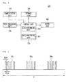
- Fig. 1 is a block diagram of a control device of a high voltage direct current (HVDC) transmission system to which an embodiment is applied
- Fig. 2 illustrates the form of data obtained from the control device of the HVDC transmission system according to an embodiment.
- HVDC high voltage direct current
- a control device 100 of the HVDC transmission system may include a communication unit 110, a data processing unit 120, a storage unit 130, an output unit 140, and a control unit 150.
- the communication unit 110 may receive data on each device connected to the HVDC transmission system.
- the data processing unit 120 may decode data received through the communication unit 110 to output decoded data to the control unit 150. Also, it may encode data analyzed and processed by the control unit 150 after the decoding to output encoded data to a higher application block.
- the storage unit 130 may store data received from the communication unit 110 or store information on how the data has been processed. Also, the storage unit 130 may store data checked by the control unit 150, reference information for checking a line error, and check result information.
- the output unit 140 may data calculated and processed by the data processing unit 120 and the control unit 150 to a valve control unit (not shown) as a valve control value.
- the control unit 150 may monitor the state of data obtained from each controller module connected to the HVDC transmission system obtained through the communication unit 110 and generate valve control data accordingly.
- control unit 150 may include a data monitoring unit 151 and a line monitoring unit 152.
- the data monitoring unit 151 may detect errors of data measured and applied from controllers and check the states of data.
- the data monitoring unit 151 may check the presence and absence of the errors of data based on pulse data including M groups including N signals as shown in Fig. 2 .
- the line monitoring unit 152 may check the reception (receiving rate) of data preset based on the same data as that monitored by the data monitoring unit 151 to check the presence and absence of a line connection.
- the type of data obtained in an embodiment may be M databack groups DMn signals including N pulse signals for a certain period T as shown in Fig. 2 .
- the data obtained from the control device 100 of the HVDC transmission system according to an embodiment may be a pulse signal received for 4 ms (P H ms) at an interval of 4 ms (P L ms) for a period T of 16.67 ms.
- the data input period, section and interval may vary depending on an embodiment.
- Each of the databack signals includes thyristor conduction information, gamma operation information, and break-over diode (BOD) information.
- the control unit 150 may monitor a data error and line connection according to various pieces of information included in the databack signal and depending on the presence and absence of an input of a signal.
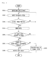
- Fig. 3 is a flow chart for data error verification according to an embodiment.
- control unit 150 for the data error verification is performed at the monitoring unit 151 included in the control unit
- the function may be a portion of the overall operations of the control unit 150.
- the data monitoring unit 151 may be configured in the control unit 150 to be integrated into the control unit 150 or configured in a separate external device.
- control unit 150 may obtain data from control devices connected to the HVDC transmission system and operate in an error monitoring mode in which obtained data is monitored, in step S310.
- the control unit 150 may receive the databack signals DB1 to DBN as shown in Fig. 2 according to the error monitoring mode in step S320.
- the control unit 150 may determine whether a check period for checking the presence and absence of an error and state information on the databack signal has arrived in step S330.
- the check period may correspond to a pulse input period included in the databack signal and is described with e.g., 4 ms in an embodiment.
- the control unit 150 may check the state of data and the presence and absence of error data based on pulse signal data included in the databack signal when the check period of the databack signal has arrived.
- the control unit 150 may check whether error data included in each data in the pulse signal data is output to be high in step S350.
- error data When there is no error in data obtained from a control device, error data may be included and output as a low signal in the pulse signal, and when there is an error in the data, the error data may be included and output as a high signal in a pulse signal of corresponding data.
- control unit 150 may determine whether pulse signal data has error data having a high signal, and when there is error data, it is possible to count the number of error data.
- the control unit 150 may determine whether the number of counted error data or the number of pulse signals of error data represented by high is equal to or larger than a reference number in step S360.
- the reference number may be a level at which error data affects system and valve control. Thus, the reference number is not limited and may vary according to a system or user setting.
- control unit 150 may determine that obtained data is in a normal state and output the data to a valve control device (not shown).
- control unit 150 may determine that the obtained data is error data and output a corresponding result in various forms, in step S380.
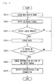
- Fig. 4 is a flow chart for line connection error verification according to an embodiment.
- control unit 150 for the line connection error verification is performed at the line monitoring unit 152 included in the control unit 150
- the function may be a portion of the overall operations of the control unit 150.
- the line monitoring unit 152 may be configured in the control unit 150 to be integrated into the control unit 150 or configured in a separate external device.
- control unit 150 may obtain data from control devices connected to the HVDC transmission system by using physical lines and operate in an error monitoring mode in which obtained data is monitored, in step S410.
- the control unit 150 may receive the databack signals DB1 to DBN as shown in Fig. 2 according to the error monitoring mode, in step S420.
- the control unit 150 may determine whether a check period for checking the presence and absence of an error and state information on the databack signal has arrived in step S430.
- the check period may correspond to a pulse input period included in the databack signal and is described with e.g., 4 ms to be the same as the data check period of the data error verification in an embodiment.
- the control unit 150 may check the presence and absence of no input data based on pulse signal data included in the databack signal when the check period of the databack signal has arrived, in step S440.
- control unit 150 check at the line monitoring unit 152 based on obtained data whether there is a databack signal not received among preset N (22 in an embodiment) databack signals.
- the control unit 150 may check based on the databack signal whether a line signal is input to a line connected physically to control devices and check whether there is on input databack signal, in step S450.
- the control unit 150 may check information on a physical line receiving a signal not input when no input signal among databack signals is checked in step S460.
- the control unit 150 may define that the no input databack signal is an event generated by the error of a physical line connected to a control device, and check information on a line transmitting and receiving the no input signal.
- the control unit 150 may check information on a checked line and the no input signal and output a corresponding error notification in step S470.
- an embodiment describes that the error of a signal line to which a databack signal is not input is checked and a notification is output, it may be processed that a corresponding signal line has an error event when the databack signal is not input a certain number of times or more.
- an embodiment describes check and output operations of a data error and a line error separately based on the databack signal input from control devices, it is possible to perform data error verification and line verification simultaneously at the data monitoring unit 151 and the line monitoring unit 152 of the control unit 150 based on the databack signal.
- Embodiments are mainly described above. However, they are only examples and do not limit the present invention. A person skilled in the art may appreciate that many variations and applications not presented above may be implemented without departing from the essential characteristic of embodiments. For example, each component specifically represented in embodiments may vary.
Landscapes
- Engineering & Computer Science (AREA)
- Power Engineering (AREA)
- Quality & Reliability (AREA)
- Computer Networks & Wireless Communication (AREA)
- Signal Processing (AREA)
- Remote Monitoring And Control Of Power-Distribution Networks (AREA)
- Testing And Monitoring For Control Systems (AREA)
- Direct Current Feeding And Distribution (AREA)
- Selective Calling Equipment (AREA)
- Arrangements For Transmission Of Measured Signals (AREA)
Abstract
Description
- The present disclosure relates to a device and method for controlling a high voltage direct current (HVDC) transmission system.
- HVDC transmission is performed by converting alternating current (AC) power generated from a power station into DC power to transmit the DC power and then re-converting the DC power into the AC power at a power receiving point to supply power. The HVDC transmission may enable efficient and economical power transmission through a voltage increase that is the advantage of AC power transmission. Also, the HVDC transmission may overcome many limitations of the AC transmission.
- A HVDC transmission system may be classified into current-type HVDC using a thyristor and voltage-type HVDC using IGB or GTO. The current-type HVDC is suitable for large power transmission and the voltage-type HVDC is suitable for system stabilization or small power transmission due to high loss.
- In particular, the valve controller of the HVDC transmission system may affect the performance of the entire HVDC transmission system depending on how stably measured data may be maintained and controlled in DC transmission. There is a need for the stability and smooth data flow control of an HVDC transmission system structure.
- In general, data state monitoring consumes a long time to check the cause of an event and to perform corresponding processing while monitoring by software.
- That is, there is a need for a hardware design considering high data reliability and possible events for a state contact of a physical line connected to the HVDC transmission system and a state contact of data. However, since a typical HVDC transmission system is configured to analyze measurement data transmitted to the system and simply distribute analyzed data to a valve control module when the measurement data is transmitted to the system, there is a limitation in that it is not easy to analyze a cause of an event and process the event.
- Embodiments provide a device and method for controlling a high voltage direct current (HVDC) transmission system that enable data validity and a connection state to be checked based on data obtained from the HVDC transmission system.
- Embodiments provide a device and method for controlling a high voltage direct current (HVDC) transmission system that enable the effectiveness of data obtained from the HVDC transmission system and a connection state to be checked so that it is possible to output control data for valve control having high reliability.
- In one embodiment, a device for controlling a high voltage direct current (HVDC) transmission system includes: a communication unit communicating with a control device; a control unit obtaining a databack signal received through the communication unit, checking a data line error and a line connection error based on an obtained databack signal, and outputting a valve control signal based on the databack signal; and an output unit outputting the valve control signal to a valve control device based on control of the control unit.
- In another embodiment, a method of controlling a HVDC transmission system includes: checking a data error and a line connection error depending on presence and absence of an error data output of the databack signal and on presence and absence of an input of the databack signal based on an obtained databack signal; and notifying that the data error or line connection error is sensed.
- The details of one or more embodiments are set forth in the accompanying drawings and the description below. Other features will be apparent from the description and drawings, and from the claims.
-
-
Fig. 1 is a block diagram of a control device of a high voltage direct current (HVDC) transmission system to which an embodiment is applied. -
Fig. 2 illustrates the form of data obtained from the control device of the HVDC transmission system according to an embodiment. -
Fig. 3 is a flow chart for data error verification according to an embodiment. -
Fig. 4 is a flow chart for data error verification according to an embodiment. - The terms or words used in the detailed description and claims should not be limitatively construed as typical meanings or meanings indicated in dictionaries but should be construed as meanings and concepts matching the technical spirit of the present invention based on the principle that the inventor may properly define the concepts of terms in order to describe his or her invention in the best mode.
- Thus, since embodiments described in the detailed description and configurations shown in the drawings are only examples and do not cover all the technical spirits of an embodiment, it should be understood that there may be various equivalents and variations that may replace them upon filing the present application.
-
Fig. 1 is a block diagram of a control device of a high voltage direct current (HVDC) transmission system to which an embodiment is applied, andFig. 2 illustrates the form of data obtained from the control device of the HVDC transmission system according to an embodiment. - Referring to
Figs. 1 and 2 , acontrol device 100 of the HVDC transmission system according to an embodiment may include acommunication unit 110, adata processing unit 120, astorage unit 130, anoutput unit 140, and acontrol unit 150. - The
communication unit 110 may receive data on each device connected to the HVDC transmission system. - The
data processing unit 120 may decode data received through thecommunication unit 110 to output decoded data to thecontrol unit 150. Also, it may encode data analyzed and processed by thecontrol unit 150 after the decoding to output encoded data to a higher application block. - The
storage unit 130 may store data received from thecommunication unit 110 or store information on how the data has been processed. Also, thestorage unit 130 may store data checked by thecontrol unit 150, reference information for checking a line error, and check result information. - The
output unit 140 may data calculated and processed by thedata processing unit 120 and thecontrol unit 150 to a valve control unit (not shown) as a valve control value. - The
control unit 150 may monitor the state of data obtained from each controller module connected to the HVDC transmission system obtained through thecommunication unit 110 and generate valve control data accordingly. - In particular, the
control unit 150 according to an embodiment may include adata monitoring unit 151 and aline monitoring unit 152. - The
data monitoring unit 151 may detect errors of data measured and applied from controllers and check the states of data. Thedata monitoring unit 151 may check the presence and absence of the errors of data based on pulse data including M groups including N signals as shown inFig. 2 . - The
line monitoring unit 152 may check the reception (receiving rate) of data preset based on the same data as that monitored by thedata monitoring unit 151 to check the presence and absence of a line connection. - The type of data obtained in an embodiment may be M databack groups DMn signals including N pulse signals for a certain period T as shown in
Fig. 2 . The data obtained from thecontrol device 100 of the HVDC transmission system according to an embodiment may be a pulse signal received for 4 ms (PHms) at an interval of 4 ms (PLms) for a period T of 16.67 ms. The data input period, section and interval may vary depending on an embodiment. - Each of the databack signals includes thyristor conduction information, gamma operation information, and break-over diode (BOD) information.
- The
control unit 150 may monitor a data error and line connection according to various pieces of information included in the databack signal and depending on the presence and absence of an input of a signal. - In the following, data and line error monitoring operations according to an embodiment are described in detail with reference to
Figs. 3 and4 . -
Fig. 3 is a flow chart for data error verification according to an embodiment. - Although it is described as an example that the
control unit 150 for the data error verification according to an embodiment is performed at themonitoring unit 151 included in the control unit, the function may be a portion of the overall operations of thecontrol unit 150. Thedata monitoring unit 151 may be configured in thecontrol unit 150 to be integrated into thecontrol unit 150 or configured in a separate external device. - Referring to
Fig. 3 , thecontrol unit 150 according to an embodiment may obtain data from control devices connected to the HVDC transmission system and operate in an error monitoring mode in which obtained data is monitored, in step S310. - The
control unit 150 may receive the databack signals DB1 to DBN as shown inFig. 2 according to the error monitoring mode in step S320. - The
control unit 150 may determine whether a check period for checking the presence and absence of an error and state information on the databack signal has arrived in step S330. - The check period may correspond to a pulse input period included in the databack signal and is described with e.g., 4 ms in an embodiment.
- The
control unit 150 may check the state of data and the presence and absence of error data based on pulse signal data included in the databack signal when the check period of the databack signal has arrived. - The
control unit 150 may check whether error data included in each data in the pulse signal data is output to be high in step S350. - When there is no error in data obtained from a control device, error data may be included and output as a low signal in the pulse signal, and when there is an error in the data, the error data may be included and output as a high signal in a pulse signal of corresponding data.
- Thus, the
control unit 150 may determine whether pulse signal data has error data having a high signal, and when there is error data, it is possible to count the number of error data. - The
control unit 150 may determine whether the number of counted error data or the number of pulse signals of error data represented by high is equal to or larger than a reference number in step S360. The reference number may be a level at which error data affects system and valve control. Thus, the reference number is not limited and may vary according to a system or user setting. - When the number of the counted error data is smaller than the reference number, the
control unit 150 may determine that obtained data is in a normal state and output the data to a valve control device (not shown). - On the contrary, when the number of the counted error data is equal to or larger than the reference number, the
control unit 150 may determine that the obtained data is error data and output a corresponding result in various forms, in step S380. -
Fig. 4 is a flow chart for line connection error verification according to an embodiment. - Although it is described as an example that the
control unit 150 for the line connection error verification is performed at theline monitoring unit 152 included in thecontrol unit 150, the function may be a portion of the overall operations of thecontrol unit 150. Theline monitoring unit 152 may be configured in thecontrol unit 150 to be integrated into thecontrol unit 150 or configured in a separate external device. - Referring to
Fig. 4 , thecontrol unit 150 according to an embodiment may obtain data from control devices connected to the HVDC transmission system by using physical lines and operate in an error monitoring mode in which obtained data is monitored, in step S410. - The
control unit 150 may receive the databack signals DB1 to DBN as shown inFig. 2 according to the error monitoring mode, in step S420. - The
control unit 150 may determine whether a check period for checking the presence and absence of an error and state information on the databack signal has arrived in step S430. The check period may correspond to a pulse input period included in the databack signal and is described with e.g., 4 ms to be the same as the data check period of the data error verification in an embodiment. - The
control unit 150 may check the presence and absence of no input data based on pulse signal data included in the databack signal when the check period of the databack signal has arrived, in step S440. - Simultaneously with or separately from the data error verification, the
control unit 150 check at theline monitoring unit 152 based on obtained data whether there is a databack signal not received among preset N (22 in an embodiment) databack signals. - The
control unit 150 may check based on the databack signal whether a line signal is input to a line connected physically to control devices and check whether there is on input databack signal, in step S450. - The
control unit 150 may check information on a physical line receiving a signal not input when no input signal among databack signals is checked in step S460. - The
control unit 150 may define that the no input databack signal is an event generated by the error of a physical line connected to a control device, and check information on a line transmitting and receiving the no input signal. - The
control unit 150 may check information on a checked line and the no input signal and output a corresponding error notification in step S470. - Although an embodiment describes that the error of a signal line to which a databack signal is not input is checked and a notification is output, it may be processed that a corresponding signal line has an error event when the databack signal is not input a certain number of times or more.
- Although an embodiment describes check and output operations of a data error and a line error separately based on the databack signal input from control devices, it is possible to perform data error verification and line verification simultaneously at the
data monitoring unit 151 and theline monitoring unit 152 of thecontrol unit 150 based on the databack signal. - Embodiments are mainly described above. However, they are only examples and do not limit the present invention. A person skilled in the art may appreciate that many variations and applications not presented above may be implemented without departing from the essential characteristic of embodiments. For example, each component specifically represented in embodiments may vary.
- In addition, it should be construed that differences related to such a variation and such an application are included in the scope of the present invention defined in the following claims.
Claims (14)
- A device for controlling a high voltage direct current (HVDC) transmission system, the device comprising:a communication unit communicating with a control device;a control unit obtaining a databack signal received through the communication unit, checking a data line error and a line connection error based on an obtained databack signal, and outputting a valve control signal based on the databack signal; andan output unit outputting the valve control signal to a valve control device based on control of the control unit.
- The device according to claim 1, wherein the databack signal comprises N databack groups comprising M pulse signals.
- The device according to claim 2, wherein the control unit checks the databack signal at a certain interval corresponding to a time when the pulse signal is input.
- The device according to claim 1, wherein the control unit comprises:a data monitoring unit monitoring a data error from the obtained databack signal and extracting error data; anda line monitoring unit monitoring a line connection error from the obtained databack signal and extracting a line connection error.
- The device according to claim 4, wherein the data monitoring unit extracts a signal that error data included in the databack signal is sensed as high, and extracts a databack signal including a corresponding signal as error data.
- The device according to claim 4, wherein the data monitoring unit extracts a corresponding databack signal as error data when a number of signals sensed as high is equal to or larger than a reference number.
- The device according to claim 4, wherein the line monitoring unit checks presence and absence of an input of the databack signal, and identifies a signal line having no databack signal as a line connection.
- The device according to claim 7, wherein the line monitoring unit identifies a corresponding line as a connection when the databack signal is not input a certain number of times or more.
- The device according to claim 1, wherein the control unit checks and extracts presence and absence of a data error and line connection together based on the obtained databack signal.
- A method of controlling a HVDC transmission system, the method comprising:checking a data error and a line connection error depending on presence and absence of an error data output of the databack signal and on presence and absence of an input of the databack signal based on an obtained databack signal; andnotifying that the data error or line connection error is sensed.
- The method according to claim 10, wherein the databack signal comprises N databack groups comprising M pulse signals.
- The method according to claim 11, wherein checking the data error based on the databack signal comprises identifying a corresponding databack signal as a data error when data error signals of the M pulse signals are sensed as high.
- The method according to claim 12, wherein checking the data error comprises identifying as a data error when a number of error signals sensed as high is equal to or larger than a reference number.
- The method according to claim 11, wherein checking the line connection error comprises identifying a line connected to a corresponding databack group as a connection when no input databack group signal among the M data back group signals is sensed.
Applications Claiming Priority (1)
| Application Number | Priority Date | Filing Date | Title |
|---|---|---|---|
| KR1020140008586A KR101562117B1 (en) | 2014-01-23 | 2014-01-23 | Apparatus and method for controlling of High Voltage Direct Current |
Publications (1)
| Publication Number | Publication Date |
|---|---|
| EP2903117A1 true EP2903117A1 (en) | 2015-08-05 |
Family
ID=52449940
Family Applications (1)
| Application Number | Title | Priority Date | Filing Date |
|---|---|---|---|
| EP15151400.7A Pending EP2903117A1 (en) | 2014-01-23 | 2015-01-16 | Device and method for controlling high voltage direct current transmission system |
Country Status (5)
| Country | Link |
|---|---|
| US (1) | US9866027B2 (en) |
| EP (1) | EP2903117A1 (en) |
| JP (1) | JP5918401B2 (en) |
| KR (1) | KR101562117B1 (en) |
| CN (1) | CN104810846B (en) |
Families Citing this family (4)
| Publication number | Priority date | Publication date | Assignee | Title |
|---|---|---|---|---|
| KR101578291B1 (en) * | 2014-05-13 | 2015-12-16 | 엘에스산전 주식회사 | High voltage direct current system |
| CN105158634B (en) * | 2015-09-23 | 2018-04-03 | 中国人民解放军理工大学 | It is a kind of can expanding type signal level lightning protection device broken string, short, intersect short circuit and DC impedance measuring circuit system |
| KR102505454B1 (en) * | 2016-04-28 | 2023-03-03 | 엘에스일렉트릭(주) | Static Var Compensator of controller system and Controlling Method Thereof |
| CN111463899A (en) * | 2020-04-07 | 2020-07-28 | 国家电网有限公司 | A data monitoring device and method for a high-voltage direct current transmission system |
Citations (4)
| Publication number | Priority date | Publication date | Assignee | Title |
|---|---|---|---|---|
| GB2002974A (en) * | 1977-08-19 | 1979-02-28 | Asea Ab | Direct current power transmission system |
| JPS637169A (en) * | 1986-06-25 | 1988-01-13 | Toshiba Corp | Controller for ac/dc converter |
| US6130619A (en) * | 1991-11-21 | 2000-10-10 | Nippondenso Co., Ltd. | Monitoring circuit for a communication device |
| CN101958541A (en) * | 2010-09-10 | 2011-01-26 | 中国电力科学研究院 | Serial coding method for implementing reliable trigger of direct-current power transmission converter valve |
Family Cites Families (13)
| Publication number | Priority date | Publication date | Assignee | Title |
|---|---|---|---|---|
| JPS5568825A (en) | 1978-11-17 | 1980-05-23 | Tokyo Shibaura Electric Co | Dc transmission control protecting device |
| JPS58133122A (en) | 1982-01-29 | 1983-08-08 | 株式会社東芝 | Control system for dc transmission system |
| SE446679B (en) | 1985-02-04 | 1986-09-29 | Asea Ab | PROCEDURE FOR MAINTENANCE OF OPERATION IN A HIGH-SPENDED DC TRANSMISSION IN THE EVENT OF THE TELECOMMUNICATION LINK AND PROTECTION BLOCKING OF ERROR-POWERED DRIVE DRIVER AND EQUIPMENT FOR IMPLEMENTATION OF THE PROCEDURE |
| US4685040A (en) | 1985-12-06 | 1987-08-04 | General Electric Company | Integrated circuit for controlling power converter by frequency modulation and pulse width modulation |
| JPH09322524A (en) | 1996-05-29 | 1997-12-12 | Toshiba Corp | Gate control device for thyristor valve |
| US8098467B2 (en) * | 2005-06-02 | 2012-01-17 | Siemens Aktiengesellschaft | Method for avoidance of inadvertent protective tripping as a result of measurement errors within a protection system for an HVDC transmission installation |
| RU2367083C1 (en) | 2005-09-02 | 2009-09-10 | Сименс Энержди Энд Отомейшн, Инк. | Power delivery system control and diagnoctics |
| US7714587B2 (en) * | 2007-06-29 | 2010-05-11 | Caterpillar Inc. | Systems and methods for detecting a faulty ground strap connection |
| WO2011069548A1 (en) * | 2009-12-10 | 2011-06-16 | Abb Technology Ag | Line fault detector |
| DK2346155T3 (en) | 2010-01-14 | 2014-10-27 | Siemens Ag | Method and control system for controlling power conversion in a power converter |
| JP5520652B2 (en) | 2010-03-26 | 2014-06-11 | 東芝三菱電機産業システム株式会社 | Fault detection circuit for thyristor series circuit |
| US8924033B2 (en) * | 2010-05-12 | 2014-12-30 | Alstom Grid Inc. | Generalized grid security framework |
| US8749933B2 (en) * | 2010-06-14 | 2014-06-10 | Abb Research Ltd | Fault protection of HVDC transmission lines |
-
2014
- 2014-01-23 KR KR1020140008586A patent/KR101562117B1/en active Active
-
2015
- 2015-01-14 US US14/597,057 patent/US9866027B2/en active Active
- 2015-01-16 EP EP15151400.7A patent/EP2903117A1/en active Pending
- 2015-01-22 CN CN201510086170.0A patent/CN104810846B/en active Active
- 2015-01-23 JP JP2015011372A patent/JP5918401B2/en active Active
Patent Citations (4)
| Publication number | Priority date | Publication date | Assignee | Title |
|---|---|---|---|---|
| GB2002974A (en) * | 1977-08-19 | 1979-02-28 | Asea Ab | Direct current power transmission system |
| JPS637169A (en) * | 1986-06-25 | 1988-01-13 | Toshiba Corp | Controller for ac/dc converter |
| US6130619A (en) * | 1991-11-21 | 2000-10-10 | Nippondenso Co., Ltd. | Monitoring circuit for a communication device |
| CN101958541A (en) * | 2010-09-10 | 2011-01-26 | 中国电力科学研究院 | Serial coding method for implementing reliable trigger of direct-current power transmission converter valve |
Also Published As
| Publication number | Publication date |
|---|---|
| KR101562117B1 (en) | 2015-10-22 |
| CN104810846A (en) | 2015-07-29 |
| CN104810846B (en) | 2018-04-27 |
| JP5918401B2 (en) | 2016-05-18 |
| JP2015139369A (en) | 2015-07-30 |
| KR20150088377A (en) | 2015-08-03 |
| US9866027B2 (en) | 2018-01-09 |
| US20150207325A1 (en) | 2015-07-23 |
Similar Documents
| Publication | Publication Date | Title |
|---|---|---|
| EP2903117A1 (en) | Device and method for controlling high voltage direct current transmission system | |
| JP2016099879A5 (en) | ||
| PH12019500944A1 (en) | Cause determination device, power amount management system and cause determination method | |
| KR101735869B1 (en) | Apparatus for Detecting Surge Voltage using Shunt Regulator | |
| US9804575B2 (en) | Multiplex control device | |
| CN104750567A (en) | Watchdog reset method based on FPGA | |
| CN106226708B (en) | Power input detection device | |
| US9401854B2 (en) | System and method for slow link flap detection | |
| CN107340731B (en) | Control device for static var compensator and control method thereof | |
| CN104113871B (en) | A kind of invalid number detecting system and method based on various dimensions | |
| US20150234420A1 (en) | Clock Switching Circuit | |
| US20130103864A1 (en) | Device for indicating status of hard disk | |
| RU159354U1 (en) | DC AND AC DISCRETE SIGNAL DEVICE WITH DIAGNOSTIC OF INSTALLATION OR LOAD OF MONITORED CIRCUIT | |
| CN106502168B (en) | A kind of intelligent power component control system | |
| CN104978002A (en) | Power supply control system and method | |
| US20150039150A1 (en) | Hub and power management method thereof | |
| SG11201807461XA (en) | Information processing device, information processing method, and non-transitory computer readable medium | |
| CN102026254B (en) | Judgment method and device of standing wave alarm and base station | |
| US10574514B2 (en) | Duplex control device and duplex system | |
| CN204359911U (en) | A kind of battery inspection device | |
| JP2015138478A5 (en) | ||
| CN101764664A (en) | PCM signal monitoring device with error detection alarming function and error detection alarming method thereof | |
| CN104217489A (en) | Multi-path magnetic head signal output device, magnetic signal detection equipment and method | |
| US9100142B2 (en) | Synchronous data transmission system | |
| JP6571593B2 (en) | Dual system control system |
Legal Events
| Date | Code | Title | Description |
|---|---|---|---|
| PUAI | Public reference made under article 153(3) epc to a published international application that has entered the european phase |
Free format text: ORIGINAL CODE: 0009012 |
|
| 17P | Request for examination filed |
Effective date: 20150116 |
|
| AK | Designated contracting states |
Kind code of ref document: A1 Designated state(s): AL AT BE BG CH CY CZ DE DK EE ES FI FR GB GR HR HU IE IS IT LI LT LU LV MC MK MT NL NO PL PT RO RS SE SI SK SM TR |
|
| AX | Request for extension of the european patent |
Extension state: BA ME |
|
| 17P | Request for examination filed |
Effective date: 20160203 |
|
| RBV | Designated contracting states (corrected) |
Designated state(s): AL AT BE BG CH CY CZ DE DK EE ES FI FR GB GR HR HU IE IS IT LI LT LU LV MC MK MT NL NO PL PT RO RS SE SI SK SM TR |
|
| STAA | Information on the status of an ep patent application or granted ep patent |
Free format text: STATUS: EXAMINATION IS IN PROGRESS |
|
| 17Q | First examination report despatched |
Effective date: 20191106 |