EP2903065B1 - Method of using a coating device - Google Patents
Method of using a coating device Download PDFInfo
- Publication number
- EP2903065B1 EP2903065B1 EP13841969.2A EP13841969A EP2903065B1 EP 2903065 B1 EP2903065 B1 EP 2903065B1 EP 13841969 A EP13841969 A EP 13841969A EP 2903065 B1 EP2903065 B1 EP 2903065B1
- Authority
- EP
- European Patent Office
- Prior art keywords
- electrolyte membrane
- sheet member
- coating
- base plate
- drawing unit
- Prior art date
- Legal status (The legal status is an assumption and is not a legal conclusion. Google has not performed a legal analysis and makes no representation as to the accuracy of the status listed.)
- Not-in-force
Links
Images


Classifications
-
- H—ELECTRICITY
- H01—ELECTRIC ELEMENTS
- H01M—PROCESSES OR MEANS, e.g. BATTERIES, FOR THE DIRECT CONVERSION OF CHEMICAL ENERGY INTO ELECTRICAL ENERGY
- H01M4/00—Electrodes
- H01M4/86—Inert electrodes with catalytic activity, e.g. for fuel cells
- H01M4/88—Processes of manufacture
- H01M4/8803—Supports for the deposition of the catalytic active composition
- H01M4/881—Electrolytic membranes
-
- B—PERFORMING OPERATIONS; TRANSPORTING
- B05—SPRAYING OR ATOMISING IN GENERAL; APPLYING FLUENT MATERIALS TO SURFACES, IN GENERAL
- B05B—SPRAYING APPARATUS; ATOMISING APPARATUS; NOZZLES
- B05B5/00—Electrostatic spraying apparatus; Spraying apparatus with means for charging the spray electrically; Apparatus for spraying liquids or other fluent materials by other electric means
- B05B5/08—Plant for applying liquids or other fluent materials to objects
- B05B5/14—Plant for applying liquids or other fluent materials to objects specially adapted for coating continuously moving elongated bodies, e.g. wires, strips, pipes
-
- B—PERFORMING OPERATIONS; TRANSPORTING
- B05—SPRAYING OR ATOMISING IN GENERAL; APPLYING FLUENT MATERIALS TO SURFACES, IN GENERAL
- B05B—SPRAYING APPARATUS; ATOMISING APPARATUS; NOZZLES
- B05B13/00—Machines or plants for applying liquids or other fluent materials to surfaces of objects or other work by spraying, not covered by groups B05B1/00 - B05B11/00
- B05B13/02—Means for supporting work; Arrangement or mounting of spray heads; Adaptation or arrangement of means for feeding work
-
- B—PERFORMING OPERATIONS; TRANSPORTING
- B05—SPRAYING OR ATOMISING IN GENERAL; APPLYING FLUENT MATERIALS TO SURFACES, IN GENERAL
- B05C—APPARATUS FOR APPLYING FLUENT MATERIALS TO SURFACES, IN GENERAL
- B05C5/00—Apparatus in which liquid or other fluent material is projected, poured or allowed to flow on to the surface of the work
- B05C5/02—Apparatus in which liquid or other fluent material is projected, poured or allowed to flow on to the surface of the work the liquid or other fluent material being discharged through an outlet orifice by pressure, e.g. from an outlet device in contact or almost in contact, with the work
- B05C5/0283—Flat jet coaters, i.e. apparatus in which the liquid or other fluent material is projected from the outlet as a cohesive flat jet in direction of the work
-
- B—PERFORMING OPERATIONS; TRANSPORTING
- B05—SPRAYING OR ATOMISING IN GENERAL; APPLYING FLUENT MATERIALS TO SURFACES, IN GENERAL
- B05C—APPARATUS FOR APPLYING FLUENT MATERIALS TO SURFACES, IN GENERAL
- B05C13/00—Means for manipulating or holding work, e.g. for separate articles
-
- B—PERFORMING OPERATIONS; TRANSPORTING
- B05—SPRAYING OR ATOMISING IN GENERAL; APPLYING FLUENT MATERIALS TO SURFACES, IN GENERAL
- B05C—APPARATUS FOR APPLYING FLUENT MATERIALS TO SURFACES, IN GENERAL
- B05C5/00—Apparatus in which liquid or other fluent material is projected, poured or allowed to flow on to the surface of the work
- B05C5/02—Apparatus in which liquid or other fluent material is projected, poured or allowed to flow on to the surface of the work the liquid or other fluent material being discharged through an outlet orifice by pressure, e.g. from an outlet device in contact or almost in contact, with the work
-
- B—PERFORMING OPERATIONS; TRANSPORTING
- B05—SPRAYING OR ATOMISING IN GENERAL; APPLYING FLUENT MATERIALS TO SURFACES, IN GENERAL
- B05C—APPARATUS FOR APPLYING FLUENT MATERIALS TO SURFACES, IN GENERAL
- B05C5/00—Apparatus in which liquid or other fluent material is projected, poured or allowed to flow on to the surface of the work
- B05C5/02—Apparatus in which liquid or other fluent material is projected, poured or allowed to flow on to the surface of the work the liquid or other fluent material being discharged through an outlet orifice by pressure, e.g. from an outlet device in contact or almost in contact, with the work
- B05C5/0245—Apparatus in which liquid or other fluent material is projected, poured or allowed to flow on to the surface of the work the liquid or other fluent material being discharged through an outlet orifice by pressure, e.g. from an outlet device in contact or almost in contact, with the work for applying liquid or other fluent material to a moving work of indefinite length, e.g. to a moving web
-
- B—PERFORMING OPERATIONS; TRANSPORTING
- B05—SPRAYING OR ATOMISING IN GENERAL; APPLYING FLUENT MATERIALS TO SURFACES, IN GENERAL
- B05C—APPARATUS FOR APPLYING FLUENT MATERIALS TO SURFACES, IN GENERAL
- B05C5/00—Apparatus in which liquid or other fluent material is projected, poured or allowed to flow on to the surface of the work
- B05C5/02—Apparatus in which liquid or other fluent material is projected, poured or allowed to flow on to the surface of the work the liquid or other fluent material being discharged through an outlet orifice by pressure, e.g. from an outlet device in contact or almost in contact, with the work
- B05C5/0254—Coating heads with slot-shaped outlet
-
- B—PERFORMING OPERATIONS; TRANSPORTING
- B65—CONVEYING; PACKING; STORING; HANDLING THIN OR FILAMENTARY MATERIAL
- B65G—TRANSPORT OR STORAGE DEVICES, e.g. CONVEYORS FOR LOADING OR TIPPING, SHOP CONVEYOR SYSTEMS OR PNEUMATIC TUBE CONVEYORS
- B65G47/00—Article or material-handling devices associated with conveyors; Methods employing such devices
- B65G47/74—Feeding, transfer, or discharging devices of particular kinds or types
- B65G47/90—Devices for picking-up and depositing articles or materials
- B65G47/92—Devices for picking-up and depositing articles or materials incorporating electrostatic or magnetic grippers
-
- B—PERFORMING OPERATIONS; TRANSPORTING
- B65—CONVEYING; PACKING; STORING; HANDLING THIN OR FILAMENTARY MATERIAL
- B65H—HANDLING THIN OR FILAMENTARY MATERIAL, e.g. SHEETS, WEBS, CABLES
- B65H5/00—Feeding articles separated from piles; Feeding articles to machines
- B65H5/004—Feeding articles separated from piles; Feeding articles to machines using electrostatic force
-
- H—ELECTRICITY
- H01—ELECTRIC ELEMENTS
- H01M—PROCESSES OR MEANS, e.g. BATTERIES, FOR THE DIRECT CONVERSION OF CHEMICAL ENERGY INTO ELECTRICAL ENERGY
- H01M8/00—Fuel cells; Manufacture thereof
- H01M8/10—Fuel cells with solid electrolytes
- H01M2008/1095—Fuel cells with polymeric electrolytes
-
- Y—GENERAL TAGGING OF NEW TECHNOLOGICAL DEVELOPMENTS; GENERAL TAGGING OF CROSS-SECTIONAL TECHNOLOGIES SPANNING OVER SEVERAL SECTIONS OF THE IPC; TECHNICAL SUBJECTS COVERED BY FORMER USPC CROSS-REFERENCE ART COLLECTIONS [XRACs] AND DIGESTS
- Y02—TECHNOLOGIES OR APPLICATIONS FOR MITIGATION OR ADAPTATION AGAINST CLIMATE CHANGE
- Y02E—REDUCTION OF GREENHOUSE GAS [GHG] EMISSIONS, RELATED TO ENERGY GENERATION, TRANSMISSION OR DISTRIBUTION
- Y02E60/00—Enabling technologies; Technologies with a potential or indirect contribution to GHG emissions mitigation
- Y02E60/30—Hydrogen technology
- Y02E60/50—Fuel cells
Definitions
- the present invention relates to a method of coating a flexible sheet member according to the preamble of independent claim 1.
- An apparatus for such method can be taken from the prior art document WO 2012/036007 A1 .
- EP 1 857 189 A1 discloses the application of a coating liquid, wherein a coating liquid being supplied is applied on the upper surface of a running web by the use of an application bar, to thereby form a coating film having a desired thickness .
- the coating liquid is directly supplied to a standing liquid being formed in contact with both of the application bar and the web, or the coating liquid is allowed to flow down on a smooth surface in a such a state that its upper side is open to the outside and is supplied for the web.
- Prior art document JP 2006-164790 A discloses a device of forming the catalyst layer for the fuel battery.
- Said device includes a mesh support plate having a holding surface for holding a gas diffusion layer to which a catalyst slurry is applied and having breathability to the direction of a board thickness, and a blower which sucks air from below this mesh support plate by the side of the gas diffusion layer. Drying is made to advance by both sides of the catalyst slurry by flowing air to the front surface and the rear surface of the catalyst slurry.
- a fuel cell is a clean power generation system in which an electrode reaction product is water in principle and which reduces the load on the global environment.
- a polymer electrolyte fuel cell (PEFC) is expected as a power supply for an electric car because it operates at relatively low temperature.
- a polymer fuel cell includes a membrane electrode assembly (MEA, hereinafter referred to as MEA) having an electrolyte membrane, catalyst layers provided on both surfaces of the membrane, gas diffusion layers (GDLs), and so on.
- MEA membrane electrode assembly
- GDLs gas diffusion layers
- a plurality of MEAs are stacked with separators being disposed therebetween to constitute a fuel cell.
- Patent Literature 1 As a technique of forming electrode catalyst layers on both surfaces of an electrolyte membrane when manufacturing an MEA, a method of applying catalyst ink onto the electrolyte membrane is known (see, for example, Patent Literature 1).
- an outer peripheral frame is attached to an electrolyte membrane such as to clamp an outer peripheral portion of the electrolyte membrane.
- a porous sheet is disposed in an aperture of the outer peripheral frame sheet, and catalyst ink is applied while vacuum-sucking the electrolyte membrane via the porous sheet. The porous sheet protects a coating area where the catalyst ink is applied.
- Patent Literature 1 Japanese Unexamined Patent Application Publication No. 2009-129777
- the present invention has been made in view of the above circumstance, and an object of the invention is to provide a method of coating a flexible sheet member that can prevent distortion of the shape of a coating area on a sheet member.
- a coating apparatus for such method includes a base plate on which a flexible sheet member shaped like a thin film is placed, a drawing unit that draws the sheet member onto the base plate, and a coating mechanism that applies a material onto the sheet member drawn on the base plate by the drawing unit.
- the sheet member has, in a range from a center portion to a portion on an inner side of an outer peripheral edge, a coating area where the material is to be applied.
- the drawing unit includes a mechanism configured to electrostatically draw the sheet member, draws the sheet member on the base plate in the coating area where the material is to be applied, and also draws the sheet member on the base plate in a range extending outward beyond the coating area. The range extending outward beyond the coating area is larger than the coating area and smaller than the sheet member.
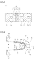
- Fig. 1 is a cross-sectional view illustrating a cell structure of a fuel cell.
- a single cell 10 is applied to, for example, a polymer electrolyte fuel cell (PEFC) using hydrogen as fuel, and includes an MEA 20 and separators 31 and 32.
- PEFC polymer electrolyte fuel cell
- the single cell 10 When the single cell 10 is to be stacked, for example, it further includes a cooling plate 33. Refrigerant channels through which a refrigerant for cooling the single cell 10 flows are formed by grooves 33a provided in the cooling plate 33.
- the MEA 20 includes a polymer electrolyte membrane 21, catalyst layers 22 and 23, and gas diffusion layers (GDLs) 24 and 25.
- GDLs gas diffusion layers
- the catalyst layer 22 contains a catalytic component, a conductive catalyst carrier for carrying the catalytic component, and a polymer electrolyte, serves as an anode catalyst layer in which an oxidation reaction of hydrogen proceeds, and is disposed on one side of the electrolyte membrane 21.
- the catalyst layer 23 contains a catalytic component, a conductive catalyst carrier for carrying the catalytic component, and a polymer electrolyte, serves as a cathode catalyst layer in which a reduction reaction of oxygen proceeds, and is disposed on the other side of the electrolyte membrane 21.
- the electrolyte membrane 21 has the function of selectively allowing protons generated by the catalyst layer 22 to pass therethrough into the catalyst layer 23 and the function as a barrier that prevents mixture of fuel gas supplied to the anode side and oxidant gas supplied to the cathode side.
- the gas diffusion layer 24 is an anode gas diffusion layer that diffuses the fuel gas supplied to the anode side, and is located between the separator 31 and the catalyst layer 22.
- the gas diffusion layer 25 is a cathode gas diffusion layer that diffuses the oxidant gas supplied to the cathode side, and is located between the separator 32 and the catalyst layer 23.
- the separators 31 and 32 have the function of electrically connecting the single cell 10 in series and the function as barriers for isolating the fuel gas, the oxidant gas, and the refrigerant.
- Each of the separators 31 and 32 has almost the same shape as that of the MEA 20, and is formed, for example, by press-working a stainless steel sheet.
- the stainless steel sheet is preferable because of its ease of complicated machining and high conductivity, and can be subjected to corrosive-resistant coating as necessary.
- the separator 31 is an anode separator disposed on the anode side of the MEA 20, is opposed to the catalyst layer 22, and has grooves 31a located between the MEA 20 and the separator 31 to form gas passages.
- the grooves (gas passages) 31a are used to supply fuel gas to the catalyst layer 22.
- the separator 32 is a cathode separator disposed on the cathode side of the MEA 20, is opposed to the catalyst layer 23, and has grooves 32a located between the MEA 20 and the separator 32 to form gas passages.
- the grooves (gas passages) 32a are used to supply oxidant gas to the catalyst layer 23.
- a fluorine-based electrolyte membrane formed of a perfluorocarbon sulfonic acid polymer, a hydrocarbon-based resin membrane containing a sulfonate group, or a porous membrane impregnated with an electrolytic component, such as phosphoric acid or ionic liquid can be applied.
- perfluorocarbon sulfonic acid polymers are Nafion (registered trademark, manufactured by Du Pont Corporation), Aciplex (registered trademark, manufactured by Asahi Kasei Corporation), and Flemion (registered trademark, manufactured by Asahi Glass Co., Ltd.).
- the porous membrane is formed of, for example, polytetrafluoroethylene (PTFE) or polyvinylidene difluoride (PVDF).
- the thickness of the electrolyte membrane 21 is not particularly limited, it is preferably 5 to 300 ⁇ m, and more preferably 10 to 200 ⁇ m from the viewpoints of strength, durability, and output characteristics.
- the catalytic component used in the catalyst layer (cathode catalyst layer) 23 is not particularly limited as long as it catalyzes a reduction reaction of oxygen.
- the catalytic component used in the catalyst layer (anode catalyst layer) 22 is not particularly limited as long as it catalyzes an oxidation reaction of hydrogen.
- a specific catalytic component is selected from, for example, metals such as platinum, ruthenium, iridium, rhodium, palladium, osmium, tungsten, lead, iron, chromium, cobalt, nickel, manganese, vanadium, molybdenum, gallium, and aluminum, and an alloy of these metals.
- the catalytic component preferably contains at least platinum.
- the catalytic component to be applied does not always need to be the same between the cathode catalyst layer and the anode catalyst layer, and can be changed appropriately.
- a main component thereof is preferably carbon particles.
- the carbon particles are formed of carbon black, activated carbon, coke, natural graphite, or artificial graphite.
- the polymer electrolyte used in the catalyst layers 22 and 23 is not particularly limited as long as it has at least high proton conductivity.
- a fluorine-based electrolyte containing fluorine atoms in the entirety or a part of a polymer backbone, or a hydrocarbon-based electrolyte that does not contain fluorine atoms in a polymer backbone is applicable.
- the polymer electrolyte used in the catalyst layers 22 and 23 may be the same as or different from the polymer electrolyte used in the electrolyte membrane 21, it is preferably the same from the viewpoint of enhancement of adhesion of the catalyst layers 22 and 23 to the electrolyte membrane 21.
- the thickness of the catalyst layers is not particularly limited as long as it allows sufficient catalysis of the oxidation reaction of hydrogen (anode side) and the reduction action of oxygen (cathode side), and a thickness similar to the known thickness can be used. Specifically, the thickness of the catalyst layers is preferably 1 to 10 ⁇ m.
- the gas diffusion layers 24 and 25 are formed by using, as a base material, a conductive and porous sheet-shaped material, for example, fabric, paper-like paper-making material, felt, or nonwoven fabric made of carbon such as carbon fiber. While the thickness of the base material is not particularly limited, it is preferably 30 to 500 ⁇ m from the viewpoints of mechanical strength and permeability of gas and water. In the gas diffusion layers 24 and 25, the base material preferably contains a water repellent from the viewpoints of water repellency and suppression of a flooding phenomenon.
- water repellent examples include a fluorine-based polymer material, such as PTFE, PVDF, polyhexafluoropropylene, or a tetrafluoroethylene-hexafluoropropylene copolymer (FEP), polypropylene, and polyethylene.
- fluorine-based polymer material such as PTFE, PVDF, polyhexafluoropropylene, or a tetrafluoroethylene-hexafluoropropylene copolymer (FEP), polypropylene, and polyethylene.
- the material of the separators 31 and 32 is not limited to a stainless steel sheet, and other metal materials (for example, an aluminum plate or a clad material), or carbon, such as dense carbon graphite or a carbon plate, can be applied.
- other metal materials for example, an aluminum plate or a clad material
- carbon such as dense carbon graphite or a carbon plate
- the grooves 31a and 32a can be formed by cutting or screen printing.
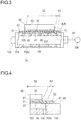
- FIG. 2 is a schematic structural view of a coating apparatus 50 according to an embodiment of the present invention
- Fig. 3 is a cross-sectional view taken along line 3-3 of Fig. 2
- Fig. 4 is an enlarged view of a section 4A in Fig. 3 .
- the coating apparatus 50 includes a base plate 70 on which a flexible sheet member 60 shaped like a thin film is to be placed, a drawing unit 80 that draws the sheet member 60 onto the base plate 70, and a coating mechanism 90 that applies a material 91 onto the sheet member 60 drawn on the base plate 70 by the drawing unit 80.
- the sheet member 60 has a coating area 62, where the material 91 is to be applied, in a range extending from a center portion to portions on inner sides of outer peripheral edges 61.
- the drawing unit 80 draws the sheet member 60 on the base plate 70 in the coating area 62 where the material 91 is applied, and also draws the sheet member 60 on the base plate 70 in a range 63 extending outward beyond the coating area 62 (see Figs. 3 and 4 ).
- the sheet member 60 can be applied to both a one-sided coated sheet member to be coated with the material 91 only on one side, and a double-sided coated sheet member to be coated with the material 91 on both surfaces. That is, the surface of the sheet member 60 to be drawn on the base plate 70 by the drawing unit 80 may be a surface on which the material 91 has not been applied yet or a surface on which the material 91 has already been applied.
- a range 63 extending outward beyond the coating area 62" in which the drawing unit 80 draws the sheet member 60 on the base plate 70 includes the next three ranges.
- the first range is a range that is larger than the coating area 62, but is smaller than the area of the sheet member 60
- the second range is a range that is equal in size to the sheet member 60
- the third range is a range that is larger than the sheet member 60.
- the sheet member 60 is formed of a solvent-impregnated material.
- the solvent-impregnated material is defined as a material whose volume is changed by absorption of solvent. While the solvent is, for example, water or organic solvent, it is not limited thereto.
- the sheet member 60 is an electrolyte membrane 21 formed of a solvent-impregnated material and provided with electrode catalyst layers 22 and 23.
- the material 91 to be applied onto the sheet member 60 is catalyst ink for the electrode catalyst layers 22 and 23.
- the electrolyte membrane 21 is swollen by impregnation with the solvent in the catalyst ink. Swelling of the electrolyte membrane 21 also occurs in the range extending outward beyond the coating area 62.
- the electrolyte membrane 21 is one of the double-sided coated sheet members.
- the electrolyte membrane 21 is long and is wound around a supply reel 101.
- Figs. 2 to 4 illustrate a manner in which catalyst ink 91 for forming one catalyst layer (for example, cathode catalyst layer 23) is applied onto an electrolyte membrane 21 on which the other catalyst layer (for example, anode catalyst layer 22) has already been formed.
- the electrolyte membrane 21 is transported by a roll-to-roll method.
- the electrolyte membrane 21 is paid out from the supply reel 101, and is sequentially wound around a take-up reel 102.
- the coating mechanism 90 is disposed in a transport path through which the electrolyte membrane 21 is transported from the supply reel 101 to the take-up reel 102.
- a suction roller 104 is disposed to be rotatable on a rotation shaft 103.
- the suction roller 104 transports the electrolyte membrane 21 while drawing the electrolyte membrane 21 on its peripheral wall 104a.
- the peripheral wall 104a of the suction roller 104 corresponds to the base plate 70 on which the sheet member 60 is placed.
- the peripheral wall 104a is formed by a porous body such as a punching plate having multiple micropores 105.
- the drawing unit 80 includes a suction mechanism 81 that draws the electrolyte membrane 21 by pressure difference.
- the suction mechanism 81 includes the suction roller 104 having the micropores 105 provided in the peripheral wall 104a and channels 108 for connecting the drawing unit 80 and a suction chamber 107, a vacuum pump 106 that sucks air from the suction chamber 107 provided in the suction roller 104, and so on.
- the suction mechanism 81 sucks air from the suction chamber 107 to form a pressure difference between the inside of the suction roller 104 with negative pressure and the outside of the suction roller 104 with atmospheric pressure. By this pressure difference, the electrolyte membrane 21 is drawn onto the peripheral wall 104a.
- a mechanism for drying the catalyst ink 91 is not particularly limited, a known mechanism can be applied, for example, temperature-increased atmospheric gas is blown onto the electrolyte membrane 21.
- the catalyst ink 91 can also be dried in the transport path before the electrolyte membrane 21 is wound around the take-up reel 102.
- the catalyst ink 91 is preferably dried between the suction roller 104 and the take-up reel 102 while drawing the electrolyte membrane 21 on a base plate by a drawing unit.
- the base plate disposed in the transport path can be formed of a porous body, such as a punching plate having multiple micropores, similarly to the above-described peripheral wall 104a.
- the drawing unit disposed in the transport path can have a suction mechanism for drawing the electrolyte membrane 21 by pressure difference, similarly to the above-described drawing unit 80.
- the suction chamber 107 in the suction roller 104 is divided into a plurality of sections, and vacuum suction and pressure release can be switched in each of the sections .
- the suction chamber 107 continues to draw the electrolyte membrane 21 until the electrolyte membrane 21 separates from the peripheral wall 104a. This is because deformation of the electrolyte membrane 21 during drying can be suppressed by maintaining the drawn state of the electrolyte membrane 21 on the suction roller 104 for as long a time as possible.
- a heater for increasing the temperature of the peripheral wall 104a may be disposed within the suction roller 104, or a heater for increasing the temperature of the applied catalyst ink 91 may be disposed opposed to the suction roller 104.
- a heater for increasing the temperature of the base plate may be disposed within the base plate, or a heater for increasing the temperature of the applied catalyst ink 91 may be disposed opposed to the base plate.
- the coating mechanism 90 includes a coater head 92 disposed opposed to the suction roller 104. To the coater head 92, catalyst ink 91 is supplied from an unillustrated material supply source.
- the coating area 62 where the catalyst ink 91 is to be applied and the range where the electrolyte membrane 21 is to be drawn on the suction roller 104 For convenience of explanation, the direction of the rotation shaft 103 of the suction roller 104 is referred to as the width direction of the electrolyte membrane 21, the width direction of the coating area 62, the width direction of the suction roller 104, and the width direction of an area where the micropores 105 are provided.
- the electrolyte membrane 21 has the coating area 62, where the catalyst ink 91 is to be applied, in a range from the center portion to portions on an inner side of the outer peripheral edges 61. That is, the width of the coating area 62 is smaller than the width of the electrolyte membrane 21.
- An ink discharge port of the coater head 92 has a width equal to the width of the coating area 62.
- the widthwise center of the coater head 92 coincides with the widthwise center of the suction roller 104.
- the electrolyte membrane 21 is drawn and transported by the suction roller 104 with its widthwise center being aligned with the widthwise center of the suction roller 104.
- the widthwise center of the range of the surface of the suction roller 104 where the micropores 105 are provided coincides with the widthwise center of the suction roller 104. Further, the width of the range where the micropores 105 are provided is larger than the width of the coating area 62. Therefore, the drawing unit 80 draws the electrolyte membrane 21 on the peripheral wall 104a in the coating area 62, and also draws the electrolyte membrane 21 on the peripheral wall 104a in the range 63 extending outward beyond the coating area 62.
- the electrolyte membrane 21 is paid out from the supply reel 101, is transported while being drawn on the peripheral wall 104a by pressure difference, and is wound around the take-up reel 102. While the electrolyte membrane 21 is being transported, the catalyst ink 91 is applied onto the electrolyte membrane 21 by the coater head 92.
- the width of the range where the micropores 105 are provided is larger than the width of the coating area 62.
- the drawing unit 80 draws the electrolyte membrane 21 on the peripheral wall 104a in the coating area 62 where the catalyst ink 91 is applied, and also draws the electrolyte membrane 21 on the peripheral wall 104a in the range 63 extending outward beyond the coating area 62.
- the electrolyte membrane 21 is a thin film, even in a state in which the catalyst ink 91 is not applied to any of the surfaces of the electrolyte membrane 21, the electrolyte membrane 21 itself is wrinkled in an outer peripheral portion of the coating area 62, and is wrinkled in the range 63 extending outward beyond the coating area 62.
- the electrolyte membrane 21 formed of the solvent-impregnated material swells while absorbing the solvent in the catalyst ink 91. Since impregnation with the solvent is performed even in the range 63 extending outward beyond the coating area 62, swelling of the electrolyte membrane 21 also occurs in the portion on the ouster side of the coating area 62.
- the range 63 extending outward beyond the coating area 62 also shrinks.
- the electrolyte membrane 21 having one surface coated with the catalyst ink 91 is wrinkled in the outer peripheral portion of the coating area 62 and the range 63 extending outward beyond the coating area 62.
- the shape of an electrode reacting portion of the electrolyte membrane 201 distorts, and dimensional changes occur in widths w1 and w2 and thicknesses t1 and t2 in widthwise end portions of the catalyst layer. Deformation of the electrolyte membrane 201 deteriorates cell performance of the fuel cell.
- the electrolyte membrane 21 is drawn on the peripheral wall 104a in the range 63 extending outward beyond the coating area 62. For this reason, wrinkling in the portion extending outward beyond the coating area 62 can be suppressed, and the distance between the coater head 92 and the electrolyte membrane 21 does not change. In any of the case in which the catalyst ink 91 is applied onto the first surface of the electrolyte membrane 21 and the case in which the catalyst ink 91 is further applied to the second surface of the electrolyte membrane 21 having the first surface to which the catalyst ink 91 has already been applied, wrinkling can be suppressed.
- the cell performance can be prevented from being deteriorated by deformation of the electrolyte membrane.
- Deformation of the electrolyte membrane 21 is suppressed without sticking a backup film to a surface of the electrolyte membrane 21 opposite from the coating surface. Steps of sticking and removing the backup film are unnecessary, and the manufacturing cost is not increased. Further, the problem in that the electrolyte membrane may be broken when the backup film is removed does fundamentally not occur.
- the operations of fixing the outer peripheral edges 61 of the electrolyte membrane 21 to the peripheral wall 104a and unfixing the outer peripheral edges 61 from the peripheral wall 104a are performed only by the drawing unit 80. Therefore, a subsidiary material such as a mask film is unnecessary, and the step of sticking the mask film and the step of removing the mask film are unnecessary. Hence, the increase in cost can be suppressed.
- a broken arrow 64 in Fig. 4 air is sucked from a minute gap between the widthwise end portions of the electrolyte membrane 21 and the peripheral wall 104a, and some air leakage sometimes occurs. Measures against air leakage in this portion may be taken.
- covers to be placed on the widthwise end portions of the electrolyte membrane 21 are attached to the outer periphery of the suction roller 104. When the covers are drawn and placed on the widthwise end portions of the electrolyte membrane 21, air leakage can be reduced.
- the covers have axial cuts provided at predetermined intervals in the circumferential direction. By forming the cuts, the transported electrolyte membrane 21 separates from the peripheral wall 104a without any trouble.
- Vacuum release is performed through the micropores 105 of the suction roller 104 in the center portion of the electrolyte membrane 21, and vacuum release is also performed at the outer peripheral edges 61 of the electrolyte membrane 21. Since vacuum release is thus performed at almost the same time both in the center portion and the outer peripheral edges 61 of the electrolyte membrane 21, stress concentration does not occur in the electrolyte membrane 21, and the occurrence of a crack called a mud crack can be avoided. Further, in a manner in which an electrolyte membrane 21 cut to a predetermined size is drawn on the base plate 70, air leakage occurs at outer peripheral edges 61, and therefore, the electrolyte membrane 21 can be easily picked up in the next step.
- the coating apparatus 50 includes the peripheral wall 104a on which the electrolyte membrane 21 serving as the sheet member 60 is placed, the drawing unit 80, and the coating mechanism 90.
- the drawing unit 80 draws the electrolyte membrane 21 on the peripheral wall 104a in the coating area 62 where the catalyst ink 91 is to be applied, and also draws the electrolyte membrane 21 on the peripheral wall 104a in the range 63 extending outward beyond the coating area 62.
- the material of the sheet member 60 is a solvent-impregnated material.
- the peripheral wall 104a is formed by a porous body, and the drawing unit 80 has the mechanism that draws the electrolyte membrane 21 by pressure difference. In this case, wrinkling in the swelling portion extending outward beyond the coating area 62 can be suppressed by drawing the electrolyte membrane 21 by the pressure difference.
- the surface of the electrolyte membrane 21 to be drawn on the peripheral wall 104a by the drawing unit 80 is a surface to which the catalyst ink 91 has not been applied yet, or a surface to which the catalyst ink 91 has already been applied. According to this structure, wrinkling can be suppressed both when the catalyst ink 91 is applied to the first surface of the electrolyte membrane 21 and when the catalyst ink 91 is further applied to the second surface of the electrolyte membrane 21 with the first surface to which the catalyst ink 91 has been applied. As a result, in any of the cases of one-sided coating and double-sided coating, distortion of the shape of the coating area 62 can be prevented, and the dimensional changes of the catalyst layers 22 and 23 can be reduced.
- the electrolyte membrane 21 has a long shape such as to be paid out from the supply reel 101 and to be sequentially wound around the take-up reel 102.
- the coating mechanism 90 is disposed in the transport path through which the electrolyte membrane 21 is transported from the supply reel 101 to the take-up reel 102. According to this structure, since the electrolyte membrane 21 is transported by the roll-to-roll method, the catalyst layers 22 and 23 can be efficiently formed on the electrolyte membrane 21.
- the applied catalyst ink 91 is dried while the electrolyte membrane 21 is drawn on the peripheral wall 104a by the drawing unit 80.
- deformation of the electrolyte membrane 21 due to drying can be suppressed.
- the dimensional changes of the catalyst layers 22 and 23 can be reduced further.
- the sheet member 60 is the electrolyte membrane 21 on which the electrode catalyst layers 22 and 23 are provided, and the material 91 is the catalyst ink 91 for the electrode catalyst layers. Since deformation of the electrolyte membrane 21 provided with the catalyst layers 22 and 23 can be suppressed, according to the fuel cell to which the electrolyte membrane 21 is applied, the cell performance can be prevented from being deteriorated by deformation of the electrolyte membrane.
- Fig. 6 is a schematic structural view of a coating apparatus 51 according to a second embodiment
- Fig. 7 is a cross-sectional view taken along line 7-7 of Fig. 6 .
- Members common to the first embodiment are denoted by the same reference numerals, and descriptions thereof will be partly omitted.
- the second embodiment is different from the first embodiment, in which the electrolyte membrane 21 is drawn on the base plate 70 by the pressure difference, in that an electrolyte membrane 21 is electrostatically attracted on a base plate 70.
- the coating apparatus 51 of the second embodiment includes a base plate 70 on which an electrolyte membrane 21 is to be placed, a drawing unit 80 that draws the electrolyte membrane 21 on the base plate 70, and a coating mechanism 90 that applies catalyst ink 91 for electrode catalyst layers 22 and 23 onto the electrolyte membrane 21.
- the drawing unit 80 draws the electrolyte membrane 21 on the base plate 70 in a coating area 62 where the catalyst ink 91 is to be applied, and also draws the electrolyte membrane 21 on the base plate 70 in a range 63 extending outward beyond the coating area 62.
- the electrolyte membrane 21 is paid out from a supply reel 111, and is sequentially wound around a take-up reel 112.
- An electrostatic attracting roller 114 rotatable on a rotation shaft 113 is disposed between the supply reel 111 and the take-up reel 112 .
- the electrostatic attracting roller 114 attracts and transports the electrolyte membrane 21 on a peripheral wall 114a.
- the peripheral wall 114a of the electrostatic attracting roller 114 corresponds to a base plate 70 on which a sheet member 60 is to be placed.
- the peripheral wall 114a is formed by an attraction plate 115 in which electrodes for generating electrostatic attracting force are provided.
- the drawing unit 80 includes an attraction mechanism 81 that electrostatically attracts the electrolyte membrane 21.
- the attraction mechanism 81 includes an attraction plate 115 that forms the peripheral wall 114a, a power supply 116 for supplying electric power to the electrodes provided in the attraction plate 115, and so on.
- the attraction mechanism 81 supplies electric power to the electrodes in the attraction plate 115 to generate static electricity in the attraction plate 115. By this static electricity, the electrolyte membrane 21 is attracted on the peripheral wall 114a.
- Applied catalyst ink 91 is dried while the electrolyte membrane 21 is being attracted on the electrostatic attracting roller 114 by the drawing unit 80 utilizing static electricity. This is because deformation of the electrolyte membrane 21 due to drying can be suppressed. While a mechanism for drying the catalyst ink 91 is not particularly limited, a known mechanism can be applied, for example, temperature-increased atmospheric gas is blown onto the electrolyte membrane 21.
- the catalyst ink 91 can also be dried in a transport path through which the electrolyte membrane 21 is transported before being wound around the take-up reel 112, similarly to the first embodiment.
- the catalyst ink 91 is preferably dried between the electrostatic attracting roller 114 and the take-up reel 112 while the electrolyte membrane 21 is being attracted on the base plate by the drawing unit utilizing static electricity.
- a heater for increasing the temperature of the attraction plate 115 in the electrostatic attracting roller 114 is disposed within the electrostatic attracting roller 114, or a heater for increasing the temperature of the applied catalyst ink 91 is disposed opposed to the electrostatic attracting roller 114.
- a heater for increasing the temperature of the base plate may be disposed within the base plate, or a heater for increasing the temperature of the applied catalyst ink 91 may be disposed opposed to the base plate.
- the width of the attraction plate 115 in the electrostatic attracting roller 114 is larger than the width of the coating area 62. Therefore, in the second embodiment, the electrolyte membrane 21 is also attracted on the attraction plate 115 in the coating area 62, and the electrolyte membrane 21 is attracted on the attraction plate 115 in the range 63 extending outward beyond the coating area 62.
- the electrolyte membrane 21 is also attracted on the attraction plate 115 in the range 63 extending outward beyond the coating area 62 when the catalyst ink 91 is applied. For this reason, the portions on the outer sides of the coating area 62 can be restricted from being wrinkled, and the distance between a coater head 92 and the electrolyte membrane 21 does not change. Wrinkling can be suppressed in both when the catalyst ink 91 is applied to a first surface of the electrolyte membrane 21 and when the catalyst ink 91 is further applied to a second surface of the electrolyte membrane 21 having the first surface to which the catalyst ink 91 has already been applied.
- the coating apparatus 51 of the second embodiment includes the peripheral wall 114a on which the electrolyte membrane 21 serving as the sheet member 60 is placed, the drawing unit 80, and the coating mechanism 90.
- the drawing unit 80 draws the electrolyte membrane 21 on the peripheral wall 114a in the coating area 62 where the catalyst ink 91 is to be applied, and also draws the electrolyte membrane 21 on the peripheral wall 114a in the range 63 extending outward beyond the coating area 62.
- the material of the sheet member 60 is the electrolyte membrane 21 formed of a solvent-impregnated material.
- the drawing unit 80 includes the mechanism that electrostatically attracts the electrolyte membrane 21. In this case, since the electrolyte membrane 21 is electrostatically attracted, wrinkling of the swelling portion on the outer side of the coating area 62 can be suppressed.
- the electrolyte membrane 21 provided with the electrode catalyst layers 22 and 23 has been described as the example of the sheet member 60 and the catalyst ink 91 for the electrode catalyst layers has been described as the example of the material 91, the present teaching is not limited to this case.
- the electrolyte membrane 21 formed of the solvent-impregnated material has been described as the example of the sheet member 60, the present teaching is not limited to this case.
- the sheet member 60 can be applied in various forms as long as it is shaped like a flexible thin film, and may be formed of a porous material.
- the material 91 to be applied can be applied in various forms in correspondence with the types of the sheet member 60.
- the present teaching is not limited to this case.
- the range where the sheet member 60 is drawn on the base plate 70 may be a part of the coating area 62 where the material 91 is applied. Further, the drawing force may be partly changed to an extent such as not to wrinkle the sheet member 60 to be drawn.
- the structure of the drawing unit 80 utilizing pressure difference is not limited to this case.
- the sheet member 60 can be drawn on the base plate 70 as long as there is a pressure difference between both spaces between which the base plate 70 is provided. Therefore, the sheet member 60 can also be drawn on the base plate 70 by pressure difference even in a manner in which the pressure in the space, where the sheet member 60 is placed, is increased above the atmospheric pressure and the pressure in the opposite space is released to the atmospheric pressure.
- the method and structure for applying the catalyst ink 91 onto the electrolyte membrane 21 are not particularly limited.
- a known method such as screen printing or a spray method, can be applied similarly.
- the shape and structure of the base plate 70 on which the electrolyte membrane 21 is placed, or the drawing method of the drawing unit 80 can be selected in accordance with the application method for the catalyst ink 91.
Landscapes
- Engineering & Computer Science (AREA)
- Manufacturing & Machinery (AREA)
- Chemical & Material Sciences (AREA)
- Chemical Kinetics & Catalysis (AREA)
- Electrochemistry (AREA)
- General Chemical & Material Sciences (AREA)
- Fuel Cell (AREA)
- Coating Apparatus (AREA)
- Inert Electrodes (AREA)
Description
- The present invention relates to a method of coating a flexible sheet member according to the preamble of independent claim 1. An apparatus for such method can be taken from the prior art document
WO 2012/036007 A1 . -
EP 1 857 189 A1 discloses the application of a coating liquid, wherein a coating liquid being supplied is applied on the upper surface of a running web by the use of an application bar, to thereby form a coating film having a desired thickness . In the upstream side from the application bar, the coating liquid is directly supplied to a standing liquid being formed in contact with both of the application bar and the web, or the coating liquid is allowed to flow down on a smooth surface in a such a state that its upper side is open to the outside and is supplied for the web. - Prior art document
JP 2006-164790 A - In response to recent social demands and trends in the context of energy and environment problems, fuel cells capable of operating even at ordinary temperature and obtaining high output density have attracted attention as a power supply for an electric car and a stationary power supply. A fuel cell is a clean power generation system in which an electrode reaction product is water in principle and which reduces the load on the global environment. In particular, a polymer electrolyte fuel cell (PEFC) is expected as a power supply for an electric car because it operates at relatively low temperature.
- A polymer fuel cell includes a membrane electrode assembly (MEA, hereinafter referred to as MEA) having an electrolyte membrane, catalyst layers provided on both surfaces of the membrane, gas diffusion layers (GDLs), and so on. A plurality of MEAs are stacked with separators being disposed therebetween to constitute a fuel cell.
- As a technique of forming electrode catalyst layers on both surfaces of an electrolyte membrane when manufacturing an MEA, a method of applying catalyst ink onto the electrolyte membrane is known (see, for example, Patent Literature 1). In the method described in Patent Literature 1, an outer peripheral frame is attached to an electrolyte membrane such as to clamp an outer peripheral portion of the electrolyte membrane. A porous sheet is disposed in an aperture of the outer peripheral frame sheet, and catalyst ink is applied while vacuum-sucking the electrolyte membrane via the porous sheet. The porous sheet protects a coating area where the catalyst ink is applied.
- [Patent Literature 1] Japanese Unexamined Patent Application Publication No.
2009-129777 - In the method described in Patent Literature 1, when the electrolyte membrane is vacuum-sucked via the porous sheet, it is drawn in a range on an inner side of an outer peripheral edge portion of the porous sheet, that is, in a range on an inner side of the outer periphery of the coating area.
- For this reason, if a wrinkle occurs in the outer peripheral portion of the electrolyte membrane within the coating area or a wrinkle occurs in a range extending outward beyond the coating area, the distance between a mechanism for applying the catalyst ink and the electrolyte membrane is changed by the influence of the wrinkle. As a result, the shape of an electrode reacting portion of the electrolyte membrane is distorted, and dimensional changes in size and thickness of the applied catalyst occur. Deformation of the electrolyte membrane deteriorates cell performance of a fuel cell to which this electrolyte membrane is applied.
- The present invention has been made in view of the above circumstance, and an object of the invention is to provide a method of coating a flexible sheet member that can prevent distortion of the shape of a coating area on a sheet member.
- According to the present invention said object is solved by a method of coating a flexible sheet member having the features of independent claim 1. Preferred embodiments are laid down in the dependent claims.
- A coating apparatus for such method includes a base plate on which a flexible sheet member shaped like a thin film is placed, a drawing unit that draws the sheet member onto the base plate, and a coating mechanism that applies a material onto the sheet member drawn on the base plate by the drawing unit. The sheet member has, in a range from a center portion to a portion on an inner side of an outer peripheral edge, a coating area where the material is to be applied. The drawing unit includes a mechanism configured to electrostatically draw the sheet member, draws the sheet member on the base plate in the coating area where the material is to be applied, and also draws the sheet member on the base plate in a range extending outward beyond the coating area. The range extending outward beyond the coating area is larger than the coating area and smaller than the sheet member.
-
- [
Fig. 1] Fig. 1 is a cross-sectional view illustrating a cell structure of a fuel cell. - [
Fig. 2] Fig. 2 is a schematic structural view of a coating apparatus according to a first embodiment. - [
Fig. 3] Fig. 3 is a cross-sectional view taken along line 3-3 ofFig. 2 . - [
Fig. 4] Fig. 4 is an enlarged view of asection 4A inFig. 3 . - [
Fig. 5] Figs. 5(A), 5(B), and 5 (C) are explanatory views used to explain trouble that may occur in a comparative example in which an electrolyte membrane is drawn in a range that does not extend outward from a coating area. - [
Fig. 6] Fig. 6 is a schematic structural view of a coating apparatus according to a second embodiment. - [
Fig. 7] Fig. 7 is a cross-sectional view taken along line 7-7 ofFig. 6 . - Embodiments of apparatus for the method of coating of the present invention will be described below with reference to the attached drawings. In the description of the drawings, the same elements are denoted by the same reference numerals, and redundant descriptions thereof are skipped. The dimensional ratios in the drawings are exaggerated for convenience of explanation, and are different from actual ratios.
-
Fig. 1 is a cross-sectional view illustrating a cell structure of a fuel cell. - Referring to
Fig. 1 , asingle cell 10 is applied to, for example, a polymer electrolyte fuel cell (PEFC) using hydrogen as fuel, and includes anMEA 20 andseparators single cell 10 is to be stacked, for example, it further includes acooling plate 33. Refrigerant channels through which a refrigerant for cooling thesingle cell 10 flows are formed bygrooves 33a provided in thecooling plate 33. - The
MEA 20 includes apolymer electrolyte membrane 21,catalyst layers - The
catalyst layer 22 contains a catalytic component, a conductive catalyst carrier for carrying the catalytic component, and a polymer electrolyte, serves as an anode catalyst layer in which an oxidation reaction of hydrogen proceeds, and is disposed on one side of theelectrolyte membrane 21. Thecatalyst layer 23 contains a catalytic component, a conductive catalyst carrier for carrying the catalytic component, and a polymer electrolyte, serves as a cathode catalyst layer in which a reduction reaction of oxygen proceeds, and is disposed on the other side of theelectrolyte membrane 21. - The
electrolyte membrane 21 has the function of selectively allowing protons generated by thecatalyst layer 22 to pass therethrough into thecatalyst layer 23 and the function as a barrier that prevents mixture of fuel gas supplied to the anode side and oxidant gas supplied to the cathode side. - The
gas diffusion layer 24 is an anode gas diffusion layer that diffuses the fuel gas supplied to the anode side, and is located between theseparator 31 and thecatalyst layer 22. Thegas diffusion layer 25 is a cathode gas diffusion layer that diffuses the oxidant gas supplied to the cathode side, and is located between theseparator 32 and thecatalyst layer 23. - The
separators single cell 10 in series and the function as barriers for isolating the fuel gas, the oxidant gas, and the refrigerant. Each of theseparators MEA 20, and is formed, for example, by press-working a stainless steel sheet. The stainless steel sheet is preferable because of its ease of complicated machining and high conductivity, and can be subjected to corrosive-resistant coating as necessary. - The
separator 31 is an anode separator disposed on the anode side of theMEA 20, is opposed to thecatalyst layer 22, and hasgrooves 31a located between theMEA 20 and theseparator 31 to form gas passages. The grooves (gas passages) 31a are used to supply fuel gas to thecatalyst layer 22. - The
separator 32 is a cathode separator disposed on the cathode side of theMEA 20, is opposed to thecatalyst layer 23, and hasgrooves 32a located between theMEA 20 and theseparator 32 to form gas passages. The grooves (gas passages) 32a are used to supply oxidant gas to thecatalyst layer 23. - Next, the materials, sizes, and so on of the constituent members will be described in detail.
- To the
electrolyte membrane 21, a fluorine-based electrolyte membrane formed of a perfluorocarbon sulfonic acid polymer, a hydrocarbon-based resin membrane containing a sulfonate group, or a porous membrane impregnated with an electrolytic component, such as phosphoric acid or ionic liquid, can be applied. Examples of perfluorocarbon sulfonic acid polymers are Nafion (registered trademark, manufactured by Du Pont Corporation), Aciplex (registered trademark, manufactured by Asahi Kasei Corporation), and Flemion (registered trademark, manufactured by Asahi Glass Co., Ltd.). The porous membrane is formed of, for example, polytetrafluoroethylene (PTFE) or polyvinylidene difluoride (PVDF). - While the thickness of the
electrolyte membrane 21 is not particularly limited, it is preferably 5 to 300 µm, and more preferably 10 to 200 µm from the viewpoints of strength, durability, and output characteristics. - The catalytic component used in the catalyst layer (cathode catalyst layer) 23 is not particularly limited as long as it catalyzes a reduction reaction of oxygen. The catalytic component used in the catalyst layer (anode catalyst layer) 22 is not particularly limited as long as it catalyzes an oxidation reaction of hydrogen.
- A specific catalytic component is selected from, for example, metals such as platinum, ruthenium, iridium, rhodium, palladium, osmium, tungsten, lead, iron, chromium, cobalt, nickel, manganese, vanadium, molybdenum, gallium, and aluminum, and an alloy of these metals. To enhance catalytic activity, poisoning resistance to carbon monoxide or the like, heat resistance, etc., the catalytic component preferably contains at least platinum. The catalytic component to be applied does not always need to be the same between the cathode catalyst layer and the anode catalyst layer, and can be changed appropriately.
- While the conductive carrier of the catalyst used in the catalyst layers 22 and 23 is not particularly limited as long as it has a specific surface area such as to carrier the catalytic component in a desired diffused state and a sufficient electronic conductivity as a current collector, a main component thereof is preferably carbon particles. For example, the carbon particles are formed of carbon black, activated carbon, coke, natural graphite, or artificial graphite.
- The polymer electrolyte used in the catalyst layers 22 and 23 is not particularly limited as long as it has at least high proton conductivity. For example, a fluorine-based electrolyte containing fluorine atoms in the entirety or a part of a polymer backbone, or a hydrocarbon-based electrolyte that does not contain fluorine atoms in a polymer backbone is applicable. While the polymer electrolyte used in the catalyst layers 22 and 23 may be the same as or different from the polymer electrolyte used in the
electrolyte membrane 21, it is preferably the same from the viewpoint of enhancement of adhesion of the catalyst layers 22 and 23 to theelectrolyte membrane 21. - The thickness of the catalyst layers is not particularly limited as long as it allows sufficient catalysis of the oxidation reaction of hydrogen (anode side) and the reduction action of oxygen (cathode side), and a thickness similar to the known thickness can be used. Specifically, the thickness of the catalyst layers is preferably 1 to 10 µm.
- The gas diffusion layers 24 and 25 are formed by using, as a base material, a conductive and porous sheet-shaped material, for example, fabric, paper-like paper-making material, felt, or nonwoven fabric made of carbon such as carbon fiber. While the thickness of the base material is not particularly limited, it is preferably 30 to 500 µm from the viewpoints of mechanical strength and permeability of gas and water. In the gas diffusion layers 24 and 25, the base material preferably contains a water repellent from the viewpoints of water repellency and suppression of a flooding phenomenon. Examples of the water repellent are a fluorine-based polymer material, such as PTFE, PVDF, polyhexafluoropropylene, or a tetrafluoroethylene-hexafluoropropylene copolymer (FEP), polypropylene, and polyethylene.
- The material of the
separators grooves - Next, a
coating apparatus 50 will be described with reference toFigs. 2 to 4 .Fig. 2 is a schematic structural view of acoating apparatus 50 according to an embodiment of the present invention,Fig. 3 is a cross-sectional view taken along line 3-3 ofFig. 2 , andFig. 4 is an enlarged view of asection 4A inFig. 3 . - The
coating apparatus 50 will be described briefly. Thecoating apparatus 50 includes abase plate 70 on which aflexible sheet member 60 shaped like a thin film is to be placed, adrawing unit 80 that draws thesheet member 60 onto thebase plate 70, and acoating mechanism 90 that applies a material 91 onto thesheet member 60 drawn on thebase plate 70 by thedrawing unit 80. Thesheet member 60 has acoating area 62, where thematerial 91 is to be applied, in a range extending from a center portion to portions on inner sides of outer peripheral edges 61. Thedrawing unit 80 draws thesheet member 60 on thebase plate 70 in thecoating area 62 where thematerial 91 is applied, and also draws thesheet member 60 on thebase plate 70 in arange 63 extending outward beyond the coating area 62 (seeFigs. 3 and 4 ). Thesheet member 60 can be applied to both a one-sided coated sheet member to be coated with the material 91 only on one side, and a double-sided coated sheet member to be coated with the material 91 on both surfaces. That is, the surface of thesheet member 60 to be drawn on thebase plate 70 by thedrawing unit 80 may be a surface on which thematerial 91 has not been applied yet or a surface on which thematerial 91 has already been applied. - Specifically, "a
range 63 extending outward beyond thecoating area 62" in which thedrawing unit 80 draws thesheet member 60 on thebase plate 70 includes the next three ranges. The first range is a range that is larger than thecoating area 62, but is smaller than the area of thesheet member 60, the second range is a range that is equal in size to thesheet member 60, and the third range is a range that is larger than thesheet member 60. In this embodiment, a manner in which thesheet member 60 is drawn in the first range, which is larger than thecoating area 62 but is smaller than the area of thesheet member 60, will be described as an example. - In the illustrated embodiment, the
sheet member 60 is formed of a solvent-impregnated material. The solvent-impregnated material is defined as a material whose volume is changed by absorption of solvent. While the solvent is, for example, water or organic solvent, it is not limited thereto. - More specifically, the
sheet member 60 is anelectrolyte membrane 21 formed of a solvent-impregnated material and provided with electrode catalyst layers 22 and 23. The material 91 to be applied onto thesheet member 60 is catalyst ink for the electrode catalyst layers 22 and 23. When the catalyst ink is applied, theelectrolyte membrane 21 is swollen by impregnation with the solvent in the catalyst ink. Swelling of theelectrolyte membrane 21 also occurs in the range extending outward beyond thecoating area 62. Theelectrolyte membrane 21 is one of the double-sided coated sheet members. - The
electrolyte membrane 21 is long and is wound around asupply reel 101.Figs. 2 to 4 illustrate a manner in whichcatalyst ink 91 for forming one catalyst layer (for example, cathode catalyst layer 23) is applied onto anelectrolyte membrane 21 on which the other catalyst layer (for example, anode catalyst layer 22) has already been formed. Theelectrolyte membrane 21 is transported by a roll-to-roll method. Theelectrolyte membrane 21 is paid out from thesupply reel 101, and is sequentially wound around a take-upreel 102. Thecoating mechanism 90 is disposed in a transport path through which theelectrolyte membrane 21 is transported from thesupply reel 101 to the take-upreel 102. Between thesupply reel 101 and the take-upreel 102, asuction roller 104 is disposed to be rotatable on arotation shaft 103. Thesuction roller 104 transports theelectrolyte membrane 21 while drawing theelectrolyte membrane 21 on itsperipheral wall 104a. Theperipheral wall 104a of thesuction roller 104 corresponds to thebase plate 70 on which thesheet member 60 is placed. For example, theperipheral wall 104a is formed by a porous body such as a punching plate havingmultiple micropores 105. - The
drawing unit 80 includes asuction mechanism 81 that draws theelectrolyte membrane 21 by pressure difference. In this case, thesuction mechanism 81 includes thesuction roller 104 having themicropores 105 provided in theperipheral wall 104a andchannels 108 for connecting thedrawing unit 80 and asuction chamber 107, avacuum pump 106 that sucks air from thesuction chamber 107 provided in thesuction roller 104, and so on. Thesuction mechanism 81 sucks air from thesuction chamber 107 to form a pressure difference between the inside of thesuction roller 104 with negative pressure and the outside of thesuction roller 104 with atmospheric pressure. By this pressure difference, theelectrolyte membrane 21 is drawn onto theperipheral wall 104a. - It is preferable to dry applied
catalyst ink 91 while drawing theelectrolyte membrane 21 on theperipheral wall 104a of thesuction roller 104 by thedrawing unit 80. This is because deformation of theelectrolyte membrane 21 due to drying can be suppressed. While a mechanism for drying thecatalyst ink 91 is not particularly limited, a known mechanism can be applied, for example, temperature-increased atmospheric gas is blown onto theelectrolyte membrane 21. - The
catalyst ink 91 can also be dried in the transport path before theelectrolyte membrane 21 is wound around the take-upreel 102. In this case, thecatalyst ink 91 is preferably dried between thesuction roller 104 and the take-upreel 102 while drawing theelectrolyte membrane 21 on a base plate by a drawing unit. The base plate disposed in the transport path can be formed of a porous body, such as a punching plate having multiple micropores, similarly to the above-describedperipheral wall 104a. The drawing unit disposed in the transport path can have a suction mechanism for drawing theelectrolyte membrane 21 by pressure difference, similarly to the above-describeddrawing unit 80. - For example, the
suction chamber 107 in thesuction roller 104 is divided into a plurality of sections, and vacuum suction and pressure release can be switched in each of the sections . Thesuction chamber 107 continues to draw theelectrolyte membrane 21 until theelectrolyte membrane 21 separates from theperipheral wall 104a. This is because deformation of theelectrolyte membrane 21 during drying can be suppressed by maintaining the drawn state of theelectrolyte membrane 21 on thesuction roller 104 for as long a time as possible. - To promote drying the applied
catalyst ink 91, a heater for increasing the temperature of theperipheral wall 104a may be disposed within thesuction roller 104, or a heater for increasing the temperature of the appliedcatalyst ink 91 may be disposed opposed to thesuction roller 104. As to the base plate disposed in the transport path, a heater for increasing the temperature of the base plate may be disposed within the base plate, or a heater for increasing the temperature of the appliedcatalyst ink 91 may be disposed opposed to the base plate. - The
coating mechanism 90 includes acoater head 92 disposed opposed to thesuction roller 104. To thecoater head 92,catalyst ink 91 is supplied from an unillustrated material supply source. - With reference to
Figs. 3 and 4 , a description will be given of thecoating area 62 where thecatalyst ink 91 is to be applied and the range where theelectrolyte membrane 21 is to be drawn on thesuction roller 104. For convenience of explanation, the direction of therotation shaft 103 of thesuction roller 104 is referred to as the width direction of theelectrolyte membrane 21, the width direction of thecoating area 62, the width direction of thesuction roller 104, and the width direction of an area where themicropores 105 are provided. - The
electrolyte membrane 21 has thecoating area 62, where thecatalyst ink 91 is to be applied, in a range from the center portion to portions on an inner side of the outer peripheral edges 61. That is, the width of thecoating area 62 is smaller than the width of theelectrolyte membrane 21. An ink discharge port of thecoater head 92 has a width equal to the width of thecoating area 62. The widthwise center of thecoater head 92 coincides with the widthwise center of thesuction roller 104. Theelectrolyte membrane 21 is drawn and transported by thesuction roller 104 with its widthwise center being aligned with the widthwise center of thesuction roller 104. - The widthwise center of the range of the surface of the
suction roller 104 where themicropores 105 are provided coincides with the widthwise center of thesuction roller 104. Further, the width of the range where themicropores 105 are provided is larger than the width of thecoating area 62. Therefore, thedrawing unit 80 draws theelectrolyte membrane 21 on theperipheral wall 104a in thecoating area 62, and also draws theelectrolyte membrane 21 on theperipheral wall 104a in therange 63 extending outward beyond thecoating area 62. - Next, the operation of this embodiment will be described.
- The
electrolyte membrane 21 is paid out from thesupply reel 101, is transported while being drawn on theperipheral wall 104a by pressure difference, and is wound around the take-upreel 102. While theelectrolyte membrane 21 is being transported, thecatalyst ink 91 is applied onto theelectrolyte membrane 21 by thecoater head 92. - The width of the range where the
micropores 105 are provided is larger than the width of thecoating area 62. Thedrawing unit 80 draws theelectrolyte membrane 21 on theperipheral wall 104a in thecoating area 62 where thecatalyst ink 91 is applied, and also draws theelectrolyte membrane 21 on theperipheral wall 104a in therange 63 extending outward beyond thecoating area 62. - Since the
electrolyte membrane 21 is a thin film, even in a state in which thecatalyst ink 91 is not applied to any of the surfaces of theelectrolyte membrane 21, theelectrolyte membrane 21 itself is wrinkled in an outer peripheral portion of thecoating area 62, and is wrinkled in therange 63 extending outward beyond thecoating area 62. Theelectrolyte membrane 21 formed of the solvent-impregnated material swells while absorbing the solvent in thecatalyst ink 91. Since impregnation with the solvent is performed even in therange 63 extending outward beyond thecoating area 62, swelling of theelectrolyte membrane 21 also occurs in the portion on the ouster side of thecoating area 62. When the appliedcatalyst ink 91 dries, therange 63 extending outward beyond thecoating area 62 also shrinks. As a result, theelectrolyte membrane 21 having one surface coated with thecatalyst ink 91 is wrinkled in the outer peripheral portion of thecoating area 62 and therange 63 extending outward beyond thecoating area 62. - When an
electrolyte membrane 201 is drawn on aperipheral wall 203a of asuction roller 203 in a range that does not extend outward beyond acoating area 202, as in a comparative example illustrated inFig. 5 , the following problem occurs. When appliedcatalyst ink 204 dries, aportion 205 extending outward beyond thecoating area 202 also shrinks, and wrinkles prominently appear in theportion 205 extending outward beyond thecoating area 202 of theelectrolyte membrane 201. By the influence of the wrinkles, the distance between acoater head 206 and theelectrolyte membrane 201 is changed. As a result, the shape of an electrode reacting portion of theelectrolyte membrane 201 distorts, and dimensional changes occur in widths w1 and w2 and thicknesses t1 and t2 in widthwise end portions of the catalyst layer. Deformation of theelectrolyte membrane 201 deteriorates cell performance of the fuel cell. - In contrast, in the first embodiment, when the
catalyst ink 91 is applied, theelectrolyte membrane 21 is drawn on theperipheral wall 104a in therange 63 extending outward beyond thecoating area 62. For this reason, wrinkling in the portion extending outward beyond thecoating area 62 can be suppressed, and the distance between thecoater head 92 and theelectrolyte membrane 21 does not change. In any of the case in which thecatalyst ink 91 is applied onto the first surface of theelectrolyte membrane 21 and the case in which thecatalyst ink 91 is further applied to the second surface of theelectrolyte membrane 21 having the first surface to which thecatalyst ink 91 has already been applied, wrinkling can be suppressed. As a result, distortion of the shape of thecoating area 62 of theelectrolyte membrane 21 can be prevented, and the dimensional changes do not occur to the width and the thickness of the widthwise end portions of the catalyst layer. Hence, according to the fuel cell to which theelectrolyte membrane 21 is applied, the cell performance can be prevented from being deteriorated by deformation of the electrolyte membrane. - Deformation of the
electrolyte membrane 21 is suppressed without sticking a backup film to a surface of theelectrolyte membrane 21 opposite from the coating surface. Steps of sticking and removing the backup film are unnecessary, and the manufacturing cost is not increased. Further, the problem in that the electrolyte membrane may be broken when the backup film is removed does fundamentally not occur. - It is conceivable to suppress deformation of the electrolyte membrane by clamping the electrolyte membrane by a mask film having an aperture and to apply the catalyst ink after that. However, a mask film serving as a subsidiary material to be disposed of after use is necessary, and a step of forming the aperture in the mask film, a step of sticking the mask film to the electrolyte membrane, a step of removing the mask film from the electrolyte membrane, and so on are necessary. As a result, the manufacturing cost becomes relatively high.
- In contrast to this, in the embodiment, the operations of fixing the outer
peripheral edges 61 of theelectrolyte membrane 21 to theperipheral wall 104a and unfixing the outerperipheral edges 61 from theperipheral wall 104a are performed only by thedrawing unit 80. Therefore, a subsidiary material such as a mask film is unnecessary, and the step of sticking the mask film and the step of removing the mask film are unnecessary. Hence, the increase in cost can be suppressed. - In this case, as shown by a
broken arrow 64 inFig. 4 , air is sucked from a minute gap between the widthwise end portions of theelectrolyte membrane 21 and theperipheral wall 104a, and some air leakage sometimes occurs. Measures against air leakage in this portion may be taken. For example, covers to be placed on the widthwise end portions of theelectrolyte membrane 21 are attached to the outer periphery of thesuction roller 104. When the covers are drawn and placed on the widthwise end portions of theelectrolyte membrane 21, air leakage can be reduced. The covers have axial cuts provided at predetermined intervals in the circumferential direction. By forming the cuts, the transportedelectrolyte membrane 21 separates from theperipheral wall 104a without any trouble. - Conversely to the above, measures against air leakage at the outer
peripheral edges 61 of theelectrolyte membrane 21 can be omitted. This case has the following merits. When vacuum suction is stopped, air leakage occurs at the outerperipheral edges 61 of theelectrolyte membrane 21. Hence, release from the vacuum suction state (vacuum release) is easy, and vacuum release is not performed through theelectrolyte membrane 21. Since the time necessary for the vacuum release is shortened, quick transition to the next step can be achieved, and this can enhance mass productivity. It is unnecessary to add a valve for vacuum release, and equipment cost is not increased. Vacuum release is performed through themicropores 105 of thesuction roller 104 in the center portion of theelectrolyte membrane 21, and vacuum release is also performed at the outerperipheral edges 61 of theelectrolyte membrane 21. Since vacuum release is thus performed at almost the same time both in the center portion and the outerperipheral edges 61 of theelectrolyte membrane 21, stress concentration does not occur in theelectrolyte membrane 21, and the occurrence of a crack called a mud crack can be avoided. Further, in a manner in which anelectrolyte membrane 21 cut to a predetermined size is drawn on thebase plate 70, air leakage occurs at outerperipheral edges 61, and therefore, theelectrolyte membrane 21 can be easily picked up in the next step. - As described above, the
coating apparatus 50 according to the first embodiment includes theperipheral wall 104a on which theelectrolyte membrane 21 serving as thesheet member 60 is placed, thedrawing unit 80, and thecoating mechanism 90. Thedrawing unit 80 draws theelectrolyte membrane 21 on theperipheral wall 104a in thecoating area 62 where thecatalyst ink 91 is to be applied, and also draws theelectrolyte membrane 21 on theperipheral wall 104a in therange 63 extending outward beyond thecoating area 62. For this reason, wrinkling in the outer peripheral portion of thecoating area 62 of theelectrolyte membrane 21 and wrinkling in therange 63 extending outward beyond thecoating area 62 can be suppressed, and the distance between thecoater head 92 of thecoating mechanism 90 and theelectrolyte membrane 21 is not changed by the influence of wrinkling. As a result, distortion of the shape of thecoating area 62 of theelectrolyte membrane 21 can be prevented, and the dimensional changes in the width and the thickness of the widthwise end portions of the catalyst layers 22 and 23 can be suppressed. - For example, the material of the
sheet member 60 is a solvent-impregnated material. Theperipheral wall 104a is formed by a porous body, and thedrawing unit 80 has the mechanism that draws theelectrolyte membrane 21 by pressure difference. In this case, wrinkling in the swelling portion extending outward beyond thecoating area 62 can be suppressed by drawing theelectrolyte membrane 21 by the pressure difference. - The surface of the
electrolyte membrane 21 to be drawn on theperipheral wall 104a by thedrawing unit 80 is a surface to which thecatalyst ink 91 has not been applied yet, or a surface to which thecatalyst ink 91 has already been applied. According to this structure, wrinkling can be suppressed both when thecatalyst ink 91 is applied to the first surface of theelectrolyte membrane 21 and when thecatalyst ink 91 is further applied to the second surface of theelectrolyte membrane 21 with the first surface to which thecatalyst ink 91 has been applied. As a result, in any of the cases of one-sided coating and double-sided coating, distortion of the shape of thecoating area 62 can be prevented, and the dimensional changes of the catalyst layers 22 and 23 can be reduced. - The
electrolyte membrane 21 has a long shape such as to be paid out from thesupply reel 101 and to be sequentially wound around the take-upreel 102. Thecoating mechanism 90 is disposed in the transport path through which theelectrolyte membrane 21 is transported from thesupply reel 101 to the take-upreel 102. According to this structure, since theelectrolyte membrane 21 is transported by the roll-to-roll method, the catalyst layers 22 and 23 can be efficiently formed on theelectrolyte membrane 21. - The applied
catalyst ink 91 is dried while theelectrolyte membrane 21 is drawn on theperipheral wall 104a by thedrawing unit 80. Thus, deformation of theelectrolyte membrane 21 due to drying can be suppressed. As a result, the dimensional changes of the catalyst layers 22 and 23 can be reduced further. - The
sheet member 60 is theelectrolyte membrane 21 on which the electrode catalyst layers 22 and 23 are provided, and thematerial 91 is thecatalyst ink 91 for the electrode catalyst layers. Since deformation of theelectrolyte membrane 21 provided with the catalyst layers 22 and 23 can be suppressed, according to the fuel cell to which theelectrolyte membrane 21 is applied, the cell performance can be prevented from being deteriorated by deformation of the electrolyte membrane. -
Fig. 6 is a schematic structural view of acoating apparatus 51 according to a second embodiment, andFig. 7 is a cross-sectional view taken along line 7-7 ofFig. 6 . Members common to the first embodiment are denoted by the same reference numerals, and descriptions thereof will be partly omitted. - The second embodiment is different from the first embodiment, in which the
electrolyte membrane 21 is drawn on thebase plate 70 by the pressure difference, in that anelectrolyte membrane 21 is electrostatically attracted on abase plate 70. - Similarly to the
coating apparatus 50 of the first embodiment, thecoating apparatus 51 of the second embodiment includes abase plate 70 on which anelectrolyte membrane 21 is to be placed, adrawing unit 80 that draws theelectrolyte membrane 21 on thebase plate 70, and acoating mechanism 90 that appliescatalyst ink 91 for electrode catalyst layers 22 and 23 onto theelectrolyte membrane 21. Thedrawing unit 80 draws theelectrolyte membrane 21 on thebase plate 70 in acoating area 62 where thecatalyst ink 91 is to be applied, and also draws theelectrolyte membrane 21 on thebase plate 70 in arange 63 extending outward beyond thecoating area 62. - The
electrolyte membrane 21 is paid out from asupply reel 111, and is sequentially wound around a take-upreel 112. An electrostatic attractingroller 114 rotatable on arotation shaft 113 is disposed between thesupply reel 111 and the take-upreel 112 . The electrostatic attractingroller 114 attracts and transports theelectrolyte membrane 21 on aperipheral wall 114a. Theperipheral wall 114a of the electrostatic attractingroller 114 corresponds to abase plate 70 on which asheet member 60 is to be placed. For example, theperipheral wall 114a is formed by anattraction plate 115 in which electrodes for generating electrostatic attracting force are provided. - The
drawing unit 80 includes anattraction mechanism 81 that electrostatically attracts theelectrolyte membrane 21. In this case, theattraction mechanism 81 includes anattraction plate 115 that forms theperipheral wall 114a, apower supply 116 for supplying electric power to the electrodes provided in theattraction plate 115, and so on. Theattraction mechanism 81 supplies electric power to the electrodes in theattraction plate 115 to generate static electricity in theattraction plate 115. By this static electricity, theelectrolyte membrane 21 is attracted on theperipheral wall 114a. -
Applied catalyst ink 91 is dried while theelectrolyte membrane 21 is being attracted on the electrostatic attractingroller 114 by thedrawing unit 80 utilizing static electricity. This is because deformation of theelectrolyte membrane 21 due to drying can be suppressed. While a mechanism for drying thecatalyst ink 91 is not particularly limited, a known mechanism can be applied, for example, temperature-increased atmospheric gas is blown onto theelectrolyte membrane 21. - The
catalyst ink 91 can also be dried in a transport path through which theelectrolyte membrane 21 is transported before being wound around the take-upreel 112, similarly to the first embodiment. In this case, thecatalyst ink 91 is preferably dried between the electrostatic attractingroller 114 and the take-upreel 112 while theelectrolyte membrane 21 is being attracted on the base plate by the drawing unit utilizing static electricity. - To dry the applied
catalyst ink 91, a heater for increasing the temperature of theattraction plate 115 in the electrostatic attractingroller 114 is disposed within the electrostatic attractingroller 114, or a heater for increasing the temperature of the appliedcatalyst ink 91 is disposed opposed to the electrostatic attractingroller 114. As to the base plate disposed in the transport path, a heater for increasing the temperature of the base plate may be disposed within the base plate, or a heater for increasing the temperature of the appliedcatalyst ink 91 may be disposed opposed to the base plate. - As illustrated in
Fig. 7 , the width of theattraction plate 115 in the electrostatic attractingroller 114 is larger than the width of thecoating area 62. Therefore, in the second embodiment, theelectrolyte membrane 21 is also attracted on theattraction plate 115 in thecoating area 62, and theelectrolyte membrane 21 is attracted on theattraction plate 115 in therange 63 extending outward beyond thecoating area 62. - In the second embodiment, the
electrolyte membrane 21 is also attracted on theattraction plate 115 in therange 63 extending outward beyond thecoating area 62 when thecatalyst ink 91 is applied. For this reason, the portions on the outer sides of thecoating area 62 can be restricted from being wrinkled, and the distance between acoater head 92 and theelectrolyte membrane 21 does not change. Wrinkling can be suppressed in both when thecatalyst ink 91 is applied to a first surface of theelectrolyte membrane 21 and when thecatalyst ink 91 is further applied to a second surface of theelectrolyte membrane 21 having the first surface to which thecatalyst ink 91 has already been applied. As a result, distortion of the shape of thecoating area 62 of theelectrolyte membrane 21 can be prevented, and the dimensional changes in the width and the thickness in the widthwise end portions of the catalyst layers do not occur. Hence, according to a fuel cell to which theelectrolyte membrane 21 is applied, cell performance can be prevented from being deteriorated by deformation of theelectrolyte membrane 21. - As described above, the
coating apparatus 51 of the second embodiment includes theperipheral wall 114a on which theelectrolyte membrane 21 serving as thesheet member 60 is placed, thedrawing unit 80, and thecoating mechanism 90. Thedrawing unit 80 draws theelectrolyte membrane 21 on theperipheral wall 114a in thecoating area 62 where thecatalyst ink 91 is to be applied, and also draws theelectrolyte membrane 21 on theperipheral wall 114a in therange 63 extending outward beyond thecoating area 62. For this reason, wrinkling in the outer peripheral portions of thecoating area 62 of theelectrolyte membrane 21 and wrinkling in therange 63 extending outward beyond thecoating area 62 can be suppressed, and the distance between thecoater head 92 of thecoating mechanism 90 and theelectrolyte membrane 21 is not changed by the influence of wrinkling. As a result, distortion of the shape of thecoating area 62 of theelectrolyte membrane 21 can be prevented, and the dimensional changes in the width and the thickness of the widthwise end portions of the catalyst layers 22 and 23 can be reduced. - For example, the material of the
sheet member 60 is theelectrolyte membrane 21 formed of a solvent-impregnated material. Thedrawing unit 80 includes the mechanism that electrostatically attracts theelectrolyte membrane 21. In this case, since theelectrolyte membrane 21 is electrostatically attracted, wrinkling of the swelling portion on the outer side of thecoating area 62 can be suppressed. - Moreover, while the
electrolyte membrane 21 provided with the electrode catalyst layers 22 and 23 has been described as the example of thesheet member 60 and thecatalyst ink 91 for the electrode catalyst layers has been described as the example of thematerial 91, the present teaching is not limited to this case. Further, while theelectrolyte membrane 21 formed of the solvent-impregnated material has been described as the example of thesheet member 60, the present teaching is not limited to this case. Thesheet member 60 can be applied in various forms as long as it is shaped like a flexible thin film, and may be formed of a porous material. The material 91 to be applied can be applied in various forms in correspondence with the types of thesheet member 60. - While the manner in which the
drawing unit 80 draws almost theentire coating area 62, to which thecatalyst ink 91 is applied, on thebase plate 70 has been described, the present teaching is not limited to this case. The range where thesheet member 60 is drawn on thebase plate 70 may be a part of thecoating area 62 where thematerial 91 is applied. Further, the drawing force may be partly changed to an extent such as not to wrinkle thesheet member 60 to be drawn. - While the space opposite from the space in which the
sheet member 60 is placed, of both spaces between which thebase plate 70 is provided, has negative pressure in the first embodiment, the structure of thedrawing unit 80 utilizing pressure difference is not limited to this case. Thesheet member 60 can be drawn on thebase plate 70 as long as there is a pressure difference between both spaces between which thebase plate 70 is provided. Therefore, thesheet member 60 can also be drawn on thebase plate 70 by pressure difference even in a manner in which the pressure in the space, where thesheet member 60 is placed, is increased above the atmospheric pressure and the pressure in the opposite space is released to the atmospheric pressure. - While the manner in which the
catalyst ink 91 is applied by thecoater head 92 has been described, the method and structure for applying thecatalyst ink 91 onto theelectrolyte membrane 21 are not particularly limited. For example, a known method, such as screen printing or a spray method, can be applied similarly. The shape and structure of thebase plate 70 on which theelectrolyte membrane 21 is placed, or the drawing method of thedrawing unit 80 can be selected in accordance with the application method for thecatalyst ink 91. -
- 10 Single cell
- 20 Membrane electrode assembly (MEA)
- 21 Electrolyte membrane
- 22, 23 Catalyst layer
- 24, 25 Gas diffusion layer
- 31, 32 Separator
- 50, 51 Coating apparatus
- 60 Sheet member
- 61 Outer peripheral edge
- 62 Coating area
- 63 Range extending outward beyond coating area
- 70 Base plate
- 80 Drawing unit
- 81 Suction mechanism
- 90 Coating mechanism
- 91 Catalyst ink (material)
- 92 Coater head
- 101 Supply reel
- 102 Take-up reel
- 103 Rotation shaft
- 104 Suction roller
- 104a Peripheral wall of suction roller (base plate)
- 105 Micropore
- 106 Vacuum pump
- 107 Suction chamber
- 108 Channel
- 111 Supply reel
- 112 Take-up reel
- 113 Rotation shaft
- 114 Electrostatic attracting roller
- 114a Peripheral wall of electrostatic attracting roller (base plate)
- 115 Attraction plate
- 116 Power supply
Claims (6)
- A method of coating a flexible sheet member (60), the method comprising:
a coating apparatus having:a base plate (70, 114a) configured to place the flexible sheet member (60) shaped like a thin film;a drawing unit (80) configured to draw the sheet member (60) onto the base plate (70, 114a), wherein the drawing unit (80) includes a mechanism (81) configured to electrostatically draw the sheet member (60); anda coating mechanism (90), characterized in thatthe coating mechanism (90) is configured to apply a material (91) onto the sheet member (60) at a coating area (62) in a range which is smaller than an area where the sheet member (60) is drawn on the base plate (70, 114a) by the drawing unit (80), and whereinthe drawing unit (80) is configured to draw the sheet member (60) on the base plate (70, 114a) in a range which is smaller than an area of the sheet member (60). - A method of coating according to Claim 1, characterized in that the sheet member (60) is formed of a porous material or a solvent-impregnated material.
- A method of coating according to Claim 1 or 2, characterized in that a surface of the sheet member (60) drawn on the base plate (70, 114a) by the drawing unit (80) is a surface to which the material (91) has not been applied yet or a surface to which the material (91) has already been applied.
- A method of coating according to any one of Claims 1 to 3, characterized in that the sheet member (60) has a long shape such as to be paid out from a supply reel (111) and to be sequentially wound around a take-up reel (112), and
wherein the coating mechanism (90) is disposed in a transport path through which the sheet member (60) is transported from the supply reel (111) to the take-up reel (112). - A method of coating according to any one of Claims 1 to 4, characterized in that the applied material (91) is dried while the sheet member (60) is drawn on the base plate (70, 114a) by the drawing unit (80).
- A method of coating according to any one of Claims 1 to 5, characterized in that the sheet member (60) is an electrolyte membrane (21) having an electrode catalyst layer (22, 23), and
wherein the material (91) is catalyst ink for the electrode catalyst layer.
Applications Claiming Priority (2)
| Application Number | Priority Date | Filing Date | Title |
|---|---|---|---|
| JP2012217075 | 2012-09-28 | ||
| PCT/JP2013/072819 WO2014050406A1 (en) | 2012-09-28 | 2013-08-27 | Coating device |
Publications (3)
| Publication Number | Publication Date |
|---|---|
| EP2903065A1 EP2903065A1 (en) | 2015-08-05 |
| EP2903065A4 EP2903065A4 (en) | 2015-12-23 |
| EP2903065B1 true EP2903065B1 (en) | 2018-07-18 |
Family
ID=50387815
Family Applications (1)
| Application Number | Title | Priority Date | Filing Date |
|---|---|---|---|
| EP13841969.2A Not-in-force EP2903065B1 (en) | 2012-09-28 | 2013-08-27 | Method of using a coating device |
Country Status (6)
| Country | Link |
|---|---|
| US (1) | US9486821B2 (en) |
| EP (1) | EP2903065B1 (en) |
| JP (1) | JP5920479B2 (en) |
| CN (1) | CN104685683A (en) |
| CA (1) | CA2886571C (en) |
| WO (1) | WO2014050406A1 (en) |
Families Citing this family (13)
| Publication number | Priority date | Publication date | Assignee | Title |
|---|---|---|---|---|
| JP2015216066A (en) * | 2014-05-13 | 2015-12-03 | 本田技研工業株式会社 | Manufacturing method of electrolyte membrane / electrode structure for fuel cell |
| JP6428536B2 (en) * | 2014-08-29 | 2018-11-28 | 日産自動車株式会社 | Manufacturing apparatus for sheet material on which coating film is formed, and method for manufacturing sheet material on which coating film is formed |
| KR101575312B1 (en) * | 2014-10-21 | 2015-12-07 | 현대자동차 주식회사 | Device for manufacturing membrane-electrode assembly of fuel cell |
| JP6541531B2 (en) * | 2015-09-28 | 2019-07-10 | 株式会社Screenホールディングス | Apparatus and method for manufacturing membrane / catalyst layer assembly |
| JP6817746B2 (en) * | 2016-08-19 | 2021-01-20 | 株式会社Screenホールディングス | Adsorption roller, coating equipment and membrane / electrode assembly manufacturing equipment |
| CN107716213B (en) * | 2017-10-17 | 2019-04-23 | 安徽电信器材贸易工业有限责任公司 | A kind of cable carbon black applying device |
| RU183384U1 (en) * | 2017-11-13 | 2018-09-19 | Федеральное государственное бюджетное учреждение науки Институт катализа им. Г.К. Борескова Сибирского отделения Российской академии наук | Link-flip device for organizing refueling paintings |
| CN108630871B (en) * | 2018-05-16 | 2021-05-28 | 深圳市星源材质科技股份有限公司 | Battery, battery diaphragm and preparation method thereof |
| CN108480135A (en) * | 2018-05-24 | 2018-09-04 | 陈鸿奇 | A kind of apparatus for coating of coiled film base material coating |
| KR20220009991A (en) * | 2019-05-16 | 2022-01-25 | 드래곤플라이 에너지 코퍼레이션 | Systems and methods for dry powder coating layers of an electrochemical cell |
| US10857632B1 (en) * | 2019-05-24 | 2020-12-08 | Trusval Technology Co., Ltd. | Method for manufacturing high-efficiency protective paper having functions of heat dissipation, heat conduction and electromagnetic absorption |
| WO2023121313A1 (en) * | 2021-12-22 | 2023-06-29 | 주식회사 엘지에너지솔루션 | Drying device and drying method for electrode sheet |
| DE102024201266A1 (en) | 2024-02-12 | 2025-08-14 | Robert Bosch Gesellschaft mit beschränkter Haftung | Method and device for producing a membrane unit for an electrochemical energy converter |
Family Cites Families (15)
| Publication number | Priority date | Publication date | Assignee | Title |
|---|---|---|---|---|
| US3206323A (en) * | 1962-06-12 | 1965-09-14 | Eastman Kodak Co | Coating high viscosity liquids |
| US5003325A (en) * | 1990-01-22 | 1991-03-26 | Rastergraphics, Inc. | Electric field paper stabilizing system for an electrographic plotter, printer or the like |
| US6171658B1 (en) * | 1998-02-06 | 2001-01-09 | Eastman Kodak Company | Coating method using electrostatic assist |
| CN1268016C (en) * | 2001-03-07 | 2006-08-02 | 松下电器产业株式会社 | polymer electrolyte fuel cell |
| JP2002270189A (en) * | 2001-03-07 | 2002-09-20 | Matsushita Electric Ind Co Ltd | Method for manufacturing polymer electrolyte fuel cell and polymer electrolyte fuel cell using the same |
| JP2005205268A (en) | 2004-01-21 | 2005-08-04 | Hitachi Industries Co Ltd | Coating apparatus and coating method |
| JP2006164790A (en) * | 2004-12-08 | 2006-06-22 | Nissan Motor Co Ltd | Apparatus for forming catalyst layer for fuel cell and method for forming catalyst layer for fuel cell |
| US8733275B2 (en) * | 2005-03-11 | 2014-05-27 | Toray Industries, Inc. | Application apparatus, application method and method for manufacturing web having coating film |
| JP2007250539A (en) * | 2006-02-20 | 2007-09-27 | Nissan Motor Co Ltd | Catalyst coating method and catalyst coating apparatus |
| JP5055815B2 (en) * | 2006-04-14 | 2012-10-24 | 日産自動車株式会社 | Method for forming catalyst layer for electrode of fuel cell and catalyst layer for electrode |
| JP4908958B2 (en) * | 2006-07-21 | 2012-04-04 | 本田技研工業株式会社 | Manufacturing method and apparatus for electrolyte / electrode assembly |
| JP2009129777A (en) | 2007-11-26 | 2009-06-11 | Toyota Motor Corp | Manufacturing method of membrane electrode assembly for fuel cell |
| JP2009238511A (en) * | 2008-03-26 | 2009-10-15 | Toyota Motor Corp | Method for manufacturing membrane electrode assembly and its manufacturing device |
| JP5365326B2 (en) * | 2009-04-22 | 2013-12-11 | トヨタ自動車株式会社 | Manufacturing method of membrane electrode assembly for fuel cell |
| JP5831454B2 (en) * | 2010-09-13 | 2015-12-09 | 凸版印刷株式会社 | Membrane electrode assembly, method for manufacturing membrane electrode assembly, and fuel cell |
-
2013
- 2013-08-27 CA CA2886571A patent/CA2886571C/en active Active
- 2013-08-27 WO PCT/JP2013/072819 patent/WO2014050406A1/en not_active Ceased
- 2013-08-27 JP JP2014538294A patent/JP5920479B2/en not_active Expired - Fee Related
- 2013-08-27 EP EP13841969.2A patent/EP2903065B1/en not_active Not-in-force
- 2013-08-27 CN CN201380050293.8A patent/CN104685683A/en active Pending
- 2013-08-27 US US14/431,434 patent/US9486821B2/en not_active Expired - Fee Related
Non-Patent Citations (1)
| Title |
|---|
| None * |
Also Published As
| Publication number | Publication date |
|---|---|
| WO2014050406A1 (en) | 2014-04-03 |
| US20150217308A1 (en) | 2015-08-06 |
| EP2903065A1 (en) | 2015-08-05 |
| CA2886571A1 (en) | 2014-04-03 |
| CA2886571C (en) | 2016-06-07 |
| US9486821B2 (en) | 2016-11-08 |
| JP5920479B2 (en) | 2016-05-25 |
| EP2903065A4 (en) | 2015-12-23 |
| CN104685683A (en) | 2015-06-03 |
| JPWO2014050406A1 (en) | 2016-08-22 |
Similar Documents
| Publication | Publication Date | Title |
|---|---|---|
| CA2886571C (en) | Coating apparatus | |
| US9331345B2 (en) | Bonded sheet and sheet-member bonding method | |
| JP7811560B2 (en) | Membrane Seal Assembly | |
| CN104428933B (en) | Holding device for electrolyte membrane for fuel cell | |
| EP3147977B1 (en) | Apparatus for and method of manufacturing catalyst-coated membrane | |
| JP2003178780A (en) | Polymer electrolyte fuel cell system and method of operating polymer electrolyte fuel cell | |
| JP4940575B2 (en) | ELECTROLYTE MEMBRANE-ELECTRODE ASSEMBLY WITH MASK FILM FOR SOLID POLYMER FUEL CELL AND METHOD FOR PRODUCING THE SAME | |
| JP5178968B2 (en) | POLYMER ELECTROLYTE FUEL CELL AND MANUFACTURING METHOD THEREOF | |
| JP5880710B2 (en) | Gasket for fuel cell gasket | |
| JP2006338939A (en) | Electrolyte membrane-electrode assembly | |
| KR102110843B1 (en) | Process | |
| JP2006338943A (en) | Electrolyte membrane-electrode assembly | |
| JP5273207B2 (en) | ELECTROLYTE MEMBRANE-ELECTRODE ASSEMBLY WITH MASK FILM FOR SOLID POLYMER FUEL CELL AND METHOD FOR PRODUCING THE SAME | |
| JP7307109B2 (en) | Membrane electrode assembly with gas diffusion layer and manufacturing method thereof | |
| JP4852894B2 (en) | Method for producing electrolyte membrane-electrode assembly | |
| JP2013084427A (en) | Method for manufacturing membrane-catalyst layer assembly and method for manufacturing membrane electrode assembly | |
| JP6356436B2 (en) | Electrolyte membrane / electrode structure | |
| JP2010257669A (en) | Membrane electrode assembly, method for producing the same, and polymer electrolyte fuel cell | |
| JP2013004390A (en) | Method of manufacturing assembly of electrolytic membrane and catalyst layer for fuel cell | |
| JP2007335163A (en) | Membrane catalyst layer assembly, membrane electrode assembly, and polymer electrolyte fuel cell | |
| US20220271314A1 (en) | Fuel cell | |
| JP2018163745A (en) | MEMBRANE ELECTRODE ASSEMBLY FOR FUEL CELL AND METHOD FOR MANUFACTURING THE SAME | |
| JP2013084426A (en) | Method for manufacturing membrane-catalyst layer assembly and method for manufacturing membrane electrode assembly | |
| WO2023153454A1 (en) | Membrane electrode assembly and solid polymer fuel cell | |
| JP2007335162A (en) | Membrane catalyst layer assembly, membrane electrode assembly, and polymer electrolyte fuel cell |
Legal Events
| Date | Code | Title | Description |
|---|---|---|---|
| PUAI | Public reference made under article 153(3) epc to a published international application that has entered the european phase |
Free format text: ORIGINAL CODE: 0009012 |
|
| 17P | Request for examination filed |
Effective date: 20150326 |
|
| AK | Designated contracting states |
Kind code of ref document: A1 Designated state(s): AL AT BE BG CH CY CZ DE DK EE ES FI FR GB GR HR HU IE IS IT LI LT LU LV MC MK MT NL NO PL PT RO RS SE SI SK SM TR |
|
| AX | Request for extension of the european patent |
Extension state: BA ME |
|
| RA4 | Supplementary search report drawn up and despatched (corrected) |
Effective date: 20151119 |
|
| RIC1 | Information provided on ipc code assigned before grant |
Ipc: H01M 8/10 20060101ALI20151113BHEP Ipc: B05C 13/00 20060101ALN20151113BHEP Ipc: B05C 13/02 20060101ALI20151113BHEP Ipc: H01M 4/88 20060101AFI20151113BHEP Ipc: B05B 5/14 20060101ALI20151113BHEP Ipc: B05C 5/02 20060101ALN20151113BHEP Ipc: B05C 9/14 20060101ALI20151113BHEP |
|
| DAX | Request for extension of the european patent (deleted) | ||
| RIC1 | Information provided on ipc code assigned before grant |
Ipc: H01M 4/88 20060101ALI20160809BHEP Ipc: B65H 5/00 20060101ALN20160809BHEP Ipc: B05C 9/14 20060101ALI20160809BHEP Ipc: H01M 8/1018 20160101ALN20160809BHEP Ipc: B05B 13/02 20060101AFI20160809BHEP Ipc: B05C 5/02 20060101ALN20160809BHEP Ipc: B05C 13/00 20060101ALN20160809BHEP Ipc: B65G 47/92 20060101ALN20160809BHEP |
|
| 17Q | First examination report despatched |
Effective date: 20160901 |
|
| GRAP | Despatch of communication of intention to grant a patent |
Free format text: ORIGINAL CODE: EPIDOSNIGR1 |
|
| RIC1 | Information provided on ipc code assigned before grant |
Ipc: B05C 13/00 20060101ALN20180323BHEP Ipc: H01M 4/88 20060101AFI20180323BHEP Ipc: B65G 47/92 20060101ALN20180323BHEP Ipc: B65H 5/00 20060101ALN20180323BHEP Ipc: B05C 5/02 20060101ALN20180323BHEP Ipc: H01M 8/1018 20160101ALN20180323BHEP |
|
| INTG | Intention to grant announced |
Effective date: 20180411 |
|
| GRAS | Grant fee paid |
Free format text: ORIGINAL CODE: EPIDOSNIGR3 |
|
| GRAA | (expected) grant |
Free format text: ORIGINAL CODE: 0009210 |
|
| AK | Designated contracting states |
Kind code of ref document: B1 Designated state(s): AL AT BE BG CH CY CZ DE DK EE ES FI FR GB GR HR HU IE IS IT LI LT LU LV MC MK MT NL NO PL PT RO RS SE SI SK SM TR |
|
| REG | Reference to a national code |
Ref country code: GB Ref legal event code: FG4D |
|
| REG | Reference to a national code |
Ref country code: CH Ref legal event code: EP |
|
| REG | Reference to a national code |
Ref country code: IE Ref legal event code: FG4D |
|
| REG | Reference to a national code |
Ref country code: AT Ref legal event code: REF Ref document number: 1020321 Country of ref document: AT Kind code of ref document: T Effective date: 20180815 |
|
| REG | Reference to a national code |
Ref country code: DE Ref legal event code: R096 Ref document number: 602013040600 Country of ref document: DE |
|
| REG | Reference to a national code |
Ref country code: FR Ref legal event code: PLFP Year of fee payment: 6 |
|
| REG | Reference to a national code |
Ref country code: NL Ref legal event code: MP Effective date: 20180718 |
|
| REG | Reference to a national code |
Ref country code: LT Ref legal event code: MG4D |
|
| REG | Reference to a national code |
Ref country code: AT Ref legal event code: MK05 Ref document number: 1020321 Country of ref document: AT Kind code of ref document: T Effective date: 20180718 |
|
| PG25 | Lapsed in a contracting state [announced via postgrant information from national office to epo] |
Ref country code: NL Free format text: LAPSE BECAUSE OF FAILURE TO SUBMIT A TRANSLATION OF THE DESCRIPTION OR TO PAY THE FEE WITHIN THE PRESCRIBED TIME-LIMIT Effective date: 20180718 |
|
| PG25 | Lapsed in a contracting state [announced via postgrant information from national office to epo] |
Ref country code: LT Free format text: LAPSE BECAUSE OF FAILURE TO SUBMIT A TRANSLATION OF THE DESCRIPTION OR TO PAY THE FEE WITHIN THE PRESCRIBED TIME-LIMIT Effective date: 20180718 Ref country code: PL Free format text: LAPSE BECAUSE OF FAILURE TO SUBMIT A TRANSLATION OF THE DESCRIPTION OR TO PAY THE FEE WITHIN THE PRESCRIBED TIME-LIMIT Effective date: 20180718 Ref country code: IS Free format text: LAPSE BECAUSE OF FAILURE TO SUBMIT A TRANSLATION OF THE DESCRIPTION OR TO PAY THE FEE WITHIN THE PRESCRIBED TIME-LIMIT Effective date: 20181118 Ref country code: AT Free format text: LAPSE BECAUSE OF FAILURE TO SUBMIT A TRANSLATION OF THE DESCRIPTION OR TO PAY THE FEE WITHIN THE PRESCRIBED TIME-LIMIT Effective date: 20180718 Ref country code: BG Free format text: LAPSE BECAUSE OF FAILURE TO SUBMIT A TRANSLATION OF THE DESCRIPTION OR TO PAY THE FEE WITHIN THE PRESCRIBED TIME-LIMIT Effective date: 20181018 Ref country code: GR Free format text: LAPSE BECAUSE OF FAILURE TO SUBMIT A TRANSLATION OF THE DESCRIPTION OR TO PAY THE FEE WITHIN THE PRESCRIBED TIME-LIMIT Effective date: 20181019 Ref country code: NO Free format text: LAPSE BECAUSE OF FAILURE TO SUBMIT A TRANSLATION OF THE DESCRIPTION OR TO PAY THE FEE WITHIN THE PRESCRIBED TIME-LIMIT Effective date: 20181018 Ref country code: SE Free format text: LAPSE BECAUSE OF FAILURE TO SUBMIT A TRANSLATION OF THE DESCRIPTION OR TO PAY THE FEE WITHIN THE PRESCRIBED TIME-LIMIT Effective date: 20180718 Ref country code: FI Free format text: LAPSE BECAUSE OF FAILURE TO SUBMIT A TRANSLATION OF THE DESCRIPTION OR TO PAY THE FEE WITHIN THE PRESCRIBED TIME-LIMIT Effective date: 20180718 Ref country code: RS Free format text: LAPSE BECAUSE OF FAILURE TO SUBMIT A TRANSLATION OF THE DESCRIPTION OR TO PAY THE FEE WITHIN THE PRESCRIBED TIME-LIMIT Effective date: 20180718 |
|
| PG25 | Lapsed in a contracting state [announced via postgrant information from national office to epo] |
Ref country code: HR Free format text: LAPSE BECAUSE OF FAILURE TO SUBMIT A TRANSLATION OF THE DESCRIPTION OR TO PAY THE FEE WITHIN THE PRESCRIBED TIME-LIMIT Effective date: 20180718 Ref country code: AL Free format text: LAPSE BECAUSE OF FAILURE TO SUBMIT A TRANSLATION OF THE DESCRIPTION OR TO PAY THE FEE WITHIN THE PRESCRIBED TIME-LIMIT Effective date: 20180718 Ref country code: LV Free format text: LAPSE BECAUSE OF FAILURE TO SUBMIT A TRANSLATION OF THE DESCRIPTION OR TO PAY THE FEE WITHIN THE PRESCRIBED TIME-LIMIT Effective date: 20180718 |
|
| REG | Reference to a national code |
Ref country code: CH Ref legal event code: PL |
|
| REG | Reference to a national code |
Ref country code: DE Ref legal event code: R097 Ref document number: 602013040600 Country of ref document: DE |
|
| PG25 | Lapsed in a contracting state [announced via postgrant information from national office to epo] |
Ref country code: IT Free format text: LAPSE BECAUSE OF FAILURE TO SUBMIT A TRANSLATION OF THE DESCRIPTION OR TO PAY THE FEE WITHIN THE PRESCRIBED TIME-LIMIT Effective date: 20180718 Ref country code: RO Free format text: LAPSE BECAUSE OF FAILURE TO SUBMIT A TRANSLATION OF THE DESCRIPTION OR TO PAY THE FEE WITHIN THE PRESCRIBED TIME-LIMIT Effective date: 20180718 Ref country code: CZ Free format text: LAPSE BECAUSE OF FAILURE TO SUBMIT A TRANSLATION OF THE DESCRIPTION OR TO PAY THE FEE WITHIN THE PRESCRIBED TIME-LIMIT Effective date: 20180718 Ref country code: CH Free format text: LAPSE BECAUSE OF NON-PAYMENT OF DUE FEES Effective date: 20180831 Ref country code: EE Free format text: LAPSE BECAUSE OF FAILURE TO SUBMIT A TRANSLATION OF THE DESCRIPTION OR TO PAY THE FEE WITHIN THE PRESCRIBED TIME-LIMIT Effective date: 20180718 Ref country code: LI Free format text: LAPSE BECAUSE OF NON-PAYMENT OF DUE FEES Effective date: 20180831 Ref country code: MC Free format text: LAPSE BECAUSE OF FAILURE TO SUBMIT A TRANSLATION OF THE DESCRIPTION OR TO PAY THE FEE WITHIN THE PRESCRIBED TIME-LIMIT Effective date: 20180718 Ref country code: ES Free format text: LAPSE BECAUSE OF FAILURE TO SUBMIT A TRANSLATION OF THE DESCRIPTION OR TO PAY THE FEE WITHIN THE PRESCRIBED TIME-LIMIT Effective date: 20180718 Ref country code: LU Free format text: LAPSE BECAUSE OF NON-PAYMENT OF DUE FEES Effective date: 20180827 |
|
| REG | Reference to a national code |
Ref country code: BE Ref legal event code: MM Effective date: 20180831 |
|
| PLBE | No opposition filed within time limit |
Free format text: ORIGINAL CODE: 0009261 |
|
| STAA | Information on the status of an ep patent application or granted ep patent |
Free format text: STATUS: NO OPPOSITION FILED WITHIN TIME LIMIT |
|
| PG25 | Lapsed in a contracting state [announced via postgrant information from national office to epo] |
Ref country code: SM Free format text: LAPSE BECAUSE OF FAILURE TO SUBMIT A TRANSLATION OF THE DESCRIPTION OR TO PAY THE FEE WITHIN THE PRESCRIBED TIME-LIMIT Effective date: 20180718 Ref country code: SK Free format text: LAPSE BECAUSE OF FAILURE TO SUBMIT A TRANSLATION OF THE DESCRIPTION OR TO PAY THE FEE WITHIN THE PRESCRIBED TIME-LIMIT Effective date: 20180718 Ref country code: DK Free format text: LAPSE BECAUSE OF FAILURE TO SUBMIT A TRANSLATION OF THE DESCRIPTION OR TO PAY THE FEE WITHIN THE PRESCRIBED TIME-LIMIT Effective date: 20180718 |
|
| 26N | No opposition filed |
Effective date: 20190423 |
|
| PG25 | Lapsed in a contracting state [announced via postgrant information from national office to epo] |
Ref country code: SI Free format text: LAPSE BECAUSE OF FAILURE TO SUBMIT A TRANSLATION OF THE DESCRIPTION OR TO PAY THE FEE WITHIN THE PRESCRIBED TIME-LIMIT Effective date: 20180718 Ref country code: BE Free format text: LAPSE BECAUSE OF NON-PAYMENT OF DUE FEES Effective date: 20180831 |
|
| PG25 | Lapsed in a contracting state [announced via postgrant information from national office to epo] |
Ref country code: MT Free format text: LAPSE BECAUSE OF NON-PAYMENT OF DUE FEES Effective date: 20180827 |
|
| PG25 | Lapsed in a contracting state [announced via postgrant information from national office to epo] |
Ref country code: TR Free format text: LAPSE BECAUSE OF FAILURE TO SUBMIT A TRANSLATION OF THE DESCRIPTION OR TO PAY THE FEE WITHIN THE PRESCRIBED TIME-LIMIT Effective date: 20180718 |
|
| PG25 | Lapsed in a contracting state [announced via postgrant information from national office to epo] |
Ref country code: PT Free format text: LAPSE BECAUSE OF FAILURE TO SUBMIT A TRANSLATION OF THE DESCRIPTION OR TO PAY THE FEE WITHIN THE PRESCRIBED TIME-LIMIT Effective date: 20180718 |
|
| PG25 | Lapsed in a contracting state [announced via postgrant information from national office to epo] |
Ref country code: HU Free format text: LAPSE BECAUSE OF FAILURE TO SUBMIT A TRANSLATION OF THE DESCRIPTION OR TO PAY THE FEE WITHIN THE PRESCRIBED TIME-LIMIT; INVALID AB INITIO Effective date: 20130827 Ref country code: IE Free format text: LAPSE BECAUSE OF NON-PAYMENT OF DUE FEES Effective date: 20180827 Ref country code: MK Free format text: LAPSE BECAUSE OF NON-PAYMENT OF DUE FEES Effective date: 20180718 Ref country code: CY Free format text: LAPSE BECAUSE OF FAILURE TO SUBMIT A TRANSLATION OF THE DESCRIPTION OR TO PAY THE FEE WITHIN THE PRESCRIBED TIME-LIMIT Effective date: 20180718 |
|
| PGFP | Annual fee paid to national office [announced via postgrant information from national office to epo] |
Ref country code: GB Payment date: 20220707 Year of fee payment: 10 Ref country code: DE Payment date: 20220608 Year of fee payment: 10 |
|
| PGFP | Annual fee paid to national office [announced via postgrant information from national office to epo] |
Ref country code: FR Payment date: 20220709 Year of fee payment: 10 |
|
| REG | Reference to a national code |
Ref country code: DE Ref legal event code: R119 Ref document number: 602013040600 Country of ref document: DE |
|
| GBPC | Gb: european patent ceased through non-payment of renewal fee |
Effective date: 20230827 |
|
| PG25 | Lapsed in a contracting state [announced via postgrant information from national office to epo] |
Ref country code: GB Free format text: LAPSE BECAUSE OF NON-PAYMENT OF DUE FEES Effective date: 20230827 |
|
| PG25 | Lapsed in a contracting state [announced via postgrant information from national office to epo] |
Ref country code: GB Free format text: LAPSE BECAUSE OF NON-PAYMENT OF DUE FEES Effective date: 20230827 Ref country code: FR Free format text: LAPSE BECAUSE OF NON-PAYMENT OF DUE FEES Effective date: 20230831 Ref country code: DE Free format text: LAPSE BECAUSE OF NON-PAYMENT OF DUE FEES Effective date: 20240301 |