EP2902973B1 - Verfahren und Vorrichtung zur Verarbeitung eines Geometriebildes einer 3D-Szene - Google Patents
Verfahren und Vorrichtung zur Verarbeitung eines Geometriebildes einer 3D-Szene Download PDFInfo
- Publication number
- EP2902973B1 EP2902973B1 EP14305145.6A EP14305145A EP2902973B1 EP 2902973 B1 EP2902973 B1 EP 2902973B1 EP 14305145 A EP14305145 A EP 14305145A EP 2902973 B1 EP2902973 B1 EP 2902973B1
- Authority
- EP
- European Patent Office
- Prior art keywords
- pixel
- chart
- border
- pixels
- mesh coordinates
- Prior art date
- Legal status (The legal status is an assumption and is not a legal conclusion. Google has not performed a legal analysis and makes no representation as to the accuracy of the status listed.)
- Active
Links
Images


Classifications
-
- G—PHYSICS
- G06—COMPUTING OR CALCULATING; COUNTING
- G06T—IMAGE DATA PROCESSING OR GENERATION, IN GENERAL
- G06T17/00—Three-dimensional [3D] modelling for computer graphics
- G06T17/20—Finite element generation, e.g. wire-frame surface description, tesselation
-
- G—PHYSICS
- G06—COMPUTING OR CALCULATING; COUNTING
- G06T—IMAGE DATA PROCESSING OR GENERATION, IN GENERAL
- G06T15/00—Three-dimensional [3D] image rendering
- G06T15/005—General purpose rendering architectures
Definitions
- the present disclosure relates to the domain of processing one or more geometry images of a 3D scene and to the reconstruction of a 3D scene from the associated geometry image.
- the present disclosure is also understood in the context of Computer Generated Image (CGI or 3D-CGI), geometry processing and modelling.
- CGI Computer Generated Image
- each chart of the geometry image is independent from its neighbors. This representation does not allow jumping from a chart to another at run-time. For instance, being on border pixel of a source chart of the geometry image, there is no solution to find its neighbor in a destination chart. While geometry images are good mesh data structure for fast GPU access, it is impossible to use such representation to arbitrarily move around the object because charts are always independent.
- multi-chart geometry images discloses a new representation for arbitrary surfaces by means of multi-chart geometry images, created by resampling a surface into a 2D grid.
- the article “Connectivity-preserving Geometry Images” by Wang, S., et al published on December 2013 on the Internet at http://www.researchgate.net/publication/259528490 _Connectivity-preserving_Geometry_Images discusses a method for reconstructing a mesh without sampling error.
- the purpose of the present disclosure is to overcome at least one of these disadvantages of the background art. More specifically, the purpose of the present disclosure is to link charts of a geometry image with each others.
- the present disclosure relates to a method of processing a geometry image, the geometry image being generated from a mesh associated with a 3D scene, the geometry image comprising a first chart and at least a second chart, each first and second chart representing a part of the 3D scene.
- the method comprises the following steps, for at least one current pixel of the first chart different from pixels of the first chart forming border of the first chart:
- pixels of the neighbourhood of the first pixel used to compute candidate directions belong to the border of the first chart.
- pixels of the neighbourhood of the first pixel used to compute candidate directions are outside the boundary of the first chart and adjacent to the selected pixel.
- the pixel of the border of the at least a second chart which corresponds to the pixel of the neighbourhood of the first pixel is determined by comparing the mesh coordinates of the pixel of the neighbourhood of the first pixel with mesh coordinates of a plurality of pixels of the border of the at least a second chart, the determined pixel of the border of the at least a second chart being the pixel for which the difference between its mesh coordinates and the mesh coordinates of the pixel of the neighbourhood of the first pixel is minimal.
- the selected pixel corresponds to the pixel for which the difference between the reference direction and the candidate direction associated to the selected pixel is minimal with regard to the differences between the reference direction and the other candidate directions.
- the method further comprises determining a direction for scanning the at least a second chart corresponding to the determined direction, the direction being determined according to the determined direction, a tangent to the border of the first chart at the first pixel and a tangent to the border of the at least a second chart at the selected pixel.
- the present disclosure also relates to a device configured for processing a geometry image, the geometry image being generated from a mesh associated with a 3D scene, the geometry image comprising a first chart and at least a second chart, each first and second chart representing a part of the 3D scene, the device comprising at least one processor configured for, for at least one current pixel of the first chart different from pixels of the first chart forming border of the first chart:
- the at least one processor is further configured for comparing the mesh coordinates of the pixel of the neighbourhood of the first pixel with mesh coordinates of a plurality of pixels of the border of the at least a second chart to determine the pixel of the border of the at least a second chart which corresponds to the pixel of the neighbourhood of the first pixel, the determined pixel of the border of the at least a second chart being the pixel for which the difference between its mesh coordinates and the mesh coordinates of said pixel of the neighbourhood of the first pixel is minimal.
- the at least one processor is further configured for determining a direction for scanning the at least a second chart corresponding to the determined direction, the direction being determined according to the determined direction, a tangent to the border of the first chart at said first pixel and a tangent to the border of the at least a second chart at the selected pixel.
- the at least one processor is a Graphical Processor Unit (GPU).
- GPU Graphical Processor Unit
- the present disclosure also relates to a computer program product comprising instructions of program code for execution by at least one processor to perform the method of processing a geometry image, when the program is executed on a computer.
- the present disclosure also relates to a processor readable medium having stored therein instructions for causing a processor to perform the method of processing a geometry image.
- the present disclosure will be described in reference to a particular embodiment of a method of processing a geometry image that has been generated from a mesh representing a virtual 3D scene.
- the geometry image advantageously comprises a plurality of charts, for example a first chart and one or more second charts, each first and second chart representing a part of the 3D scene.
- a reference direction is advantageously computed by using the mesh coordinates associated with a current pixel of the first chart that is different from the pixels forming the border of the first chart and the mesh coordinates associated with a first pixel belonging to the border of the first chart and located along a determined direction having as origin the current pixel.
- the reference direction is then advantageously compared with a plurality of candidate directions.
- Each candidate direction has as origin the current pixel and is defined as passing through a pixel of the border of the second chart corresponding to a pixel belonging to the neighbourhood of the first pixel, the mesh coordinates of the pixel of the border of the second chart (called indirection mesh coordinates) being associated with the pixel belonging to the neighbourhood of the first pixel that corresponds to the latter pixel of the border of the second chart.
- one of the candidate directions is selected, which enables to select the pixel of the border of the second chart that may correspond to the current pixel.
- Such information is very useful when reconstructing the 3D scene from the charts as it enables to determine which second chart (and which pixel of the border of the second chart) is to be associated with the first chart when departing from a current pixel of the first chart along the determined direction.
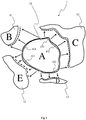
- Figure 1 shows a geometry image 1 associated with a 3D virtual scene, according to a specific and non-limitative embodiment.
- the 3D virtual scene comprises virtual objects, the surfaces of which being advantageously represented with a mesh of polygons defined with their vertices coordinates (x, y, z) expressed in the world space, i.e. the space of the 3D virtual scene.
- the geometry image 1 is advantageously obtained with the parameterization of the mesh using any existing multi-chart unwrapping methods such as the ones described in " Mesh parameterization methods and their applications” by Sheffer et al. (Foundation and Trends in Computer Graphics and Vision, 2(2): 105-171, 2006 ).
- the mesh is first segmented into a plurality of charts, wherein each chart corresponds to a piece of the 3D virtual scene, i.e. to a piece of the 3D surface defined by the mesh.
- the mesh charts are then mapped on a 2D grid of pixels, which corresponds to the geometry image 1.
- the geometry image 1 thus comprises a plurality of charts, each pixel of the chart being assigned mesh coordinates obtained by interpolation of the coordinates of the vertices of the mesh during a rasterizing process. Pixels located between two charts are not assigned any mesh coordinates as they do not correspond to any element of the 3D virtual scene.
- the geometry image 1 comprises 5 charts A 10, B 11, C 12, D 13 and 14, each chart having arbitrary boundaries and shapes.
- Indirection information is advantageously associated with pixels located at the border of the charts 10 to 14.
- the indirection information corresponds to indirection pointers that may be used to jump from a chart to another chart according to a determined direction.
- the indirection information is for example stored with the pixels forming the border of the chart. Such pixels may be called inner border pixels.
- the indirection information is stored with the pixels located outside from the chart but adjacent to the pixels forming the border of the chart. Such pixels may be called outer border pixels.
- first chart A 10 When taking the example of the chart A 10, called first chart A 10, the border comprising the inner border pixels is identified with the reference 100 and the outer border comprising the outer border pixels is identified with the references 101, 102, 103 and 104.
- the outer border 101 associated with the first chart A 10 faces the chart B 11.
- the outer border 102 associated with the first chart A 10 faces the chart C 12.
- the outer border 103 associated with the first chart A 10 faces the chart C 13.
- the outer border 104 associated with the first chart A 10 faces the chart D 14.
- Charts B 11, C 12, D 13 and E 14 will be called second charts in the rest of the description. Examples of determined directions for jumping from the first chart A 10 to a second chart B 11, C 12, D 13 or E 14 are illustrated with arrows on Figure 1 .
- inner border pixels or outer border pixels of the second charts may also comprise indirection information for jumping from a considered second chart to another second chart or to the first chart.
- the number of charts is not limited to 5 as in the example of figure 1 but extends to any number greater than or equal to 2 charts.
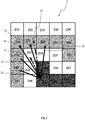
- Figure 2 shows a block 2 of pixels located at the border of the first chart of the geometry image 1, according to a specific and non-limitative embodiment.
- Pixels 201, 202, 203 and 204 shown in dark grey are called inner pixels as they are located inside the first chart and as they are different from pixels of the first chart forming the border of the first chart.
- Pixels 211, 212, 213, 214, 215, 216 and 217 shown in white are called inner border pixels as they belong to and form the border of the first chart.
- Each one of these pixels 211, 212, 213, 214, 215, 216 and 217 is adjacent to at least one of the inner pixels 201 to 204.
- Each inner pixel 201 to 204 and each inner border pixel 211 to 217 is assigned mesh coordinates corresponding to either the coordinates of a vertex of the mesh or to coordinates obtained by interpolating the coordinated of vertices of the mesh.
- Pixels 221, 222, 223, 224, 225, 226, 227, 228 and 229 shown in light grey are called outer border pixels as they do not belong to the first chart but correspond to the first pixels outside of the first chart crossed when scanning the geometry image 1 from any one of the inner pixels 201 to 204 toward the outside of the first chart.
- Each one of these outer border pixels 221 to 229 is adjacent to at least one of the inner border pixels 211 to 217.
- the outer border pixels 221 to 229 establish the boundary between the pixels of the first chart and the pixels not belonging to a chart. Pixels 231, 232, 233, 234 and 235 shown in white correspond to pixels not belonging to any chart and not belonging to any outer border of a chart. They correspond to pixels located between different charts and may also be called background pixels. Outer border pixels 221 to 229 and pixels 231 to 235 are not assigned mesh coordinates in contrast to pixels belonging to a chart as they do not refer to a surface of the 3D virtual scene.
- the arrow 20 corresponds to a determined direction, corresponding to an arbitrary direction.
- a determined direction may be used when reconstructing the 3D virtual scene from the geometry image 1.
- To reconstruct the 3D virtual scene it is necessary to put the charts back together by matching the borders of the charts.
- a reference direction 21 From the determined direction 20 is determined a reference direction 21, the reference direction 21 being computed from the mesh coordinates associated with the current pixel 203 (that corresponds to the origin of the determined direction 20) and from the mesh coordinates of the pixel 213, which is the first pixel of the border of the first chart crossed by the determined direction 20.
- the reference direction 21 is then advantageously compared with a set of candidate directions 22, 23, 24, 25 and 26.
- Each candidate direction is defined with the mesh coordinates associated with the current pixel 203 (which is the origin of the determined direction 20 and of the reference direction 21) and with indirection mesh coordinates associated with a pixel of the neighborhood of the first pixel 213. It is understood with neighborhood of the first pixel 213 pixels of the outer border adjacent to the first pixel 213, i.e. pixels 222, 223, 224, 225 and 226 on figure 2 .
- the indirection mesh coordinates associated with each pixel 222 to 226 correspond to the mesh coordinates of the pixel of the border of the second chart that would face the first chart when reconstructing the 3D virtual scene.
- the indirection mesh coordinates associated with the pixel 222 correspond to the mesh coordinates of the pixel of the border of the second chart that corresponds to the pixel 212 (respectively the pixel 223, 224, 225 and 226) of the border of the first chart.
- the pixel of the border of the second chart that corresponds to the pixel 212 (respectively the pixel 223, 224, 225 and 226) of the border of the first chart is advantageously determined by comparing the mesh coordinates of pixels of the border of the second chart with the mesh coordinates of the pixel 212 (respectively the pixel 223, 224, 225 and 226), the pixel of the border of the second chart corresponding to the pixel (respectively the pixel 223, 224, 225 and 226) being the one for which the difference between the mesh coordinates is minimal.
- the indirection mesh coordinates associated with the pixel 222 is determined by comparing mesh coordinates corresponding to the mean value of the mesh coordinates of the pixels of the inner border adjacent to the pixel 222 (i.e. pixels 211, 212 and 213) with mesh coordinates of pixels of the border of the second chart, the pixel of the border of the second chart corresponding to the pixel 222 being the one for which the difference between the mesh coordinates is minimal.
- a candidate direction corresponds to a direction passing by the current pixel 203 and a pixel of the second chart that is the pixel of the second chart corresponding to the pixel of the neighborhood associated with the candidate direction.
- Each candidate direction 22 to 26 is then compared with the reference direction 21 and the one for which the difference is minimal is selected.
- the selected candidate direction corresponds to the candidate direction the most parallel to the reference direction 21 among the set of candidate directions. Selecting a candidate direction enables to select the pixel of the border of the second chart associated with the candidate direction.
- the candidate direction the most parallel to the reference direction 21 is the candidate direction 24, which means that the pixel of the border of the second chart selected as corresponding to the first pixel 213 is the pixel of the border of the second chart, the mesh coordinates of which are associated with the pixel 224, while the determined direction passes 20 through the pixel 225 associated with another pixel of the border of the second chart.
- Such a difference may be for example due to the use of the mean mesh coordinates of pixels of the inner border for determining the pixel of the border of the second chart to be associated with pixels of the outer border of the first chart.
- the candidate direction is selected by using the following matching value computed for each k pixel 222, 223, 224, 225, and 226 of the neighborhood of the first pixel 213: innerPos ⁇ curPos
- curPos corresponds to the mesh coordinates of the current pixel, for example the pixel 203
- innerPos corresponds to the mesh coordinates of the first pixel 213,
- outerPos corresponds to the indirection mesh coordinates associated with the k pixels 222, 223, 224, 225, 226 of the neighborhood of the first pixel 213.
- the indirection pixel i.e. one of the pixel of the border of the second chart associated with one of the pixels 222 to 226) having the closest matching value to 1 is then selected as being the best matching pixel for indirection along the determined direction 20.
- pixels of the neighborhood of the first pixel 213 used to compute the candidate directions belong to the border of the first chart.
- the pixels of the neighborhood are for example the pixels of the inner border of the first chart equal to or adjacent to the first pixel 213, i.e. pixels 212, 213 and 214 in the exemplar embodiment of figure 2 .
- the mesh coordinates of the pixels 212, 213 and 214 are associated indirection mesh coordinates with each pixel 212, 213 and 214.
- the indirection mesh coordinates associated with each of these pixels, for example with the pixel 212 correspond to the mesh coordinates of a pixel of the border of the second chart corresponding to this pixel 212, i.e. the pixel of the border of the second chart having the mesh coordinates the closest with the mesh coordinates of the pixel 212.
- Figure 3 shows parts of the borders of the first chart 10 and of the second chart 11 of the geometry image 1, according to a specific and non-limitative embodiment.
- d1 31 corresponds advantageously to the candidate direction selected as being the best match to the determined direction 20.
- t1 32 represents the tangent vector to the border 300 at the first pixel 213, which corresponds to the first pixel of the border of the first chart 10 used for illustrating the exemplar embodiment of figure 2 .
- An angle ⁇ is formed by the two vectors d1 31 and t1 32.
- d2 34 corresponds advantageously to the marching direction corresponding to direction d1 31 when scanning the geometry image, for example for reconstruction purpose of the 3D virtual scene.
- T2 33 represents the tangent vector to the border 301 of the second chart 11 at a second pixel 313, which corresponds to the first pixel 213.
- the destination marching direction d2 34 is the rotation of t2 33 of - ⁇ + ⁇ .
- Adjacent charts i.e. the first and second charts
- Adjacent charts may have various orientations, according to the method used for organizing the charts within the geometry image. From this observation, the same marching direction from the first chart A 10 to a second chart, for example the second chart B 11, may be used only if their adjacent edges are parallel. However, as soon as different rotations are applied to adjacent charts, a new orientation for the marching direction has to be computed, when jumping from the first chart A to the second chart B. Thus, being on the first chart A 10 with a given first 2D marching direction d1 31, the consistent second 2D marching direction at the second chart B 11 is a rotation of the initial direction.
- the tangent t1 32 for the first chart 10 is estimated, as illustrated with regard to Figure 4A .
- the 1-ring neighborhood (pixels 422, 423, 431, 425, 426, 414, 413 and 412) is scanned in clockwise order.
- This tangent t1 is thus defined as: nextTexCoordTangent - nextTexCoord.
- Figure 4A uses the same convention with regard to the grey level for identifying the pixels as in figure 2 .
- the angle ⁇ between the tangent t1 and the 2D marching direction d1 31 is computed.
- the outer border pixel 424 at nextTexCoord redirects to the inner border pixel 462 of the second chart 11, at newTexCoord, as illustrated with regard to Figure 4B .
- the 1-ring neighborhood of this inner border pixel 462 is scanned.
- the first inner border pixel 463 after an inner pixel 451, with texture coordinates newTexCoordTangent is considered as being part of the tangent t2 33 at the second chart 11.
- the destination tangent t2 is thus defined as: newTexCoordTangent - newTexCoord.
- Figure 4B uses the same convention with regard to the grey level for identifying the pixels as in figure 2 .
- the destination 2D marching direction d2 34 is a rotation of the destination tangent t1 32 of - ⁇ + ⁇ .
- fetching only the 1-ring neighborhood to compute the tangents may give inconsistent results. For instance, if two adjacent chart borders are rasterized slightly differently, the rotation may be over-estimated.
- Better tangent estimation is provided by computing the tangent at various pixel distances.
- the final tangent computation is modulated for example with distances of one pixel, three pixels and five pixels border tangents. Mean of the intermediate tangents allows smoother tangent estimation.
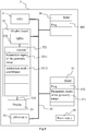
- Figure 5 diagrammatically shows a hardware embodiment of a device 5 configured for processing a geometry image such as the geometry image 1.
- the device 5 is also configured for the creation of display signals of one or several synthesis images representative of the 3D virtual scene reconstructed from the geometry image.
- the device 5 corresponds for example to a personal computer (PC), a laptop, a tablet, a Smartphone or a games console.
- the device 5 comprises the following elements, connected to each other by a bus 55 of addresses and data that also transports a clock signal:
- the device 5 also comprises a display device 53 of display screen type directly connected to the graphics card 52 to display synthesized images calculated and composed in the graphics card, for example live.
- a dedicated bus to connect the display device 53 to the graphics card 52 offers the advantage of having much greater data transmission bitrates and thus reducing the latency time for the displaying of images composed by the graphics card.
- a display device is external to the device 5 and is connected to the device 5 by a cable or wirelessly for transmitting the display signals.
- the device 5, for example the graphics card 52 comprises an interface for transmission or connection (not shown in figure 5 ) adapted to transmit a display signal to an external display means such as for example an LCD or plasma screen or a video-projector.
- register used in the description of memories 521, 56, and 57 designates in each of the memories mentioned, both a memory zone of low capacity (some binary data) as well as a memory zone of large capacity (enabling a whole program to be stored or all or part of the data representative of data calculated or to be displayed).
- the microprocessor 51 When switched-on, the microprocessor 51 loads and executes the instructions of the program contained in the RAM 57.
- the random access memory 57 notably comprises:
- the algorithms implementing the steps of the method specific to the present disclosure and described hereafter are stored in the memory GRAM 521 of the graphics card 52 associated with the device 5 implementing these steps.
- the graphic processors 520 of the graphics card 52 load these parameters into the GRAM 521 and execute the instructions of these algorithms in the form of microprograms of "shader" type using HLSL (High Level Shader Language) language or GLSL (OpenGL Shading Language) for example.
- HLSL High Level Shader Language
- GLSL OpenGL Shading Language
- the random access memory GRAM 521 notably comprises:
- the first and second identifiers and the distances are stored in the RAM 57 and processed by the microprocessor 51.
- a part of the RAM 57 is assigned by the CPU 51 for storage of the identifiers and the distances if the memory storage space available in GRAM 521 is insufficient.
- This variant however causes greater latency time in the composition of an image comprising a representation of the environment composed from microprograms contained in the GPUs as the data must be transmitted from the graphics card to the random access memory 57 passing by the bus 55 for which the transmission capacities are generally inferior to those available in the graphics card for transmission of data from the GPUs to the GRAM and vice-versa.
- the power supply 58 is external to the device 5.
- Figure 6 shows a method of processing a geometry image implemented for example in a device 5, according to a non-restrictive advantageous embodiment.
- the different parameters of the device 5 are updated.
- the parameters representative of the geometry image 1 are initialised in any way.
- a reference direction is computed by using values associated with two pixels of a first chart of a geometry image, the geometry image comprising a first chart and at least one second chart.
- the geometry image is the result of the parameterization process of a synthesis image representative of a 3D virtual scene represented with a mesh of polygons.
- the values used for computing the reference direction correspond advantageously to mesh coordinates associated with the pixels of the first chart, the mesh coordinates resulting from the parameterization process when rasterizing the geometry image.
- the two pixels of the first chart used for computing the reference direction correspond to a current pixel and a first pixel.
- the current pixel corresponds to one of the pixels of the chart but the pixels forming the border of the first chart.
- the first pixel corresponds to the first pixel of the border of the first chart crossed by a determined direction having as origin the current pixel.
- the determined direction is an arbitrary direction, also called first 2D marching direction as the determined direction correspond to a direction used for scanning the charts, for example when reconstructing the 3D virtual scene using the geometry image. Indeed, for reconstructing the 3D virtual scene from the charts, it is necessary to join charts with each other by respecting the borders, i.e. by matching pixels of the border of the first chart with pixels of the border of the second chart.
- each candidate direction is computing by using the mesh coordinates associated with the current pixel and with indirection mesh coordinates associated with one pixel belonging to the neighbourhood of the first pixel used for computing the reference direction.
- the indirection mesh coordinates advantageously correspond to the mesh coordinates of a pixel (called second pixel) of the border of a second chart, the second pixel being the pixel of the second chart that corresponds to the pixel of the neighbourhood of the first pixel used for computing the reference direction.
- a pixel of the border of the second chart (the second chart being the complementary chart of the first chart according to the determined direction) is said corresponding pixel of the pixel of the neighbourhood of the first pixel when the mesh coordinates of this second pixel are the closest to the mesh coordinates associated with the pixel of the neighbourhood (used for computing the candidate direction) among a plurality of pixels of the border of the second chart complementary to the first chart.
- the second pixel is for example determined by comparing the mesh coordinates of a plurality of pixels of the border of the second chart with the mesh coordinates associated with the pixel of the neighbourhood of the first pixel and by selecting the pixel of the border of the second chart for which the difference between the mesh coordinates is minimal in comparison with the other pixels of the border of the second chart.
- Pixels belonging to the neighbourhood of the first pixel and used for computing the candidate directions advantageously belong to 1-ring pixels surrounding the first pixel and adjacent to the first pixel but not belonging to the first chart.
- the pixels of the neighbourhood of the first pixels are some of the pixels located outside the first chart but adjacent to the border of the first chart (and adjacent to the first pixel). These pixels of the neighbourhood correspond to the outer border of the first chart and form the first line of pixels outside the first chart and surrounding the first chart. It is advantageous to use these outer border pixels for computing the candidate directions as there is no mesh coordinates associated with them (as they do not refer to any object's surface of the 3D virtual scene as outside of the charts) as a result of the parameterization process.
- the indirection mesh coordinates associated with each of these outer border pixels is determined as explained hereinabove by comparing the mesh coordinates of pixels of the border of the second chart with mesh coordinates associated with this outer border pixel. As there is no mesh coordinates associated with this outer border pixel as a result of the parameterization process, the mesh coordinates used for the comparison correspond to the mesh coordinates associated with the pixel of the border of the first chart which is fully adjacent to this outer border pixel.
- the mesh coordinates to be used for the comparison correspond to a mean of the mesh coordinates of several pixels (for example 2, 3, 4 or 5) of the border of the first chart, for example pixels of the border of the first chart being in contact with the pixel of the outer border pixel.
- Pixels belonging to the neighbourhood of the first pixel and used for computing the candidate directions correspond to pixels of the border of the first chart being in contact with the first pixel, including the first pixel.
- a pixel of the border of the second chart is selected as being the corresponding pixel of the first pixel, the selection of this pixel of the second chart being based on the result of the comparison between the reference direction and each candidate direction.
- the selection of a pixel of the border of the second chart for being the corresponding pixel of the first pixel enable to put back together the first chart and the second chart (for example when reconstructing the 3D virtual scene from the geometry image) by matching the pixels of the border of the first chart with pixels of the border of the second chart by best respecting the coherence of the mesh (represented with the mesh coordinates associated with the pixels of the first and second charts).
- the selected pixel of the border of the second chart is the one for which the associated candidate direction (among the plurality of candidate direction used in the comparison step) is the most parallel to the reference direction.
- the selected pixel corresponds to the pixel for which the difference between the reference direction and the candidate direction associated to this selected pixel is minimal with regard to the differences between the reference direction and the other candidate directions.
- steps 61 to 63 may be reiterated for several different determined directions and/or for several different current pixels of the first chart or of other chart different from the first chart.
- the method further comprises a step of determining a direction for scanning the second chart, called second 2D marching direction.
- This second 2D marching direction enables to scan the second chart according to a direction that corresponds to the determined direction.
- This second 2D marching direction is advantageously determined by using the determined direction (which is also called the first 2D marching direction), the tangent to the border of the first chart at the first pixel and the tangent to the border of the second chart at the selected pixel.
- the present disclosure is not limited to a method of processing a geometry image but also extends to any device implementing this method and notably any devices comprising at least one GPU.
- the implementation of calculations necessary to the processing of the geometry image is not limited either to an implementation in shader type microprograms but also extends to an implementation in any program type, for example programs that can be executed by a CPU type microprocessor.
- the use of the methods of the present disclosure is not limited to a live utilisation but also extends to any other utilisation, for example for processing known as postproduction processing in a recording studio for the display of synthesis images for example.
- the present disclosure also relates to a method (and a device configured) for reconstructing a 3D virtual scene (or part of it) from a geometry image.
- the implementations described herein may be implemented in, for example, a method or a process, an apparatus, a software program, a data stream, or a signal. Even if only discussed in the context of a single form of implementation (for example, discussed only as a method or a device), the implementation of features discussed may also be implemented in other forms (for example a program).
- An apparatus may be implemented in, for example, appropriate hardware, software, and firmware.
- the methods may be implemented in, for example, an apparatus such as, for example, a processor, which refers to processing devices in general, including, for example, a computer, a microprocessor, an integrated circuit, or a programmable logic device. Processors also include communication devices, such as, for example, Smartphones, tablets, computers, mobile phones, portable/personal digital assistants ("PDAs”), and other devices that facilitate communication of information between end-users.
- PDAs portable/personal digital assistants
- Implementations of the various processes and features described herein may be embodied in a variety of different equipment or applications, particularly, for example, equipment or applications associated with data encoding, data decoding, view generation, texture processing, and other processing of images and related texture information and/or depth information.
- equipment include an encoder, a decoder, a post-processor processing output from a decoder, a pre-processor providing input to an encoder, a video coder, a video decoder, a video codec, a web server, a set-top box, a laptop, a personal computer, a cell phone, a PDA, and other communication devices.
- the equipment may be mobile and even installed in a mobile vehicle.
- the methods may be implemented by instructions being performed by a processor, and such instructions (and/or data values produced by an implementation) may be stored on a processor-readable medium such as, for example, an integrated circuit, a software carrier or other storage device such as, for example, a hard disk, a compact diskette (“CD"), an optical disc (such as, for example, a DVD, often referred to as a digital versatile disc or a digital video disc), a random access memory (“RAM”), or a read-only memory (“ROM”).
- the instructions may form an application program tangibly embodied on a processor-readable medium. Instructions may be, for example, in hardware, firmware, software, or a combination.
- a processor may be characterized, therefore, as, for example, both a device configured to carry out a process and a device that includes a processor-readable medium (such as a storage device) having instructions for carrying out a process. Further, a processor-readable medium may store, in addition to or in lieu of instructions, data values produced by an implementation.
- implementations may produce a variety of signals formatted to carry information that may be, for example, stored or transmitted.
- the information may include, for example, instructions for performing a method, or data produced by one of the described implementations.
- a signal may be formatted to carry as data the rules for writing or reading the syntax of a described embodiment, or to carry as data the actual syntax-values written by a described embodiment.
- Such a signal may be formatted, for example, as an electromagnetic wave (for example, using a radio frequency portion of spectrum) or as a baseband signal.
- the formatting may include, for example, encoding a data stream and modulating a carrier with the encoded data stream.
- the information that the signal carries may be, for example, analog or digital information.
- the signal may be transmitted over a variety of different wired or wireless links, as is known.
- the signal may be stored on a processor-readable medium.
Landscapes
- Engineering & Computer Science (AREA)
- Physics & Mathematics (AREA)
- Computer Graphics (AREA)
- General Physics & Mathematics (AREA)
- Theoretical Computer Science (AREA)
- Geometry (AREA)
- Software Systems (AREA)
- Image Generation (AREA)
- Image Processing (AREA)
Claims (11)
- Computerimplementiertes Verfahren zur Verarbeitung eines Geometriebilds (1), wobei das Geometriebild (1) aus einem Flächennetz erzeugt wird, das einer 3D-Szene zugeordnet ist, wobei das Geometriebild eine erste Teilfläche (10) und mindestens eine zweite Teilfläche (11, 12, 13, 14) umfasst, wobei jede erste und zweite Teilfläche einen Teil der 3D-Szene darstellt, dadurch gekennzeichnet, dass das Verfahren für mindestens ein gegenwärtiges Pixel (203) der ersten Teilfläche (10), das von Pixeln (211 bis 217) der ersten Teilfläche, die die Begrenzung der ersten Teilfläche bilden, verschieden ist, Folgendes umfasst:- Berechnen (61) einer Bezugsrichtung (21) aus Flächennetzkoordinaten, die einem ersten Pixel (213) zugeordnet sind, wobei das erste Pixel (213) einem Pixel der Begrenzung der ersten Teilfläche, die von einer vorgegebenen Richtung (20), die als Ursprung das mindestens eine gegenwärtige Pixel (203) besitzt, durchquert wird, entspricht, wobei das mindestens eine gegenwärtige Pixel (203) einen Ursprung der Bezugsrichtung (21) bildet,- Vergleichen (62) der Bezugsrichtung (21) mit einer Menge von Kandidatenrichtungen (22, 23, 24, 25, 26), wobei jede Kandidatenrichtung aus den Flächennetzkoordinaten, die dem mindestens einen gegenwärtigen Pixel (203) zugeordnet sind, und aus Umwegflächennetzkoordinaten, die einem Pixel (222 bis 226; 212 bis 214) der Nachbarschaft des ersten Pixels (213) zugeordnet sind, berechnet wird, wobei die Umwegflächennetzkoordinaten Flächennetzkoordinaten eines zweiten Pixels der Begrenzung des mindestens einen zweiten Teilflächenpixels, das dem Pixel der Nachbarschaft des ersten Pixels entspricht, entsprechen, wobei das zweite Pixel dasjenige Pixel ist, für das die Differenz zwischen seinen Flächennetzkoordinaten und den Flächennetzkoordinaten des Pixels der Nachbarschaft des ersten Pixels minimal ist, wobei die Nachbarschaft des ersten Pixels Pixel einer Außenbegrenzung der ersten Teilfläche (10) und Pixel der Begrenzung der ersten Teilfläche (10) umfasst, wobei die Außenbegrenzung Pixel, die sich außerhalb der ersten Teilfläche befinden und die an Pixel, die die Begrenzung der ersten Teilfläche bilden, angrenzen, umfasst,- Auswählen (63) eines Pixels der Begrenzung der mindestens einen zweiten Teilfläche (11, 12, 13, 14) in Übereinstimmung mit dem Vergleichsergebnis, wobei das ausgewählte Pixel demjenigen Pixel, für das die Differenz zwischen der Bezugsrichtung (21) und der Kandidatenrichtung (24), die dem ausgewählten Pixel zugeordnet ist, in Bezug auf die Differenzen zwischen der Bezugsrichtung (21) und den anderen Kandidatenrichtungen (22 bis 26) minimal ist, entspricht;- Bestimmen einer Abtastrichtung (34) zum Abtasten der mindestens einen zweiten Teilfläche (11), die der bestimmten Richtung entspricht, wobei die Abtastrichtung (34) in Übereinstimmung mit der bestimmten Richtung (31), mit einer Tangente (32) an die Begrenzung der ersten Teilfläche (10) bei dem ersten Pixel (213) und mit einer Tangente (33) an die Begrenzung der mindestens einen zweiten Teilfläche (11) des ausgewählten Pixels (313) bestimmt wird.
- Verfahren nach Anspruch 1, wobei die Pixel (211 bis 213) der Nachbarschaft des ersten Pixels (213), die zum Berechnen von Kandidatenrichtungen verwendet werden, zu der Begrenzung der ersten Teilfläche (10) gehören.
- Verfahren nach Anspruch 1, wobei die Pixel (222 bis 226) der Nachbarschaft des ersten Pixels (213), die zum Berechnen von Kandidatenrichtungen verwendet werden, außerhalb der Begrenzung der ersten Teilfläche (10) und angrenzend an das erste Pixel (213) sind.
- Verfahren nach einem der Ansprüche 1 bis 3, wobei das Pixel der Begrenzung der mindestens einen zweiten Teilfläche (11, 12, 13, 14), das dem Pixel der Nachbarschaft des ersten Pixels (213) entspricht, durch Vergleichen der Flächennetzkoordinaten des Pixels der Nachbarschaft des ersten Pixels mit Flächennetzkoordinaten mehrerer Pixel der Begrenzung der mindestens einen zweiten Teilfläche bestimmt wird, wobei das bestimmte Pixel der Begrenzung der mindestens einen zweiten Teilfläche dasjenige Pixel ist, für das die Differenz zwischen seinen Flächennetzkoordinaten und den Flächennetzkoordinaten des Pixels der Nachbarschaft des ersten Pixels minimal ist.
- Vorrichtung (5), die dafür konfiguriert ist, ein Geometriebild zu verarbeiten, wobei das Geometriebild aus einem Flächennetz erzeugt wird, das einer 3D-Szene zugeordnet ist, wobei das Geometriebild eine erste Teilfläche und mindestens eine zweite Teilfläche umfasst, wobei jede erste und zweite Teilfläche einen Teil der 3D-Szene darstellt, dadurch gekennzeichnet, dass die Vorrichtung mindestens einen Prozessor (520) umfasst, der für mindestens ein gegenwärtiges Pixel der ersten Teilfläche, das von Pixeln der ersten Teilfläche, die die Begrenzung der ersten Teilfläche bilden, verschieden ist, für Folgendes konfiguriert ist:- Berechnen einer Bezugsrichtung aus Flächennetzkoordinaten, die dem mindestens einen gegenwärtigen Pixel zugeordnet sind, und aus Flächennetzkoordinaten, die einem ersten Pixel zugeordnet sind, wobei das erste Pixel einem Pixel der Begrenzung der ersten Teilfläche, die von einer vorgegebenen Richtung, die als Ursprung das mindestens eine gegenwärtige Pixel besitzt, durchquert wird, entspricht, wobei das mindestens eine gegenwärtige Pixel einen Ursprung der Bezugsrichtung bildet,- Vergleichen der Bezugsrichtung mit einer Menge von Kandidatenrichtungen, wobei jede Kandidatenrichtung aus den Flächennetzkoordinaten, die dem mindestens einen gegenwärtigen Pixel zugeordnet sind, und aus Umwegflächennetzkoordinaten, die einem Pixel der Nachbarschaft des ersten Pixels zugeordnet sind, berechnet wird, wobei die Umwegflächennetzkoordinaten Flächennetzkoordinaten eines zweiten Pixels der Begrenzung des mindestens einen zweiten Teilflächenpixels, das dem Pixel der Nachbarschaft des ersten Pixels entspricht, entsprechen, wobei das zweite Pixel dasjenige Pixel ist, für das die Differenz zwischen seinen Flächennetzkoordinaten und den Flächennetzkoordinaten des Pixels der Nachbarschaft des ersten Pixels minimal ist, wobei die Nachbarschaft des ersten Pixels Pixel einer Außenbegrenzung der ersten Teilfläche und Pixel der Begrenzung der ersten Teilfläche umfasst, wobei die Außenbegrenzung Pixel, die sich außerhalb der ersten Teilfläche befinden und die an Pixel, die die Begrenzung der ersten Teilfläche bilden, angrenzen, umfasst,- Auswählen eines Pixels der Begrenzung der mindestens einen zweiten Teilfläche in Übereinstimmung mit dem Vergleichsergebnis, wobei das ausgewählte Pixel demjenigen Pixel, für das die Differenz zwischen der Bezugsrichtung und der Kandidatenrichtung, die dem ausgewählten Pixel zugeordnet ist, in Bezug auf die Differenzen zwischen der Bezugsrichtung und den anderen Kandidatenrichtungen minimal ist, entspricht;- Bestimmen einer Abtastrichtung (34) zum Abtasten der mindestens einen zweiten Teilfläche (11), die der bestimmten Richtung entspricht, wobei die Abtastrichtung (34) in Übereinstimmung mit der bestimmten Richtung (31), mit einer Tangente (32) an die Begrenzung der ersten Teilfläche (10) bei dem ersten Pixel (213) und mit einer Tangente an die Begrenzung der mindestens einen zweiten Teilfläche (11) des ausgewählten Pixels (313) bestimmt wird.
- Vorrichtung (5) nach Anspruch 5, wobei die Pixel der Nachbarschaft des ersten Pixels, die zum Berechnen von Kandidatenrichtungen verwendet werden, zu der Begrenzung der ersten Teilfläche gehören.
- Vorrichtung (5) nach Anspruch 5, wobei die Pixel der Nachbarschaft des ersten Pixels, die zum Berechnen von Kandidatenrichtungen verwendet werden, außerhalb der Begrenzung der ersten Teilfläche und angrenzend an das ausgewählte Pixel sind.
- Vorrichtung (5) nach einem der Ansprüche 5 bis 7, wobei der mindestens eine Prozessor (520) ferner dafür konfiguriert ist, die Flächennetzkoordinaten des Pixels der Nachbarschaft des ersten Pixels mit Flächennetzkoordinaten mehrerer Pixel der Begrenzung der mindestens einen zweiten Teilfläche zu vergleichen, um dasjenige Pixel der Begrenzung der mindestens einen zweiten Teilfläche zu bestimmen, das dem Pixel der Nachbarschaft des ersten Pixels entspricht, wobei das bestimmte Pixel der Begrenzung der mindestens einen zweiten Teilfläche dasjenige Pixel ist, für das die Differenz zwischen seinen Flächennetzkoordinaten und den Flächennetzkoordinaten des Pixels der Nachbarschaft des ersten Pixels minimal ist.
- Vorrichtung (5) nach einem der Ansprüche 5 bis 8, wobei der mindestens eine Prozessor (520) eine Graphikprozessoreinheit (GPU) ist.
- Computerprogrammprodukt, dadurch gekennzeichnet, dass es Anweisungen von Programmcode zum Ausführen von Schritten des Verfahrens nach einem der Ansprüche 1 bis 4, wenn das Programm in einem Computer ausgeführt wird, umfasst.
- Prozessorlesbares Medium, in dem Anweisungen gespeichert sind, um zu veranlassen, dass ein Prozessor mindestens die Schritte des Verfahrens nach einem der Ansprüche 1 bis 4 ausführt.
Priority Applications (5)
| Application Number | Priority Date | Filing Date | Title |
|---|---|---|---|
| EP14305145.6A EP2902973B1 (de) | 2014-02-03 | 2014-02-03 | Verfahren und Vorrichtung zur Verarbeitung eines Geometriebildes einer 3D-Szene |
| JP2015011216A JP2015146181A (ja) | 2014-02-03 | 2015-01-23 | 3dシーンの幾何学図形的配列画像を処理するための方法および装置 |
| US14/611,323 US9747720B2 (en) | 2014-02-03 | 2015-02-02 | Method and device for processing a geometry image of a 3D scene |
| KR1020150016099A KR20150099414A (ko) | 2014-02-03 | 2015-02-02 | 3d 장면의 기하 이미지를 처리하는 방법 및 장치 |
| CN201510055039.8A CN104821008A (zh) | 2014-02-03 | 2015-02-03 | 用于处理三维场景的几何图像的方法和设备 |
Applications Claiming Priority (1)
| Application Number | Priority Date | Filing Date | Title |
|---|---|---|---|
| EP14305145.6A EP2902973B1 (de) | 2014-02-03 | 2014-02-03 | Verfahren und Vorrichtung zur Verarbeitung eines Geometriebildes einer 3D-Szene |
Publications (2)
| Publication Number | Publication Date |
|---|---|
| EP2902973A1 EP2902973A1 (de) | 2015-08-05 |
| EP2902973B1 true EP2902973B1 (de) | 2018-06-27 |
Family
ID=50137595
Family Applications (1)
| Application Number | Title | Priority Date | Filing Date |
|---|---|---|---|
| EP14305145.6A Active EP2902973B1 (de) | 2014-02-03 | 2014-02-03 | Verfahren und Vorrichtung zur Verarbeitung eines Geometriebildes einer 3D-Szene |
Country Status (5)
| Country | Link |
|---|---|
| US (1) | US9747720B2 (de) |
| EP (1) | EP2902973B1 (de) |
| JP (1) | JP2015146181A (de) |
| KR (1) | KR20150099414A (de) |
| CN (1) | CN104821008A (de) |
Families Citing this family (10)
| Publication number | Priority date | Publication date | Assignee | Title |
|---|---|---|---|---|
| WO2016134048A1 (en) | 2015-02-17 | 2016-08-25 | Nextvr Inc. | Methods and apparatus for generating and using reduced resolution images and/or communicating such images to a playback or content distribution device |
| US10362290B2 (en) | 2015-02-17 | 2019-07-23 | Nextvr Inc. | Methods and apparatus for processing content based on viewing information and/or communicating content |
| TWI564866B (zh) * | 2015-07-03 | 2017-01-01 | 點晶科技股份有限公司 | 顯示器及其顯示方法 |
| US9875578B2 (en) * | 2015-10-13 | 2018-01-23 | Biosense Webster (Israel) Ltd. | Voxelization of a mesh |
| US10282888B2 (en) * | 2016-01-28 | 2019-05-07 | Biosense Webster (Israel) Ltd. | High definition coloring of heart chambers |
| CN109274951B (zh) * | 2017-07-13 | 2020-11-10 | 富泰华工业(深圳)有限公司 | 深度计算方法及其装置 |
| AU2018203327A1 (en) | 2018-05-11 | 2019-11-28 | Canon Kabushiki Kaisha | System and method for processing a graphic object |
| CN112017292B (zh) * | 2019-05-31 | 2025-05-06 | 华为技术有限公司 | 网格译码方法和装置 |
| CN112449078A (zh) * | 2019-08-29 | 2021-03-05 | 福建天泉教育科技有限公司 | 一种生成缩略图的方法及终端 |
| CN117838991B (zh) * | 2024-03-07 | 2024-05-10 | 深圳市美迪泰克医药有限公司 | 一种用于口腔麻醉的电子助推仪及该助推仪的标定方法 |
Family Cites Families (6)
| Publication number | Priority date | Publication date | Assignee | Title |
|---|---|---|---|---|
| CN1278553C (zh) * | 2003-05-23 | 2006-10-04 | 华亚微电子(上海)有限公司 | 一种像素静止检测的多窗口多阈值方法 |
| US7265752B2 (en) | 2004-01-09 | 2007-09-04 | Microsoft Corporation | Multi-chart geometry images |
| US7733350B2 (en) * | 2006-06-30 | 2010-06-08 | Microsoft Corporation | Anisometric texture synthesis |
| US20080166071A1 (en) * | 2007-01-10 | 2008-07-10 | Alexandru Serbanescu | Data processing method & device |
| JP5482394B2 (ja) * | 2009-05-13 | 2014-05-07 | セイコーエプソン株式会社 | 画像処理方法および画像処理装置 |
| WO2013133757A2 (en) * | 2012-03-09 | 2013-09-12 | Flatfrog Laboratories Ab | Efficient tomographic processing for touch determination |
-
2014
- 2014-02-03 EP EP14305145.6A patent/EP2902973B1/de active Active
-
2015
- 2015-01-23 JP JP2015011216A patent/JP2015146181A/ja active Pending
- 2015-02-02 KR KR1020150016099A patent/KR20150099414A/ko not_active Withdrawn
- 2015-02-02 US US14/611,323 patent/US9747720B2/en active Active
- 2015-02-03 CN CN201510055039.8A patent/CN104821008A/zh active Pending
Non-Patent Citations (1)
| Title |
|---|
| None * |
Also Published As
| Publication number | Publication date |
|---|---|
| US20150221129A1 (en) | 2015-08-06 |
| CN104821008A (zh) | 2015-08-05 |
| US9747720B2 (en) | 2017-08-29 |
| EP2902973A1 (de) | 2015-08-05 |
| KR20150099414A (ko) | 2015-08-31 |
| JP2015146181A (ja) | 2015-08-13 |
Similar Documents
| Publication | Publication Date | Title |
|---|---|---|
| EP2902973B1 (de) | Verfahren und Vorrichtung zur Verarbeitung eines Geometriebildes einer 3D-Szene | |
| JP6728316B2 (ja) | フィルタリングされた粗ピクセルシェーディングのための方法および装置 | |
| US11481974B2 (en) | Mesh optimization for computer graphics | |
| US10089774B2 (en) | Tessellation in tile-based rendering | |
| EP3021286A1 (de) | Vorrichtung und Verfahren zur Berechnung von Schatten in einer 3D-Szene | |
| US10074211B2 (en) | Method and device for establishing the frontier between objects of a scene in a depth map | |
| US9898838B2 (en) | Graphics processing apparatus and method for determining level of detail (LOD) for texturing in graphics pipeline | |
| US11989807B2 (en) | Rendering scalable raster content | |
| JP2015515059A (ja) | シーンにおける不透明度レベルを推定する方法とそれに対応する装置 | |
| KR20240163125A (ko) | 초고해상도 업스케일링 | |
| US10062138B2 (en) | Rendering apparatus and method | |
| US10192348B2 (en) | Method and apparatus for processing texture | |
| US9607435B2 (en) | Method for rendering an image synthesis and corresponding device | |
| US11776179B2 (en) | Rendering scalable multicolored vector content | |
| JP2016511962A (ja) | 内挿方法および対応する装置 | |
| US20240161236A1 (en) | Method and apparatus with adaptive super sampling | |
| US20190279421A1 (en) | Removal of degenerated sub-primitives in tessellation | |
| EP2902971A1 (de) | Verfahren und Vorrichtung zur Verformung der Geometrie einer virtuellen 3D-Szene | |
| Mostafavian et al. | A novel edge-preserving mesh-based method for image scaling |
Legal Events
| Date | Code | Title | Description |
|---|---|---|---|
| PUAI | Public reference made under article 153(3) epc to a published international application that has entered the european phase |
Free format text: ORIGINAL CODE: 0009012 |
|
| 17P | Request for examination filed |
Effective date: 20140203 |
|
| AK | Designated contracting states |
Kind code of ref document: A1 Designated state(s): AL AT BE BG CH CY CZ DE DK EE ES FI FR GB GR HR HU IE IS IT LI LT LU LV MC MK MT NL NO PL PT RO RS SE SI SK SM TR |
|
| AX | Request for extension of the european patent |
Extension state: BA ME |
|
| 17P | Request for examination filed |
Effective date: 20160128 |
|
| RBV | Designated contracting states (corrected) |
Designated state(s): AL AT BE BG CH CY CZ DE DK EE ES FI FR GB GR HR HU IE IS IT LI LT LU LV MC MK MT NL NO PL PT RO RS SE SI SK SM TR |
|
| GRAP | Despatch of communication of intention to grant a patent |
Free format text: ORIGINAL CODE: EPIDOSNIGR1 |
|
| STAA | Information on the status of an ep patent application or granted ep patent |
Free format text: STATUS: GRANT OF PATENT IS INTENDED |
|
| INTG | Intention to grant announced |
Effective date: 20180115 |
|
| GRAS | Grant fee paid |
Free format text: ORIGINAL CODE: EPIDOSNIGR3 |
|
| GRAA | (expected) grant |
Free format text: ORIGINAL CODE: 0009210 |
|
| STAA | Information on the status of an ep patent application or granted ep patent |
Free format text: STATUS: THE PATENT HAS BEEN GRANTED |
|
| AK | Designated contracting states |
Kind code of ref document: B1 Designated state(s): AL AT BE BG CH CY CZ DE DK EE ES FI FR GB GR HR HU IE IS IT LI LT LU LV MC MK MT NL NO PL PT RO RS SE SI SK SM TR |
|
| REG | Reference to a national code |
Ref country code: GB Ref legal event code: FG4D |
|
| REG | Reference to a national code |
Ref country code: DE Ref legal event code: R084 Ref document number: 602014027492 Country of ref document: DE |
|
| REG | Reference to a national code |
Ref country code: AT Ref legal event code: REF Ref document number: 1012979 Country of ref document: AT Kind code of ref document: T Effective date: 20180715 |
|
| REG | Reference to a national code |
Ref country code: IE Ref legal event code: FG4D |
|
| REG | Reference to a national code |
Ref country code: DE Ref legal event code: R096 Ref document number: 602014027492 Country of ref document: DE |
|
| PG25 | Lapsed in a contracting state [announced via postgrant information from national office to epo] |
Ref country code: SE Free format text: LAPSE BECAUSE OF FAILURE TO SUBMIT A TRANSLATION OF THE DESCRIPTION OR TO PAY THE FEE WITHIN THE PRESCRIBED TIME-LIMIT Effective date: 20180627 Ref country code: NO Free format text: LAPSE BECAUSE OF FAILURE TO SUBMIT A TRANSLATION OF THE DESCRIPTION OR TO PAY THE FEE WITHIN THE PRESCRIBED TIME-LIMIT Effective date: 20180927 Ref country code: FI Free format text: LAPSE BECAUSE OF FAILURE TO SUBMIT A TRANSLATION OF THE DESCRIPTION OR TO PAY THE FEE WITHIN THE PRESCRIBED TIME-LIMIT Effective date: 20180627 Ref country code: BG Free format text: LAPSE BECAUSE OF FAILURE TO SUBMIT A TRANSLATION OF THE DESCRIPTION OR TO PAY THE FEE WITHIN THE PRESCRIBED TIME-LIMIT Effective date: 20180927 Ref country code: LT Free format text: LAPSE BECAUSE OF FAILURE TO SUBMIT A TRANSLATION OF THE DESCRIPTION OR TO PAY THE FEE WITHIN THE PRESCRIBED TIME-LIMIT Effective date: 20180627 |
|
| REG | Reference to a national code |
Ref country code: NL Ref legal event code: MP Effective date: 20180627 |
|
| REG | Reference to a national code |
Ref country code: LT Ref legal event code: MG4D |
|
| PG25 | Lapsed in a contracting state [announced via postgrant information from national office to epo] |
Ref country code: GR Free format text: LAPSE BECAUSE OF FAILURE TO SUBMIT A TRANSLATION OF THE DESCRIPTION OR TO PAY THE FEE WITHIN THE PRESCRIBED TIME-LIMIT Effective date: 20180928 Ref country code: LV Free format text: LAPSE BECAUSE OF FAILURE TO SUBMIT A TRANSLATION OF THE DESCRIPTION OR TO PAY THE FEE WITHIN THE PRESCRIBED TIME-LIMIT Effective date: 20180627 Ref country code: HR Free format text: LAPSE BECAUSE OF FAILURE TO SUBMIT A TRANSLATION OF THE DESCRIPTION OR TO PAY THE FEE WITHIN THE PRESCRIBED TIME-LIMIT Effective date: 20180627 Ref country code: RS Free format text: LAPSE BECAUSE OF FAILURE TO SUBMIT A TRANSLATION OF THE DESCRIPTION OR TO PAY THE FEE WITHIN THE PRESCRIBED TIME-LIMIT Effective date: 20180627 |
|
| REG | Reference to a national code |
Ref country code: AT Ref legal event code: MK05 Ref document number: 1012979 Country of ref document: AT Kind code of ref document: T Effective date: 20180627 |
|
| PG25 | Lapsed in a contracting state [announced via postgrant information from national office to epo] |
Ref country code: NL Free format text: LAPSE BECAUSE OF FAILURE TO SUBMIT A TRANSLATION OF THE DESCRIPTION OR TO PAY THE FEE WITHIN THE PRESCRIBED TIME-LIMIT Effective date: 20180627 |
|
| PG25 | Lapsed in a contracting state [announced via postgrant information from national office to epo] |
Ref country code: CZ Free format text: LAPSE BECAUSE OF FAILURE TO SUBMIT A TRANSLATION OF THE DESCRIPTION OR TO PAY THE FEE WITHIN THE PRESCRIBED TIME-LIMIT Effective date: 20180627 Ref country code: RO Free format text: LAPSE BECAUSE OF FAILURE TO SUBMIT A TRANSLATION OF THE DESCRIPTION OR TO PAY THE FEE WITHIN THE PRESCRIBED TIME-LIMIT Effective date: 20180627 Ref country code: AT Free format text: LAPSE BECAUSE OF FAILURE TO SUBMIT A TRANSLATION OF THE DESCRIPTION OR TO PAY THE FEE WITHIN THE PRESCRIBED TIME-LIMIT Effective date: 20180627 Ref country code: EE Free format text: LAPSE BECAUSE OF FAILURE TO SUBMIT A TRANSLATION OF THE DESCRIPTION OR TO PAY THE FEE WITHIN THE PRESCRIBED TIME-LIMIT Effective date: 20180627 Ref country code: IS Free format text: LAPSE BECAUSE OF FAILURE TO SUBMIT A TRANSLATION OF THE DESCRIPTION OR TO PAY THE FEE WITHIN THE PRESCRIBED TIME-LIMIT Effective date: 20181027 Ref country code: PL Free format text: LAPSE BECAUSE OF FAILURE TO SUBMIT A TRANSLATION OF THE DESCRIPTION OR TO PAY THE FEE WITHIN THE PRESCRIBED TIME-LIMIT Effective date: 20180627 Ref country code: SK Free format text: LAPSE BECAUSE OF FAILURE TO SUBMIT A TRANSLATION OF THE DESCRIPTION OR TO PAY THE FEE WITHIN THE PRESCRIBED TIME-LIMIT Effective date: 20180627 |
|
| PG25 | Lapsed in a contracting state [announced via postgrant information from national office to epo] |
Ref country code: IT Free format text: LAPSE BECAUSE OF FAILURE TO SUBMIT A TRANSLATION OF THE DESCRIPTION OR TO PAY THE FEE WITHIN THE PRESCRIBED TIME-LIMIT Effective date: 20180627 Ref country code: SM Free format text: LAPSE BECAUSE OF FAILURE TO SUBMIT A TRANSLATION OF THE DESCRIPTION OR TO PAY THE FEE WITHIN THE PRESCRIBED TIME-LIMIT Effective date: 20180627 Ref country code: ES Free format text: LAPSE BECAUSE OF FAILURE TO SUBMIT A TRANSLATION OF THE DESCRIPTION OR TO PAY THE FEE WITHIN THE PRESCRIBED TIME-LIMIT Effective date: 20180627 |
|
| REG | Reference to a national code |
Ref country code: DE Ref legal event code: R097 Ref document number: 602014027492 Country of ref document: DE |
|
| PLBE | No opposition filed within time limit |
Free format text: ORIGINAL CODE: 0009261 |
|
| STAA | Information on the status of an ep patent application or granted ep patent |
Free format text: STATUS: NO OPPOSITION FILED WITHIN TIME LIMIT |
|
| PG25 | Lapsed in a contracting state [announced via postgrant information from national office to epo] |
Ref country code: DK Free format text: LAPSE BECAUSE OF FAILURE TO SUBMIT A TRANSLATION OF THE DESCRIPTION OR TO PAY THE FEE WITHIN THE PRESCRIBED TIME-LIMIT Effective date: 20180627 |
|
| 26N | No opposition filed |
Effective date: 20190328 |
|
| PG25 | Lapsed in a contracting state [announced via postgrant information from national office to epo] |
Ref country code: SI Free format text: LAPSE BECAUSE OF FAILURE TO SUBMIT A TRANSLATION OF THE DESCRIPTION OR TO PAY THE FEE WITHIN THE PRESCRIBED TIME-LIMIT Effective date: 20180627 |
|
| REG | Reference to a national code |
Ref country code: CH Ref legal event code: PL |
|
| GBPC | Gb: european patent ceased through non-payment of renewal fee |
Effective date: 20190203 |
|
| PG25 | Lapsed in a contracting state [announced via postgrant information from national office to epo] |
Ref country code: MC Free format text: LAPSE BECAUSE OF FAILURE TO SUBMIT A TRANSLATION OF THE DESCRIPTION OR TO PAY THE FEE WITHIN THE PRESCRIBED TIME-LIMIT Effective date: 20180627 Ref country code: LU Free format text: LAPSE BECAUSE OF NON-PAYMENT OF DUE FEES Effective date: 20190203 |
|
| REG | Reference to a national code |
Ref country code: BE Ref legal event code: MM Effective date: 20190228 |
|
| REG | Reference to a national code |
Ref country code: IE Ref legal event code: MM4A |
|
| PG25 | Lapsed in a contracting state [announced via postgrant information from national office to epo] |
Ref country code: AL Free format text: LAPSE BECAUSE OF FAILURE TO SUBMIT A TRANSLATION OF THE DESCRIPTION OR TO PAY THE FEE WITHIN THE PRESCRIBED TIME-LIMIT Effective date: 20180627 |
|
| PG25 | Lapsed in a contracting state [announced via postgrant information from national office to epo] |
Ref country code: LI Free format text: LAPSE BECAUSE OF NON-PAYMENT OF DUE FEES Effective date: 20190228 Ref country code: CH Free format text: LAPSE BECAUSE OF NON-PAYMENT OF DUE FEES Effective date: 20190228 |
|
| PG25 | Lapsed in a contracting state [announced via postgrant information from national office to epo] |
Ref country code: GB Free format text: LAPSE BECAUSE OF NON-PAYMENT OF DUE FEES Effective date: 20190203 Ref country code: IE Free format text: LAPSE BECAUSE OF NON-PAYMENT OF DUE FEES Effective date: 20190203 |
|
| PG25 | Lapsed in a contracting state [announced via postgrant information from national office to epo] |
Ref country code: BE Free format text: LAPSE BECAUSE OF NON-PAYMENT OF DUE FEES Effective date: 20190228 |
|
| PG25 | Lapsed in a contracting state [announced via postgrant information from national office to epo] |
Ref country code: TR Free format text: LAPSE BECAUSE OF FAILURE TO SUBMIT A TRANSLATION OF THE DESCRIPTION OR TO PAY THE FEE WITHIN THE PRESCRIBED TIME-LIMIT Effective date: 20180627 |
|
| PG25 | Lapsed in a contracting state [announced via postgrant information from national office to epo] |
Ref country code: MT Free format text: LAPSE BECAUSE OF NON-PAYMENT OF DUE FEES Effective date: 20190203 Ref country code: PT Free format text: LAPSE BECAUSE OF FAILURE TO SUBMIT A TRANSLATION OF THE DESCRIPTION OR TO PAY THE FEE WITHIN THE PRESCRIBED TIME-LIMIT Effective date: 20181029 |
|
| PG25 | Lapsed in a contracting state [announced via postgrant information from national office to epo] |
Ref country code: CY Free format text: LAPSE BECAUSE OF FAILURE TO SUBMIT A TRANSLATION OF THE DESCRIPTION OR TO PAY THE FEE WITHIN THE PRESCRIBED TIME-LIMIT Effective date: 20180627 |
|
| PG25 | Lapsed in a contracting state [announced via postgrant information from national office to epo] |
Ref country code: HU Free format text: LAPSE BECAUSE OF FAILURE TO SUBMIT A TRANSLATION OF THE DESCRIPTION OR TO PAY THE FEE WITHIN THE PRESCRIBED TIME-LIMIT; INVALID AB INITIO Effective date: 20140203 |
|
| PG25 | Lapsed in a contracting state [announced via postgrant information from national office to epo] |
Ref country code: MK Free format text: LAPSE BECAUSE OF FAILURE TO SUBMIT A TRANSLATION OF THE DESCRIPTION OR TO PAY THE FEE WITHIN THE PRESCRIBED TIME-LIMIT Effective date: 20180627 |
|
| P01 | Opt-out of the competence of the unified patent court (upc) registered |
Effective date: 20230527 |
|
| PGFP | Annual fee paid to national office [announced via postgrant information from national office to epo] |
Ref country code: DE Payment date: 20260206 Year of fee payment: 13 |
|
| PGFP | Annual fee paid to national office [announced via postgrant information from national office to epo] |
Ref country code: FR Payment date: 20260227 Year of fee payment: 13 |