EP2902878A1 - Rotary input device - Google Patents
Rotary input device Download PDFInfo
- Publication number
- EP2902878A1 EP2902878A1 EP14198785.9A EP14198785A EP2902878A1 EP 2902878 A1 EP2902878 A1 EP 2902878A1 EP 14198785 A EP14198785 A EP 14198785A EP 2902878 A1 EP2902878 A1 EP 2902878A1
- Authority
- EP
- European Patent Office
- Prior art keywords
- magnetic body
- magnet
- rotary knob
- outward
- input device
- Prior art date
- Legal status (The legal status is an assumption and is not a legal conclusion. Google has not performed a legal analysis and makes no representation as to the accuracy of the status listed.)
- Granted
Links
Images










Classifications
-
- H—ELECTRICITY
- H01—ELECTRIC ELEMENTS
- H01F—MAGNETS; INDUCTANCES; TRANSFORMERS; SELECTION OF MATERIALS FOR THEIR MAGNETIC PROPERTIES
- H01F7/00—Magnets
- H01F7/02—Permanent magnets [PM]
- H01F7/0205—Magnetic circuits with PM in general
- H01F7/021—Construction of PM
-
- G—PHYSICS
- G01—MEASURING; TESTING
- G01B—MEASURING LENGTH, THICKNESS OR SIMILAR LINEAR DIMENSIONS; MEASURING ANGLES; MEASURING AREAS; MEASURING IRREGULARITIES OF SURFACES OR CONTOURS
- G01B7/00—Measuring arrangements characterised by the use of electric or magnetic techniques
- G01B7/003—Measuring arrangements characterised by the use of electric or magnetic techniques for measuring position, not involving coordinate determination
-
- G—PHYSICS
- G01—MEASURING; TESTING
- G01B—MEASURING LENGTH, THICKNESS OR SIMILAR LINEAR DIMENSIONS; MEASURING ANGLES; MEASURING AREAS; MEASURING IRREGULARITIES OF SURFACES OR CONTOURS
- G01B7/00—Measuring arrangements characterised by the use of electric or magnetic techniques
- G01B7/30—Measuring arrangements characterised by the use of electric or magnetic techniques for measuring angles or tapers; for testing the alignment of axes
-
- G—PHYSICS
- G05—CONTROLLING; REGULATING
- G05G—CONTROL DEVICES OR SYSTEMS INSOFAR AS CHARACTERISED BY MECHANICAL FEATURES ONLY
- G05G5/00—Means for preventing, limiting or returning the movements of parts of a control mechanism, e.g. locking controlling member
- G05G5/03—Means for enhancing the operator's awareness of arrival of the controlling member at a command or datum position; Providing feel, e.g. means for creating a counterforce
-
- G—PHYSICS
- G05—CONTROLLING; REGULATING
- G05G—CONTROL DEVICES OR SYSTEMS INSOFAR AS CHARACTERISED BY MECHANICAL FEATURES ONLY
- G05G5/00—Means for preventing, limiting or returning the movements of parts of a control mechanism, e.g. locking controlling member
- G05G5/06—Means for preventing, limiting or returning the movements of parts of a control mechanism, e.g. locking controlling member for holding members in one or a limited number of definite positions only
-
- G—PHYSICS
- G06—COMPUTING OR CALCULATING; COUNTING
- G06F—ELECTRIC DIGITAL DATA PROCESSING
- G06F3/00—Input arrangements for transferring data to be processed into a form capable of being handled by the computer; Output arrangements for transferring data from processing unit to output unit, e.g. interface arrangements
- G06F3/01—Input arrangements or combined input and output arrangements for interaction between user and computer
- G06F3/03—Arrangements for converting the position or the displacement of a member into a coded form
- G06F3/033—Pointing devices displaced or positioned by the user, e.g. mice, trackballs, pens or joysticks; Accessories therefor
- G06F3/0362—Pointing devices displaced or positioned by the user, e.g. mice, trackballs, pens or joysticks; Accessories therefor with detection of one-dimensional [1D] translations or rotations of an operating part of the device, e.g. scroll wheels, sliders, knobs, rollers or belts
-
- H—ELECTRICITY
- H01—ELECTRIC ELEMENTS
- H01F—MAGNETS; INDUCTANCES; TRANSFORMERS; SELECTION OF MATERIALS FOR THEIR MAGNETIC PROPERTIES
- H01F7/00—Magnets
- H01F7/06—Electromagnets; Actuators including electromagnets
- H01F7/20—Electromagnets; Actuators including electromagnets without armatures
-
- H—ELECTRICITY
- H01—ELECTRIC ELEMENTS
- H01H—ELECTRIC SWITCHES; RELAYS; SELECTORS; EMERGENCY PROTECTIVE DEVICES
- H01H19/00—Switches operated by an operating part which is rotatable about a longitudinal axis thereof and which is acted upon directly by a solid body external to the switch, e.g. by a hand
- H01H19/02—Details
- H01H19/10—Movable parts; Contacts mounted thereon
- H01H19/11—Movable parts; Contacts mounted thereon with indexing means
-
- H—ELECTRICITY
- H01—ELECTRIC ELEMENTS
- H01H—ELECTRIC SWITCHES; RELAYS; SELECTORS; EMERGENCY PROTECTIVE DEVICES
- H01H5/00—Snap-action arrangements, i.e. in which during a single opening operation or a single closing operation energy is first stored and then released to produce or assist the contact movement
- H01H5/02—Energy stored by the attraction or repulsion of magnetic parts
-
- H—ELECTRICITY
- H03—ELECTRONIC CIRCUITRY
- H03K—PULSE TECHNIQUE
- H03K17/00—Electronic switching or gating, i.e. not by contact-making and –breaking
- H03K17/94—Electronic switching or gating, i.e. not by contact-making and –breaking characterised by the way in which the control signals are generated
- H03K17/965—Switches controlled by moving an element forming part of the switch
- H03K17/97—Switches controlled by moving an element forming part of the switch using a magnetic movable element
-
- G—PHYSICS
- G01—MEASURING; TESTING
- G01B—MEASURING LENGTH, THICKNESS OR SIMILAR LINEAR DIMENSIONS; MEASURING ANGLES; MEASURING AREAS; MEASURING IRREGULARITIES OF SURFACES OR CONTOURS
- G01B2210/00—Aspects not specifically covered by any group under G01B, e.g. of wheel alignment, caliper-like sensors
- G01B2210/58—Wireless transmission of information between a sensor or probe and a control or evaluation unit
-
- G—PHYSICS
- G05—CONTROLLING; REGULATING
- G05G—CONTROL DEVICES OR SYSTEMS INSOFAR AS CHARACTERISED BY MECHANICAL FEATURES ONLY
- G05G1/00—Controlling members, e.g. knobs or handles; Assemblies or arrangements thereof; Indicating position of controlling members
- G05G1/08—Controlling members for hand actuation by rotary movement, e.g. hand wheels
-
- G—PHYSICS
- G05—CONTROLLING; REGULATING
- G05G—CONTROL DEVICES OR SYSTEMS INSOFAR AS CHARACTERISED BY MECHANICAL FEATURES ONLY
- G05G9/00—Manually-actuated control mechanisms provided with one single controlling member co-operating with two or more controlled members, e.g. selectively, simultaneously
- G05G9/02—Manually-actuated control mechanisms provided with one single controlling member co-operating with two or more controlled members, e.g. selectively, simultaneously the controlling member being movable in different independent ways, movement in each individual way actuating one controlled member only
- G05G9/04—Manually-actuated control mechanisms provided with one single controlling member co-operating with two or more controlled members, e.g. selectively, simultaneously the controlling member being movable in different independent ways, movement in each individual way actuating one controlled member only in which movement in two or more ways can occur simultaneously
- G05G9/047—Manually-actuated control mechanisms provided with one single controlling member co-operating with two or more controlled members, e.g. selectively, simultaneously the controlling member being movable in different independent ways, movement in each individual way actuating one controlled member only in which movement in two or more ways can occur simultaneously the controlling member being movable by hand about orthogonal axes, e.g. joysticks
-
- H—ELECTRICITY
- H01—ELECTRIC ELEMENTS
- H01H—ELECTRIC SWITCHES; RELAYS; SELECTORS; EMERGENCY PROTECTIVE DEVICES
- H01H3/00—Mechanisms for operating contacts
- H01H3/32—Driving mechanisms, i.e. for transmitting driving force to the contacts
- H01H3/50—Driving mechanisms, i.e. for transmitting driving force to the contacts with indexing or locating means, e.g. indexing by ball and spring
- H01H2003/506—Driving mechanisms, i.e. for transmitting driving force to the contacts with indexing or locating means, e.g. indexing by ball and spring making use of permanent magnets
-
- H—ELECTRICITY
- H01—ELECTRIC ELEMENTS
- H01H—ELECTRIC SWITCHES; RELAYS; SELECTORS; EMERGENCY PROTECTIVE DEVICES
- H01H25/00—Switches with compound movement of handle or other operating part
- H01H25/06—Operating part movable both angularly and rectilinearly, the rectilinear movement being along the axis of angular movement
-
- H—ELECTRICITY
- H03—ELECTRONIC CIRCUITRY
- H03K—PULSE TECHNIQUE
- H03K2217/00—Indexing scheme related to electronic switching or gating, i.e. not by contact-making or -breaking covered by H03K17/00
- H03K2217/94—Indexing scheme related to electronic switching or gating, i.e. not by contact-making or -breaking covered by H03K17/00 characterised by the way in which the control signal is generated
- H03K2217/94057—Rotary switches
- H03K2217/94068—Rotary switches with magnetic detection
-
- H—ELECTRICITY
- H03—ELECTRONIC CIRCUITRY
- H03K—PULSE TECHNIQUE
- H03K2217/00—Indexing scheme related to electronic switching or gating, i.e. not by contact-making or -breaking covered by H03K17/00
- H03K2217/94—Indexing scheme related to electronic switching or gating, i.e. not by contact-making or -breaking covered by H03K17/00 characterised by the way in which the control signal is generated
- H03K2217/96—Touch switches
- H03K2217/96062—Touch switches with tactile or haptic feedback
Definitions
- the present invention relates to a rotary input device by which a click feeling can be obtained.
- Fig. 24 is an exploded perspective view showing an information input device 100 disclosed in Japanese Unexamined Patent Application Publication No. 2003-280799 .
- Figs. 25A and 25B are perspective views showing a rotation detection magnetic body 152 of Fig. 24
- Fig. 25A is a perspective view showing a positional relationship of a hall IC 136a with respect to a rotation detection magnetic body 152
- Fig. 25B is a perspective view showing a portion of the rotation detection magnetic body 152 in an enlarged manner.
- a holding ring 164 and an operation dial 154 are in a state of being rotatably held on a base 120, and if the holding ring and the operation dial are pressed, the holding ring and the operation dial are mounted to turn a central tact switch 133 on. Moreover, in the operation dial 154, if where the center portion of the operation dial is separated vertically and horizontally is pressed from the upper portion, the operation dial acts on the tact switch 132 and turns the tact switch on.
- a click feeling generating magnetic body 142 is configured of two arc pieces 144a and 144b, and two arc pieces are integrally held by one annular holding portion 146 and are positioned on one circumference.
- the arc pieces 144a and 144b are formed of a magnetic body, and thus, are magnetized to bear magnetism.
- the rotation detection magnetic body 152 is integrally mounted to the operation dial 154.
- An outer diameter of the rotation detection magnetic body 152 is larger than an outer diameter of the click feeling generating magnetic body 142, and similar to the arc pieces 144a and 144b, the rotation detection magnetic body is formed of a magnetic body, and thus, is magnetized to bear magnetism.
- a magnetic field defined by magnetic poles of the rotation detection magnetic body 152 is detected by hall ICs 136a and 136b, and if the operation dial 154 is rotated, strength of the detected magnetic field is changed, and thus, it is possible to detect a rotation amount and a rotation direction of the operation dial 154.
- the click feeling generating magnetic body 142 is positioned inside the rotation detection magnetic body 152 and magnetically interacts with the rotation detection magnetic body 152, and if the operation dial 154 is rotated, a click feeling is generated by the magnetic interaction.
- the rotation detection magnetic body 152 is formed in a doughnut shape, and as shown in Fig. 25A , N poles and S poles are alternately disposed with a constant pitch when viewed from the above. As shown in Fig. 25B , in a portion of the N pole when viewed from the above, the upper side becomes the N pole and the lower side becomes the S pole. Moreover, in a portion of the S pole when viewed from the above, the upper side becomes S pole and the lower side becomes N pole. This makes the rotation detection magnetic body 152 magnetize vertically for each range corresponding to the pitch.
- the click feeling generating magnetic body 142 is also magnetized by the similar method.
- the click feeling is generated for each disposition angle pitch of the sets of the N poles and the S poles. Accordingly, for example, it is possible to remove unevenness or variation in the click feeling generated due to dimensional errors or wear of the rotation detection magnetic body 152 or the click feeling generating magnetic body 142.
- the S poles and the N poles are alternately disposed in the circumferential direction, and for example, complicated magnetizing means in which the positions of the poles are slightly deviated and the poles are magnetized is required. Therefore, there is a problem that a cost according to the magnetization is increased. Moreover, when magnetic attraction is not strong, it is not possible to obtain an improved click feeling.
- the present invention provides a rotary input device capable of decreasing a cost required for a structure to obtain a click feeling and obtaining an improved click feeling.
- a rotary input device including: a first annular magnetic body in which a plurality of outward protrusions protruding toward an outside in a radial direction are disposed along a circumferential direction; a second annular magnetic body in which a plurality of inward protrusions formed to oppose the outward protrusions of the first magnetic body are disposed along a circumferential direction; and a rotary knob configured to relatively rotate the first magnetic body and the second magnetic body, in which at least one of the first magnetic body and the second magnetic body includes a magnet in which opposing surfaces facing each other are vertically disposed and which is magnetized to two poles of an upper pole and a lower pole including the opposing surfaces, a pair of yokes that interposes the opposing surfaces of the magnet vertically, and the outward protrusion or the inward protrusion formed on the pair of yokes.
- the upper surface and the lower surface of the magnet magnetized to two poles vertically are interposed by the yokes, the outward protrusions or the inward protrusions are formed on the yokes, and thus, it is possible to effectively transmit the magnetic flux of the magnet to opposing magnetic bodies. Therefore, the magnetic attraction is increased, and it is possible to improve the click feeling generated when the rotary knob is operated by the change of the magnetic attraction. Since the magnet is vertically magnetized, a simple structure is obtained even when the magnet is an annular shape, and the manufacturing of the magnet is easy. Accordingly, it is possible to provide the rotary input device in which the cost can be decreased and the click feeling is improved.
- the rotary input device may include a case member configured to rotatably support the rotary knob, the cam member may be interposed between the case member and the rotary knob, and the cam member may position the rotary knob with a rotation position at which the inward protrusion and the outward protrusion oppose each other as a defined position, and may apply an operation reaction force to the rotary knob when the rotary knob is rotated from the defined position.
- the cam member since the cam member applies the operation reaction force to the rotary knob, it is possible to prevent the rotary knob from not being stopped and being continuously vibrated, and it is possible to limit the continuous rotation. Moreover, since the click feeling is generated by the change of the magnetic attraction, it is possible to decrease the operation reaction force generated in the cam member. Accordingly, since the friction force or the like applied to the cam member is decreased, wear is decreased and the lifespan can be lengthened.
- the cam member may include a spherical body, an elastic body that biases the spherical body, and a sliding portion that is formed in a concave shape or a convex shape continuous to the rotary knob, the sliding portion may have a rotation position at which the inward protrusion and the outward protrusion oppose each other as a maximum point of the concave shape, a rotation position corresponding to an intermediate position between the inward protrusion and the outward protrusion may be set to a maximum point of the convex shape when the inward protrusion and the outward protrusion are relatively rotated, and the spherical body may move on the sliding portion against an elastic force applied from the elastic member according to the operation of the rotary knob.
- the cam member can be configured by a simple structure, it is possible to decrease the cost.
- the click feeling is generated by the change of the magnetic attraction, it is possible to decrease the elastic force of the elastic member generating the operation reaction force, and thus, the operation sound or the wear due to the sliding is not easily generated.
- each of the first magnetic body and the second magnetic body may include the magnet, the pair of yokes, and the outward protrusion or the inward protrusion formed on the pair of yokes, and the magnet of the first magnetic body and the magnet of the second magnetic body may be positioned to be vertically inverted to each other and to be magnetized.
- the first magnetic body and the second magnetic body respectively include the magnets, the magnets are disposed to attract each other, and thus, it is possible to further increase the magnetic attraction.
- the magnet may be an electromagnet including a core material and a coil material wound around the core material.
- the magnet is an electromagnet, and since it is possible to control the magnetic attraction by energizing the coil material, it is possible to freely change the operation feeling.
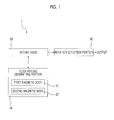
- Fig. 1 is a block diagram showing a rotary input device 1 of a first embodiment of the present invention.
- Fig. 2 is a perspective view showing the rotary input device 1 of the first embodiment.
- Fig. 3 is an exploded perspective view showing a rotary knob 20 and a click feeling generating portion 10 in the rotary input device 1 of the first embodiment.
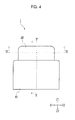
- Fig. 4 is a front view showing the rotary input device 1 of the first embodiment.
- Fig. 5 is a cross-sectional view taken along line V-V of Fig. 4 .
- Fig. 6 is a cross-sectional view taken along line VI-VI of Fig. 4 .
- the rotary input device 1 of the present embodiment is a mechanism by which an operator performing a rotation input operation of the rotary knob 20 obtains a click feeling. More specifically, the rotary input device is used for an input operation mechanism used in an input operation of electronic equipment or a vehicle. For example, different operation contents are input according to a rotation angle from a predetermined rotation position. As shown in Fig. 1 , a rotation detection portion 50 detecting a rotation angle of the rotary knob 20 is provided, and rotation angle information detected by the rotation detection portion 50 is output to electronic equipment or the like. Moreover, the rotation detection portion 50 detects not only the rotation angle but also a rotation direction or a rotational speed, for example.
- the rotary knob 20 is a molding member that includes a cylindrical operating portion 20b, and a shaft portion 20a that is concentrically formed with the operating portion 20b.
- the rotary knob 20 is accommodated in a case member 40 that rotatably supports the rotary knob 20, and the operating portion 20b protrudes from an opening of the case member 40.
- Z1 side of Fig. 2 is defined as an upper side
- Z2 side is defined as a lower side.
- the directions do not limit directions during use.
- the click feeling generating portion 10 is accommodated between the operating portion 20b of the rotary knob 20 and the shaft portion 20a.
- the click feeling generating portion 10 is disposed so that a first magnetic body 11 and a second magnetic body 21 are rotated relative to each other.
- the first magnetic body 11 is an annular member in which a plurality of outward protrusions 11a protruding toward the outside in a radial direction are disposed along a circumferential direction, and includes a magnet 12 that is magnetized to two poles of an upper pole and a lower pole, and a pair of yokes 13 and 14 that interposes the magnet 12 vertically.
- the magnet 12 is a permanent magnet molded in an annular shape, and in the magnet, opposing surfaces 12a and 12b facing each other are disposed vertically, and the magnet is magnetized to two poles of the upper pole and the lower pole including the opposing surfaces 12a and 12b.
- the pair of yokes 13 and 14 are magnetic materials formed in annular shapes, and in the present embodiment, a steel material is used. As shown in Fig. 3 , a plurality of outward protrusions 13a (16 outward protrusions in Fig. 3 ) which are outward protrusions 11a are formed on the outer circumference of the yoke 13. Similarly, a plurality of outward protrusions 14a (16 outward protrusions in Fig. 3 ) which are outward protrusions 11a are formed on the outer circumference of the yoke 14.
- the first magnetic body 11 is fitted to a fixing member 15 while interposing the magnet 12 so that the outward protrusions 13a and 14a of the yokes 13 and 14 overlap with one another vertically.
- the outward protrusions 13a and 14a of the yokes 13 and 14 protrude to the outside in the radial direction from the outer diameter of the magnet 12, and outer diameters of virtual circles of portions in which the outward protrusions 13a and 14a are not formed are approximately the same as the outer diameter of the magnet 12.
- the second magnetic body 21 of the present embodiment is an annular magnetic material that is concentrically disposed with the first magnetic body 11, and in the present embodiment, a steel material is used for the second magnetic body.
- a plurality of inward protrusions 21a are formed on the inner circumferential surface of the second magnetic body 21 along the circumferential direction.
- the length of each inward protrusion 21a is lengthened vertically (Z1-Z2 direction) to oppose each of the outward protrusion 13a of the yoke 13 and the outward protrusion 14a of the yoke 14 in the first magnetic body 11.
- the inward protrusion 21a and the outward protrusion 11a are disposed so that a rotation position at which the inward protrusion 21a and the outward protrusion 11a (13a and 14a) oppose each other becomes a defined position (refer to Figs. 6 and 7 ).
- the second magnetic body 21 is inserted to be fixed to the operating portion 20b of the rotary knob 20 so that the second magnetic body is integrally rotated with the rotary knob 20.
- the first magnetic body 11 is fitted to the fixing member 15 and fixed to the case member 40.
- the shaft portion 20a of the rotary knob 20 is inserted into the fixing member 15 via a rotary introduction member 45, and the first magnetic body 11 and the second magnetic body 21 are concentrically held in a non-contact state.
- a rotation angle sensor 52 detecting a rotation angle of the rotary knob 20 is disposed in the case member 40, and a rotation angle detection magnet 51 attached to the shaft portion 20a of the rotary knob 20 and the rotation angle sensor 52 configure a rotation detection portion 50.
- wires or the like for leading an output of the rotation angle sensor 52 to the outside of the case member 40 are omitted.
- Fig. 7 is an explanatory view showing the defined position of an initial state where the first magnetic body 11 and a second magnetic body 21 are relatively rotated.
- Fig. 8 is an explanatory view showing flows of magnetic flux of the first magnetic body 11 and the second magnetic body 21 in an A portion of Fig. 5 .
- Fig. 9 is an explanatory view showing magnetic attraction when the second magnetic body 21 is rotated from the defined position.
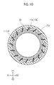
- Fig. 10 is an explanatory view showing the magnetic attraction when the second magnetic body 21 is further rotated from the defined position.
- the rotation position at which the inward protrusions 21a and the outward protrusion 11a oppose each other is defined as the defined position.
- a closed loop in which the magnetic flux passes through the outward protrusions 14a of the yoke 14, the inward protrusions 21a of the second magnetic body 21, and the outward protrusions 13a of the yoke 13 is formed. Accordingly, the magnetic attraction is generated between the first magnetic body 11 and the second magnetic body 21, and as shown in Fig.
- the first magnetic body and the second magnetic body are stable in the defined position at which the inward protrusions 21a and the outward protrusions 11a oppose each other. If the operating portion 20b of the rotary knob 20 is rotated from the defined position, operation feeling is generated by the magnetic attraction.
- the second magnetic body 21 is integrally rotated, and the inward protrusions 21a move from the rotation position at which the inward protrusions oppose the outward protrusions 11a of the first magnetic body 11.
- the magnetic flux from the magnet 12 flows to pass through the outward protrusions 11a and the inward protrusions 21a, as shown in Fig. 9 , the magnetic attraction is generated between the outward protrusions 11a and the inward protrusions 21a, and the magnetic attraction operates to suppress the rotation of the second magnetic body 21.
- the magnetic attraction is generated between the outward protrusions 11a, and the magnetic attraction operates to promote the rotation to the opposing position between the outward protrusions 11a and the inward protrusion 21a.
- the magnet 12 is a permanent magnet molded in an annular shape, and the opposing surfaces 12a and 12b facing each other are disposed vertically and are magnetized to two poles of the upper pole and the lower pole including the opposing surfaces 12a and 12b.
- the magnet 12 can be manufactured.
- the shape of the magnet 12 is a simple cylindrical annular shape and the structure of the magnet is a simple structure in which the magnetization direction is a constant direction, and thus, the magnet 12 is easily manufactured.
- the yokes 13 and 14 are formed as separate members, and thus, it is easy to form the outward protrusions 13a and 14a to the yokes 13 and 14.
- the first magnetic body 11 can be obtained only by interposing the upper surface and the lower surface of the magnet 12 with the yokes 13 and 14, compared to a structure in which a magnet having a complicated shape is integrally molded, the manufacturing is easier. Accordingly, since molding means for forming the magnet having a complicated shape is not required and complicated magnetizing means in which positions are slightly deviated and magnetized is not required, it is possible to decrease the cost of the click feeling generating portion 10.
- the click feeling of 16 times can be obtained when the rotary knob 20 is rotated once.
- this number is not limited. If the number of the outward protrusions 11a and the inward protrusions 21a or a pitch in the circumferential direction is changed, the frequency of the click feeling when the rotary knob is rotated once, the click feeling by the rotation position, or the like can be changed.
- Fig. 11 is an example of the outward protrusions 11a and the inward protrusions 21a having shapes different from Fig. 6 .
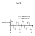
- Fig. 12 is an explanatory view in which rotary torque by the magnetic attraction in examples shown in Figs. 6 and 11 is compared. As shown in Fig. 12 , in the shapes of the outward protrusions 11a and the inward protrusions 21a of Figs. 6 and 11 , the rotary torques by the magnetic attraction are different from each other. Accordingly, the click feeling obtained by the rotary input device 1 is different.
- the rotary input device 1 of the present embodiment includes the first annular magnetic body 11 in which the plurality of outward protrusions 11a protruding toward the outside in the radial direction are disposed along the circumferential direction, the second annular magnetic body 21 in which the plurality of inward protrusions 21a formed to oppose the outward protrusions 11a of the first magnetic body 11 are disposed in the circumferential direction, and the rotary knob 20 that relatively rotates the first magnetic body 11 and the second magnetic body 21.
- the first magnetic body 11 includes the magnet 12 in which opposing surfaces 12a and 12b facing each other are vertically disposed and which is magnetized to two poles of the upper pole and the lower pole including the opposing surfaces 12a and 12b, the pair of yokes 13 and 14 that interposes the opposing surfaces 12a and 12b of the magnet 12 vertically, and the outward protrusions 11a (13a) and 11a (14a) formed on the pair of yokes 13 and 14.
- the upper surface and the lower surface (opposing surfaces 12a and 12b) of the magnet 12 vertically magnetized to two poles are interposed by the yokes 13 and 14, and the outward protrusions 13a and 14a are formed on the yokes 13 and 14, and thus, it is possible to effectively transmit the magnetic flux of the magnet 12 to opposing magnetic bodies. Therefore, the magnetic attraction is increased, and it is possible to improve the click feeling generated when the rotary knob 20 is operated by the change of the magnetic attraction. In addition, it is possible to securely stop the rotary knob 20 while the rotation position in which the inward protrusions 21a and the outward protrusions 11a oppose each other is defined as the defined position.
- the click feeling can be applied in a non-contact manner by the magnetic attraction, it is possible to decrease an operation sound.
- strong click feeling can be generated in a non-contact manner, and thus, deterioration due to the friction is decreased.
- the magnet 12 is vertically magnetized, a simple structure is obtained even when the magnet is an annular shape, and the manufacturing of the magnet is easy. In addition, since a single magnetization is sufficient with respect to the entire annular magnetic body, it is possible to decrease the cost.
- Fig. 13 is an exploded perspective view showing a rotary knob 30 and the click feeling generating portion 10 in a rotary input device 2 of a second embodiment.
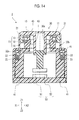
- Fig. 14 is a cross-sectional view of the rotary input device 2 which is cut similar to that in Fig. 5 .
- the rotary knob 30 and a case member 41 are different from those of the rotary input device 1 of the first embodiment.
- Other members are the same as in the first embodiment, and thus, the same reference numerals are used, and the descriptions thereof are omitted.
- the rotary knob 30 is a molding member that includes a cylindrical operating portion 30b, and a shaft portion 30a that is concentrically formed with the operating portion 30b.
- the rotary knob 30 is accommodated in the case member 41 that rotatably supports the rotary knob 30, and the operating portion 30b protrudes from an opening of the case member 41.
- a sliding portion 32 having a continuous concave shape 32a and a continuous convex shape 32b is formed on the lower surface of the rotary knob 30.
- a spherical body 33 and an elastic member 35 biasing the spherical body 33 are disposed between the case member 41 and the rotary knob 30.
- the spherical body 33, the elastic member 35 biasing the spherical body 33, and the sliding portion 32 including the continuous concave shape 32a and the continuous convex shape 32b formed on the rotary knob 30 configure the cam member.
- the rotation position at which the inward protrusions 21a and the outward protrusions 11a oppose each other becomes a maximum point of the concave shape 32a
- the rotation position corresponding to an intermediate position of the inward protrusion 21a and the outward protrusion 11a becomes a maximum point of the convex shape 32b when the inward protrusions 21a and the outward protrusions 11a are relatively rotated.
- the spherical body 33 relatively moves on the sliding portion 32 against an elastic force applied from the elastic member 35 according to the operation of the rotary knob 30.
- the cam member positions the rotary knob 30 with the rotation position at which the inward protrusions 21a and the outward protrusions 11a oppose each other as the defined position, and applies the operation reaction force to the rotary knob 30 when the rotary knob 30 is rotated from the defined position. Accordingly, it is possible to prevent the rotary knob 30 from not being stopped and being continuously vibrated, and it is possible to limit the continuous rotation. Moreover, since the click feeling is generated by the change of the magnetic attraction, the operation reaction force generated in the cam member may be decreased. If so, the friction force or the like applied to the cam member is decreased.
- the case member 41 that rotatably supports the rotary knob 30 is provided, and the cam member is provided between the case member 41 and the rotary knob 30.
- the cam member positions the rotary knob 30 with the rotation position at which the inward protrusions 21a and the outward protrusions 11a oppose each other as the defined position, and applies the operation reaction force to the rotary knob 30 when the rotary knob 30 is rotated from the defined position.
- the cam member since the cam member applies the operation reaction force to the rotary knob 30, it is possible to prevent the rotary knob 30 from not being stopped and being continuously vibrated, and it is possible to limit the continuous rotation.
- the click feeling is generated by the change of the magnetic attraction, the operation reaction force generated in the cam member may be decreased. Accordingly, since the friction force or the like applied to the cam member is decreased, wear is decreased and the lifespan can be lengthened.
- the cam member includes the spherical body 33, the elastic member 35 biasing the spherical body 33, and the sliding portion 32 including the continuous concave shape 32a and the continuous convex shape 32b formed on the rotary knob 30.
- the rotation position at which the inward protrusions 21a and the outward protrusions 11a oppose each other becomes the maximum point of the concave shape 32a
- the rotation position corresponding to the intermediate position of the inward protrusion 21a and the outward protrusion 11a becomes the maximum point of the convex shape 32b when the inward protrusions 21a and the outward protrusions 11a are relatively rotated.
- the spherical body 33 relatively moves on the sliding portion 32 against the elastic force applied from the elastic member 35 according to the operation of the rotary knob 30.
- the cam member can be configured by a simple structure, it is possible to decrease the cost.
- the click feeling is generated by the change of the magnetic attraction, it is possible to decrease the elastic force of the elastic member 35 generating the operation reaction force, and thus, the operation sound or the wear due to the sliding is not easily generated.
- Fig. 15 is a cross-sectional view showing a rotary input device 3 of a third embodiment.
- Fig. 16 is an explanatory view showing flows of the magnetic flux of a first magnetic body and a second magnetic body in a B portion of Fig. 15 .
- a second magnetic body 61 is different from that of the rotary input device 1 of the first embodiment.
- Other members are the same as in the first embodiment, and thus, the same reference numerals are used, and the descriptions thereof are omitted.
- the rotary input device 3 of the third embodiment includes the second magnetic body 61, a magnet 62, and a pair of yokes 63 and 64.
- the second magnetic body 61 is positioned vertically (Z1-Z2 direction) by a fixing member 25, and is inserted to be fixed to the operating portion 20b of the rotary knob 20.
- the first magnetic body 11 includes the magnet 12, the pair of yokes 13 and 14, and the outward protrusions 13a and 14a formed on the pair of yokes 13 and 14.
- the second magnetic body 61 includes an inward protrusion 61a.
- the inward protrusion 61a of the second magnetic body 61 is formed in two rows of upper and lower portions (inward protrusion 63a of yoke 63 and inward protrusion 64a of yoke 64) to oppose the outward protrusion 11a of the first magnetic body 11 (outward protrusion 13a of yoke 13 and outward protrusion 14a of yoke 14).
- the magnet 12 of the first magnetic body 11 and the magnet 62 of the second magnetic body 61 are positioned to be vertically inverted to each other and to be magnetized.
- the inward protrusion 61a and the outward protrusion 11a are disposed so that the rotation position at which the inward protrusion 61a and the outward protrusion 11a oppose each other becomes a defined position.
- the first magnetic body 11 and the second magnetic body 61 include the magnets 12 and 62, respectively, and the magnets 12 and 62 are disposed to attract each other. Accordingly, the magnetic attraction is generated between the first magnetic body 11 and the second magnetic body 61, and the first magnetic body and the second magnetic body are stable in the defined position at which the inward protrusion 21a and the outward protrusion 11a oppose each other. If the operating portion 20b of the rotary knob 20 is rotated from the defined position, the operation feeling is generated by the magnetic attraction.
- the first magnetic body 11 includes the magnet 12, the pair of yokes 13 and 14, and the outward protrusions 13a and 14a formed on the pair of yokes 13 and 14.
- the second magnetic body 61 includes the magnet 62, the pair of yokes 63 and 64, and the inward protrusions 63a and 64a formed on the pair of yokes 63 and 64.
- the magnet 12 of the first magnetic body 11 and the magnet 62 of the second magnetic body 61 are positioned to be vertically inverted to each other and to be magnetized.
- the inward protrusion 61a is formed in two rows of upper and lower portions (inward protrusion 63a of yoke 63 and inward protrusion 64a of yoke 64) to oppose the outward protrusion 11a of the first magnetic body 11 (outward protrusion 13a of yoke 13 and outward protrusion 14a of yoke 14), and the inward protrusion 61a and the outward protrusion 11a are disposed so that the rotation position at which the inward protrusion 61a and the outward protrusion 11a oppose each other becomes the defined position.
- the first magnetic body 11 and the second magnetic body 61 include the magnets 12 and 62, respectively, the magnets 12 and 62 are disposed to attract each other, and thus, it is possible to further increase the magnetic attraction. Accordingly, the magnetic attraction is increased, and an improved click feeling is easily obtained.
- Fig. 17 is a block diagram showing a rotary input device 4 of a fourth embodiment of the present invention.
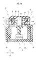
- Fig. 18 is a cross-sectional view showing the rotary input device 4 of the fourth embodiment.
- Fig. 19 is an explanatory view showing flows of magnetic flux of the first magnetic body 71 and the second magnetic body 21 in a C portion of Fig. 18 .
- the rotary input device 4 of the present embodiment includes a click feeling generating portion 70 and a click feeling controller 80 controlling the click feeling generating portion 70.
- the first magnetic body 71 includes a magnet 72 and a pair of yokes 73 and 74.
- the magnet 72 is an electromagnet that includes a core material 75 and a coil material 76 wound around the core material 75.
- Other members are the same as in the first embodiment, and thus, the same reference numerals are used, and the descriptions thereof are omitted.
- the click feeling generating portion 70 is disposed so that the first magnetic body 71 and the second magnetic body 21 are relatively rotated.
- the first magnetic body 71 includes outward protrusions 71a.
- the pair of yokes 73 and 74 is magnetic materials molded in an annular shape, and in the present embodiment, a steel material is used.
- the outward protrusion 71a of the first magnetic body 71 is formed to be divided into an outward protrusion 73a of the yoke 73 and an outward protrusion 74a of the yoke 74 of the upper portion and the lower portion.
- the core material 75 is a magnetic material formed in a cylindrical shape, and in the present embodiment, a steel material is used.
- the coil material 76 is wound around the outer circumference of the core material 75, and the coil material 76 is connected to the click feeling controller 80 by a wire (not shown). The coil material 76 is energized, and thus, the magnet 72 is excited, and a state where the magnet is magnetized to two poles of the upper portion and the lower portion is realized.
- the inward protrusion 21a of the second magnetic body 21 and the outward protrusion 71a of the first magnetic body 71 are disposed so that the rotation position at which the inward protrusion and the outward protrusion oppose each other becomes the defined position.
- the coil material 76 is energized, and thus, the magnetic attraction is generated between the first magnetic body 11 and the second magnetic body 21, and the first magnetic body and the second magnetic body are stable in the defined position at which the inward protrusions 21a and the outward protrusions 71a oppose each other. If the operating portion 20b of the rotary knob 20 is rotated from the defined position, operation feeling is generated by the magnetic attraction.
- the magnet 72 When the coil material 76 is not energized, the magnet 72 is not magnetized, and the magnetic attraction may not be generated. In this state, the click feeling is not generated even when the operating portion 20b of the rotary knob 20 is rotated, and it is possible to freely rotate the operating portion. Meanwhile, if the energized current is increased, strong magnetic attraction can be generated, and thus, it is possible to obtain a strong click feeling at a predetermined rotation angle according to the output of the rotation detection portion 50. Accordingly, it is possible to control the magnetic attraction, and thus, it is possible freely change the operation feeling.
- the core material 75 is formed in an annular shape, the coil material 76 is wound around the outer circumference.
- the coil material may be disposed to be distributed on a portion of the circumference. For example, according to the disposition of the outward protrusion 71a, the core material 75 and the coil material 76 are disposed on each position.
- the magnet 72 is an electromagnet that includes the core material 75 and the coil material 76 wound around the core material 75. According to this configuration, the magnet 72 is an electromagnet, and since it is possible to control the magnetic attraction by energizing the coil material 76, it is possible to freely change the operation feeling.
- the rotary knob is provided.
- a lever member which performs an arc-like operation may be attached to protrude to the side.
- the rotation center of the lever member may be coaxial with the rotation center of the rotary input device.
Landscapes
- Engineering & Computer Science (AREA)
- Physics & Mathematics (AREA)
- General Physics & Mathematics (AREA)
- Electromagnetism (AREA)
- General Engineering & Computer Science (AREA)
- Theoretical Computer Science (AREA)
- Automation & Control Theory (AREA)
- Power Engineering (AREA)
- Human Computer Interaction (AREA)
- Rotary Switch, Piano Key Switch, And Lever Switch (AREA)
- Mechanical Control Devices (AREA)
- Switches With Compound Operations (AREA)
Abstract

Description
- This application claims benefit of Japanese Patent Application No.
2014-016542 filed on January 31, 2014 - The present invention relates to a rotary input device by which a click feeling can be obtained.
- In recent years, a rotary input device by which a click feeling can be obtained is used in various industrial fields. For example, an information input device for rotation detection is disclosed in Japanese Unexamined Patent Application Publication No.
2003-280799 -
Fig. 24 is an exploded perspective view showing aninformation input device 100 disclosed in Japanese Unexamined Patent Application Publication No.2003-280799 Figs. 25A and 25B are perspective views showing a rotation detectionmagnetic body 152 ofFig. 24 ,Fig. 25A is a perspective view showing a positional relationship of ahall IC 136a with respect to a rotation detectionmagnetic body 152, andFig. 25B is a perspective view showing a portion of the rotation detectionmagnetic body 152 in an enlarged manner. - A
holding ring 164 and anoperation dial 154 are in a state of being rotatably held on abase 120, and if the holding ring and the operation dial are pressed, the holding ring and the operation dial are mounted to turn acentral tact switch 133 on. Moreover, in theoperation dial 154, if where the center portion of the operation dial is separated vertically and horizontally is pressed from the upper portion, the operation dial acts on thetact switch 132 and turns the tact switch on. - A click feeling generating
magnetic body 142 is configured of twoarc pieces annular holding portion 146 and are positioned on one circumference. Thearc pieces magnetic body 152 is integrally mounted to theoperation dial 154. An outer diameter of the rotation detectionmagnetic body 152 is larger than an outer diameter of the click feeling generatingmagnetic body 142, and similar to thearc pieces - A magnetic field defined by magnetic poles of the rotation detection
magnetic body 152 is detected byhall ICs operation dial 154 is rotated, strength of the detected magnetic field is changed, and thus, it is possible to detect a rotation amount and a rotation direction of theoperation dial 154. - The click feeling generating
magnetic body 142 is positioned inside the rotation detectionmagnetic body 152 and magnetically interacts with the rotation detectionmagnetic body 152, and if theoperation dial 154 is rotated, a click feeling is generated by the magnetic interaction. The rotation detectionmagnetic body 152 is formed in a doughnut shape, and as shown inFig. 25A , N poles and S poles are alternately disposed with a constant pitch when viewed from the above. As shown inFig. 25B , in a portion of the N pole when viewed from the above, the upper side becomes the N pole and the lower side becomes the S pole. Moreover, in a portion of the S pole when viewed from the above, the upper side becomes S pole and the lower side becomes N pole. This makes the rotation detectionmagnetic body 152 magnetize vertically for each range corresponding to the pitch. The click feeling generatingmagnetic body 142 is also magnetized by the similar method. - According to the magnetic interaction between the rotation detection
magnetic body 152 and the click feeling generatingmagnetic body 142, the click feeling is generated for each disposition angle pitch of the sets of the N poles and the S poles. Accordingly, for example, it is possible to remove unevenness or variation in the click feeling generated due to dimensional errors or wear of the rotation detectionmagnetic body 152 or the click feeling generatingmagnetic body 142. - However, in the rotation detection
magnetic body 152 and the click feeling generatingmagnetic body 142, the S poles and the N poles are alternately disposed in the circumferential direction, and for example, complicated magnetizing means in which the positions of the poles are slightly deviated and the poles are magnetized is required. Therefore, there is a problem that a cost according to the magnetization is increased. Moreover, when magnetic attraction is not strong, it is not possible to obtain an improved click feeling. - The present invention provides a rotary input device capable of decreasing a cost required for a structure to obtain a click feeling and obtaining an improved click feeling.
- According to an aspect of the present invention, there is provided a rotary input device including: a first annular magnetic body in which a plurality of outward protrusions protruding toward an outside in a radial direction are disposed along a circumferential direction; a second annular magnetic body in which a plurality of inward protrusions formed to oppose the outward protrusions of the first magnetic body are disposed along a circumferential direction; and a rotary knob configured to relatively rotate the first magnetic body and the second magnetic body, in which at least one of the first magnetic body and the second magnetic body includes a magnet in which opposing surfaces facing each other are vertically disposed and which is magnetized to two poles of an upper pole and a lower pole including the opposing surfaces, a pair of yokes that interposes the opposing surfaces of the magnet vertically, and the outward protrusion or the inward protrusion formed on the pair of yokes.
- According to this configuration, the upper surface and the lower surface of the magnet magnetized to two poles vertically are interposed by the yokes, the outward protrusions or the inward protrusions are formed on the yokes, and thus, it is possible to effectively transmit the magnetic flux of the magnet to opposing magnetic bodies. Therefore, the magnetic attraction is increased, and it is possible to improve the click feeling generated when the rotary knob is operated by the change of the magnetic attraction. Since the magnet is vertically magnetized, a simple structure is obtained even when the magnet is an annular shape, and the manufacturing of the magnet is easy. Accordingly, it is possible to provide the rotary input device in which the cost can be decreased and the click feeling is improved.
- In addition, in the rotary input device of the aspect, the rotary input device may include a case member configured to rotatably support the rotary knob, the cam member may be interposed between the case member and the rotary knob, and the cam member may position the rotary knob with a rotation position at which the inward protrusion and the outward protrusion oppose each other as a defined position, and may apply an operation reaction force to the rotary knob when the rotary knob is rotated from the defined position.
- According to this configuration, since the cam member applies the operation reaction force to the rotary knob, it is possible to prevent the rotary knob from not being stopped and being continuously vibrated, and it is possible to limit the continuous rotation. Moreover, since the click feeling is generated by the change of the magnetic attraction, it is possible to decrease the operation reaction force generated in the cam member. Accordingly, since the friction force or the like applied to the cam member is decreased, wear is decreased and the lifespan can be lengthened.
- Moreover, in the rotary input device of the aspect, the cam member may include a spherical body, an elastic body that biases the spherical body, and a sliding portion that is formed in a concave shape or a convex shape continuous to the rotary knob, the sliding portion may have a rotation position at which the inward protrusion and the outward protrusion oppose each other as a maximum point of the concave shape, a rotation position corresponding to an intermediate position between the inward protrusion and the outward protrusion may be set to a maximum point of the convex shape when the inward protrusion and the outward protrusion are relatively rotated, and the spherical body may move on the sliding portion against an elastic force applied from the elastic member according to the operation of the rotary knob.
- According to this configuration, since the cam member can be configured by a simple structure, it is possible to decrease the cost. In addition, since the click feeling is generated by the change of the magnetic attraction, it is possible to decrease the elastic force of the elastic member generating the operation reaction force, and thus, the operation sound or the wear due to the sliding is not easily generated.
- In addition, in the rotary input device of the aspect, each of the first magnetic body and the second magnetic body may include the magnet, the pair of yokes, and the outward protrusion or the inward protrusion formed on the pair of yokes, and the magnet of the first magnetic body and the magnet of the second magnetic body may be positioned to be vertically inverted to each other and to be magnetized.
- According to this configuration, the first magnetic body and the second magnetic body respectively include the magnets, the magnets are disposed to attract each other, and thus, it is possible to further increase the magnetic attraction.
- Moreover, in the rotary input device of the aspect, the magnet may be an electromagnet including a core material and a coil material wound around the core material.
- According to this configuration, the magnet is an electromagnet, and since it is possible to control the magnetic attraction by energizing the coil material, it is possible to freely change the operation feeling.
-
-
Fig. 1 is a block diagram showing a rotary input device of a first embodiment of the present invention; -
Fig. 2 is a perspective view showing the rotary input device of the first embodiment; -
Fig. 3 is an exploded perspective view showing a rotary knob and a click feeling generating portion in the rotary input device of the first embodiment; -
Fig. 4 is a front view showing the rotary input device of the first embodiment; -
Fig. 5 is a cross-sectional view taken along line V-V ofFig. 4 ; -
Fig. 6 is a cross-sectional view taken along line VI-VI ofFig. 4 ; -
Fig. 7 is an explanatory view showing a defined position of an initial state where a first magnetic body and a second magnetic body are relatively rotated; -
Fig. 8 is an explanatory view showing flows of magnetic flux of the first magnetic body and the second magnetic body in an A portion ofFig. 5 ; -
Fig. 9 is an explanatory view showing magnetic attraction when the second magnetic body is rotated from the defined position; -
Fig. 10 is an explanatory view showing magnetic attraction when the second magnetic body is further rotated from the defined position; -
Fig. 11 is an explanatory view showing an example in which a shape of an outward protrusion of the first magnetic body and a shape of an inward protrusion of the second magnetic body are different from each other; -
Fig. 12 is an explanatory view in which rotary torque by the magnetic attraction in the examples shown inFigs. 6 and11 is compared; -
Fig. 13 is an exploded perspective view showing a rotary knob and a click feeling generating portion in a rotary input device of a second embodiment of the present invention; -
Fig. 14 is a cross-sectional view showing a rotary input device of the second embodiment; -
Fig. 15 is a cross-sectional view showing a rotary input device of a third embodiment of the present invention; -
Fig. 16 is an explanatory view showing flows of magnetic flux of a first magnetic body and a second magnetic body in a B portion ofFig. 15 ; -
Fig. 17 is a block diagram showing a rotary input device of a fourth embodiment of the present invention; -
Fig. 18 is a cross-sectional view showing the rotary input device of the fourth embodiment; -
Fig. 19 is an explanatory view showing flows of magnetic flux of a first magnetic body and a second magnetic body in a C portion ofFig. 18 ; -
Fig. 20 is a cross-sectional view showing a first modification of the first embodiment; -
Fig. 21 is a cross-sectional view showing the first modification of the first embodiment, and is an explanatory view of a pushing-down operation; -
Fig. 22 is a cross-sectional view showing a second modification of the first embodiment; -
Fig. 23 is a cross-sectional view showing the second modification of the first embodiment, and is an explanatory view of a tilting operation; -
Fig. 24 is an exploded perspective view showing an information input device in the related art; and -
Figs. 25A and 25B are perspective views showing a rotation detection magnetic body ofFig. 24 ,Fig. 25A is a perspective view showing a positional relationship of a hall IC with respect to the rotation detection magnetic body, andFig. 25B is a perspective view showing a portion of the rotation detection magnetic body in an enlarged manner. - Hereinafter, embodiments of the present invention will be described in detail with reference to the drawings. Moreover, for convenience of understanding, scales in the drawings are appropriately changed.
-
Fig. 1 is a block diagram showing arotary input device 1 of a first embodiment of the present invention.Fig. 2 is a perspective view showing therotary input device 1 of the first embodiment.Fig. 3 is an exploded perspective view showing arotary knob 20 and a clickfeeling generating portion 10 in therotary input device 1 of the first embodiment.Fig. 4 is a front view showing therotary input device 1 of the first embodiment.Fig. 5 is a cross-sectional view taken along line V-V ofFig. 4 .Fig. 6 is a cross-sectional view taken along line VI-VI ofFig. 4 . - The
rotary input device 1 of the present embodiment is a mechanism by which an operator performing a rotation input operation of therotary knob 20 obtains a click feeling. More specifically, the rotary input device is used for an input operation mechanism used in an input operation of electronic equipment or a vehicle. For example, different operation contents are input according to a rotation angle from a predetermined rotation position. As shown inFig. 1 , arotation detection portion 50 detecting a rotation angle of therotary knob 20 is provided, and rotation angle information detected by therotation detection portion 50 is output to electronic equipment or the like. Moreover, therotation detection portion 50 detects not only the rotation angle but also a rotation direction or a rotational speed, for example. - The
rotary knob 20 is a molding member that includes acylindrical operating portion 20b, and ashaft portion 20a that is concentrically formed with the operatingportion 20b. Therotary knob 20 is accommodated in acase member 40 that rotatably supports therotary knob 20, and the operatingportion 20b protrudes from an opening of thecase member 40. In descriptions below, Z1 side ofFig. 2 is defined as an upper side, and Z2 side is defined as a lower side. However, the directions do not limit directions during use. - The click
feeling generating portion 10 is accommodated between the operatingportion 20b of therotary knob 20 and theshaft portion 20a. The clickfeeling generating portion 10 is disposed so that a firstmagnetic body 11 and a secondmagnetic body 21 are rotated relative to each other. - The first
magnetic body 11 is an annular member in which a plurality ofoutward protrusions 11a protruding toward the outside in a radial direction are disposed along a circumferential direction, and includes amagnet 12 that is magnetized to two poles of an upper pole and a lower pole, and a pair ofyokes magnet 12 vertically. - The
magnet 12 is a permanent magnet molded in an annular shape, and in the magnet, opposingsurfaces surfaces - The pair of
yokes Fig. 3 , a plurality ofoutward protrusions 13a (16 outward protrusions inFig. 3 ) which areoutward protrusions 11a are formed on the outer circumference of theyoke 13. Similarly, a plurality ofoutward protrusions 14a (16 outward protrusions inFig. 3 ) which areoutward protrusions 11a are formed on the outer circumference of theyoke 14. The firstmagnetic body 11 is fitted to a fixingmember 15 while interposing themagnet 12 so that theoutward protrusions yokes outward protrusions yokes magnet 12, and outer diameters of virtual circles of portions in which theoutward protrusions magnet 12. - The second
magnetic body 21 of the present embodiment is an annular magnetic material that is concentrically disposed with the firstmagnetic body 11, and in the present embodiment, a steel material is used for the second magnetic body. As shown inFig. 3 , a plurality ofinward protrusions 21a are formed on the inner circumferential surface of the secondmagnetic body 21 along the circumferential direction. As shown inFig. 5 , the length of eachinward protrusion 21a is lengthened vertically (Z1-Z2 direction) to oppose each of theoutward protrusion 13a of theyoke 13 and theoutward protrusion 14a of theyoke 14 in the firstmagnetic body 11. Moreover, theinward protrusion 21a and theoutward protrusion 11a (13a and 14a) are disposed so that a rotation position at which theinward protrusion 21a and theoutward protrusion 11a (13a and 14a) oppose each other becomes a defined position (refer toFigs. 6 and7 ). - In the present embodiment, the second
magnetic body 21 is inserted to be fixed to the operatingportion 20b of therotary knob 20 so that the second magnetic body is integrally rotated with therotary knob 20. On the other hand, as shown inFigs. 2 to 6 , the firstmagnetic body 11 is fitted to the fixingmember 15 and fixed to thecase member 40. Theshaft portion 20a of therotary knob 20 is inserted into the fixingmember 15 via arotary introduction member 45, and the firstmagnetic body 11 and the secondmagnetic body 21 are concentrically held in a non-contact state. - As shown in
Fig. 5 , arotation angle sensor 52 detecting a rotation angle of therotary knob 20 is disposed in thecase member 40, and a rotationangle detection magnet 51 attached to theshaft portion 20a of therotary knob 20 and therotation angle sensor 52 configure arotation detection portion 50. In addition, wires or the like for leading an output of therotation angle sensor 52 to the outside of thecase member 40 are omitted. - Next, an operation in which the
rotary input device 1 of the present embodiment applies operation feeling of therotary knob 20 will be described. -
Fig. 7 is an explanatory view showing the defined position of an initial state where the firstmagnetic body 11 and a secondmagnetic body 21 are relatively rotated.Fig. 8 is an explanatory view showing flows of magnetic flux of the firstmagnetic body 11 and the secondmagnetic body 21 in an A portion ofFig. 5 .Fig. 9 is an explanatory view showing magnetic attraction when the secondmagnetic body 21 is rotated from the defined position.Fig. 10 is an explanatory view showing the magnetic attraction when the secondmagnetic body 21 is further rotated from the defined position. - As shown in
Fig. 7 , the rotation position at which theinward protrusions 21a and theoutward protrusion 11a oppose each other is defined as the defined position. At this time, as shown inFig. 8 , if the magnetic flux of themagnet 12 flows from the N pole to the S pole, a closed loop in which the magnetic flux passes through theoutward protrusions 14a of theyoke 14, theinward protrusions 21a of the secondmagnetic body 21, and theoutward protrusions 13a of theyoke 13 is formed. Accordingly, the magnetic attraction is generated between the firstmagnetic body 11 and the secondmagnetic body 21, and as shown inFig. 7 , the first magnetic body and the second magnetic body are stable in the defined position at which theinward protrusions 21a and theoutward protrusions 11a oppose each other. If the operatingportion 20b of therotary knob 20 is rotated from the defined position, operation feeling is generated by the magnetic attraction. - For example, if the operating
portion 20b of therotary knob 20 is rotated in a counterclockwise direction, the secondmagnetic body 21 is integrally rotated, and theinward protrusions 21a move from the rotation position at which the inward protrusions oppose theoutward protrusions 11a of the firstmagnetic body 11. At this time, since the magnetic flux from themagnet 12 flows to pass through theoutward protrusions 11a and theinward protrusions 21a, as shown inFig. 9 , the magnetic attraction is generated between theoutward protrusions 11a and theinward protrusions 21a, and the magnetic attraction operates to suppress the rotation of the secondmagnetic body 21. - If the operating
portion 20b of therotary knob 20 is further rotated in a counterclockwise direction, since theoutward protrusions 11a and theinward protrusions 21a are disposed in plural along the circumferential direction, theinward protrusions 21a of the secondmagnetic body 21 are close to theoutward protrusions 11a adjacent to the defined position. As shown inFig. 10 , if the inward protrusions are away from the rotation position opposing theoutward protrusions 11a at the defined position and are close to the adjacentoutward protrusions 11a, the magnetic attraction is generated between theoutward protrusions 11a, and the magnetic attraction operates to promote the rotation to the opposing position between theoutward protrusions 11a and theinward protrusion 21a. - Since the magnetic attraction between the
outward protrusions 11a and theinward protrusions 21a repeatedly performs the operation of suppressing the rotation and the operation of promoting the rotation according to the rotation operation of therotary knob 20, the click feeling which is the operation feeling of therotary knob 20 is obtained. - In the present embodiment, the
magnet 12 is a permanent magnet molded in an annular shape, and the opposingsurfaces surfaces surfaces magnet 12 can be manufactured. The shape of themagnet 12 is a simple cylindrical annular shape and the structure of the magnet is a simple structure in which the magnetization direction is a constant direction, and thus, themagnet 12 is easily manufactured. - In addition, the
yokes outward protrusions yokes magnetic body 11 can be obtained only by interposing the upper surface and the lower surface of themagnet 12 with theyokes feeling generating portion 10. - In the
rotary input device 1 of the present embodiment, the click feeling of 16 times can be obtained when therotary knob 20 is rotated once. In addition, this number is not limited. If the number of theoutward protrusions 11a and theinward protrusions 21a or a pitch in the circumferential direction is changed, the frequency of the click feeling when the rotary knob is rotated once, the click feeling by the rotation position, or the like can be changed. - In addition, it is possible to change the click feeling according to shapes of the
outward protrusions 11a and theinward protrusions 21a.Fig. 11 is an example of theoutward protrusions 11a and theinward protrusions 21a having shapes different fromFig. 6 .Fig. 12 is an explanatory view in which rotary torque by the magnetic attraction in examples shown inFigs. 6 and11 is compared. As shown inFig. 12 , in the shapes of theoutward protrusions 11a and theinward protrusions 21a ofFigs. 6 and11 , the rotary torques by the magnetic attraction are different from each other. Accordingly, the click feeling obtained by therotary input device 1 is different. - Hereinafter, effects according to the present embodiment will be described.
- The
rotary input device 1 of the present embodiment includes the first annularmagnetic body 11 in which the plurality ofoutward protrusions 11a protruding toward the outside in the radial direction are disposed along the circumferential direction, the second annularmagnetic body 21 in which the plurality ofinward protrusions 21a formed to oppose theoutward protrusions 11a of the firstmagnetic body 11 are disposed in the circumferential direction, and therotary knob 20 that relatively rotates the firstmagnetic body 11 and the secondmagnetic body 21. The firstmagnetic body 11 includes themagnet 12 in which opposingsurfaces surfaces yokes surfaces magnet 12 vertically, and theoutward protrusions 11a (13a) and 11a (14a) formed on the pair ofyokes - According to this configuration, the upper surface and the lower surface (opposing
surfaces magnet 12 vertically magnetized to two poles are interposed by theyokes outward protrusions yokes magnet 12 to opposing magnetic bodies. Therefore, the magnetic attraction is increased, and it is possible to improve the click feeling generated when therotary knob 20 is operated by the change of the magnetic attraction. In addition, it is possible to securely stop therotary knob 20 while the rotation position in which theinward protrusions 21a and theoutward protrusions 11a oppose each other is defined as the defined position. Moreover, unlike a mechanism in which the click feeling is applied by a friction force of a sliding portion, since the click feeling can be applied in a non-contact manner by the magnetic attraction, it is possible to decrease an operation sound. In addition, strong click feeling can be generated in a non-contact manner, and thus, deterioration due to the friction is decreased. - Moreover, since the
magnet 12 is vertically magnetized, a simple structure is obtained even when the magnet is an annular shape, and the manufacturing of the magnet is easy. In addition, since a single magnetization is sufficient with respect to the entire annular magnetic body, it is possible to decrease the cost. - Accordingly, it is possible to provide the
rotary input device 1 in which the cost can be decreased and the click feeling is improved. -
Fig. 13 is an exploded perspective view showing arotary knob 30 and the clickfeeling generating portion 10 in arotary input device 2 of a second embodiment.Fig. 14 is a cross-sectional view of therotary input device 2 which is cut similar to that inFig. 5 . - In the
rotary input device 2 of the second embodiment, therotary knob 30 and acase member 41 are different from those of therotary input device 1 of the first embodiment. Other members are the same as in the first embodiment, and thus, the same reference numerals are used, and the descriptions thereof are omitted. - The
rotary knob 30 is a molding member that includes acylindrical operating portion 30b, and ashaft portion 30a that is concentrically formed with the operatingportion 30b. Therotary knob 30 is accommodated in thecase member 41 that rotatably supports therotary knob 30, and the operatingportion 30b protrudes from an opening of thecase member 41. - As shown in
Fig. 13 , in therotary input device 2 of the present embodiment, a slidingportion 32 having a continuousconcave shape 32a and a continuousconvex shape 32b is formed on the lower surface of therotary knob 30. Moreover, as shown inFig. 14 , aspherical body 33 and anelastic member 35 biasing thespherical body 33 are disposed between thecase member 41 and therotary knob 30. Thespherical body 33, theelastic member 35 biasing thespherical body 33, and the slidingportion 32 including the continuousconcave shape 32a and the continuousconvex shape 32b formed on therotary knob 30 configure the cam member. In the slidingportion 32, the rotation position at which theinward protrusions 21a and theoutward protrusions 11a oppose each other becomes a maximum point of theconcave shape 32a, and the rotation position corresponding to an intermediate position of theinward protrusion 21a and theoutward protrusion 11a becomes a maximum point of theconvex shape 32b when theinward protrusions 21a and theoutward protrusions 11a are relatively rotated. When viewed from therotary knob 30, thespherical body 33 relatively moves on the slidingportion 32 against an elastic force applied from theelastic member 35 according to the operation of therotary knob 30. - The cam member positions the
rotary knob 30 with the rotation position at which theinward protrusions 21a and theoutward protrusions 11a oppose each other as the defined position, and applies the operation reaction force to therotary knob 30 when therotary knob 30 is rotated from the defined position. Accordingly, it is possible to prevent therotary knob 30 from not being stopped and being continuously vibrated, and it is possible to limit the continuous rotation. Moreover, since the click feeling is generated by the change of the magnetic attraction, the operation reaction force generated in the cam member may be decreased. If so, the friction force or the like applied to the cam member is decreased. - Hereinafter, effects according to the present embodiment will be described.
- In the
rotary input device 2 of the present embodiment, thecase member 41 that rotatably supports therotary knob 30 is provided, and the cam member is provided between thecase member 41 and therotary knob 30. The cam member positions therotary knob 30 with the rotation position at which theinward protrusions 21a and theoutward protrusions 11a oppose each other as the defined position, and applies the operation reaction force to therotary knob 30 when therotary knob 30 is rotated from the defined position. According to this configuration, since the cam member applies the operation reaction force to therotary knob 30, it is possible to prevent therotary knob 30 from not being stopped and being continuously vibrated, and it is possible to limit the continuous rotation. Moreover, since the click feeling is generated by the change of the magnetic attraction, the operation reaction force generated in the cam member may be decreased. Accordingly, since the friction force or the like applied to the cam member is decreased, wear is decreased and the lifespan can be lengthened. - The cam member includes the
spherical body 33, theelastic member 35 biasing thespherical body 33, and the slidingportion 32 including the continuousconcave shape 32a and the continuousconvex shape 32b formed on therotary knob 30. In the slidingportion 32, the rotation position at which theinward protrusions 21a and theoutward protrusions 11a oppose each other becomes the maximum point of theconcave shape 32a, and the rotation position corresponding to the intermediate position of theinward protrusion 21a and theoutward protrusion 11a becomes the maximum point of theconvex shape 32b when theinward protrusions 21a and theoutward protrusions 11a are relatively rotated. Thespherical body 33 relatively moves on the slidingportion 32 against the elastic force applied from theelastic member 35 according to the operation of therotary knob 30. According to this configuration, since the cam member can be configured by a simple structure, it is possible to decrease the cost. In addition, since the click feeling is generated by the change of the magnetic attraction, it is possible to decrease the elastic force of theelastic member 35 generating the operation reaction force, and thus, the operation sound or the wear due to the sliding is not easily generated. -
Fig. 15 is a cross-sectional view showing arotary input device 3 of a third embodiment.Fig. 16 is an explanatory view showing flows of the magnetic flux of a first magnetic body and a second magnetic body in a B portion ofFig. 15 . - In the
rotary input device 3 of the third embodiment, a secondmagnetic body 61 is different from that of therotary input device 1 of the first embodiment. Other members are the same as in the first embodiment, and thus, the same reference numerals are used, and the descriptions thereof are omitted. - As shown in
Fig. 15 , therotary input device 3 of the third embodiment includes the secondmagnetic body 61, amagnet 62, and a pair ofyokes magnetic body 61 is positioned vertically (Z1-Z2 direction) by a fixingmember 25, and is inserted to be fixed to the operatingportion 20b of therotary knob 20. - As shown in
Fig. 16 , in therotary input device 3 of the present embodiment, the firstmagnetic body 11 includes themagnet 12, the pair ofyokes outward protrusions yokes Fig. 16 , the secondmagnetic body 61 includes aninward protrusion 61a. Theinward protrusion 61a of the secondmagnetic body 61 is formed in two rows of upper and lower portions (inward protrusion 63a ofyoke 63 andinward protrusion 64a of yoke 64) to oppose theoutward protrusion 11a of the first magnetic body 11 (outward protrusion 13a ofyoke 13 andoutward protrusion 14a of yoke 14). Themagnet 12 of the firstmagnetic body 11 and themagnet 62 of the secondmagnetic body 61 are positioned to be vertically inverted to each other and to be magnetized. Moreover, theinward protrusion 61a and theoutward protrusion 11a are disposed so that the rotation position at which theinward protrusion 61a and theoutward protrusion 11a oppose each other becomes a defined position. - As shown in
Fig. 16 , the firstmagnetic body 11 and the secondmagnetic body 61 include themagnets magnets magnetic body 11 and the secondmagnetic body 61, and the first magnetic body and the second magnetic body are stable in the defined position at which theinward protrusion 21a and theoutward protrusion 11a oppose each other. If the operatingportion 20b of therotary knob 20 is rotated from the defined position, the operation feeling is generated by the magnetic attraction. - Hereinafter, effects according to the present embodiment will be described.
- In the
rotary input device 3 of the present embodiment, the firstmagnetic body 11 includes themagnet 12, the pair ofyokes outward protrusions yokes magnetic body 61 includes themagnet 62, the pair ofyokes inward protrusions yokes magnet 12 of the firstmagnetic body 11 and themagnet 62 of the secondmagnetic body 61 are positioned to be vertically inverted to each other and to be magnetized. In addition, theinward protrusion 61a is formed in two rows of upper and lower portions (inward protrusion 63a ofyoke 63 andinward protrusion 64a of yoke 64) to oppose theoutward protrusion 11a of the first magnetic body 11 (outward protrusion 13a ofyoke 13 andoutward protrusion 14a of yoke 14), and theinward protrusion 61a and theoutward protrusion 11a are disposed so that the rotation position at which theinward protrusion 61a and theoutward protrusion 11a oppose each other becomes the defined position. - According to this configuration, the first
magnetic body 11 and the secondmagnetic body 61 include themagnets magnets -
Fig. 17 is a block diagram showing arotary input device 4 of a fourth embodiment of the present invention.Fig. 18 is a cross-sectional view showing therotary input device 4 of the fourth embodiment.Fig. 19 is an explanatory view showing flows of magnetic flux of the firstmagnetic body 71 and the secondmagnetic body 21 in a C portion ofFig. 18 . - As shown in
Fig. 17 , therotary input device 4 of the present embodiment includes a clickfeeling generating portion 70 and aclick feeling controller 80 controlling the clickfeeling generating portion 70. In addition, as shown inFig. 18 , the firstmagnetic body 71 includes amagnet 72 and a pair ofyokes magnet 72 is an electromagnet that includes acore material 75 and acoil material 76 wound around thecore material 75. Other members are the same as in the first embodiment, and thus, the same reference numerals are used, and the descriptions thereof are omitted. - The click
feeling generating portion 70 is disposed so that the firstmagnetic body 71 and the secondmagnetic body 21 are relatively rotated. In the present embodiment, the firstmagnetic body 71 includesoutward protrusions 71a. The pair ofyokes outward protrusion 71a of the firstmagnetic body 71 is formed to be divided into anoutward protrusion 73a of theyoke 73 and anoutward protrusion 74a of theyoke 74 of the upper portion and the lower portion. - The
core material 75 is a magnetic material formed in a cylindrical shape, and in the present embodiment, a steel material is used. Thecoil material 76 is wound around the outer circumference of thecore material 75, and thecoil material 76 is connected to theclick feeling controller 80 by a wire (not shown). Thecoil material 76 is energized, and thus, themagnet 72 is excited, and a state where the magnet is magnetized to two poles of the upper portion and the lower portion is realized. - The
inward protrusion 21a of the secondmagnetic body 21 and theoutward protrusion 71a of the firstmagnetic body 71 are disposed so that the rotation position at which the inward protrusion and the outward protrusion oppose each other becomes the defined position. At this time, thecoil material 76 is energized, and thus, the magnetic attraction is generated between the firstmagnetic body 11 and the secondmagnetic body 21, and the first magnetic body and the second magnetic body are stable in the defined position at which theinward protrusions 21a and theoutward protrusions 71a oppose each other. If the operatingportion 20b of therotary knob 20 is rotated from the defined position, operation feeling is generated by the magnetic attraction. - When the
coil material 76 is not energized, themagnet 72 is not magnetized, and the magnetic attraction may not be generated. In this state, the click feeling is not generated even when the operatingportion 20b of therotary knob 20 is rotated, and it is possible to freely rotate the operating portion. Meanwhile, if the energized current is increased, strong magnetic attraction can be generated, and thus, it is possible to obtain a strong click feeling at a predetermined rotation angle according to the output of therotation detection portion 50. Accordingly, it is possible to control the magnetic attraction, and thus, it is possible freely change the operation feeling. - Moreover, similar to the pair of
yokes core material 75 is formed in an annular shape, thecoil material 76 is wound around the outer circumference. However, the coil material may be disposed to be distributed on a portion of the circumference. For example, according to the disposition of theoutward protrusion 71a, thecore material 75 and thecoil material 76 are disposed on each position. - Hereinafter, effects according to the present embodiment will be described.
- In the
rotary input device 4 of the present embodiment, themagnet 72 is an electromagnet that includes thecore material 75 and thecoil material 76 wound around thecore material 75. According to this configuration, themagnet 72 is an electromagnet, and since it is possible to control the magnetic attraction by energizing thecoil material 76, it is possible to freely change the operation feeling. - As above, embodiments of the present invention are described in detail. However, the present invention is not limited to the above-described embodiments, and various modifications may be performed within a scope which does not depart from the gist. For example, the following modifications are possible, and the modifications are also included in the technical range of the present invention.
- (1) In the first embodiment, the second
magnetic body 21 is fixed to the operatingportion 20b of therotary knob 20, and the firstmagnetic body 11 is fixed to thecase member 40. However, the firstmagnetic body 11 may be fixed to be integrally rotated with theshaft portion 20a of therotary knob 20.Figs. 20 and21 are cross-sectional views showing a first modification of the first embodiment. In the present modification, it is possible to press therotary knob 20, and in order to obtain the click feeling according to the pushing-down operation, the shapes of the firstmagnetic body 11 and the secondmagnetic body 21 are studied. In addition, inFigs. 20 and21 , a mechanism for detecting the rotation and the pushing-down is omitted. - (2) In the first embodiment, the rotary shaft of the
rotary knob 20 is fixed and the rotation operation is performed. However, the embodiment may be modified so that a tilting operation is also performed.Figs. 22 and23 are cross-sectional views showing a second modification of the first embodiment. In the present modification, the tilting operation of therotary knob 20 is possible, and in order to obtain the click feeling according to the tilting operation, it is devised that the secondmagnetic body 21 is integrally tilted with therotary knob 20. In addition, inFigs. 22 and23 , a mechanism for detecting the tilting and the pushing-down is omitted. - (3) In the first and second embodiments, the
magnet 12 is used in the firstmagnetic body 11. However, the embodiments may be modified so that the magnet is used on the secondmagnetic body 21 side. - (4) In the first to fourth embodiments, the pair of yokes includes the vertical outward protrusions. However, the outward protrusion may be formed on only one of the upper yoke and the lower yoke. However, since the yoke in which the outward protrusion is not formed does not have a function generating the click feeling, the obtained click feeling is weak. In addition, if a magnet that is more strongly magnetized is used, it is possible to prevent the click feeling from being decreased.
- (5) In the first to fourth embodiment, if the number of the outward protrusions and the inward protrusions or the pitch in the circumference direction is changed, it is possible to change the frequency of the click feeling when being rotated once, the click feeling by the rotation position, or the like. Moreover, the number of the outward protrusions and the number of the inward protrusions may not be the same as each other. Since the strength of the click feeling generated at the rotation angle at which the outward protrusion and the inward protrusion oppose each other is dependent on the number of the opposing outward protrusions and inward protrusions, it is possible to change the click feeling by the rotation position.
- In addition, in the first to fourth embodiments, the rotary knob is provided. However, instead of the rotary knob or in a portion of the rotary knob, a lever member which performs an arc-like operation may be attached to protrude to the side. In this case, the rotation center of the lever member may be coaxial with the rotation center of the rotary input device. In the strength of the click feeling generated when the operation is performed via the lever member, stronger click feeling may be generated by disposing the rotary input devices on both sides while interposing the lever member.
- It should be understood by those skilled in the art that various modifications, combinations, sub-combinations and alterations may occur depending on design requirements and other factors insofar as they are within the scope of the appended claims of the equivalents thereof.
Claims (5)
- A rotary input device comprising:a first annular magnetic body (11, 71) in which a plurality of outward protrusions (11a, 71a) protruding toward an outside in a radial direction are disposed along a circumferential direction;a second annular magnetic body (21, 61) in which a plurality of inward protrusions (21a, 61a) formed to oppose the outward protrusions (11a, 71a) of the first magnetic body (11, 71) are disposed along a circumferential direction; anda rotary knob (20, 30) configured to relatively rotate the first magnetic body (11, 71) and the second magnetic body (21, 61),wherein at least one of the first magnetic body (11, 71) and the second magnetic body (21, 61) includes a magnet (21, 51, 62, 72) in which opposing surfaces (12a, 12b) facing each other are vertically disposed and which is magnetized to two poles of an upper pole and a lower pole including the opposing surfaces (12a, 12b), a pair of yokes (13, 14; 63, 64; 73, 74) that interposes the opposing surfaces of the magnet vertically, and the outward protrusion or the inward protrusion formed on the pair of yokes (13, 14; 63, 64; 73, 74).
- The rotary input device according to claim 1, further comprising:a case member (40, 41) configured to rotatably support the rotary knob (20, 30),wherein a cam member is interposed between the case member (40, 41) and the rotary knob (20, 30), andwherein the cam member positions the rotary knob (20, 30) with a rotation position at which the inward protrusion and the outward protrusion oppose each other as a defined position, and applies an operation reaction force to the rotary knob when the rotary knob (20, 30) is rotated from the defined position.
- The rotary input device according to claim 2,
wherein the cam member includes a spherical body (33), an elastic body (35) that biases the spherical body (33), and a sliding portion (32) that is formed in a concave shape (32a) or a convex shape (32b) continuous to the rotary knob (20, 30),
wherein the sliding portion (32) has a rotation position at which the inward protrusion and the outward protrusion oppose each other as a maximum point of the concave shape (32a),
wherein a rotation position corresponding to an intermediate position between the inward protrusion and the outward protrusion is set to a maximum point of the convex shape (32b) when the inward protrusion and the outward protrusion are relatively rotated, and
wherein the spherical body (33) moves on the sliding portion (32) against an elastic force applied from the elastic member (35) according to the operation of the rotary knob (30). - The rotary input device according to any one of claims 1 to 3,
wherein each of the first magnetic body (11, 71) and the second magnetic body (21, 61) includes the magnet (21, 51, 62, 72), the pair of yokes (13, 14; 63, 64; 73, 74), and the outward protrusion or the inward protrusion formed on the pair of yokes, and
wherein the magnet of the first magnetic body (11, 71) and the magnet of the second magnetic body (21, 61) are positioned to be vertically inverted to each other and to be magnetized. - The rotary input device according to any one of claims 1 to 4,
wherein the magnet is an electromagnet including a core material (75) and a coil material (76) wound around the core material (75).
Applications Claiming Priority (1)
| Application Number | Priority Date | Filing Date | Title |
|---|---|---|---|
| JP2014016542A JP6226425B2 (en) | 2014-01-31 | 2014-01-31 | Rotation input device |
Publications (2)
| Publication Number | Publication Date |
|---|---|
| EP2902878A1 true EP2902878A1 (en) | 2015-08-05 |
| EP2902878B1 EP2902878B1 (en) | 2018-02-07 |
Family
ID=52272862
Family Applications (1)
| Application Number | Title | Priority Date | Filing Date |
|---|---|---|---|
| EP14198785.9A Active EP2902878B1 (en) | 2014-01-31 | 2014-12-18 | Rotary input device |
Country Status (4)
| Country | Link |
|---|---|
| US (1) | US9437357B2 (en) |
| EP (1) | EP2902878B1 (en) |
| JP (1) | JP6226425B2 (en) |
| CN (1) | CN104820463A (en) |
Cited By (6)
| Publication number | Priority date | Publication date | Assignee | Title |
|---|---|---|---|---|
| EP3318951A3 (en) * | 2016-09-21 | 2018-06-27 | Alps Electric Co., Ltd. | Rotational input device |
| FR3089314A1 (en) * | 2018-11-29 | 2020-06-05 | Moving Magnet Technologies | ADJUSTABLE EFFORT DEVICE |
| CN111339704A (en) * | 2020-02-28 | 2020-06-26 | 四川电力设计咨询有限责任公司 | Strength design method for misalignment node of power transmission tower |
| FR3102433A1 (en) * | 2019-10-23 | 2021-04-30 | Dav | Motor vehicle interface and control unit |
| WO2021099136A1 (en) * | 2019-11-18 | 2021-05-27 | Marquardt Gmbh | Actuator, in particular for a motor vehicle |
| CN115698896A (en) * | 2020-03-31 | 2023-02-03 | 动磁科技公司 | Passive haptic device |
Families Citing this family (58)
| Publication number | Priority date | Publication date | Assignee | Title |
|---|---|---|---|---|
| US9753436B2 (en) * | 2013-06-11 | 2017-09-05 | Apple Inc. | Rotary input mechanism for an electronic device |
| CN109634447B (en) | 2013-08-09 | 2022-04-19 | 苹果公司 | Tactile switch for electronic devices |
| JP2015145816A (en) * | 2014-02-03 | 2015-08-13 | アイシン精機株式会社 | displacement sensor |
| WO2015122885A1 (en) | 2014-02-12 | 2015-08-20 | Bodhi Technology Ventures Llc | Rejection of false turns of rotary inputs for electronic devices |
| US10190891B1 (en) | 2014-07-16 | 2019-01-29 | Apple Inc. | Optical encoder for detecting rotational and axial movement |
| US10599101B2 (en) | 2014-09-02 | 2020-03-24 | Apple Inc. | Wearable electronic device |
| JP6534071B2 (en) * | 2014-11-19 | 2019-06-26 | パナソニックIpマネジメント株式会社 | Input / output control device |
| US10528073B2 (en) * | 2015-03-04 | 2020-01-07 | Snap-On Incorporated | Rotatable control device with axial translation |
| KR101940943B1 (en) | 2015-03-05 | 2019-01-21 | 애플 인크. | Optical encoder with direction dependent optical properties |
| WO2016144919A1 (en) | 2015-03-08 | 2016-09-15 | Apple Inc. | Compressible seal for rotatable and translatable input mechanisms |
| US10018966B2 (en) | 2015-04-24 | 2018-07-10 | Apple Inc. | Cover member for an input mechanism of an electronic device |
| US9977456B2 (en) * | 2015-04-29 | 2018-05-22 | Advanced Input Devices, Inc. | Magnetic detenting configuration for custom encoder |
| CN105138068B (en) * | 2015-08-31 | 2017-03-01 | 广东美的厨房电器制造有限公司 | Knob structure, the anglec of rotation determine method, device and household electrical appliance |
| US9891651B2 (en) | 2016-02-27 | 2018-02-13 | Apple Inc. | Rotatable input mechanism having adjustable output |
| US9778760B1 (en) * | 2016-03-09 | 2017-10-03 | Microsoft Technology Licensing, Llc | Magnetic detent for input controls |
| JP6665670B2 (en) * | 2016-05-10 | 2020-03-13 | 富士通コネクテッドテクノロジーズ株式会社 | Input device |
| US10551798B1 (en) | 2016-05-17 | 2020-02-04 | Apple Inc. | Rotatable crown for an electronic device |
| US10061399B2 (en) | 2016-07-15 | 2018-08-28 | Apple Inc. | Capacitive gap sensor ring for an input device |
| US10019097B2 (en) | 2016-07-25 | 2018-07-10 | Apple Inc. | Force-detecting input structure |
| JP6767217B2 (en) * | 2016-09-16 | 2020-10-14 | アルプスアルパイン株式会社 | Input device |
| CN108205380A (en) * | 2016-12-16 | 2018-06-26 | 高璁锦 | Magnetic fixed-frame roller device of roller type mouse |
| CN110114736B (en) * | 2016-12-21 | 2021-06-01 | 阿尔卑斯阿尔派株式会社 | Operating device |
| US10664074B2 (en) | 2017-06-19 | 2020-05-26 | Apple Inc. | Contact-sensitive crown for an electronic watch |
| US10962935B1 (en) | 2017-07-18 | 2021-03-30 | Apple Inc. | Tri-axis force sensor |
| JP6957276B2 (en) * | 2017-09-06 | 2021-11-02 | キヤノン株式会社 | Electronics |
| EP3715999B1 (en) * | 2017-11-24 | 2023-01-04 | Alps Alpine Co., Ltd. | Operating device |
| US10395863B2 (en) | 2017-11-28 | 2019-08-27 | Denso International America, Inc. | Magnetic rotary dial |
| DE102017128820A1 (en) * | 2017-12-05 | 2019-06-06 | Vorwerk & Co. Interholding Gmbh | Actuation device with magnets |
| US20190206642A1 (en) * | 2018-01-02 | 2019-07-04 | Getac Technology Corporation | Information capturing device |
| JP7005397B2 (en) * | 2018-03-14 | 2022-01-21 | キヤノン株式会社 | Rotation control unit and electronic equipment |
| CN108400046A (en) * | 2018-05-10 | 2018-08-14 | 黄福生 | A kind of magnetic suspension knob and automobile gear shift switch |
| US11360440B2 (en) | 2018-06-25 | 2022-06-14 | Apple Inc. | Crown for an electronic watch |
| US11422643B2 (en) | 2018-06-27 | 2022-08-23 | Logitech Europe S.A. | Adaptive scroll wheel |
| US11934595B2 (en) * | 2018-06-27 | 2024-03-19 | Logitech Europe S.A. | Variable response rotary input control for a computer peripheral device |
| JP2020008990A (en) * | 2018-07-04 | 2020-01-16 | 富士通コンポーネント株式会社 | Switch system |
| US11561515B2 (en) | 2018-08-02 | 2023-01-24 | Apple Inc. | Crown for an electronic watch |
| US11181863B2 (en) | 2018-08-24 | 2021-11-23 | Apple Inc. | Conductive cap for watch crown |
| US12259690B2 (en) | 2018-08-24 | 2025-03-25 | Apple Inc. | Watch crown having a conductive surface |
| CN209560398U (en) | 2018-08-24 | 2019-10-29 | 苹果公司 | digital watch |
| CN209625187U (en) | 2018-08-30 | 2019-11-12 | 苹果公司 | Electronic Watches and Electronic Devices |
| US11194298B2 (en) | 2018-08-30 | 2021-12-07 | Apple Inc. | Crown assembly for an electronic watch |
| JP7065196B2 (en) | 2018-10-25 | 2022-05-11 | 富士フイルム株式会社 | Lens barrel |
| JP7219615B2 (en) * | 2018-12-28 | 2023-02-08 | 株式会社ジャパンディスプレイ | Operation support device |
| US11194299B1 (en) | 2019-02-12 | 2021-12-07 | Apple Inc. | Variable frictional feedback device for a digital crown of an electronic watch |
| US11450462B2 (en) * | 2019-02-18 | 2022-09-20 | Canon Kabushiki Kaisha | Operation device that produces clicking sensation, and electronic apparatus |
| FR3099833B1 (en) * | 2019-08-07 | 2024-09-13 | Moving Magnet Tech | Passive haptic interface |
| KR102697977B1 (en) * | 2019-09-09 | 2024-08-22 | 에스엘 주식회사 | Transmission for vehicle |
| CN110989765A (en) * | 2019-12-19 | 2020-04-10 | 业成科技(成都)有限公司 | Hybrid knob |
| JP6896178B1 (en) | 2019-12-26 | 2021-06-30 | 三菱電機株式会社 | Tactile presentation device, tactile presentation knob |
| US11550268B2 (en) | 2020-06-02 | 2023-01-10 | Apple Inc. | Switch module for electronic crown assembly |
| TR202017938A1 (en) * | 2020-11-10 | 2022-05-23 | Ali Ak | ROTARY SWITCH WITH AN INTEGRATED TORQUE HANDLE |
| CN112635226B (en) * | 2020-12-10 | 2022-11-22 | 歌尔科技有限公司 | Rotary key and wearable device with same |
| US11747919B1 (en) | 2021-05-14 | 2023-09-05 | Apple Inc. | Multi-input for rotating and translating crown modules |
| US12092996B2 (en) | 2021-07-16 | 2024-09-17 | Apple Inc. | Laser-based rotation sensor for a crown of an electronic watch |
| KR102376160B1 (en) | 2021-10-29 | 2022-03-21 | 주식회사 서연이화 | Knob structure of user-interface gadget |
| US12189347B2 (en) | 2022-06-14 | 2025-01-07 | Apple Inc. | Rotation sensor for a crown of an electronic watch |
| US12596334B2 (en) | 2023-02-07 | 2026-04-07 | Apple Inc. | Crown for an electronic watch |
| EP4636798A1 (en) * | 2024-04-15 | 2025-10-22 | Black & Decker, Inc. | An actuator for actuating a switch of a powered device that is magnectically holdable in a plurality of positions |
Citations (3)
| Publication number | Priority date | Publication date | Assignee | Title |
|---|---|---|---|---|
| US6182370B1 (en) * | 1996-07-05 | 2001-02-06 | Euchner Gmbh And Co. | Manually operated angle pickup |
| JP2003280799A (en) | 2002-03-25 | 2003-10-02 | Sony Corp | Information input device and electronic equipment using it |
| US20080197004A1 (en) * | 2007-02-20 | 2008-08-21 | Kabushiki Kaisha Tokai Rika Denki Seisakusho | Control switch apparatus |
Family Cites Families (20)
| Publication number | Priority date | Publication date | Assignee | Title |
|---|---|---|---|---|
| US3934216A (en) * | 1974-12-11 | 1976-01-20 | Clarostat Mfg. Co., Inc. | Magnetic detent device |
| DE19651315A1 (en) * | 1996-12-11 | 1998-06-18 | A B Elektronik Gmbh | Rotary indexing switch with latched dialling settings e.g. for dialling motor vehicle on-board computer |
| JPH1141897A (en) * | 1997-07-24 | 1999-02-12 | Alps Electric Co Ltd | Motor with rotation speed detection means |
| JP3537294B2 (en) * | 1997-08-01 | 2004-06-14 | アルプス電気株式会社 | Motor having rotation speed detecting means |
| JP3543930B2 (en) * | 1998-11-18 | 2004-07-21 | アルプス電気株式会社 | Brushless motor and magnetic recording / reproducing device using this brushless motor |
| US6759933B2 (en) * | 2000-06-30 | 2004-07-06 | Ab Eletronik Gmbh | Position selector device |
| JP4057862B2 (en) * | 2002-08-27 | 2008-03-05 | アルプス電気株式会社 | Combined operation type input device |
| JP4359478B2 (en) * | 2003-10-14 | 2009-11-04 | アルプス電気株式会社 | Joystick type switch device |
| EP1524680B1 (en) * | 2003-10-14 | 2007-12-19 | Alps Electric Co., Ltd. | Joystick input device |
| JP4383306B2 (en) * | 2004-10-05 | 2009-12-16 | アルプス電気株式会社 | Illumination device |
| JP2006244885A (en) * | 2005-03-04 | 2006-09-14 | Shin Caterpillar Mitsubishi Ltd | Dial operating tool |
| JP4100409B2 (en) * | 2005-04-01 | 2008-06-11 | オムロン株式会社 | Operation input device and electronic apparatus using the same |
| JP4709081B2 (en) * | 2005-07-27 | 2011-06-22 | 株式会社東海理化電機製作所 | Switch device |
| US7767916B2 (en) * | 2006-06-30 | 2010-08-03 | Kabushiki Kaisha Tokai Rika Denki Seisakusho | Switch device |
| US7934335B2 (en) * | 2006-10-20 | 2011-05-03 | Leupold & Stevens, Inc. | Pop-up adjustment cap system for sighting device |
| JP2008201276A (en) * | 2007-02-20 | 2008-09-04 | Tokai Rika Co Ltd | Operation switch device |
| JP4990811B2 (en) * | 2008-02-08 | 2012-08-01 | ホシデン株式会社 | Rotation switch |
| CN101673125B (en) * | 2008-09-11 | 2012-07-04 | 宝元数控精密股份有限公司 | Magnetic handwheel |
| JP5098928B2 (en) * | 2008-09-26 | 2012-12-12 | オムロン株式会社 | INPUT DEVICE AND ELECTRONIC DEVICE USING THE SAME |
| JP5792089B2 (en) * | 2012-02-08 | 2015-10-07 | アルプス電気株式会社 | Electromagnetic brake device and haptic rotation input device using the same |
-
2014
- 2014-01-31 JP JP2014016542A patent/JP6226425B2/en active Active
- 2014-12-12 US US14/569,400 patent/US9437357B2/en active Active
- 2014-12-18 EP EP14198785.9A patent/EP2902878B1/en active Active
-
2015
- 2015-01-28 CN CN201510043529.6A patent/CN104820463A/en active Pending
Patent Citations (3)
| Publication number | Priority date | Publication date | Assignee | Title |
|---|---|---|---|---|
| US6182370B1 (en) * | 1996-07-05 | 2001-02-06 | Euchner Gmbh And Co. | Manually operated angle pickup |
| JP2003280799A (en) | 2002-03-25 | 2003-10-02 | Sony Corp | Information input device and electronic equipment using it |
| US20080197004A1 (en) * | 2007-02-20 | 2008-08-21 | Kabushiki Kaisha Tokai Rika Denki Seisakusho | Control switch apparatus |
Cited By (9)
| Publication number | Priority date | Publication date | Assignee | Title |
|---|---|---|---|---|
| EP3318951A3 (en) * | 2016-09-21 | 2018-06-27 | Alps Electric Co., Ltd. | Rotational input device |
| FR3089314A1 (en) * | 2018-11-29 | 2020-06-05 | Moving Magnet Technologies | ADJUSTABLE EFFORT DEVICE |
| WO2020109744A3 (en) * | 2018-11-29 | 2020-07-23 | Moving Magnet Technologies | Adjustable force device |
| CN113168204A (en) * | 2018-11-29 | 2021-07-23 | 移动磁体技术公司 | Force adjustable device |
| FR3102433A1 (en) * | 2019-10-23 | 2021-04-30 | Dav | Motor vehicle interface and control unit |
| WO2021099136A1 (en) * | 2019-11-18 | 2021-05-27 | Marquardt Gmbh | Actuator, in particular for a motor vehicle |
| CN111339704A (en) * | 2020-02-28 | 2020-06-26 | 四川电力设计咨询有限责任公司 | Strength design method for misalignment node of power transmission tower |
| CN111339704B (en) * | 2020-02-28 | 2023-07-18 | 四川电力设计咨询有限责任公司 | Strength design method for staggered nodes of transmission towers |
| CN115698896A (en) * | 2020-03-31 | 2023-02-03 | 动磁科技公司 | Passive haptic device |
Also Published As
| Publication number | Publication date |
|---|---|
| EP2902878B1 (en) | 2018-02-07 |
| CN104820463A (en) | 2015-08-05 |
| JP2015144048A (en) | 2015-08-06 |
| US9437357B2 (en) | 2016-09-06 |
| JP6226425B2 (en) | 2017-11-08 |
| US20150221426A1 (en) | 2015-08-06 |
Similar Documents
| Publication | Publication Date | Title |
|---|---|---|
| US9437357B2 (en) | Rotary input device | |
| WO2014194140A3 (en) | Electromagnetic opposing field actuators | |
| US10209096B2 (en) | Rotation detecting device | |
| US10260873B2 (en) | Surveying apparatus with positioning device | |
| JP2011513979A5 (en) | ||
| CN101424544A (en) | Position sensor utilizing a linear hall-effect sensor | |
| JP2008237004A5 (en) | ||
| EP2703784A2 (en) | Rotation detecting device | |
| EP3023745A1 (en) | Rotation angle detecting device | |
| JP2011080788A (en) | Rotation angle detection device | |
| JP2017117324A (en) | Joystick | |
| US20130038145A1 (en) | Drive device, and movement mechanism using drive device | |
| US20070040803A1 (en) | Method of joining a sintered magnet to a pivot arm | |
| JP2017059618A (en) | Magnetizing apparatus and method for magnetic encoder | |
| US20090278638A1 (en) | Control Device Comprising Means for Indexing the Position of the Control Means | |
| JP6436457B2 (en) | Rotation input device | |
| JP7428996B1 (en) | Electromagnet and magnetic field application system | |
| KR101672134B1 (en) | Displacement providing device for displace article using permanent magnet | |
| JP6442253B2 (en) | Magnetic encoder magnetizer | |
| JP2008108763A (en) | Magnetizing apparatus and magnetizing method | |
| JP2023001514A (en) | rotary encoder | |
| WO2008056756A1 (en) | Diode magnetic encoder, and its manufacturing method | |
| JP7026569B2 (en) | Force-imparting operation device | |
| KR102101296B1 (en) | Magnetization apparatus | |
| JP2019191073A (en) | Magnetic rotation angle detector |
Legal Events
| Date | Code | Title | Description |
|---|---|---|---|
| PUAI | Public reference made under article 153(3) epc to a published international application that has entered the european phase |
Free format text: ORIGINAL CODE: 0009012 |
|
| 17P | Request for examination filed |
Effective date: 20141218 |
|
| AK | Designated contracting states |
Kind code of ref document: A1 Designated state(s): AL AT BE BG CH CY CZ DE DK EE ES FI FR GB GR HR HU IE IS IT LI LT LU LV MC MK MT NL NO PL PT RO RS SE SI SK SM TR |
|
| AX | Request for extension of the european patent |
Extension state: BA ME |
|
| 17P | Request for examination filed |
Effective date: 20160119 |
|
| RBV | Designated contracting states (corrected) |
Designated state(s): AL AT BE BG CH CY CZ DE DK EE ES FI FR GB GR HR HU IE IS IT LI LT LU LV MC MK MT NL NO PL PT RO RS SE SI SK SM TR |
|
| 17Q | First examination report despatched |
Effective date: 20160712 |
|
| REG | Reference to a national code |
Ref country code: DE Ref legal event code: R079 Ref document number: 602014020745 Country of ref document: DE Free format text: PREVIOUS MAIN CLASS: G06F0003010000 Ipc: G06F0003036200 |
|
| GRAP | Despatch of communication of intention to grant a patent |
Free format text: ORIGINAL CODE: EPIDOSNIGR1 |
|
| RIC1 | Information provided on ipc code assigned before grant |
Ipc: H01H 19/11 20060101ALI20170621BHEP Ipc: H01H 5/02 20060101ALI20170621BHEP Ipc: G05G 5/03 20080401ALI20170621BHEP Ipc: H01H 25/06 20060101ALI20170621BHEP Ipc: H03K 17/97 20060101ALI20170621BHEP Ipc: G01B 7/00 20060101ALI20170621BHEP Ipc: G01B 7/30 20060101ALI20170621BHEP Ipc: G05G 1/08 20060101ALI20170621BHEP Ipc: G06F 3/0362 20130101AFI20170621BHEP Ipc: H01H 3/50 20060101ALI20170621BHEP |
|
| INTG | Intention to grant announced |
Effective date: 20170721 |
|
| GRAS | Grant fee paid |
Free format text: ORIGINAL CODE: EPIDOSNIGR3 |
|
| GRAA | (expected) grant |
Free format text: ORIGINAL CODE: 0009210 |
|
| AK | Designated contracting states |
Kind code of ref document: B1 Designated state(s): AL AT BE BG CH CY CZ DE DK EE ES FI FR GB GR HR HU IE IS IT LI LT LU LV MC MK MT NL NO PL PT RO RS SE SI SK SM TR |
|
| REG | Reference to a national code |
Ref country code: GB Ref legal event code: FG4D |
|
| REG | Reference to a national code |
Ref country code: AT Ref legal event code: REF Ref document number: 969033 Country of ref document: AT Kind code of ref document: T Effective date: 20180215 Ref country code: CH Ref legal event code: EP |
|
| REG | Reference to a national code |
Ref country code: IE Ref legal event code: FG4D |
|
| REG | Reference to a national code |
Ref country code: DE Ref legal event code: R096 Ref document number: 602014020745 Country of ref document: DE |
|
| REG | Reference to a national code |
Ref country code: NL Ref legal event code: MP Effective date: 20180207 |
|
| REG | Reference to a national code |
Ref country code: AT Ref legal event code: MK05 Ref document number: 969033 Country of ref document: AT Kind code of ref document: T Effective date: 20180207 |
|
| PG25 | Lapsed in a contracting state [announced via postgrant information from national office to epo] |
Ref country code: ES Free format text: LAPSE BECAUSE OF FAILURE TO SUBMIT A TRANSLATION OF THE DESCRIPTION OR TO PAY THE FEE WITHIN THE PRESCRIBED TIME-LIMIT Effective date: 20180207 Ref country code: NL Free format text: LAPSE BECAUSE OF FAILURE TO SUBMIT A TRANSLATION OF THE DESCRIPTION OR TO PAY THE FEE WITHIN THE PRESCRIBED TIME-LIMIT Effective date: 20180207 Ref country code: CY Free format text: LAPSE BECAUSE OF FAILURE TO SUBMIT A TRANSLATION OF THE DESCRIPTION OR TO PAY THE FEE WITHIN THE PRESCRIBED TIME-LIMIT Effective date: 20180207 Ref country code: FI Free format text: LAPSE BECAUSE OF FAILURE TO SUBMIT A TRANSLATION OF THE DESCRIPTION OR TO PAY THE FEE WITHIN THE PRESCRIBED TIME-LIMIT Effective date: 20180207 Ref country code: LT Free format text: LAPSE BECAUSE OF FAILURE TO SUBMIT A TRANSLATION OF THE DESCRIPTION OR TO PAY THE FEE WITHIN THE PRESCRIBED TIME-LIMIT Effective date: 20180207 Ref country code: HR Free format text: LAPSE BECAUSE OF FAILURE TO SUBMIT A TRANSLATION OF THE DESCRIPTION OR TO PAY THE FEE WITHIN THE PRESCRIBED TIME-LIMIT Effective date: 20180207 Ref country code: NO Free format text: LAPSE BECAUSE OF FAILURE TO SUBMIT A TRANSLATION OF THE DESCRIPTION OR TO PAY THE FEE WITHIN THE PRESCRIBED TIME-LIMIT Effective date: 20180507 |
|
| PG25 | Lapsed in a contracting state [announced via postgrant information from national office to epo] |
Ref country code: AT Free format text: LAPSE BECAUSE OF FAILURE TO SUBMIT A TRANSLATION OF THE DESCRIPTION OR TO PAY THE FEE WITHIN THE PRESCRIBED TIME-LIMIT Effective date: 20180207 Ref country code: PL Free format text: LAPSE BECAUSE OF FAILURE TO SUBMIT A TRANSLATION OF THE DESCRIPTION OR TO PAY THE FEE WITHIN THE PRESCRIBED TIME-LIMIT Effective date: 20180207 Ref country code: RS Free format text: LAPSE BECAUSE OF FAILURE TO SUBMIT A TRANSLATION OF THE DESCRIPTION OR TO PAY THE FEE WITHIN THE PRESCRIBED TIME-LIMIT Effective date: 20180207 Ref country code: BG Free format text: LAPSE BECAUSE OF FAILURE TO SUBMIT A TRANSLATION OF THE DESCRIPTION OR TO PAY THE FEE WITHIN THE PRESCRIBED TIME-LIMIT Effective date: 20180507 Ref country code: GR Free format text: LAPSE BECAUSE OF FAILURE TO SUBMIT A TRANSLATION OF THE DESCRIPTION OR TO PAY THE FEE WITHIN THE PRESCRIBED TIME-LIMIT Effective date: 20180508 Ref country code: IS Free format text: LAPSE BECAUSE OF FAILURE TO SUBMIT A TRANSLATION OF THE DESCRIPTION OR TO PAY THE FEE WITHIN THE PRESCRIBED TIME-LIMIT Effective date: 20180607 Ref country code: SE Free format text: LAPSE BECAUSE OF FAILURE TO SUBMIT A TRANSLATION OF THE DESCRIPTION OR TO PAY THE FEE WITHIN THE PRESCRIBED TIME-LIMIT Effective date: 20180207 Ref country code: LV Free format text: LAPSE BECAUSE OF FAILURE TO SUBMIT A TRANSLATION OF THE DESCRIPTION OR TO PAY THE FEE WITHIN THE PRESCRIBED TIME-LIMIT Effective date: 20180207 |
|
| PG25 | Lapsed in a contracting state [announced via postgrant information from national office to epo] |
Ref country code: RO Free format text: LAPSE BECAUSE OF FAILURE TO SUBMIT A TRANSLATION OF THE DESCRIPTION OR TO PAY THE FEE WITHIN THE PRESCRIBED TIME-LIMIT Effective date: 20180207 Ref country code: IT Free format text: LAPSE BECAUSE OF FAILURE TO SUBMIT A TRANSLATION OF THE DESCRIPTION OR TO PAY THE FEE WITHIN THE PRESCRIBED TIME-LIMIT Effective date: 20180207 Ref country code: AL Free format text: LAPSE BECAUSE OF FAILURE TO SUBMIT A TRANSLATION OF THE DESCRIPTION OR TO PAY THE FEE WITHIN THE PRESCRIBED TIME-LIMIT Effective date: 20180207 Ref country code: EE Free format text: LAPSE BECAUSE OF FAILURE TO SUBMIT A TRANSLATION OF THE DESCRIPTION OR TO PAY THE FEE WITHIN THE PRESCRIBED TIME-LIMIT Effective date: 20180207 |
|
| REG | Reference to a national code |
Ref country code: DE Ref legal event code: R097 Ref document number: 602014020745 Country of ref document: DE |
|
| PG25 | Lapsed in a contracting state [announced via postgrant information from national office to epo] |
Ref country code: DK Free format text: LAPSE BECAUSE OF FAILURE TO SUBMIT A TRANSLATION OF THE DESCRIPTION OR TO PAY THE FEE WITHIN THE PRESCRIBED TIME-LIMIT Effective date: 20180207 Ref country code: SM Free format text: LAPSE BECAUSE OF FAILURE TO SUBMIT A TRANSLATION OF THE DESCRIPTION OR TO PAY THE FEE WITHIN THE PRESCRIBED TIME-LIMIT Effective date: 20180207 Ref country code: CZ Free format text: LAPSE BECAUSE OF FAILURE TO SUBMIT A TRANSLATION OF THE DESCRIPTION OR TO PAY THE FEE WITHIN THE PRESCRIBED TIME-LIMIT Effective date: 20180207 Ref country code: SK Free format text: LAPSE BECAUSE OF FAILURE TO SUBMIT A TRANSLATION OF THE DESCRIPTION OR TO PAY THE FEE WITHIN THE PRESCRIBED TIME-LIMIT Effective date: 20180207 |
|
| PLBE | No opposition filed within time limit |
Free format text: ORIGINAL CODE: 0009261 |
|
| STAA | Information on the status of an ep patent application or granted ep patent |
Free format text: STATUS: NO OPPOSITION FILED WITHIN TIME LIMIT |
|
| 26N | No opposition filed |
Effective date: 20181108 |
|
| REG | Reference to a national code |
Ref country code: CH Ref legal event code: PK Free format text: BERICHTIGUNGEN |
|
| REG | Reference to a national code |
Ref country code: DE Ref legal event code: R082 Ref document number: 602014020745 Country of ref document: DE Representative=s name: SCHMITT-NILSON SCHRAUD WAIBEL WOHLFROM PATENTA, DE Ref country code: DE Ref legal event code: R081 Ref document number: 602014020745 Country of ref document: DE Owner name: ALPS ALPINE CO., LTD., JP Free format text: FORMER OWNER: ALPS ELECTRIC CO., LTD, TOKYO, JP |
|
| RIC2 | Information provided on ipc code assigned after grant |
Ipc: G06F 3/0362 20130101AFI20170621BHEP Ipc: H03K 17/97 20060101ALI20170621BHEP Ipc: G01B 7/30 20060101ALI20170621BHEP Ipc: H01H 19/11 20060101ALI20170621BHEP Ipc: H01H 5/02 20060101ALI20170621BHEP Ipc: H01H 3/50 20060101ALI20170621BHEP Ipc: G01B 7/00 20060101ALI20170621BHEP Ipc: G05G 5/03 20080401ALI20170621BHEP Ipc: H01H 25/06 20060101ALI20170621BHEP Ipc: G05G 1/08 20060101ALI20170621BHEP |
|
| PG25 | Lapsed in a contracting state [announced via postgrant information from national office to epo] |
Ref country code: SI Free format text: LAPSE BECAUSE OF FAILURE TO SUBMIT A TRANSLATION OF THE DESCRIPTION OR TO PAY THE FEE WITHIN THE PRESCRIBED TIME-LIMIT Effective date: 20180207 |
|
| REG | Reference to a national code |
Ref country code: CH Ref legal event code: PL |
|
| PG25 | Lapsed in a contracting state [announced via postgrant information from national office to epo] |
Ref country code: LU Free format text: LAPSE BECAUSE OF NON-PAYMENT OF DUE FEES Effective date: 20181218 Ref country code: MC Free format text: LAPSE BECAUSE OF FAILURE TO SUBMIT A TRANSLATION OF THE DESCRIPTION OR TO PAY THE FEE WITHIN THE PRESCRIBED TIME-LIMIT Effective date: 20180207 |
|
| REG | Reference to a national code |
Ref country code: IE Ref legal event code: MM4A |
|
| REG | Reference to a national code |
Ref country code: BE Ref legal event code: MM Effective date: 20181231 |
|
| PG25 | Lapsed in a contracting state [announced via postgrant information from national office to epo] |
Ref country code: IE Free format text: LAPSE BECAUSE OF NON-PAYMENT OF DUE FEES Effective date: 20181218 Ref country code: FR Free format text: LAPSE BECAUSE OF NON-PAYMENT OF DUE FEES Effective date: 20181231 |
|
| PG25 | Lapsed in a contracting state [announced via postgrant information from national office to epo] |
Ref country code: BE Free format text: LAPSE BECAUSE OF NON-PAYMENT OF DUE FEES Effective date: 20181231 |
|
| PG25 | Lapsed in a contracting state [announced via postgrant information from national office to epo] |
Ref country code: CH Free format text: LAPSE BECAUSE OF NON-PAYMENT OF DUE FEES Effective date: 20181231 Ref country code: LI Free format text: LAPSE BECAUSE OF NON-PAYMENT OF DUE FEES Effective date: 20181231 |
|
| PG25 | Lapsed in a contracting state [announced via postgrant information from national office to epo] |
Ref country code: MT Free format text: LAPSE BECAUSE OF NON-PAYMENT OF DUE FEES Effective date: 20181218 |
|
| PG25 | Lapsed in a contracting state [announced via postgrant information from national office to epo] |
Ref country code: TR Free format text: LAPSE BECAUSE OF FAILURE TO SUBMIT A TRANSLATION OF THE DESCRIPTION OR TO PAY THE FEE WITHIN THE PRESCRIBED TIME-LIMIT Effective date: 20180207 |
|
| PG25 | Lapsed in a contracting state [announced via postgrant information from national office to epo] |
Ref country code: PT Free format text: LAPSE BECAUSE OF FAILURE TO SUBMIT A TRANSLATION OF THE DESCRIPTION OR TO PAY THE FEE WITHIN THE PRESCRIBED TIME-LIMIT Effective date: 20180207 |
|
| PG25 | Lapsed in a contracting state [announced via postgrant information from national office to epo] |
Ref country code: HU Free format text: LAPSE BECAUSE OF FAILURE TO SUBMIT A TRANSLATION OF THE DESCRIPTION OR TO PAY THE FEE WITHIN THE PRESCRIBED TIME-LIMIT; INVALID AB INITIO Effective date: 20141218 Ref country code: MK Free format text: LAPSE BECAUSE OF NON-PAYMENT OF DUE FEES Effective date: 20180207 |
|
| PGFP | Annual fee paid to national office [announced via postgrant information from national office to epo] |
Ref country code: DE Payment date: 20251211 Year of fee payment: 12 |
|
| PGFP | Annual fee paid to national office [announced via postgrant information from national office to epo] |
Ref country code: GB Payment date: 20251219 Year of fee payment: 12 |