EP2902688A1 - Socket for a quick-acting coupling system - Google Patents
Socket for a quick-acting coupling system Download PDFInfo
- Publication number
- EP2902688A1 EP2902688A1 EP15151605.1A EP15151605A EP2902688A1 EP 2902688 A1 EP2902688 A1 EP 2902688A1 EP 15151605 A EP15151605 A EP 15151605A EP 2902688 A1 EP2902688 A1 EP 2902688A1
- Authority
- EP
- European Patent Office
- Prior art keywords
- nozzle
- locking
- insert portion
- stub
- counter
- Prior art date
- Legal status (The legal status is an assumption and is not a legal conclusion. Google has not performed a legal analysis and makes no representation as to the accuracy of the status listed.)
- Withdrawn
Links
Images


Classifications
-
- F—MECHANICAL ENGINEERING; LIGHTING; HEATING; WEAPONS; BLASTING
- F02—COMBUSTION ENGINES; HOT-GAS OR COMBUSTION-PRODUCT ENGINE PLANTS
- F02M—SUPPLYING COMBUSTION ENGINES IN GENERAL WITH COMBUSTIBLE MIXTURES OR CONSTITUENTS THEREOF
- F02M35/00—Combustion-air cleaners, air intakes, intake silencers, or induction systems specially adapted for, or arranged on, internal-combustion engines
- F02M35/10—Air intakes; Induction systems
- F02M35/10091—Air intakes; Induction systems characterised by details of intake ducts: shapes; connections; arrangements
- F02M35/10144—Connections of intake ducts to each other or to another device
-
- F—MECHANICAL ENGINEERING; LIGHTING; HEATING; WEAPONS; BLASTING
- F16—ENGINEERING ELEMENTS AND UNITS; GENERAL MEASURES FOR PRODUCING AND MAINTAINING EFFECTIVE FUNCTIONING OF MACHINES OR INSTALLATIONS; THERMAL INSULATION IN GENERAL
- F16L—PIPES; JOINTS OR FITTINGS FOR PIPES; SUPPORTS FOR PIPES, CABLES OR PROTECTIVE TUBING; MEANS FOR THERMAL INSULATION IN GENERAL
- F16L37/00—Couplings of the quick-acting type
- F16L37/08—Couplings of the quick-acting type in which the connection between abutting or axially overlapping ends is maintained by locking members
- F16L37/084—Couplings of the quick-acting type in which the connection between abutting or axially overlapping ends is maintained by locking members combined with automatic locking
- F16L37/088—Couplings of the quick-acting type in which the connection between abutting or axially overlapping ends is maintained by locking members combined with automatic locking by means of a split elastic ring
- F16L37/0885—Couplings of the quick-acting type in which the connection between abutting or axially overlapping ends is maintained by locking members combined with automatic locking by means of a split elastic ring with access to the split elastic ring from a radial or tangential opening in the coupling
Definitions
- the present invention relates to a nozzle for a quick coupling system with a counter-nozzle, comprising an insert portion for inserting the nozzle and a locking bracket.
- a nozzle for a quick coupling system with a counter-nozzle comprising an insert portion for inserting the nozzle and a locking bracket, with a first resilient strap portion for locking the counterpart nozzle within the insert portion on a first side; a second resilient strap portion for locking the opposing neck within the insert portion on a second side; and a third stirrup portion for straddling the first and second resilient stirrup portions by urging the locking stirrup toward the insert portion to unlock the counter stub.
- the neck of the locking bracket is u-shaped or v-shaped.
- the technical advantage is achieved that a simple basic shape of the locking bracket is obtained, through which the locking bracket spreads automatically when pressed in the direction of the insert section.
- neck of the locking bracket is formed of a bent wire with a round, oval or rectangular cross-section.
- the technical advantage is achieved that the locking bracket can be made in a simple manner.
- the insert portion comprises a first elongated opening for laterally guiding the first resilient strap portion in the spreading and a second elongated opening for laterally guiding the second resilient strap portion during spreading.
- the first elongated opening is arranged in a first extension section for radially expanding the insert section
- the second elongate opening is arranged in a second extension section for radially widening the insert section.
- the first and the second extension portion are arcuate in cross section.
- the end portions of the first and second resilient strap portion are angled to prevent slipping out of the locking bracket from the insert portion.
- the first and the second bow section extend in a circular chord shape within the insert section.
- the first and the second bracket portion are arranged parallel to each other.
- the neck comprises a peripheral bearing surface for one end of the nozzle.
- the circumferential bearing surface comprises a sealing ring.
- the insert portion comprises a recess in the insertion direction for receiving a projection of the nozzle piece.
- the recess is rectangular in cross section.
- a body of the neck is formed by a plastic molding.
- the object is achieved by a quick coupling system with a nozzle according to the first aspect and a counter-nozzle with a circumferential groove for engaging the first resilient strap portion and the second resilient strap portion.
- a quick coupling system with a nozzle according to the first aspect and a counter-nozzle with a circumferential groove for engaging the first resilient strap portion and the second resilient strap portion.
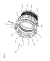
- Fig. 1 shows a perspective view of a nozzle 100 for a quick coupling system with a counter-nozzle in the locked position.
- the nozzle 100 can be used for example for a charge air connection in a motor vehicle.
- the nozzle 100 includes an insert portion 101 for inserting the nozzle and a locking bracket 103 for locking the inserted nozzle.
- the inserted counter-nozzle is in contact with a peripheral bearing surface 113 in the interior of the insert portion 101 and rests on this. By the circumferential bearing surface 113, a slot of the counter-nozzle is limited in the insert portion 101. The counter-nozzle is thus after insertion at a precisely intended position.
- the locking bracket 103 comprises a first resilient strap portion 103-1 for locking the counterpart fitting on a first side and a second resilient strap portion 103-2 for locking the counterpart fitting on a second side.
- first resilient strap portion 103-1 for locking the counterpart fitting on a first side
- second resilient strap portion 103-2 for locking the counterpart fitting on a second side.
- the one-piece locking bracket 103 is U-shaped.
- the two straight bracket sections 103-1 and 103 are connected to a bent bracket section 103-3 of the locking bracket 103.
- the locking bracket 103 is formed for example of a bent round wire.
- the locking bracket 103 is in the direction of Stutzens 100 slidably mounted.
- the locking bracket 103 is guided in two elongated openings 105-1 on one side of the nozzle 100 and two elongated openings 105-2 on the other side of the nozzle 100.
- the elongated openings 105-1 and 105-2 are designed such that they allow a lateral spread of the bracket sections 103-1 and 103-2.
- the first and second bracket portions 103-1, 103-2 are parallel to each other and engage in the groove of the counterpart nozzle.
- the cylindrical insert portion 101 for the counter-nozzle is radially widened on two opposite sides by a first extension portion 107-1 and a second extension portion 107-2.
- the extension portions 107-1 and 107-2 widen the circular shape of the cylindrical insert portion 101 in an arcuate manner and allow lateral spreading of the locking bracket 103rd
- the elongated openings 105-1 and 105-2 are arranged in the extension portions 107-1 and 107-2.
- the first and second bracket portions 103-1 and 103-2 pass through the extension portions 107-1 and 107-2 in a chordal manner.
- the end portions 109-1, 109-2 of the first and second resilient strap portions 103-1, 103-2 are angled or bent to prevent inadvertent slipping out of the locking bracket 103 from the elongated openings 105-1 and 105-2 of the insert portion 101 prevent.
- the insert portion 101 comprises a recess 111 in the direction of insertion of the counterpart nozzle for receiving a complementary projection of the counterpart nozzle. Through it is achieved that the counter-nozzle can be used only in a designated orientation in the insert portion 101.
- the recess 111 has a rectangular shape in cross section.
- Fig. 2 shows a plan view of the nozzle 100 for the quick coupling system in the locked position.
- the two straight strap sections 103-1 and 103-2 are arranged parallel to one another.
- the bracket portions 103-1 and 103-2 are pressed radially outward and then spring into a groove of the counterpart nozzle. The counter-nozzle can then not be detached from the insert portion 100 even when pulled in the axial direction.
- the locking bracket 103 is always in the closed and locked state. To release the quick release system, the locking bracket 103 in the direction of Insert section 101 pressed. After releasing the locking bracket 103 automatically returns to the initial state in which the two strap sections 103-1 and 103-2 are parallel. The end portions 109-1 and 109-2 are bent in the direction of the wall of the insert portion 101.
- Fig. 3 shows a perspective view of the nozzle 100 for the quick coupling system with a counter-nozzle in the unlocked position.
- the unlocking position is achieved in that the locking bracket 103 is pressed radially in the direction of the arrow 100 in the direction of the arrow.
- the inside of the locking bracket 103 comes into contact with the edge of the elongated openings 105-1 and 105-2, so that the bracket sections 103-1 and 103-2 spread outwards and release the counterpart.
- the third bracket portion 103-3 of the lock bracket 103 serves to spread the first and second resilient bracket portions 103-1, 103-2 when the lock bracket 103 is pushed toward the insert portion 101.
- the two become the bracket portions 103-1 and 103 -2 of the locking bracket 103 in the elongated openings 105-1 and 105-2 guided radially outward.
- Fig. 4 shows a plan view of the nozzle 100 for the quick release system in unlocking position when pressing the locking bracket 103 in the arrow direction.
- the resilient strap portions 103-1, 103-2 are spread in a V-shape and release the inserted counter-stub by removing them from the groove of the counter-stub.
- the counter-nozzle can be pulled axially out of the insert portion 101 in this state.
- the spraying of the locking bracket 103 is limited to the outside by the shape of the elongated openings 105-1 and 105-2.
- the nozzle 100 is formed for example by a plastic molding.
- a sealing ring can be arranged on the circumferential support surface 113 for the counterpart piece.
- the circumferential bearing surface 113 serves for positioning the counterpart nozzle on the nozzle 100.
- an optional sealing ring can be arranged on the opposite side of the bearing surface 113 relative to the nozzle.
- the sealing ring is configured to provide an effective seal between the nozzle 100 and the nozzle.
- the stub is part of a quick release system that includes a counterpart with a circumferential groove for engaging the first resilient stirrup portion 103-1 and the second resilient stirrup portion 103-1.
- nozzle 100 Through the nozzle 100, a compact, space-optimized quick coupling system for tool-free assembly and disassembly is realized. Since the locking bracket 103 for disassembly does not have to be dismantled or pulled and is always in lockable state, operating errors can be excluded.
- the counter-nozzle can be solved by pressing the locking bracket 103 in a simple and fast manner.
- nozzle 100 for the quick coupling and the quick coupling system thus simultaneously a mounting security, assembly and disassembly without tools, a small number of items and a compact design are realized.
Abstract
Die vorliegende Erfindung betrifft einen Stutzen (100) für ein Schnellkupplungssystem mit einem Gegenstutzen. Der Stutzen (100) umfasst einen Einsatzabschnitt (101) zum Einsetzen des Gegenstutzens und einen Verriegelungsbügel (103) mit einem ersten federnden Bügelabschnitt (103-1) zum Verriegeln des Gegenstutzens innerhalb des Einsatzabschnittes (101) an einer ersten Seite; einem zweiten federnden Bügelabschnitt (103-2) zum Verriegeln des Gegenstutzens innerhalb des Einsatzabschnittes (101) an einer zweiten Seite; und einem dritten Bügelabschnitt (103-3) zum Spreizen des ersten und des zweiten federnden Bügelabschnitts (103-1, 103-2) durch Drücken des Verriegelungsbügels (103) in Richtung des Einsatzabschnittes (101), um den Gegenstutzen zu entriegeln.The present invention relates to a nozzle (100) for a quick coupling system with a counter-nozzle. The nozzle (100) includes an insert portion (101) for inserting the nozzle and a locking bracket (103) having a first resilient strap portion (103-1) for locking the counterpart connector within the insert portion (101) on a first side; a second resilient strap portion (103-2) for locking the opposing stem within the insert portion (101) on a second side; and a third stirrup portion (103-3) for spreading the first and second resilient stirrup portions (103-1, 103-2) by urging the locking stirrup (103) toward the insert portion (101) to unlock the counter stub.
Description
Die vorliegende Erfindung betrifft einen Stutzen für ein Schnellkupplungssystem mit einem Gegenstutzen, der einen Einsatzabschnitt zum Einsetzen des Gegenstutzens und einen Verriegelungsbügel umfasst.The present invention relates to a nozzle for a quick coupling system with a counter-nozzle, comprising an insert portion for inserting the nozzle and a locking bracket.
Es ist die der Erfindung zugrundeliegende Aufgabe, einen Stutzen für ein Schnellkupplungssystem anzugeben, das auf einfache Art und Weise verriegelt und entriegelt werden kann.It is the object underlying the invention to provide a nozzle for a quick release system, which can be locked and unlocked in a simple manner.
Diese Aufgabe wird durch Gegenstände mit den Merkmalen nach den unabhängigen Ansprüchen gelöst. Vorteilhafte Ausführungsformen der Erfindung sind Gegenstand der Figuren, der Beschreibung und der abhängigen Ansprüche.This object is achieved by articles having the features according to the independent claims. Advantageous embodiments of the invention are the subject of the figures, the description and the dependent claims.
Gemäß einem ersten Aspekt der Erfindung wird die Aufgabe durch einen Stutzen für ein Schnellkupplungssystem mit einem Gegenstutzen gelöst, der einen Einsatzabschnitt zum Einsetzen des Gegenstutzens und einen Verriegelungsbügel umfasst, mit einem ersten federnden Bügelabschnitt zum Verriegeln des Gegenstutzens innerhalb des Einsatzabschnittes an einer ersten Seite; einem zweiten federnden Bügelabschnitt zum Verriegeln des Gegenstutzens innerhalb des Einsatzabschnittes an einer zweiten Seite; und einem dritten Bügelabschnitt zum Spreizen des ersten und des zweiten federnden Bügelabschnitts durch Drücken des Verriegelungsbügels in Richtung des Einsatzabschnittes, um den Gegenstutzen zu entriegeln. Dadurch wird beispielsweise der technische Vorteil erreicht, dass der Gegenstutzen bei einem Einschieben in den Einsatzabschnitt automatisch verriegelt wird und in schneller Weise durch Drücken des Verriegelungsbügels gelöst werden kann. Da der Verriegelungsbügel zur Demontage des Schnellkupplungssystems nicht demontiert oder gezogen wird und sich stets im verriegelungsfähigen Zustand befindet, werden Fehlbedienungen ausgeschlossen.According to a first aspect of the invention, the object is achieved by a nozzle for a quick coupling system with a counter-nozzle, comprising an insert portion for inserting the nozzle and a locking bracket, with a first resilient strap portion for locking the counterpart nozzle within the insert portion on a first side; a second resilient strap portion for locking the opposing neck within the insert portion on a second side; and a third stirrup portion for straddling the first and second resilient stirrup portions by urging the locking stirrup toward the insert portion to unlock the counter stub. As a result, for example, the technical advantage is achieved that the counter-nozzle is automatically locked when inserted into the insert section and can be solved in a quick manner by pressing the locking clip. Since the locking bracket for disassembly of the quick-release system is not dismantled or pulled and is always in lockable state, operating errors are excluded.
In einer vorteilhaften Ausführungsform des Stutzens ist der Verriegelungsbügel u-förmig oder v-förmig. Dadurch wird beispielsweise der technische Vorteil erreicht, dass eine einfache Grundform des Verriegelungsbügels erhalten wird, durch die sich der Verriegelungsbügel beim Drücken in Richtung des Einsatzabschnittes automatisch spreizt.In an advantageous embodiment of the neck of the locking bracket is u-shaped or v-shaped. As a result, for example, the technical advantage is achieved that a simple basic shape of the locking bracket is obtained, through which the locking bracket spreads automatically when pressed in the direction of the insert section.
In einer weiteren vorteilhaften Ausführungsform des Stutzens ist der Verriegelungsbügel aus einem gebogenen Draht mit rundem, ovalem oder rechteckigen Querschnitt gebildet.In a further advantageous embodiment of the neck of the locking bracket is formed of a bent wire with a round, oval or rectangular cross-section.
Dadurch wird beispielsweise der technische Vorteil erreicht, dass der Verriegelungsbügel auf einfache Weise hergestellt werden kann.As a result, for example, the technical advantage is achieved that the locking bracket can be made in a simple manner.
In einer weiteren vorteilhaften Ausführungsform des Stutzens umfasst der Einsatzabschnitt eine erste gestreckte Öffnung zum seitlichen Führen des ersten federnden Bügelabschnitt bei dem Spreizen und eine zweite gestreckte Öffnung zum seitlichen Führen des zweiten federnden Bügelabschnitt beim Spreizen. Dadurch wird beispielsweise der technische Vorteil erreicht, dass sich der Verriegelungsbügel in den gestreckten Öffnungen seitlich spreizen kann und in Längsrichtung durch die gestreckten Öffnungen in Position gehalten wird.In a further advantageous embodiment of the neck, the insert portion comprises a first elongated opening for laterally guiding the first resilient strap portion in the spreading and a second elongated opening for laterally guiding the second resilient strap portion during spreading. Thereby, for example, the technical advantage is achieved that the locking bracket can spread laterally in the elongated openings and is held in the longitudinal direction by the elongated openings in position.
In einer weiteren vorteilhaften Ausführungsform des Stutzens ist die erste gestreckte Öffnung in einem ersten Erweiterungsabschnitt zum radialen Erweitern des Einsatzabschnittes angeordnet und die zweite gestreckte Öffnung in einem zweiten Erweiterungsabschnitt zum radialen Erweitern des Einsatzabschnittes angeordnet. Dadurch wird beispielsweise der technische Vorteil erreicht, dass eine seitliche Spreizung des Verriegelungsbügels in den gestreckten Öffnungen erleichtert wird.In a further advantageous embodiment of the neck, the first elongated opening is arranged in a first extension section for radially expanding the insert section, and the second elongate opening is arranged in a second extension section for radially widening the insert section. As a result, for example, the technical advantage is achieved that a lateral spread of the locking bracket is facilitated in the elongated openings.
In einer weiteren vorteilhaften Ausführungsform des Stutzens sind der erste und der zweite Erweiterungsabschnitt im Querschnitt bogenförmig. Dadurch wird beispielsweise der technische Vorteil erreicht, dass die Festigkeit des Einsatzabschnittes aufrechterhalten wird.In a further advantageous embodiment of the neck, the first and the second extension portion are arcuate in cross section. As a result, for example, the technical advantage is achieved that the strength of the insert portion is maintained.
In einer weiteren vorteilhaften Ausführungsform des Stutzens sind die Endabschnitte des ersten und des zweiten federnden Bügelabschnittes abgewinkelt, um ein Herausrutschen des Verriegelungsbügels aus dem Einsatzabschnittes zu verhindern. Dadurch wird beispielsweise der technische Vorteil erreicht, dass der Verriegelungsbügel an dem Einsatzabschnitt gehalten wird.In a further advantageous embodiment of the neck, the end portions of the first and second resilient strap portion are angled to prevent slipping out of the locking bracket from the insert portion. As a result, for example, the technical advantage is achieved that the locking bracket is held on the insert portion.
In einer weiteren vorteilhaften Ausführungsform des Stutzens verlaufen der erste und der zweite Bügelabschnitt kreissehnenförmig innerhalb des Einsatzabschnittes. Dadurch wird beispielsweise der technische Vorteil erreicht, dass eine feste Verriegelung des Gegenstutzens erreicht wird.In a further advantageous embodiment of the neck, the first and the second bow section extend in a circular chord shape within the insert section. As a result, for example, the technical advantage is achieved that a solid locking of the counter-nozzle is achieved.
In einer weiteren vorteilhaften Ausführungsform des Stutzens sind der erste und der zweite Bügelabschnitt parallel zueinander angeordnet. Dadurch wird beispielsweise der technische Vorteil erreicht, dass der Gegenstutzen auf gegenüberliegenden Seiten mit einer symmetrischen Kraft gehalten wird.In a further advantageous embodiment of the neck, the first and the second bracket portion are arranged parallel to each other. As a result, for example, the technical advantage is achieved that the counter-nozzle is held on opposite sides with a symmetrical force.
In einer weiteren vorteilhaften Ausführungsform des Stutzens umfasst der Stutzen eine umlaufende Auflagefläche für ein Ende des Gegenstutzens. Dadurch wird beispielsweise der technische Vorteil erreicht, dass der Gegenstutzen beim Einschieben in den Einsatzabschnitt einen Anschlag findet.In a further advantageous embodiment of the neck, the neck comprises a peripheral bearing surface for one end of the nozzle. As a result, for example, the technical advantage is achieved that the counter-piece when inserting into the insert section finds a stop.
In einer weiteren vorteilhaften Ausführungsform des Stutzens umfasst die umlaufende Auflagefläche einen Dichtring. Dadurch wird beispielsweise der technische Vorteil erreicht, dass eine fluiddichte Verbindung zwischen Stutzen und Gegenstutzen erreicht wird.In a further advantageous embodiment of the neck, the circumferential bearing surface comprises a sealing ring. As a result, for example, the technical advantage is achieved that a fluid-tight connection between the nozzle and counter-nozzle is achieved.
In einer weiteren vorteilhaften Ausführungsform des Stutzens umfasst der Einsatzabschnitt eine Aussparung in Einsatzrichtung zum Aufnehmen eines Vorsprungs des Gegenstutzens. Dadurch wird beispielsweise der technische Vorteil erreicht, dass der Gegenstutzen nur in einer vorgesehenen Lage eingesetzt werden kann.In a further advantageous embodiment of the neck, the insert portion comprises a recess in the insertion direction for receiving a projection of the nozzle piece. As a result, for example, the technical advantage is achieved that the counter-nozzle can be used only in a designated location.
In einer weiteren vorteilhaften Ausführungsform des Stutzens ist die Aussparung im Querschnitt rechteckig. Dadurch wird beispielsweise der technische Vorteil erreicht, dass ein Verdrehen des Gegenstutzens in dem Einsatzabschnitt verhindert wird.In a further advantageous embodiment of the neck, the recess is rectangular in cross section. As a result, for example, the technical advantage is achieved that a rotation of the counterpart piece is prevented in the insert section.
In einer weiteren vorteilhaften Ausführungsform des Stutzens ist ein Körper des Stutzens durch ein Kunststoffformteil gebildet. Dadurch wird beispielsweise der technische Vorteil erreicht, dass der Stutzen auf einfache Weise in der gewünschten Form hergestellt werden kann.In a further advantageous embodiment of the neck, a body of the neck is formed by a plastic molding. As a result, for example, the technical advantage is achieved that the nozzle can be easily manufactured in the desired shape.
Gemäß einem ersten Aspekt der Erfindung wird die Aufgabe durch ein Schnellkupplungssystem mit einem Stutzen nach dem ersten Aspekt und einem Gegenstutzen mit einer umlaufenden Nut zum Eingreifen des ersten federnden Bügelabschnittes und des zweiten federnden Bügelabschnittes gelöst. Dadurch wird beispielsweise ebenfalls der technische Vorteil erreicht, dass der Gegenstutzen bei einem Einschieben in den Einsatzabschnitt automatisch verriegelt wird und in schneller Weise durch Drücken des Verriegelungsbügels gelöst werden kann.According to a first aspect of the invention, the object is achieved by a quick coupling system with a nozzle according to the first aspect and a counter-nozzle with a circumferential groove for engaging the first resilient strap portion and the second resilient strap portion. As a result, for example, the technical advantage is achieved that the counter-nozzle is automatically locked when inserted into the insert section and can be solved in a quick manner by pressing the locking bracket.
Ausführungsbeispiele der Erfindung sind in den Zeichnungen dargestellt und werden im Folgenden näher beschrieben.Embodiments of the invention are illustrated in the drawings and will be described in more detail below.
Es zeigen:
- Fig. 1
- eine perspektivische Ansicht eines Stutzens für ein Schnellkupplungssystem in Verriegelungsposition;
- Fig. 2
- eine Aufsicht des Stutzens für das Schnellkupplungssystem in Verriegelungsposition;
- Fig. 3
- eine perspektivische Ansicht des Stutzens für das Schnellkupplungssystem in Entriegelungsposition; und
- Fig. 4
- eine Aufsicht des Stutzens für das Schnellkupplungssystem in Entriegelungsposition.
- Fig. 1
- a perspective view of a nozzle for a quick release system in the locked position;
- Fig. 2
- a plan view of the nozzle for the quick coupling system in the locked position;
- Fig. 3
- a perspective view of the nozzle for the quick release system in unlocked position; and
- Fig. 4
- a view of the nozzle for the quick coupling system in unlocking position.
Der Verriegelungsbügel 103 umfasst einen ersten federnden Bügelabschnitt 103-1 zum Verriegeln des Gegenstutzens an einer ersten Seite und einen zweiten federnden Bügelabschnitt 103-2 zum Verriegeln des Gegenstutzen an einer zweiten Seite. Beim Einsetzen des Gegenstutzens in den Einsatzabschnitt 101 werden die beiden Bügelabschnitte 103-1 und 103-2 zunächst nach Außen gedrückt und rasten dann federnd in einer umlaufenden Nut des Gegenstutzens ein. Die Nut befindet sich in der gleichen Tiefe des Einsatzabschnittes 101 wie die federnden Bügelabschnitte 103-1 und 103-2. Durch das Einfedern der Bügelabschnitte 103-1 und 103-2 wird der Gegenstutzen an dem Stutzen 100 arretiert.The
Der einstückige Verriegelungsbügel 103 ist u-förmig ausgebildet. Die beiden geraden Bügelabschnitte 103-1 und 103 sind mit einem gebogenen Bügelabschnitt 103-3 des Verriegelungsbügels 103 verbunden. Der Verriegelungsbügel 103 ist beispielsweise aus einem gebogenen Runddraht gebildet. Der Verriegelungsbügel 103 ist in Richtung des Stutzens 100 verschiebbar gelagert. Der Verriegelungsbügel 103 ist in zwei gestreckten Öffnungen 105-1 an einer Seite des Stutzens 100 und zwei gestreckten Öffnungen 105-2 an der anderen Seite des Stutzens 100 geführt. Die gestreckten Öffnungen 105-1 und 105-2 sind derart gestaltet, dass diese eine seitliche Spreizung der Bügelabschnitte 103-1 und 103-2 zulassen. In der Verriegelungsposition liegen der erste und der zweite Bügelabschnitt 103-1, 103-2 parallel zueinander und greifen in die Nut des Gegenstutzens ein.The one-
Der zylindrische Einsatzabschnitt 101 für den Gegenstutzen ist an zwei gegenüberliegenden Seiten durch einen ersten Erweiterungsabschnitt 107-1 und einen zweiten Erweiterungsabschnitt 107-2 radial verbreitert. Die Erweiterungsabschnitte 107-1 und 107-2 verbreitern die Kreisform des zylindrischen Einsatzabschnittes 101 in bogenförmiger Weise und ermöglichen eine seitliche Spreizung des Verriegelungsbügels 103.The
Die gestreckten Öffnungen 105-1 und 105-2 sind in den Erweiterungsabschnitten 107-1 und 107-2 angeordnet. Der erste und der zweite Bügelabschnitt 103-1 und 103-2 durchlaufen die Erweiterungsabschnitte 107-1 und 107-2 sehnenartig. Die Endabschnitte 109-1, 109-2 des ersten und des zweiten federnden Bügelabschnittes 103-1, 103-2 sind abgewinkelt oder abgebogen, um ein unbeabsichtigtes Herausrutschen des Verriegelungsbügels 103 aus den gestreckten Öffnungen 105-1 und 105-2 des Einsatzabschnittes 101 zu verhindern.The elongated openings 105-1 and 105-2 are arranged in the extension portions 107-1 and 107-2. The first and second bracket portions 103-1 and 103-2 pass through the extension portions 107-1 and 107-2 in a chordal manner. The end portions 109-1, 109-2 of the first and second resilient strap portions 103-1, 103-2 are angled or bent to prevent inadvertent slipping out of the
Der Einsatzabschnitt 101 umfasst eine Aussparung 111 in Einsatzrichtung des Gegenstutzens zum Aufnehmen eines komplementären Vorsprungs des Gegenstutzens. Durch wird erreicht, dass der Gegenstutzen nur in einer vorgesehenen Orientierung in den Einsatzabschnitt 101 eingesetzt werden kann. Die Aussparung 111 weist im Querschnitt eine rechteckige Form auf.The
Der Verriegelungsbügel 103 befindet sich stets im geschlossenen und verriegelten Zustand. Zum Lösen des Schnellkupplungssystems wird der Verriegelungsbügel 103 in Richtung des Einsatzabschnittes 101 gedrückt. Nach dem Loslassen kehrt der Verriegelungsbügel 103 automatisch in den Ausgangszustand zurück, in dem die beiden Bügelabschnitte 103-1 und 103-2 parallel liegen. Die Endabschnitte 109-1 und 109-2 sind in Richtung der Wandung des Einsatzabschnittes 101 abgebogen.The locking
Der dritte Bügelabschnitt 103-3 des Verriegelungsbügels 103 dient daher zum Spreizen des ersten und des zweiten federnden Bügelabschnitts 103-1, 103-2 beim Drücken des Verriegelungsbügels 103 in Richtung des Einsatzabschnittes 101. Beim Spreizen werden die beiden die Bügelabschnitte 103-1 und 103-2 des Verriegelungsbügels 103 in den gestreckten Öffnungen 105-1 und 105-2 radial nach Außen geführt.Therefore, the third bracket portion 103-3 of the
Der Stutzen 100 wird beispielsweise durch ein Kunststoffformteil gebildet. Zum Erhöhen einer Dichtigkeit kann in einer Ausführungsform auf der umlaufenden Auflagefläche 113 für den Gegenstutzen ein Dichtring angeordnet sein. In einer anderen Ausführungsform dient die umlaufende Auflagefläche 113 zur Positionierung des Gegenstutzens an dem Stutzen 100. Auf der in Bezug auf den Gegenstutzen entgegengesetzten Seite der Auflagefläche 113 kann optional ein Dichtring angeordnet werden. Der Dichtring ist ausgebildet, um eine wirksame Dichtung zwischen dem Stutzen 100 und dem Gegenstutzen bereitzustellen. Der Stutzen ist ein Teil eines Schnellkupplungssystems, das einen Gegenstutzen mit einer umlaufenden Nut zum Eingreifen des ersten federnden Bügelabschnittes 103-1 und des zweiten federnden Bügelabschnittes 103-1.The
Durch den Stutzen 100 wird ein kompaktes, bauraumoptimiertes Schnellkupplungssystem zur werkzeuglosen Montage und Demontage realisiert. Da der Verriegelungsbügel 103 zur Demontage nicht demontiert oder gezogen werden muss und sich stets im verriegelungsfähigen Zustand befindet, können Fehlbedienungen ausgeschlossen werden. Der Gegenstutzen kann durch Drücken des Verriegelungsbügels 103 in einfacher und schneller Weise gelöst werden.Through the
Das lediglich drei Teile, nämlich Stutzen 100, Verriegelungsbügel 103 und Gegenstutzen, umfassende Schnellkupplungssystem zeichnet sich durch eine besonders kompakte Bauform aus und kann direkt in ein Kunststoffrohr integriert werden, beispielsweise mittels Spritzgießens. Durch den Stutzen 100 für die Schnellkupplung und das Schnellkupplungssystem werden somit gleichzeitig eine Montagesicherheit, eine Montage und Demontage ohne Werkzeug, eine geringe Anzahl von Einzelteilen und eine kompakte Bauform realisiert.The only three parts, namely
Alle in Verbindung mit einzelnen Ausführungsformen der Erfindung erläuterten und gezeigten Merkmale können in unterschiedlicher Kombination in dem erfindungsgemäßen Gegenstand vorgesehen sein, um gleichzeitig deren vorteilhafte Wirkungen zu realisieren.All of the features explained and shown in connection with individual embodiments of the invention may be provided in different combinations in the article according to the invention in order to simultaneously realize their advantageous effects.
Der Schutzbereich der vorliegenden Erfindung ist durch die Ansprüche gegeben und wird durch die in der Beschreibung erläuterten oder den Figuren gezeigten Merkmale nicht beschränkt.The scope of the present invention is given by the claims and is not limited by the features illustrated in the specification or shown in the figures.
- 100100
- StutzenSupport
- 101101
- Einsatzabschnittinsert portion
- 103103
- Verriegelungsbügellocking clip
- 103-1103-1
- Bügelabschnittbow section
- 103-2103-2
- Bügelabschnittbow section
- 103-3103-3
- Bügelabschnittbow section
- 105-1105-1
- Öffnungopening
- 105-2105-2
- Öffnungopening
- 107-1107-1
- ErweiterungsabschnittEnhancements section
- 107-2107-2
- ErweiterungsabschnittEnhancements section
- 109109
- Endabschnittend
- 111111
- Aussparungrecess
- 113113
- Auflageflächebearing surface
Claims (15)
einem ersten federnden Bügelabschnitt (103-1) zum Verriegeln des Gegenstutzens innerhalb des Einsatzabschnittes (101) an einer ersten Seite;
einem zweiten federnden Bügelabschnitt (103-2) zum Verriegeln des Gegenstutzens innerhalb des Einsatzabschnittes (101) an einer zweiten Seite; und
einem dritten Bügelabschnitt (103-3) zum Spreizen des ersten und des zweiten federnden Bügelabschnitts (103-1, 103-2) durch Drücken des Verriegelungsbügels (103) in Richtung des Einsatzabschnittes (101), um den Gegenstutzen zu entriegeln.Connecting piece (100) for a quick coupling system with a counter-nozzle, which comprises an insert portion (101) for inserting the nozzle piece and a locking bracket (103), with
a first resilient strap portion (103-1) for locking the opposing neck within the insert portion (101) on a first side;
a second resilient strap portion (103-2) for locking the opposing stem within the insert portion (101) on a second side; and
a third stirrup portion (103-3) for spreading the first and second resilient stirrup portions (103-1, 103-2) by urging the locking stirrup (103) toward the insert portion (101) to unlock the counter stub.
Applications Claiming Priority (1)
| Application Number | Priority Date | Filing Date | Title |
|---|---|---|---|
| DE102014101212.7A DE102014101212A1 (en) | 2014-01-31 | 2014-01-31 | Nozzle for a quick coupling system |
Publications (1)
| Publication Number | Publication Date |
|---|---|
| EP2902688A1 true EP2902688A1 (en) | 2015-08-05 |
Family
ID=52350029
Family Applications (1)
| Application Number | Title | Priority Date | Filing Date |
|---|---|---|---|
| EP15151605.1A Withdrawn EP2902688A1 (en) | 2014-01-31 | 2015-01-19 | Socket for a quick-acting coupling system |
Country Status (2)
| Country | Link |
|---|---|
| EP (1) | EP2902688A1 (en) |
| DE (1) | DE102014101212A1 (en) |
Citations (6)
| Publication number | Priority date | Publication date | Assignee | Title |
|---|---|---|---|---|
| WO1996010712A1 (en) * | 1994-09-30 | 1996-04-11 | Lewis Philip C | A universal pipe coupling with a u-shaped clip member |
| JP2001289381A (en) * | 2000-04-05 | 2001-10-19 | Togo Seisakusho Corp | Connector |
| FR2855590A1 (en) * | 2003-05-27 | 2004-12-03 | Caillau Ets | QUICK CONNECTION PLUG |
| FR2863034A1 (en) * | 2003-11-28 | 2005-06-03 | Tokai Rubber Ind Ltd | QUICK COUPLING |
| US20080277929A1 (en) * | 2007-05-10 | 2008-11-13 | Bucher Michael R | Quick connector for fluid conduit |
| EP2372209A2 (en) * | 2010-03-30 | 2011-10-05 | NORMA Germany GmbH | Exhaust gas pipe for a motor vehicle and exhaust gas unit |
-
2014
- 2014-01-31 DE DE102014101212.7A patent/DE102014101212A1/en not_active Withdrawn
-
2015
- 2015-01-19 EP EP15151605.1A patent/EP2902688A1/en not_active Withdrawn
Patent Citations (6)
| Publication number | Priority date | Publication date | Assignee | Title |
|---|---|---|---|---|
| WO1996010712A1 (en) * | 1994-09-30 | 1996-04-11 | Lewis Philip C | A universal pipe coupling with a u-shaped clip member |
| JP2001289381A (en) * | 2000-04-05 | 2001-10-19 | Togo Seisakusho Corp | Connector |
| FR2855590A1 (en) * | 2003-05-27 | 2004-12-03 | Caillau Ets | QUICK CONNECTION PLUG |
| FR2863034A1 (en) * | 2003-11-28 | 2005-06-03 | Tokai Rubber Ind Ltd | QUICK COUPLING |
| US20080277929A1 (en) * | 2007-05-10 | 2008-11-13 | Bucher Michael R | Quick connector for fluid conduit |
| EP2372209A2 (en) * | 2010-03-30 | 2011-10-05 | NORMA Germany GmbH | Exhaust gas pipe for a motor vehicle and exhaust gas unit |
Also Published As
| Publication number | Publication date |
|---|---|
| DE102014101212A1 (en) | 2015-08-06 |
Similar Documents
| Publication | Publication Date | Title |
|---|---|---|
| DE10115399C1 (en) | Detachable push-fit coupling, for fluid pipes, has insert part and housing and with additional locking element displaced crosswise between opening and closing position | |
| WO2014019757A1 (en) | Quick connection arrangement for detachably connecting a media line to a connecting piece | |
| EP1969280B1 (en) | Plug-in part for a plug connector arrangement | |
| EP3396786A1 (en) | Connector assembly | |
| EP0568075B1 (en) | Plug-in connector for hoses or pipe conduits especially for fuel conduits of combustion engines | |
| EP2017520B1 (en) | Assembly of Thermostat and radiatorhousing, as well as their attaching device | |
| WO2001061223A1 (en) | Rotatable stopcock for a male coupling having a 90° offset connecting piece | |
| DE10025817C2 (en) | Detachable quick coupling with safety catch | |
| DE19848289C2 (en) | Locking device of a cap part | |
| DE102013222411A1 (en) | Connectors | |
| DE4217646C1 (en) | Push in connector for two pipe sections - has coaxially interfitting connectors with spring clip locked even in release position on one part by locking element with detent allowing pre-fitting | |
| DE102015213751A1 (en) | connector | |
| EP2902688A1 (en) | Socket for a quick-acting coupling system | |
| EP3244113A1 (en) | Locking strap for a support of a quick coupling system | |
| WO2009144098A1 (en) | Plug connection for fluid conduits | |
| DE102012102639A1 (en) | Cable connector for arranging wiring harness in head light of vehicle, has cable tie strap which is coupled to wiring harness with connecting elements arranged on rear portion of pins, opposing the side of latching sleeve | |
| DE1765099B2 (en) | ELECTRIC CONNECTOR | |
| EP0455972B1 (en) | Supporting device for the simultaneous coupling of several parallel arranged fluid connectors | |
| DE4022769C2 (en) | Pipe multiple coupling | |
| EP3153757B1 (en) | Detachable plug connection for pipes | |
| DE102017125794A1 (en) | connector | |
| EP2927472B1 (en) | Connector | |
| DE3901104C2 (en) | Connector with locking function for fluid-carrying lines | |
| DE102017004266A1 (en) | Connector, plug and connector system | |
| DE102021102585A1 (en) | Plug connections for the detachable connection of lines and system comprising such a plug connection |
Legal Events
| Date | Code | Title | Description |
|---|---|---|---|
| PUAI | Public reference made under article 153(3) epc to a published international application that has entered the european phase |
Free format text: ORIGINAL CODE: 0009012 |
|
| 17P | Request for examination filed |
Effective date: 20150119 |
|
| AK | Designated contracting states |
Kind code of ref document: A1 Designated state(s): AL AT BE BG CH CY CZ DE DK EE ES FI FR GB GR HR HU IE IS IT LI LT LU LV MC MK MT NL NO PL PT RO RS SE SI SK SM TR |
|
| AX | Request for extension of the european patent |
Extension state: BA ME |
|
| 17P | Request for examination filed |
Effective date: 20151009 |
|
| RBV | Designated contracting states (corrected) |
Designated state(s): AL AT BE BG CH CY CZ DE DK EE ES FI FR GB GR HR HU IE IS IT LI LT LU LV MC MK MT NL NO PL PT RO RS SE SI SK SM TR |
|
| 17Q | First examination report despatched |
Effective date: 20160210 |
|
| STAA | Information on the status of an ep patent application or granted ep patent |
Free format text: STATUS: THE APPLICATION IS DEEMED TO BE WITHDRAWN |
|
| 18D | Application deemed to be withdrawn |
Effective date: 20160621 |