EP2902248A2 - Vehicle and battery pack and method for controlling a battery pack assembly - Google Patents
Vehicle and battery pack and method for controlling a battery pack assembly Download PDFInfo
- Publication number
- EP2902248A2 EP2902248A2 EP14192016.5A EP14192016A EP2902248A2 EP 2902248 A2 EP2902248 A2 EP 2902248A2 EP 14192016 A EP14192016 A EP 14192016A EP 2902248 A2 EP2902248 A2 EP 2902248A2
- Authority
- EP
- European Patent Office
- Prior art keywords
- battery pack
- vehicle
- battery
- management system
- master
- Prior art date
- Legal status (The legal status is an assumption and is not a legal conclusion. Google has not performed a legal analysis and makes no representation as to the accuracy of the status listed.)
- Granted
Links
Images


Classifications
-
- B—PERFORMING OPERATIONS; TRANSPORTING
- B60—VEHICLES IN GENERAL
- B60L—PROPULSION OF ELECTRICALLY-PROPELLED VEHICLES; SUPPLYING ELECTRIC POWER FOR AUXILIARY EQUIPMENT OF ELECTRICALLY-PROPELLED VEHICLES; ELECTRODYNAMIC BRAKE SYSTEMS FOR VEHICLES IN GENERAL; MAGNETIC SUSPENSION OR LEVITATION FOR VEHICLES; MONITORING OPERATING VARIABLES OF ELECTRICALLY-PROPELLED VEHICLES; ELECTRIC SAFETY DEVICES FOR ELECTRICALLY-PROPELLED VEHICLES
- B60L3/00—Electric devices on electrically-propelled vehicles for safety purposes; Monitoring operating variables, e.g. speed, deceleration or energy consumption
- B60L3/0023—Detecting, eliminating, remedying or compensating for drive train abnormalities, e.g. failures within the drive train
- B60L3/0046—Detecting, eliminating, remedying or compensating for drive train abnormalities, e.g. failures within the drive train relating to electric energy storage systems, e.g. batteries or capacitors
-
- B—PERFORMING OPERATIONS; TRANSPORTING
- B60—VEHICLES IN GENERAL
- B60L—PROPULSION OF ELECTRICALLY-PROPELLED VEHICLES; SUPPLYING ELECTRIC POWER FOR AUXILIARY EQUIPMENT OF ELECTRICALLY-PROPELLED VEHICLES; ELECTRODYNAMIC BRAKE SYSTEMS FOR VEHICLES IN GENERAL; MAGNETIC SUSPENSION OR LEVITATION FOR VEHICLES; MONITORING OPERATING VARIABLES OF ELECTRICALLY-PROPELLED VEHICLES; ELECTRIC SAFETY DEVICES FOR ELECTRICALLY-PROPELLED VEHICLES
- B60L50/00—Electric propulsion with power supplied within the vehicle
- B60L50/20—Electric propulsion with power supplied within the vehicle using propulsion power generated by humans or animals
-
- B—PERFORMING OPERATIONS; TRANSPORTING
- B60—VEHICLES IN GENERAL
- B60L—PROPULSION OF ELECTRICALLY-PROPELLED VEHICLES; SUPPLYING ELECTRIC POWER FOR AUXILIARY EQUIPMENT OF ELECTRICALLY-PROPELLED VEHICLES; ELECTRODYNAMIC BRAKE SYSTEMS FOR VEHICLES IN GENERAL; MAGNETIC SUSPENSION OR LEVITATION FOR VEHICLES; MONITORING OPERATING VARIABLES OF ELECTRICALLY-PROPELLED VEHICLES; ELECTRIC SAFETY DEVICES FOR ELECTRICALLY-PROPELLED VEHICLES
- B60L50/00—Electric propulsion with power supplied within the vehicle
- B60L50/50—Electric propulsion with power supplied within the vehicle using propulsion power supplied by batteries or fuel cells
- B60L50/60—Electric propulsion with power supplied within the vehicle using propulsion power supplied by batteries or fuel cells using power supplied by batteries
- B60L50/64—Constructional details of batteries specially adapted for electric vehicles
-
- B—PERFORMING OPERATIONS; TRANSPORTING
- B60—VEHICLES IN GENERAL
- B60L—PROPULSION OF ELECTRICALLY-PROPELLED VEHICLES; SUPPLYING ELECTRIC POWER FOR AUXILIARY EQUIPMENT OF ELECTRICALLY-PROPELLED VEHICLES; ELECTRODYNAMIC BRAKE SYSTEMS FOR VEHICLES IN GENERAL; MAGNETIC SUSPENSION OR LEVITATION FOR VEHICLES; MONITORING OPERATING VARIABLES OF ELECTRICALLY-PROPELLED VEHICLES; ELECTRIC SAFETY DEVICES FOR ELECTRICALLY-PROPELLED VEHICLES
- B60L50/00—Electric propulsion with power supplied within the vehicle
- B60L50/50—Electric propulsion with power supplied within the vehicle using propulsion power supplied by batteries or fuel cells
- B60L50/60—Electric propulsion with power supplied within the vehicle using propulsion power supplied by batteries or fuel cells using power supplied by batteries
- B60L50/66—Arrangements of batteries
-
- B—PERFORMING OPERATIONS; TRANSPORTING
- B60—VEHICLES IN GENERAL
- B60L—PROPULSION OF ELECTRICALLY-PROPELLED VEHICLES; SUPPLYING ELECTRIC POWER FOR AUXILIARY EQUIPMENT OF ELECTRICALLY-PROPELLED VEHICLES; ELECTRODYNAMIC BRAKE SYSTEMS FOR VEHICLES IN GENERAL; MAGNETIC SUSPENSION OR LEVITATION FOR VEHICLES; MONITORING OPERATING VARIABLES OF ELECTRICALLY-PROPELLED VEHICLES; ELECTRIC SAFETY DEVICES FOR ELECTRICALLY-PROPELLED VEHICLES
- B60L53/00—Methods of charging batteries, specially adapted for electric vehicles; Charging stations or on-board charging equipment therefor; Exchange of energy storage elements in electric vehicles
- B60L53/80—Exchanging energy storage elements, e.g. removable batteries
-
- B—PERFORMING OPERATIONS; TRANSPORTING
- B60—VEHICLES IN GENERAL
- B60L—PROPULSION OF ELECTRICALLY-PROPELLED VEHICLES; SUPPLYING ELECTRIC POWER FOR AUXILIARY EQUIPMENT OF ELECTRICALLY-PROPELLED VEHICLES; ELECTRODYNAMIC BRAKE SYSTEMS FOR VEHICLES IN GENERAL; MAGNETIC SUSPENSION OR LEVITATION FOR VEHICLES; MONITORING OPERATING VARIABLES OF ELECTRICALLY-PROPELLED VEHICLES; ELECTRIC SAFETY DEVICES FOR ELECTRICALLY-PROPELLED VEHICLES
- B60L58/00—Methods or circuit arrangements for monitoring or controlling batteries or fuel cells, specially adapted for electric vehicles
- B60L58/10—Methods or circuit arrangements for monitoring or controlling batteries or fuel cells, specially adapted for electric vehicles for monitoring or controlling batteries
- B60L58/18—Methods or circuit arrangements for monitoring or controlling batteries or fuel cells, specially adapted for electric vehicles for monitoring or controlling batteries of two or more battery modules
-
- B—PERFORMING OPERATIONS; TRANSPORTING
- B60—VEHICLES IN GENERAL
- B60L—PROPULSION OF ELECTRICALLY-PROPELLED VEHICLES; SUPPLYING ELECTRIC POWER FOR AUXILIARY EQUIPMENT OF ELECTRICALLY-PROPELLED VEHICLES; ELECTRODYNAMIC BRAKE SYSTEMS FOR VEHICLES IN GENERAL; MAGNETIC SUSPENSION OR LEVITATION FOR VEHICLES; MONITORING OPERATING VARIABLES OF ELECTRICALLY-PROPELLED VEHICLES; ELECTRIC SAFETY DEVICES FOR ELECTRICALLY-PROPELLED VEHICLES
- B60L58/00—Methods or circuit arrangements for monitoring or controlling batteries or fuel cells, specially adapted for electric vehicles
- B60L58/10—Methods or circuit arrangements for monitoring or controlling batteries or fuel cells, specially adapted for electric vehicles for monitoring or controlling batteries
- B60L58/24—Methods or circuit arrangements for monitoring or controlling batteries or fuel cells, specially adapted for electric vehicles for monitoring or controlling batteries for controlling the temperature of batteries
- B60L58/26—Methods or circuit arrangements for monitoring or controlling batteries or fuel cells, specially adapted for electric vehicles for monitoring or controlling batteries for controlling the temperature of batteries by cooling
-
- H—ELECTRICITY
- H02—GENERATION; CONVERSION OR DISTRIBUTION OF ELECTRIC POWER
- H02J—ELECTRIC POWER NETWORKS; CIRCUIT ARRANGEMENTS OR SYSTEMS FOR SUPPLYING OR DISTRIBUTING ELECTRIC POWER; SYSTEMS FOR STORING ELECTRIC ENERGY
- H02J7/00—Circuit arrangements for charging or discharging batteries or for supplying loads from batteries
- H02J7/34—Parallel operation in networks using both storage and other DC sources, e.g. providing buffering
- H02J7/342—The other DC source being a battery actively interacting with the first one, i.e. battery to battery charging
-
- H—ELECTRICITY
- H02—GENERATION; CONVERSION OR DISTRIBUTION OF ELECTRIC POWER
- H02J—ELECTRIC POWER NETWORKS; CIRCUIT ARRANGEMENTS OR SYSTEMS FOR SUPPLYING OR DISTRIBUTING ELECTRIC POWER; SYSTEMS FOR STORING ELECTRIC ENERGY
- H02J7/00—Circuit arrangements for charging or discharging batteries or for supplying loads from batteries
- H02J7/40—Circuit arrangements for charging or discharging batteries or for supplying loads from batteries characterised by the exchange of charge or discharge related data
- H02J7/44—Circuit arrangements for charging or discharging batteries or for supplying loads from batteries characterised by the exchange of charge or discharge related data between battery management systems and power sources
-
- H—ELECTRICITY
- H02—GENERATION; CONVERSION OR DISTRIBUTION OF ELECTRIC POWER
- H02J—ELECTRIC POWER NETWORKS; CIRCUIT ARRANGEMENTS OR SYSTEMS FOR SUPPLYING OR DISTRIBUTING ELECTRIC POWER; SYSTEMS FOR STORING ELECTRIC ENERGY
- H02J7/00—Circuit arrangements for charging or discharging batteries or for supplying loads from batteries
- H02J7/485—Circuit arrangements for charging or discharging batteries or for supplying loads from batteries with provisions for charging different types of batteries
-
- H—ELECTRICITY
- H02—GENERATION; CONVERSION OR DISTRIBUTION OF ELECTRIC POWER
- H02J—ELECTRIC POWER NETWORKS; CIRCUIT ARRANGEMENTS OR SYSTEMS FOR SUPPLYING OR DISTRIBUTING ELECTRIC POWER; SYSTEMS FOR STORING ELECTRIC ENERGY
- H02J7/00—Circuit arrangements for charging or discharging batteries or for supplying loads from batteries
- H02J7/50—Circuit arrangements for charging or discharging batteries or for supplying loads from batteries acting upon multiple batteries simultaneously or sequentially
-
- B—PERFORMING OPERATIONS; TRANSPORTING
- B60—VEHICLES IN GENERAL
- B60L—PROPULSION OF ELECTRICALLY-PROPELLED VEHICLES; SUPPLYING ELECTRIC POWER FOR AUXILIARY EQUIPMENT OF ELECTRICALLY-PROPELLED VEHICLES; ELECTRODYNAMIC BRAKE SYSTEMS FOR VEHICLES IN GENERAL; MAGNETIC SUSPENSION OR LEVITATION FOR VEHICLES; MONITORING OPERATING VARIABLES OF ELECTRICALLY-PROPELLED VEHICLES; ELECTRIC SAFETY DEVICES FOR ELECTRICALLY-PROPELLED VEHICLES
- B60L2200/00—Type of vehicles
- B60L2200/12—Bikes
-
- H—ELECTRICITY
- H01—ELECTRIC ELEMENTS
- H01M—PROCESSES OR MEANS, e.g. BATTERIES, FOR THE DIRECT CONVERSION OF CHEMICAL ENERGY INTO ELECTRICAL ENERGY
- H01M10/00—Secondary cells; Manufacture thereof
- H01M10/42—Methods or arrangements for servicing or maintenance of secondary cells or secondary half-cells
- H01M10/4207—Methods or arrangements for servicing or maintenance of secondary cells or secondary half-cells for several batteries or cells simultaneously or sequentially
-
- H—ELECTRICITY
- H01—ELECTRIC ELEMENTS
- H01M—PROCESSES OR MEANS, e.g. BATTERIES, FOR THE DIRECT CONVERSION OF CHEMICAL ENERGY INTO ELECTRICAL ENERGY
- H01M10/00—Secondary cells; Manufacture thereof
- H01M10/42—Methods or arrangements for servicing or maintenance of secondary cells or secondary half-cells
- H01M10/425—Structural combination with electronic components, e.g. electronic circuits integrated to the outside of the casing
- H01M2010/4271—Battery management systems including electronic circuits, e.g. control of current or voltage to keep battery in healthy state, cell balancing
-
- H—ELECTRICITY
- H01—ELECTRIC ELEMENTS
- H01M—PROCESSES OR MEANS, e.g. BATTERIES, FOR THE DIRECT CONVERSION OF CHEMICAL ENERGY INTO ELECTRICAL ENERGY
- H01M2220/00—Batteries for particular applications
- H01M2220/20—Batteries in motive systems, e.g. vehicle, ship, plane
-
- H—ELECTRICITY
- H02—GENERATION; CONVERSION OR DISTRIBUTION OF ELECTRIC POWER
- H02J—ELECTRIC POWER NETWORKS; CIRCUIT ARRANGEMENTS OR SYSTEMS FOR SUPPLYING OR DISTRIBUTING ELECTRIC POWER; SYSTEMS FOR STORING ELECTRIC ENERGY
- H02J2105/00—Networks for supplying or distributing electric power characterised by their spatial reach or by the load
- H02J2105/30—Networks for supplying or distributing electric power characterised by their spatial reach or by the load the load networks being external to vehicles, i.e. exchanging power with vehicles
- H02J2105/33—Networks for supplying or distributing electric power characterised by their spatial reach or by the load the load networks being external to vehicles, i.e. exchanging power with vehicles exchanging power with road vehicles
- H02J2105/37—Networks for supplying or distributing electric power characterised by their spatial reach or by the load the load networks being external to vehicles, i.e. exchanging power with vehicles exchanging power with road vehicles exchanging power with electric vehicles [EV] or with hybrid electric vehicles [HEV]
-
- Y—GENERAL TAGGING OF NEW TECHNOLOGICAL DEVELOPMENTS; GENERAL TAGGING OF CROSS-SECTIONAL TECHNOLOGIES SPANNING OVER SEVERAL SECTIONS OF THE IPC; TECHNICAL SUBJECTS COVERED BY FORMER USPC CROSS-REFERENCE ART COLLECTIONS [XRACs] AND DIGESTS
- Y02—TECHNOLOGIES OR APPLICATIONS FOR MITIGATION OR ADAPTATION AGAINST CLIMATE CHANGE
- Y02E—REDUCTION OF GREENHOUSE GAS [GHG] EMISSIONS, RELATED TO ENERGY GENERATION, TRANSMISSION OR DISTRIBUTION
- Y02E60/00—Enabling technologies; Technologies with a potential or indirect contribution to GHG emissions mitigation
- Y02E60/10—Energy storage using batteries
-
- Y—GENERAL TAGGING OF NEW TECHNOLOGICAL DEVELOPMENTS; GENERAL TAGGING OF CROSS-SECTIONAL TECHNOLOGIES SPANNING OVER SEVERAL SECTIONS OF THE IPC; TECHNICAL SUBJECTS COVERED BY FORMER USPC CROSS-REFERENCE ART COLLECTIONS [XRACs] AND DIGESTS
- Y02—TECHNOLOGIES OR APPLICATIONS FOR MITIGATION OR ADAPTATION AGAINST CLIMATE CHANGE
- Y02T—CLIMATE CHANGE MITIGATION TECHNOLOGIES RELATED TO TRANSPORTATION
- Y02T10/00—Road transport of goods or passengers
- Y02T10/60—Other road transportation technologies with climate change mitigation effect
- Y02T10/70—Energy storage systems for electromobility, e.g. batteries
-
- Y—GENERAL TAGGING OF NEW TECHNOLOGICAL DEVELOPMENTS; GENERAL TAGGING OF CROSS-SECTIONAL TECHNOLOGIES SPANNING OVER SEVERAL SECTIONS OF THE IPC; TECHNICAL SUBJECTS COVERED BY FORMER USPC CROSS-REFERENCE ART COLLECTIONS [XRACs] AND DIGESTS
- Y02—TECHNOLOGIES OR APPLICATIONS FOR MITIGATION OR ADAPTATION AGAINST CLIMATE CHANGE
- Y02T—CLIMATE CHANGE MITIGATION TECHNOLOGIES RELATED TO TRANSPORTATION
- Y02T10/00—Road transport of goods or passengers
- Y02T10/60—Other road transportation technologies with climate change mitigation effect
- Y02T10/7072—Electromobility specific charging systems or methods for batteries, ultracapacitors, supercapacitors or double-layer capacitors
-
- Y—GENERAL TAGGING OF NEW TECHNOLOGICAL DEVELOPMENTS; GENERAL TAGGING OF CROSS-SECTIONAL TECHNOLOGIES SPANNING OVER SEVERAL SECTIONS OF THE IPC; TECHNICAL SUBJECTS COVERED BY FORMER USPC CROSS-REFERENCE ART COLLECTIONS [XRACs] AND DIGESTS
- Y02—TECHNOLOGIES OR APPLICATIONS FOR MITIGATION OR ADAPTATION AGAINST CLIMATE CHANGE
- Y02T—CLIMATE CHANGE MITIGATION TECHNOLOGIES RELATED TO TRANSPORTATION
- Y02T90/00—Enabling technologies or technologies with a potential or indirect contribution to GHG emissions mitigation
- Y02T90/10—Technologies relating to charging of electric vehicles
- Y02T90/12—Electric charging stations
-
- Y—GENERAL TAGGING OF NEW TECHNOLOGICAL DEVELOPMENTS; GENERAL TAGGING OF CROSS-SECTIONAL TECHNOLOGIES SPANNING OVER SEVERAL SECTIONS OF THE IPC; TECHNICAL SUBJECTS COVERED BY FORMER USPC CROSS-REFERENCE ART COLLECTIONS [XRACs] AND DIGESTS
- Y02—TECHNOLOGIES OR APPLICATIONS FOR MITIGATION OR ADAPTATION AGAINST CLIMATE CHANGE
- Y02T—CLIMATE CHANGE MITIGATION TECHNOLOGIES RELATED TO TRANSPORTATION
- Y02T90/00—Enabling technologies or technologies with a potential or indirect contribution to GHG emissions mitigation
- Y02T90/10—Technologies relating to charging of electric vehicles
- Y02T90/14—Plug-in electric vehicles
-
- Y—GENERAL TAGGING OF NEW TECHNOLOGICAL DEVELOPMENTS; GENERAL TAGGING OF CROSS-SECTIONAL TECHNOLOGIES SPANNING OVER SEVERAL SECTIONS OF THE IPC; TECHNICAL SUBJECTS COVERED BY FORMER USPC CROSS-REFERENCE ART COLLECTIONS [XRACs] AND DIGESTS
- Y02—TECHNOLOGIES OR APPLICATIONS FOR MITIGATION OR ADAPTATION AGAINST CLIMATE CHANGE
- Y02T—CLIMATE CHANGE MITIGATION TECHNOLOGIES RELATED TO TRANSPORTATION
- Y02T90/00—Enabling technologies or technologies with a potential or indirect contribution to GHG emissions mitigation
- Y02T90/10—Technologies relating to charging of electric vehicles
- Y02T90/16—Information or communication technologies improving the operation of electric vehicles
Definitions
- the present invention relates to a battery pack, a battery pack assembly, a vehicle and a method for controlling a battery pack assembly.
- JP 5-330465 A an electric scooter which has a plurality of batteries installed thereon is described.
- a single charge control microcomputer is provided in the vehicle, and charge to a battery assembly body is controlled by connecting a connector and an outlet of a commercial power supply.
- JP 5219992 B an electric vehicle which installs a battery pack having a battery module and a BMU of a lithium ion as a main battery, is described.
- a main battery charging is performed by connecting a charging plug of a charger to a charging socket provided in the vehicle, and by connecting a power supply plug of the charger to an AC 100V outlet.
- a size of a battery becomes large and a weight of the battery becomes heavy, and thus, it is difficult to detach the battery from a vehicle and to carry the battery by hand. For this reason, as disclosed in the above-described related art, in general, a battery charging is performed by connecting the vehicle and a commercial power supply to each other in a state where the battery is installed in the vehicle.
- the saddle type vehicle indicates a vehicle in a type in which a driver sits astride on a saddle, and includes various types of vehicles, such as a motorcycle, a three-wheeled or four-wheeled buggy which is referred to as an all terrain vehicle (ATV) or a recreational off-highway vehicle (ROV), a snowmobile, or an electric assist bicycle.
- ATV all terrain vehicle
- ROV recreational off-highway vehicle
- a battery pack having the features of independent claim 1, a battery pack assembly having the features of claim 2, a vehicle having the features of claim 4, and a method for controlling a battery pack assembly having the features of claim 12.
- Preferred embodiments are laid down in the dependent claims. Accordingly, it is provided battery pack, a battery pack assembly, a vehicle and a method for controlling a battery pack assembly wherein the battery pack which can be simply detached from the vehicle, carried, and charged is installed.
- a vehicle which can install a plurality of detachable battery packs that accommodates a rechargeable battery module and a battery management system (BMS) in a case.
- BMS battery management system
- the BMS can perform information communication with another BMS, and one BMS is a master and can communicate with another BMS which is a slave and combine information of another battery pack.
- a control of a charging state is independently performed by the BMS with respect to the rechargeable battery module.
- the battery pack may be charged in a state of being detached from the vehicle.
- the vehicle may further include a vehicle side controller.
- the BMS which is the master
- combined information of the battery pack may be transmitted to the vehicle side controller.
- the battery pack may further include a master/slave discrimination portion.
- the master/slave discrimination portion may determine whether the BMS related to the battery pack is the master or the slave, according to an installation state of the battery pack in the vehicle.
- the battery pack may have a battery pack side connection connector for being electrically connected with the vehicle.
- a master/slave designation contact point in which a master/slave determination signal for designating the BMS related to the battery pack as the master or the slave is input, may be included.
- the battery pack may have a battery pack side switch which blocks an output from the rechargeable battery module.
- the battery pack side switch may be controlled to be either ON or OFF by a signal from the outside.
- the vehicle may have a vehicle side switch which blocks an input from the battery pack.
- the vehicle side switch may be allowed to be ON on the condition that all of the battery pack side switches are ON.
- the battery pack side switch may be allowed to be OFF on the condition that the vehicle side switch is OFF.
- a battery pack including: a rechargeable battery module; a BMS; a case which accommodates the rechargeable battery module and the BMS; and a master/slave discrimination portion which determines whether the BMS is a master or a slave, according to an installation state in a vehicle.
- the BMS can perform information communication with another BMS, and one BMS is the master and can communicate with another BMS which is the slave and can combine information of another battery pack.
- a control of a charging state is independently performed by the BMS with respect to the rechargeable battery module.
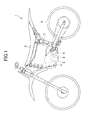
- Fig. 1 is an outer appearance side surface view of a vehicle 1 according to a preferred embodiment.
- the vehicle 1 is an electric motorcycle in which an electric motor 3 and an electric circuit 4, such as an engine control unit (ECU) or an inverter, are installed in a monocoque type frame 2, and which reduces a speed of a rotation output by the electric motor 3, by a speed reducer 5, and transfers the rotation output to a rear wheel 6.
- ECU engine control unit
- inverter an inverter
- a type of the vehicle 1 is not limited to a motorcycle, and may be another type of vehicle.
- the vehicle 1 is provided with a motor other than the electric motor 3, and may be a vehicle in a so-called hybrid type.
- the frame 2 is configured in a monocoque type here, but may use a pipe or a pressed frame other than the monocoque type.
- charging of the battery pack 7 is performed by detaching the battery pack from the vehicle 1.
- the battery pack 7 is simply detachable, that is, the battery pack 7 can be attached to and detached from the vehicle 1 without using any tool.
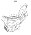
- Fig. 2 is a perspective view illustrating a structure of the vicinity of a battery pack accommodation portion 9 of the frame 2.
- the battery pack accommodation portion 9 is a box-shaped space which is open upward, and can be accessed from the outside by detaching the saddle 8 from the vehicle 1 and opening a lid 10 provided on an upper portion of the frame 2.
- the lid 10 can be opened by a simple method which does not use a tool, for example, by unfastening a latch 11 provided on the end portion of the lid 10.
- a plurality (two battery packs in the example of the drawing) of battery packs 7 is installed.
- a size and a weight of one battery pack 7 is appropriate for carrying by hand.
- the weight of the battery pack 7 is designed to be equal to or less than 10 kg, there is a case where the sufficient output and range can be obtained when the vehicle 1 travels by a single battery pack 7.
- as many as needed of the plurality of battery packs 7 are installed, and electric power is supplied to the vehicle 1 from each of the battery packs 7 at the same time when the vehicle 1 travels. According to this, it is possible to achieve both a convenience of carrying the battery pack 7 by hand and a guarantee of the necessary output and range.
- the common battery pack 7 is used in a plurality of types of vehicles, and as many as a number of the battery packs 7 that needed according to a required specification of the type of the vehicle. According to this, it is advantageous that it is possible to flexibly respond to various requirements without a necessity of revising the design of the battery pack 7 of every type of vehicle.
- the battery pack 7 is simply attached and detached, for example, in an event, such as a racing event, by preparing a charged reserve battery pack 7 and exchanging the battery pack 7 as necessary, it is possible to travel for a long period of time even at a place where there is no charging equipment.
- a handle 12 is provided on an upper surface of the battery pack 7. By pulling up the battery pack 7 by holding the handle 12, it is possible to detach the battery pack 7 from the vehicle 1 in an extremely simple manner. Attaching the battery pack 7 is as simple as detaching the battery pack 7.
- a term “battery pack” indicates a rechargeable battery module provided in a case, the battery module is provided with one or plurality, if necessary, of battery cells which is a member that charges electric power, so that the battery module can be handled easily and safely by itself.
- a rechargeable battery module having an energy density as high as possible.
- examples thereof include a lithium ion battery, a lithium ion capacitor, or the like.
- each of the battery packs 7 is easily detached from the vehicle, respectively charged, and individually exchanged.
- the BMS should be provided in every battery pack 7, and the charging state when the battery pack 7 is independently charged should be controlled.
- the battery pack 7 of the embodiment is the rechargeable battery and the BMS which are respectively accommodated in a case.
- Examples of a control of the charging state by the BMS when charging the battery pack 7 include: appropriately controlling a current, voltage, or both of these of the charging electric power which is input to every rechargeable battery module or battery cell (for example, a constant current control or a constant voltage control); and monitoring voltage or temperature for preventing an accident, damage, deterioration of life span due to an overcharge, or an increase in temperature, and appropriately blocking the charging electric power.
- Fig. 3 is an outer appearance perspective view of the battery pack 7.
- the entire battery pack 7 has a shape of a trunk case, and a heat sink 13 for cooling the BMS is exposed at a part of the battery pack 7.
- a battery pack side connection connector 14 for being electrically connected with the vehicle 1 is provided on a lower portion of the battery pack 7.
- the battery pack side connection connector 14 is in contact with and is electrically connected with a vehicle side connection connector provided in the battery pack accommodation portion 9.
- Fig. 4 is an exploded perspective view of the battery pack 7.
- the battery pack 7 accommodates a rechargeable battery module 16 and a BMS 17 in a case 15.
- a material of the case 15 may be an appropriate material, and may be formed by an arbitrary synthetic resin, a fiber-reinforced synthetic resin, and a metal. However, a material having shock resistance is preferable, and further, a material having an insulation property is preferable so that the high voltage maintained in the rechargeable battery module does not flow out to the outside when the case 15 is deformed or damaged. For example, in the embodiment, an ABS resin material is used.
- the case 15 is divided into two on a surface of a perpendicular direction, with respect to the battery pack 7.
- the BMS 17 brings the heat sink 13 into thermal contact with a field effect transistor (FET) and a substrate which stand close together, and dissipates the heat to the outside of the battery pack 7.
- FET field effect transistor
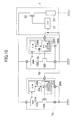
- Fig. 5 is a circuit diagram illustrating an electric system of the vehicle 1.
- Fig. 5 is a circuit diagram illustrating an electric system of the vehicle 1.
- suffixes A and B suffixes A and B, as necessary.
- a battery pack 7A and a battery pack 7B are of the same type, and are provided with the rechargeable battery module 16, the BMS 17, and further, a battery pack side switch 18 which is a switch that blocks the output to the outside from the rechargeable battery module 16, on the inside thereof.
- the battery pack side switch 18 is an analog switch, and specifically, the battery pack side switch 18 uses the FET.
- the battery pack side switch 18 is provided on a negative electrode side of the rechargeable battery module 16 in Fig. 5 , but may be provided on a positive electrode side of the rechargeable battery module 16 or may be provided on both sides.
- the BMS 17 includes: a cell monitor (C/M) 19 which is an integrated circuit (IC) for monitoring voltage or temperature of each cell included in the rechargeable battery module 16; and an M/C 20 which is an information processing circuit that controls the battery pack side switch 18 and the C/M 19 and communicates with a controller on the vehicle 1 side.
- the M/C 20 is a microcontroller.
- a specific configuration is arbitrary, and may be a general-purpose information processing apparatus, such as a computer made of a general central processing unit (CPU) and a memory, or a field programmable gate array (FPGA), and may be an information processing apparatus for a certain purpose, such as a digital signal processor (DSP), or an application specific integrated circuit (ASIC).
- the M/C 20 may be a single integrated circuit, may include a plurality of integrated circuits and peripheral circuits thereof, and may include a so-called communication controller.
- a rechargeable battery module 16A and a rechargeable battery module 16B are connected to each other in series in this example.
- an ECU 21 which functions as a vehicle side controller that communicates with the M/C 20 is provided on the vehicle 1 side.
- the ECU 21 is an information processing apparatus which electrically controls the entire vehicle 1, such as various types of electric components or meters provided in the vehicle 1, in addition to a rotation output of the electric motor 3 (refer to Fig. 1 ) according to an accelerator operation amount by an occupant or a state of the vehicle 1.
- the vehicle side controller which communicates with the M/C 20 may be provided to be separated from the ECU 21, and the vehicle side controller and the ECU 21 may be configured to perform information communication.
- the ECU 21 may also be an arbitrary information processing apparatus, and may be configured by the microcontroller, a general computer, the FPGA, the DSP, the ASIC, or the like.
- the electric power input from the battery pack 7 to the vehicle 1 is transferred to a load 23 via a vehicle side switch 22 which is a switch for blocking the input of the electric power.
- the load 23 is illustrated by adding impedance of each electric component provided in the vehicle 1, including the above-described electric motor 3.
- the vehicle side switch 22 is provided on a high potential side (that is, the battery pack 7 side) with respect to the load 23.
- the position is not particularly limited.
- the vehicle side switch 22 may be on a low potential side (that is, a ground side) of the load 23 and may be provided in the middle of the load 23, or a plurality of vehicle side switches 22 may be provided.
- a communication line 24 between the M/C 20 and the ECU 21 may be employed if at least one M/C 20 among the plurality of M/Cs 20 and the ECU 21 can communicate with each other.
- the communication line 24 which is based on a control area network (CAN) standard is used.
- CAN control area network
- LIN local interconnect network
- one of the plurality of battery packs 7 is set to be a master, and the rest of the battery packs 7 are set to be slaves.
- the BMS 17 of the battery pack 7 which is the master communicates with the BMS 17 of the slave, collects information of the battery pack 7 of the slave, and transmits the information by communicating with the ECU 21 representing the entire battery pack 7.
- the battery pack 7A is the master, and the battery pack 7B is the slave.
- a BMS 17A which is the master communicates with a BMS 17B which is the slave, collects information of the battery pack 7B, and transmits the information of the battery pack 7B to the ECU 21 together with information of the battery pack 7A.
- a master/slave discrimination portion 25 is provided in the battery pack 7, and it is determined whether the battery pack is the master or the slave, according to the installation state of the battery pack 7 in the vehicle 1.
- the master/slave discrimination portion 25 is realized by software which operates on the M/C 20
- the master/slave discrimination portion 25 is illustrated inside the M/C 20 in Fig. 5 .
- the master/slave discrimination portion 25 may be provided as a circuit separated from the M/C 20, or the master/slave discrimination portion 25 may be provided independently from the BMS 17.
- the installation state of the battery pack 7 in the vehicle 1 which is discriminated by the master/slave discrimination portion 25, indicates information which is obtained by distinguishing the battery pack 7 of itself with respect to other battery packs 7.
- a position of the battery pack 7 in the battery pack accommodation portion 9 (refer to Fig. 2 ) or an order of attaching the battery pack 7 to the vehicle 1, corresponds to the installation state which is referred to here.
- a master/slave designation contact point 26 is provided in the battery pack side connection connector 14, and a master/slave determination signal which designates whether the battery pack 7 is set to be the master or the slave is input.
- a specific signal which designates that the battery pack is the master is input to the master/slave designation contact point 26, and a signal which designates that the battery pack is the slave is input to the master/slave designation contact point 26 in another vehicle side connection connector.
- a master/slave designation contact point 26A of the battery pack 7A which is the master is connected to a battery GND, and a low potential is given as the master/slave determination signal.
- a master/slave discrimination portion 25A detects the low potential, and recognizes that the battery pack of the master/slave discrimination portion 25A itself is the master.
- a master/slave designation contact point 26B of the battery pack 7B which is the slave is not connected to the battery GND, and a high potential is given as the master/slave determination signal to be in a floating state.
- a master/slave discrimination portion 25B detects the high potential, and recognizes that the battery pack of the master/slave discrimination portion 25B itself is the slave.
- the discrimination by the master/slave discrimination portion 25 may be another method, for example, a method in which the battery pack recognizes itself as the master by being installed initially in the vehicle 1, and a method in which a mechanical switch that makes it possible to access to the battery pack 7 from the outside is provided and the mechanical switch is operated when the battery pack 7 is accommodated at a specific position of the battery pack accommodation portion 9 of the vehicle 1.
- the battery pack side switch 18 which is provided in the battery pack 7 is OFF (that is, a state where the output from the rechargeable battery module 16 is blocked) when the battery pack is not installed in the vehicle 1, and is ON when the vehicle 1 travels.
- the vehicle side switch 22 which is provided in the vehicle 1 is ON at least when the vehicle 1 travels, and the ON and OFF of the vehicle side switch 22 is controlled according to a main switch of the vehicle 1 in the embodiment. The ON and OFF of all of the switches are directly or indirectly controlled by a command from the ECU 21.
- the battery pack side switch 18 is controlled to be either ON or OFF by a signal from the outside of the battery pack 7. Accordingly, even when the plurality of battery packs 7 are used at the same time, it is possible to uniformly handle a presence or an absence of the output from each of the battery packs 7. In addition, when the battery pack 7 is detached from the vehicle 1, there is no difficulty in detecting the detachment of the battery pack 7 and automatically making the battery pack side switch 18 OFF.
- the control of the battery pack side switch 18 at that time may be performed by the BMS 17, or a dedicated circuit may be provided.
- the ECU 21 controls the switches to allow the vehicle side switch 22 to be ON. In other words, when the battery pack side switch 18 of any of the battery packs 7 is OFF, the vehicle side switch 22 is prohibited from being ON. The reasons thereof will be described by using Figs. 6 to 9 .
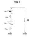
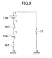
- Figs. 6 to 9 are views simplifying and illustrating the circuit diagram in Fig. 5 .
- a battery pack side switch 18A, a battery pack side switch 18B, and the vehicle side switch 22 are illustrated in a form of clarifying the ON and OFF states thereof.
- Fig. 6 illustrates a state where all of the battery pack side switch 18A, the battery pack side switch 18B, and the vehicle side switch 22 are ON.
- voltage between terminals of the rechargeable battery module 16 is +V
- a potential difference between both ends of the battery pack side switch 18A and the battery pack side switch 18B is zero
- a potential difference between both ends of the vehicle side switch 22 is 2V.
- an element which is used in the vehicle side switch 22 at least an element which has pressure resistance of 2V should be selected.
- Fig. 7 illustrates a state where all of the battery pack side switch 18A, the battery pack side switch 18B, and the vehicle side switch 22 are OFF. At this time, it is found that a voltage value in each place in the circuit is as illustrated in the drawing, and a potential difference between both ends of the battery pack side switch 18A is zero, but a potential difference between both ends of the battery pack side switch 18B and the vehicle side switch 22 is V. According to this, as an element which is used in the battery pack side switch 18, at least an element which has pressure resistance of V should be selected.
- a voltage value in each place in the circuit is as illustrated in the drawing, and a potential difference between both ends of the battery pack side switch 18A is 2V.
- a similar phenomenon occurs even when only the battery pack side switch 18B is OFF, and the battery pack side switch 18A and the vehicle side switch 22 are ON. In this case, the potential difference between both ends of the battery pack side switch 18B is 2V.
- the pressure resistance of the battery pack side switch 18 may be equal to or greater than 2V which is equivalent to that of the vehicle side switch 22, but the element having high pressure resistance is expensive, and causes an increase in cost of the battery pack 7.
- the similar phenomenon can occur even when the main switch is OFF as the vehicle 1 stops traveling, or the like.
- the battery pack side switch 18 of any of the battery packs 7 is OFF in a state where the vehicle side switch 22 is ON, states similar to those illustrated in Figs. 8 and 9 appear.
- the ECU 21 controls the battery pack side switch 18 to be allowed to be OFF.
- Fig. 10 is a modification example of the circuit diagram illustrated in Fig. 5 .
- the circuit illustrated here is an example of a case where the rechargeable battery module 16A and the rechargeable battery module 16B are connected to each other in parallel.
- Fig. 10 the same members as in the previous examples are given the same reference numerals, and repeated descriptions thereof will be omitted.
- each battery pack 7 is configured to supply electric power to the vehicle 1 at the same time when the vehicle 1 travels.
- the BMS 17 of the battery pack should be the master (be in a state where only the master exists).
- the BMS 17A is the master as the master/slave designation contact point 26A of the battery pack 7A is connected to the battery GND, when the battery pack 7 is used independently, the battery pack 7 should be installed on the battery pack 7A side of Fig. 10 .
Landscapes
- Engineering & Computer Science (AREA)
- Power Engineering (AREA)
- Transportation (AREA)
- Mechanical Engineering (AREA)
- Life Sciences & Earth Sciences (AREA)
- Sustainable Development (AREA)
- Sustainable Energy (AREA)
- Electric Propulsion And Braking For Vehicles (AREA)
- Charge And Discharge Circuits For Batteries Or The Like (AREA)
- Secondary Cells (AREA)
- Battery Mounting, Suspending (AREA)
Abstract
Description
- The present invention relates to a battery pack, a battery pack assembly, a vehicle and a method for controlling a battery pack assembly.
- In an electric vehicle or in a part of a so-called hybrid vehicle which is provided with both a motor and an electric motor, it is required that a rechargeable battery which charges electric power be installed and that the rechargeable battery be charged prior to traveling.
- In
JP 5-330465 A JP 5-330465 A - In
JP 5219992 B JP 5219992 B - When it is desired that the electric vehicle obtain sufficient output and range in traveling, a size of a battery becomes large and a weight of the battery becomes heavy, and thus, it is difficult to detach the battery from a vehicle and to carry the battery by hand. For this reason, as disclosed in the above-described related art, in general, a battery charging is performed by connecting the vehicle and a commercial power supply to each other in a state where the battery is installed in the vehicle.
- However, in the method, a restriction in which the vehicle should be parked in a parking lot where the commercial power supply is placed in order to charge the battery, is generated. This restriction causes a result in which a convenience of a light vehicle, such as a saddle type vehicle including a motorcycle, which can relatively freely select a parking place, is significantly damaged. In addition, here, the saddle type vehicle indicates a vehicle in a type in which a driver sits astride on a saddle, and includes various types of vehicles, such as a motorcycle, a three-wheeled or four-wheeled buggy which is referred to as an all terrain vehicle (ATV) or a recreational off-highway vehicle (ROV), a snowmobile, or an electric assist bicycle.
- It is the object of the present invention to provide battery pack, a battery pack assembly, a vehicle and a method for controlling a battery pack assembly wherein the battery pack can be easily handled.
- According to the present invention said object is solved by a battery pack having the features of
independent claim 1, a battery pack assembly having the features ofclaim 2, a vehicle having the features of claim 4, and a method for controlling a battery pack assembly having the features ofclaim 12. Preferred embodiments are laid down in the dependent claims. Accordingly, it is provided battery pack, a battery pack assembly, a vehicle and a method for controlling a battery pack assembly wherein the battery pack which can be simply detached from the vehicle, carried, and charged is installed. - The present teaching which is disclosed in the patent application has a various aspects, and an outline of the representative aspects is as follows.
- (1) According to an aspect, there is provided a vehicle which can install a plurality of detachable battery packs that accommodates a rechargeable battery module and a battery management system (BMS) in a case. In a state where the battery pack is installed in the vehicle, the BMS can perform information communication with another BMS, and one BMS is a master and can communicate with another BMS which is a slave and combine information of another battery pack. In a state where the battery pack is detached from the vehicle, a control of a charging state is independently performed by the BMS with respect to the rechargeable battery module.
- (2) In the aspect according to (1), the battery pack may be charged in a state of being detached from the vehicle.
- (3) In the aspect according to (1) or (2), the vehicle may further include a vehicle side controller. By the BMS which is the master, combined information of the battery pack may be transmitted to the vehicle side controller.
- (4) In the aspect according to any one of (1) to (3), the battery pack may further include a master/slave discrimination portion. The master/slave discrimination portion may determine whether the BMS related to the battery pack is the master or the slave, according to an installation state of the battery pack in the vehicle.
- (5) In the aspect according to (4), the battery pack may have a battery pack side connection connector for being electrically connected with the vehicle. In the battery pack side connection connector, a master/slave designation contact point, in which a master/slave determination signal for designating the BMS related to the battery pack as the master or the slave is input, may be included.
- (6) In the aspect according to any one of (1) to (5), the battery pack may have a battery pack side switch which blocks an output from the rechargeable battery module. The battery pack side switch may be controlled to be either ON or OFF by a signal from the outside.
- (7) In the aspect according to (6), the vehicle may have a vehicle side switch which blocks an input from the battery pack. The vehicle side switch may be allowed to be ON on the condition that all of the battery pack side switches are ON.
- (8) In the aspect according to (7), the battery pack side switch may be allowed to be OFF on the condition that the vehicle side switch is OFF.
- (9) According to another aspect, there is provided a battery pack including: a rechargeable battery module; a BMS; a case which accommodates the rechargeable battery module and the BMS; and a master/slave discrimination portion which determines whether the BMS is a master or a slave, according to an installation state in a vehicle. In a state where the battery pack is installed in the vehicle, the BMS can perform information communication with another BMS, and one BMS is the master and can communicate with another BMS which is the slave and can combine information of another battery pack. In a state where the battery pack is detached from the vehicle, a control of a charging state is independently performed by the BMS with respect to the rechargeable battery module.
-
-
Fig. 1 is an outer appearance side surface view of a vehicle according to a preferred embodiment. -
Fig. 2 is a perspective view illustrating a structure of the vicinity of a battery pack accommodation portion of a frame. -
Fig. 3 is an outer appearance perspective view of a battery pack. -
Fig. 4 is an exploded perspective view of the battery pack. -
Fig. 5 is a circuit diagram illustrating an electric system of the vehicle. -
Fig. 6 is a view simplifying and illustrating the circuit diagram inFig. 5 . -
Fig. 7 is a view simplifying and illustrating the circuit diagram inFig. 5 . -
Fig. 8 is a view simplifying and illustrating the circuit diagram inFig. 5 . -
Fig. 9 is a view simplifying and illustrating the circuit diagram inFig. 5 . -
Fig. 10 is a modification example of the circuit diagram illustrated inFig. 5 . - Hereinafter, a preferred embodiment will be described with reference to the drawings.
-
Fig. 1 is an outer appearance side surface view of avehicle 1 according to a preferred embodiment. Here, thevehicle 1 is an electric motorcycle in which anelectric motor 3 and an electric circuit 4, such as an engine control unit (ECU) or an inverter, are installed in amonocoque type frame 2, and which reduces a speed of a rotation output by theelectric motor 3, by aspeed reducer 5, and transfers the rotation output to arear wheel 6. - In addition, a type of the
vehicle 1 is not limited to a motorcycle, and may be another type of vehicle. In addition, thevehicle 1 is provided with a motor other than theelectric motor 3, and may be a vehicle in a so-called hybrid type. Furthermore, theframe 2 is configured in a monocoque type here, but may use a pipe or a pressed frame other than the monocoque type. - A
battery pack 7 which is installed in thevehicle 1 and is a power source of theelectric motor 3, is accommodated in a box-shaped battery pack accommodation portion which is configured by theframe 2, and is disposed right below asaddle 8. In the embodiment, charging of thebattery pack 7 is performed by detaching the battery pack from thevehicle 1. For this reason, thebattery pack 7 is simply detachable, that is, thebattery pack 7 can be attached to and detached from thevehicle 1 without using any tool. -
Fig. 2 is a perspective view illustrating a structure of the vicinity of a battery pack accommodation portion 9 of theframe 2. The battery pack accommodation portion 9 is a box-shaped space which is open upward, and can be accessed from the outside by detaching thesaddle 8 from thevehicle 1 and opening alid 10 provided on an upper portion of theframe 2. In addition, thelid 10 can be opened by a simple method which does not use a tool, for example, by unfastening alatch 11 provided on the end portion of thelid 10. - As illustrated in the drawing, a plurality (two battery packs in the example of the drawing) of
battery packs 7 is installed. A size and a weight of onebattery pack 7 is appropriate for carrying by hand. For example, since the weight of thebattery pack 7 is designed to be equal to or less than 10 kg, there is a case where the sufficient output and range can be obtained when thevehicle 1 travels by asingle battery pack 7. Here, as described in the embodiment, as many as needed of the plurality ofbattery packs 7 are installed, and electric power is supplied to thevehicle 1 from each of thebattery packs 7 at the same time when thevehicle 1 travels. According to this, it is possible to achieve both a convenience of carrying thebattery pack 7 by hand and a guarantee of the necessary output and range. - In addition, in this configuration, the
common battery pack 7 is used in a plurality of types of vehicles, and as many as a number of thebattery packs 7 that needed according to a required specification of the type of the vehicle. According to this, it is advantageous that it is possible to flexibly respond to various requirements without a necessity of revising the design of thebattery pack 7 of every type of vehicle. In addition, since thebattery pack 7 is simply attached and detached, for example, in an event, such as a racing event, by preparing a chargedreserve battery pack 7 and exchanging thebattery pack 7 as necessary, it is possible to travel for a long period of time even at a place where there is no charging equipment. - On an upper surface of the
battery pack 7, ahandle 12 is provided. By pulling up thebattery pack 7 by holding thehandle 12, it is possible to detach thebattery pack 7 from thevehicle 1 in an extremely simple manner. Attaching thebattery pack 7 is as simple as detaching thebattery pack 7. - Here, a term "battery pack" indicates a rechargeable battery module provided in a case, the battery module is provided with one or plurality, if necessary, of battery cells which is a member that charges electric power, so that the battery module can be handled easily and safely by itself. In order to supply the sufficient electric power in practical traveling of the
vehicle 1, it is desirable to select a rechargeable battery module having an energy density as high as possible. At present, examples thereof include a lithium ion battery, a lithium ion capacitor, or the like. However, it is found that a high level of voltage and current control of the rechargeable battery in the type is necessary while charging and discharging, and a control circuit which is called a BMS is used in order to control the charging and discharging, recognize an accurate remaining charging capacity, and perform a regenerative control. - In the embodiment, each of the battery packs 7 is easily detached from the vehicle, respectively charged, and individually exchanged. For this reason, the BMS should be provided in every
battery pack 7, and the charging state when thebattery pack 7 is independently charged should be controlled. In other words, thebattery pack 7 of the embodiment is the rechargeable battery and the BMS which are respectively accommodated in a case. Examples of a control of the charging state by the BMS when charging thebattery pack 7 include: appropriately controlling a current, voltage, or both of these of the charging electric power which is input to every rechargeable battery module or battery cell (for example, a constant current control or a constant voltage control); and monitoring voltage or temperature for preventing an accident, damage, deterioration of life span due to an overcharge, or an increase in temperature, and appropriately blocking the charging electric power. -
Fig. 3 is an outer appearance perspective view of thebattery pack 7. Theentire battery pack 7 has a shape of a trunk case, and aheat sink 13 for cooling the BMS is exposed at a part of thebattery pack 7. In addition, although not illustrated in the drawing, a battery packside connection connector 14 for being electrically connected with thevehicle 1 is provided on a lower portion of thebattery pack 7. When thebattery pack 7 is accommodated in the battery pack accommodation portion 9 (refer toFig. 2 ), the battery packside connection connector 14 is in contact with and is electrically connected with a vehicle side connection connector provided in the battery pack accommodation portion 9. -
Fig. 4 is an exploded perspective view of thebattery pack 7. Thebattery pack 7 accommodates arechargeable battery module 16 and aBMS 17 in acase 15. A material of thecase 15 may be an appropriate material, and may be formed by an arbitrary synthetic resin, a fiber-reinforced synthetic resin, and a metal. However, a material having shock resistance is preferable, and further, a material having an insulation property is preferable so that the high voltage maintained in the rechargeable battery module does not flow out to the outside when thecase 15 is deformed or damaged. For example, in the embodiment, an ABS resin material is used. Thecase 15 is divided into two on a surface of a perpendicular direction, with respect to thebattery pack 7. - In order to dissipate the heat while operating, the
BMS 17 brings theheat sink 13 into thermal contact with a field effect transistor (FET) and a substrate which stand close together, and dissipates the heat to the outside of thebattery pack 7. -
Fig. 5 is a circuit diagram illustrating an electric system of thevehicle 1. In addition, since twobattery packs 7 are installed in thevehicle 1 of the embodiment, in order to distinguish each of the battery packs 7, reference numerals are respectively given suffixes A and B, as necessary. - A
battery pack 7A and abattery pack 7B are of the same type, and are provided with therechargeable battery module 16, theBMS 17, and further, a battery pack side switch 18 which is a switch that blocks the output to the outside from therechargeable battery module 16, on the inside thereof. In addition, here, the battery pack side switch 18 is an analog switch, and specifically, the battery pack side switch 18 uses the FET. In addition, the battery pack side switch 18 is provided on a negative electrode side of therechargeable battery module 16 inFig. 5 , but may be provided on a positive electrode side of therechargeable battery module 16 or may be provided on both sides. - The
BMS 17 includes: a cell monitor (C/M) 19 which is an integrated circuit (IC) for monitoring voltage or temperature of each cell included in therechargeable battery module 16; and an M/C 20 which is an information processing circuit that controls the battery pack side switch 18 and the C/M 19 and communicates with a controller on thevehicle 1 side. Here, the M/C 20 is a microcontroller. However, a specific configuration is arbitrary, and may be a general-purpose information processing apparatus, such as a computer made of a general central processing unit (CPU) and a memory, or a field programmable gate array (FPGA), and may be an information processing apparatus for a certain purpose, such as a digital signal processor (DSP), or an application specific integrated circuit (ASIC). In addition, the M/C 20 may be a single integrated circuit, may include a plurality of integrated circuits and peripheral circuits thereof, and may include a so-called communication controller. - A
rechargeable battery module 16A and arechargeable battery module 16B are connected to each other in series in this example. - In addition, an
ECU 21 which functions as a vehicle side controller that communicates with the M/C 20 is provided on thevehicle 1 side. Here, theECU 21 is an information processing apparatus which electrically controls theentire vehicle 1, such as various types of electric components or meters provided in thevehicle 1, in addition to a rotation output of the electric motor 3 (refer toFig. 1 ) according to an accelerator operation amount by an occupant or a state of thevehicle 1. However, the vehicle side controller which communicates with the M/C 20 may be provided to be separated from theECU 21, and the vehicle side controller and theECU 21 may be configured to perform information communication. TheECU 21 may also be an arbitrary information processing apparatus, and may be configured by the microcontroller, a general computer, the FPGA, the DSP, the ASIC, or the like. - The electric power input from the
battery pack 7 to thevehicle 1 is transferred to aload 23 via avehicle side switch 22 which is a switch for blocking the input of the electric power. Theload 23 is illustrated by adding impedance of each electric component provided in thevehicle 1, including the above-describedelectric motor 3. InFig. 5 , thevehicle side switch 22 is provided on a high potential side (that is, thebattery pack 7 side) with respect to theload 23. However, the position is not particularly limited. Thevehicle side switch 22 may be on a low potential side (that is, a ground side) of theload 23 and may be provided in the middle of theload 23, or a plurality of vehicle side switches 22 may be provided. - A
communication line 24 between the M/C 20 and theECU 21 may be employed if at least one M/C 20 among the plurality of M/Cs 20 and theECU 21 can communicate with each other. However, in the embodiment, thecommunication line 24 which is based on a control area network (CAN) standard is used. Certainly, a communication standard other than the CAN, for example, a local interconnect network (LIN), may be used. - However, as illustrated in
Fig. 5 , in a state where the plurality ofbattery packs 7 are provided and the plurality of M/Cs 20 and theECU 21 can communicate with each other, it is not possible to discriminate whichbattery pack 7 includes the M/C 20 that communicates with theECU 21, and it is not possible to exactly understand not only a state of each of the battery packs 7A and 7B but also a state of theentire battery pack 7. - Here, in the embodiment, one of the plurality of battery packs 7 is set to be a master, and the rest of the battery packs 7 are set to be slaves. The
BMS 17 of thebattery pack 7 which is the master communicates with theBMS 17 of the slave, collects information of thebattery pack 7 of the slave, and transmits the information by communicating with theECU 21 representing theentire battery pack 7. - In the example illustrated in
Fig. 5 , thebattery pack 7A is the master, and thebattery pack 7B is the slave. For this reason, aBMS 17A which is the master communicates with aBMS 17B which is the slave, collects information of thebattery pack 7B, and transmits the information of thebattery pack 7B to theECU 21 together with information of thebattery pack 7A. - At this time, how to determine which
battery pack 7 is the master among the plurality of battery packs is a problem. In the most simple manner, preparing two types of thebattery pack 7 including thebattery pack 7 which functions as the master and thebattery pack 7 which functions as the slave can be considered. According to the present teaching, it is not necessary to exclude the configuration. However, it cannot be said that the configuration is always preferable since there are several problems that a cost increases when the plurality of types ofbattery pack 7 is prepared, or that a human error (for example, there is a possibility that a plurality of battery packs for the master is installed, or that only the battery pack for the slave is installed) is likely to occur when installing thebattery pack 7. - Here, in the embodiment, a master/slave discrimination portion 25 is provided in the
battery pack 7, and it is determined whether the battery pack is the master or the slave, according to the installation state of thebattery pack 7 in thevehicle 1. In addition, in the embodiment, since the master/slave discrimination portion 25 is realized by software which operates on the M/C 20, the master/slave discrimination portion 25 is illustrated inside the M/C 20 inFig. 5 . However, the master/slave discrimination portion 25 may be provided as a circuit separated from the M/C 20, or the master/slave discrimination portion 25 may be provided independently from theBMS 17. - Here, the installation state of the
battery pack 7 in thevehicle 1 which is discriminated by the master/slave discrimination portion 25, indicates information which is obtained by distinguishing thebattery pack 7 of itself with respect to other battery packs 7. For example, a position of thebattery pack 7 in the battery pack accommodation portion 9 (refer toFig. 2 ) or an order of attaching thebattery pack 7 to thevehicle 1, corresponds to the installation state which is referred to here. - In the embodiment, in the
battery pack 7, a master/slave designation contact point 26 is provided in the battery packside connection connector 14, and a master/slave determination signal which designates whether thebattery pack 7 is set to be the master or the slave is input. In one of the vehicle side connection connectors which is provided in the battery pack accommodation portion 9 of thevehicle 1, a specific signal which designates that the battery pack is the master is input to the master/slave designation contact point 26, and a signal which designates that the battery pack is the slave is input to the master/slave designation contact point 26 in another vehicle side connection connector. - In the example of
Fig. 5 , a master/slavedesignation contact point 26A of thebattery pack 7A which is the master is connected to a battery GND, and a low potential is given as the master/slave determination signal. A master/slave discrimination portion 25A detects the low potential, and recognizes that the battery pack of the master/slave discrimination portion 25A itself is the master. - Meanwhile, a master/slave
designation contact point 26B of thebattery pack 7B which is the slave is not connected to the battery GND, and a high potential is given as the master/slave determination signal to be in a floating state. A master/slave discrimination portion 25B detects the high potential, and recognizes that the battery pack of the master/slave discrimination portion 25B itself is the slave. - In addition, the discrimination by the master/slave discrimination portion 25 may be another method, for example, a method in which the battery pack recognizes itself as the master by being installed initially in the
vehicle 1, and a method in which a mechanical switch that makes it possible to access to thebattery pack 7 from the outside is provided and the mechanical switch is operated when thebattery pack 7 is accommodated at a specific position of the battery pack accommodation portion 9 of thevehicle 1. - However, the battery pack side switch 18 which is provided in the
battery pack 7 is OFF (that is, a state where the output from therechargeable battery module 16 is blocked) when the battery pack is not installed in thevehicle 1, and is ON when thevehicle 1 travels. In addition, thevehicle side switch 22 which is provided in thevehicle 1 is ON at least when thevehicle 1 travels, and the ON and OFF of thevehicle side switch 22 is controlled according to a main switch of thevehicle 1 in the embodiment. The ON and OFF of all of the switches are directly or indirectly controlled by a command from theECU 21. - In other words, the battery pack side switch 18 is controlled to be either ON or OFF by a signal from the outside of the
battery pack 7. Accordingly, even when the plurality ofbattery packs 7 are used at the same time, it is possible to uniformly handle a presence or an absence of the output from each of the battery packs 7. In addition, when thebattery pack 7 is detached from thevehicle 1, there is no difficulty in detecting the detachment of thebattery pack 7 and automatically making the battery pack side switch 18 OFF. The control of the battery pack side switch 18 at that time may be performed by theBMS 17, or a dedicated circuit may be provided. - Here, when the
battery pack 7 is installed in thevehicle 1, only on the condition that the battery pack side switches 18 of all of the battery packs 7 are ON, theECU 21 controls the switches to allow thevehicle side switch 22 to be ON. In other words, when the battery pack side switch 18 of any of the battery packs 7 is OFF, thevehicle side switch 22 is prohibited from being ON. The reasons thereof will be described by usingFigs. 6 to 9 . -
Figs. 6 to 9 are views simplifying and illustrating the circuit diagram inFig. 5 . Here, a batterypack side switch 18A, a batterypack side switch 18B, and thevehicle side switch 22 are illustrated in a form of clarifying the ON and OFF states thereof. -
Fig. 6 illustrates a state where all of the batterypack side switch 18A, the batterypack side switch 18B, and thevehicle side switch 22 are ON. Here, if voltage between terminals of therechargeable battery module 16 is +V, it is found that a voltage value in each place in the circuit is as illustrated in the drawing, a potential difference between both ends of the batterypack side switch 18A and the batterypack side switch 18B is zero, and a potential difference between both ends of thevehicle side switch 22 is 2V. According to this, as an element which is used in thevehicle side switch 22, at least an element which has pressure resistance of 2V should be selected. -
Fig. 7 illustrates a state where all of the batterypack side switch 18A, the batterypack side switch 18B, and thevehicle side switch 22 are OFF. At this time, it is found that a voltage value in each place in the circuit is as illustrated in the drawing, and a potential difference between both ends of the batterypack side switch 18A is zero, but a potential difference between both ends of the batterypack side switch 18B and thevehicle side switch 22 is V. According to this, as an element which is used in the battery pack side switch 18, at least an element which has pressure resistance of V should be selected. - However, as illustrated in
Fig. 8 , considering that only the batterypack side switch 18A is OFF and the batterypack side switch 18B and thevehicle side switch 22 are ON, a voltage value in each place in the circuit is as illustrated in the drawing, and a potential difference between both ends of the batterypack side switch 18A is 2V. As illustrated inFig. 9 , a similar phenomenon occurs even when only the batterypack side switch 18B is OFF, and the batterypack side switch 18A and thevehicle side switch 22 are ON. In this case, the potential difference between both ends of the batterypack side switch 18B is 2V. - In order to prevent damage to the battery pack side switch 18 due to the potential difference between both ends, the pressure resistance of the battery pack side switch 18 may be equal to or greater than 2V which is equivalent to that of the
vehicle side switch 22, but the element having high pressure resistance is expensive, and causes an increase in cost of thebattery pack 7. - Here, only on the condition that the battery pack side switches 18 of all of the battery packs 7 are ON, if the
ECU 21 controls thevehicle side switch 22 to be allowed to be ON, it is possible to avoid the states illustrated inFigs. 8 and9 , and to use a switch having pressure resistance which is at least V as the battery pack side switch 18. Accordingly, while preventing damage to the battery pack side switch 18 due to the potential difference between both ends, it is possible to use an element having a minimum level of pressure resistance as the battery pack side switch 18, and to reduce a manufacturing cost of thebattery pack 7. - The similar phenomenon can occur even when the main switch is OFF as the
vehicle 1 stops traveling, or the like. In other words, when the battery pack side switch 18 of any of the battery packs 7 is OFF in a state where thevehicle side switch 22 is ON, states similar to those illustrated inFigs. 8 and9 appear. For this reason, with respect to the battery pack side switch 18, only on the condition that thevehicle side switch 22 is OFF, theECU 21 controls the battery pack side switch 18 to be allowed to be OFF. -
Fig. 10 is a modification example of the circuit diagram illustrated inFig. 5 . The circuit illustrated here is an example of a case where therechargeable battery module 16A and therechargeable battery module 16B are connected to each other in parallel. In addition, inFig. 10 , the same members as in the previous examples are given the same reference numerals, and repeated descriptions thereof will be omitted. - In this manner, there is no problem even when the plurality of
battery packs 7 are used in parallel. Furthermore, there is no problem even when the plural battery packs 7 are used in series and in parallel at the same time. In every case, theBMS 17 of onebattery pack 7 among the plurality of battery packs 7 is the master. In addition, eachbattery pack 7 is configured to supply electric power to thevehicle 1 at the same time when thevehicle 1 travels. - Furthermore, as illustrated in
Fig. 10 , when the battery packs 7 are used in parallel, it is possible to use thebattery pack 7 independently. However, even in this case, for convenience of transmitting the information of the installedbattery pack 7 to theECU 21, theBMS 17 of the battery pack should be the master (be in a state where only the master exists). In the example ofFig. 10 , since theBMS 17A is the master as the master/slavedesignation contact point 26A of thebattery pack 7A is connected to the battery GND, when thebattery pack 7 is used independently, thebattery pack 7 should be installed on thebattery pack 7A side ofFig. 10 .
Claims (13)
- A battery pack, comprising:a rechargeable battery module (16,16A,16B);a battery management system (17, 17A, 17B);a case (15) which accommodates the rechargeable battery module (16,16A,16B) and the battery management system (17,17A,17B); andwherein, in a state where the battery pack (7,7A,7B) is installed in the vehicle, the battery management system (17,17A,17B) is configured to perform information communication with another battery management system (17,17A,17B), wherein the battery management system (17,17A,17B) is configured to be controlled as a master and configured to communicate with another battery management system (17,17A,17B) which is a slave, andthe battery management system (17,17A,17B) is configured to be controlled as a slave and configured to communicate with another battery management system (17,17A,17B) which is a master,andwherein, in a state where the battery pack (7,7A,7B) is detached from the vehicle, the battery management system (17,17A,17B) is configured to control of a charging state independently performed with respect to the rechargeable battery module (16,16A,16B).
- A battery pack assembly comprising at least two battery packs (7,7A,7B) according to claim 1, wherein one battery management system (17,17A,17B) is configured to be controlled as the master, configured to communicate with another battery management system (17,17A,17B) which is a slave, and can combine information of another battery pack (7,7A,7B), and
the other battery management system (17,17A,17B) is configured to be controlled as the slave, configured to communicate with another battery management system (17,17A,17B) which is a master. - A battery pack assembly comprising at least two battery packs (7,7A,7B) according to claim 2, wherein battery packs (7,7A,7B) are provided within a battery pack accommodation portion (9).
- A vehicle configured to accommodate a battery pack assembly according to claim 2 or 3 as a power source for driving the vehicle.
- A vehicle according to claim 4, wherein the battery pack (7,7A,7B) is configured to be charged in a state of being detached from the vehicle.
- A vehicle according to claim 4 or 5, further comprising:a vehicle side controller (21) configured to receive combined information of the battery pack (7,7A,7B) by the battery management system (17,17A,17B) which is the master, wherein combined information of the battery pack (7, 7A, 7B) is transmitted to the vehicle side controller (21).
- A vehicle according to at least one of the claims 4 to 6, wherein the battery pack (7,7A,7B) further includes a master/slave discrimination portion (25), and
wherein the master/slave discrimination portion (25) is configured to determine whether the battery management system (17,17A,17B) related to the battery pack (7, 7A, 7B) is the master or the slave, according to an installation state of the battery pack (7,7A,7B) in the vehicle. - A vehicle according to claim 7, wherein the battery pack (7,7A,7B) has a battery pack side connection connector (14) for being electrically connected with the vehicle, and wherein, in the battery pack side connection connector (14), a master/slave designation contact point (26,26A,26B), in which a master/slave determination signal for designating the battery management system (17,17A,17B) related to the battery pack (7, 7A, 7B) as the master or the slave is input, is included.
- A vehicle according at least one of the claims 4 to 8, wherein the battery pack (7, 7A, 7B) has a battery pack side switch (18,18A,18B) configured to block an output from the rechargeable battery module (16,16A,16B), and
wherein the battery pack side switch (18,18A,18B) is configured to be controlled to be either ON or OFF by a signal from the outside. - A vehicle according to claim 9, wherein the vehicle has a vehicle side switch (22) configured to block an input from the battery pack (7,7A,7B), and
wherein the vehicle side switch (22) is configured to be allowed to be ON on the condition that all of the battery pack side switches (18,18A,18B) are ON. - A vehicle according to claim 10, wherein the battery pack side switch (18, 8A, 8B) is configured to be allowed to be OFF on the condition that the vehicle side switch (22) is OFF.
- A method for controlling a battery pack assembly of least two battery packs (7,7A,7B) according to claim 1, comprising the steps:determine whether the battery management system (17,17A,17B) is a master or a slave, according to an detected installation state in a vehicle,wherein, in a state where the battery pack (7, 7A, 7B) is installed in the vehicle, performing information communication of one battery management system (17, 17A, 17B) with another battery management system (17, 17A, 17B),controlling one battery management system (17,17A,17B) as a master andcommunicating with the other battery management system (17, 17A, 17B) which is a slave, andcontrolling the other battery management system (17,17A,17B) as a slave and communicating with another battery management system (17,17A,17B) which is a master and combine information of another battery pack (7, 7A, 7B).
- A method for controlling a battery pack assembly according to claim 12, further comprising:charging the battery pack (7,7A,7B) in a state of being detached from the vehicle.
Applications Claiming Priority (1)
| Application Number | Priority Date | Filing Date | Title |
|---|---|---|---|
| JP2013230723A JP6245947B2 (en) | 2013-11-06 | 2013-11-06 | Vehicle and battery pack |
Publications (3)
| Publication Number | Publication Date |
|---|---|
| EP2902248A2 true EP2902248A2 (en) | 2015-08-05 |
| EP2902248A3 EP2902248A3 (en) | 2016-01-20 |
| EP2902248B1 EP2902248B1 (en) | 2016-10-12 |
Family
ID=51951575
Family Applications (1)
| Application Number | Title | Priority Date | Filing Date |
|---|---|---|---|
| EP14192016.5A Active EP2902248B1 (en) | 2013-11-06 | 2014-11-06 | Vehicle and battery pack and method for controlling a battery pack assembly |
Country Status (3)
| Country | Link |
|---|---|
| US (1) | US9421872B2 (en) |
| EP (1) | EP2902248B1 (en) |
| JP (1) | JP6245947B2 (en) |
Cited By (1)
| Publication number | Priority date | Publication date | Assignee | Title |
|---|---|---|---|---|
| CN107168289A (en) * | 2017-06-02 | 2017-09-15 | 重庆大学 | A kind of entire car controller of pure electronic equation motorcycle race |
Families Citing this family (17)
| Publication number | Priority date | Publication date | Assignee | Title |
|---|---|---|---|---|
| EP3372439A4 (en) | 2015-11-02 | 2018-11-14 | Yamaha Hatsudoki Kabushiki Kaisha | Mobile body using removable battery |
| JP2017161311A (en) * | 2016-03-08 | 2017-09-14 | 株式会社東芝 | Storage battery device |
| WO2018151110A1 (en) * | 2017-02-14 | 2018-08-23 | ヤマハ発動機株式会社 | Power supply circuit |
| DE102017211468A1 (en) * | 2017-07-05 | 2019-01-10 | Robert Bosch Gmbh | Master control unit for a battery system |
| KR102182054B1 (en) * | 2018-02-12 | 2020-11-23 | (주)우영에너지홀딩스 | Apparatus for switching battery pack of vehicle and method thereof |
| CN109263514B (en) * | 2018-09-11 | 2023-05-05 | 众声物联(天津)科技有限公司 | Device and method for upgrading Internet of things power vehicle by using traditional power vehicle |
| KR101974807B1 (en) * | 2018-10-02 | 2019-08-28 | (주)티에스식스티즈 | Smart slave battery management system and method for battery management thereof |
| DE102020126158B4 (en) * | 2020-10-06 | 2026-04-09 | Smart Battery Solutions GmbH | Intelligent electrical connector for interchangeable battery units of an electric vehicle |
| CN112622647B (en) * | 2020-12-28 | 2022-12-27 | 戴红斌 | New energy automobile power supply method |
| EP4292846A1 (en) | 2021-02-09 | 2023-12-20 | Honda Motor Co., Ltd. | Traveling vehicle |
| US12485981B2 (en) | 2021-03-24 | 2025-12-02 | Polaris Industries Inc. | Electric recreational vehicle |
| IT202100011432A1 (en) * | 2021-05-05 | 2022-11-05 | Piaggio & C Spa | Electric or hybrid ride-on vehicle including a removable rechargeable battery and a battery locking device |
| JP7488228B2 (en) * | 2021-07-28 | 2024-05-21 | 矢崎総業株式会社 | Vehicle control unit and vehicle control system |
| JP7823389B2 (en) * | 2021-12-28 | 2026-03-04 | 株式会社椿本チエイン | Power supply device and power supply system |
| DE102022112582A1 (en) * | 2022-05-19 | 2023-11-23 | Next.E.Go Mobile SE | BATTERY FOR A MOTOR VEHICLE, MOTOR VEHICLE AND METHOD FOR CHARGING SUCH A BATTERY |
| CN115626085B (en) * | 2022-10-25 | 2025-11-07 | 重庆芯虹智能装备有限责任公司 | Control method, system, device and medium for quick-change battery pack of electric automobile |
| KR20260008400A (en) | 2024-07-09 | 2026-01-16 | 주식회사 엠디엠 | Battery operating system |
Citations (2)
| Publication number | Priority date | Publication date | Assignee | Title |
|---|---|---|---|---|
| JPH05330465A (en) | 1992-03-30 | 1993-12-14 | Honda Motor Co Ltd | Electric vehicle and battery unit for electric vehicle |
| JP5219992B2 (en) | 2009-12-24 | 2013-06-26 | 本田技研工業株式会社 | Electric vehicle power supply device |
Family Cites Families (26)
| Publication number | Priority date | Publication date | Assignee | Title |
|---|---|---|---|---|
| US5477936A (en) | 1991-10-19 | 1995-12-26 | Honda Giken Kogyo Kabushiki Kaisha | Electric motor vehicle and battery unit for electric motor vehicle |
| US5543248A (en) | 1995-02-17 | 1996-08-06 | Globe-Union Inc. | Thermal stabilization shield for storage batteries |
| JP2988918B1 (en) * | 1998-08-31 | 1999-12-13 | 三菱電機株式会社 | Monitoring system for multiple battery packs in electronic equipment |
| JP3405526B2 (en) * | 1999-04-02 | 2003-05-12 | エヌイーシートーキン栃木株式会社 | Multiple battery pack power supply |
| JP3890168B2 (en) * | 1999-08-03 | 2007-03-07 | 株式会社東京アールアンドデー | Electric device and charging / discharging method of battery unit thereof |
| JP2001114157A (en) | 1999-10-19 | 2001-04-24 | Yamaha Motor Co Ltd | Battery assembly structure for electric vehicles |
| JP3939546B2 (en) | 2001-12-06 | 2007-07-04 | パナソニック・イーブイ・エナジー株式会社 | Battery power device for electric vehicle |
| JP4350531B2 (en) | 2004-01-08 | 2009-10-21 | 本田技研工業株式会社 | Electric vehicle |
| JP2005280656A (en) | 2004-03-31 | 2005-10-13 | Honda Motor Co Ltd | Electric vehicle |
| GB2422717B (en) | 2005-02-01 | 2007-11-14 | Intelligent Energy Ltd | Detachable fuel cell power unit for vehicle applications |
| DE102008032044A1 (en) | 2008-07-08 | 2010-02-11 | Ktm Sportmotorcycle Ag | Electrically operated vehicle with a driver's seat |
| JP2010036791A (en) | 2008-08-07 | 2010-02-18 | Yamaha Motor Co Ltd | Saddle riding type vehicle |
| JP5593894B2 (en) | 2009-07-30 | 2014-09-24 | スズキ株式会社 | A battery pack to be attached to and detached from an electric vehicle and an electric vehicle including the battery pack |
| WO2011163244A2 (en) | 2010-06-23 | 2011-12-29 | Johnson Controls - Saft Advanced Power Solutions Llc | Battery power source device |
| JP5328736B2 (en) | 2010-08-31 | 2013-10-30 | 本田技研工業株式会社 | Control device for electric motorcycle |
| CN103140414B (en) | 2010-09-30 | 2015-12-09 | 铃木株式会社 | two-wheeled electric vehicle |
| JP5595227B2 (en) | 2010-10-29 | 2014-09-24 | 本田技研工業株式会社 | Electric motorcycle |
| JP5527183B2 (en) * | 2010-12-01 | 2014-06-18 | 株式会社デンソー | Battery control system, charge / discharge control ECU |
| TWM415829U (en) | 2011-04-28 | 2011-11-11 | Formosa Electronic Ind Inc | Battery with detachable power supply |
| KR101473385B1 (en) * | 2011-05-31 | 2014-12-16 | 주식회사 엘지화학 | Power storage apparatus, power storage system comprising the same, and method of assembling power storage system using the same |
| GB2526005B (en) | 2011-09-02 | 2016-04-06 | Pag Ltd | Battery management system, method and battery |
| JP5853025B2 (en) | 2011-10-28 | 2016-02-09 | 川崎重工業株式会社 | Straddle-type electric vehicle |
| JP2013109976A (en) | 2011-11-21 | 2013-06-06 | Yamaha Motor Co Ltd | Battery pack and saddle-ride vehicle having the same |
| JP5894814B2 (en) | 2012-02-20 | 2016-03-30 | 本田技研工業株式会社 | Electric vehicle power supply |
| US9263901B2 (en) * | 2012-05-19 | 2016-02-16 | Tesla Motors, Inc. | Secondary service port for high voltage battery packs |
| JP5165164B1 (en) * | 2012-08-10 | 2013-03-21 | パナソニック株式会社 | Electric vehicle |
-
2013
- 2013-11-06 JP JP2013230723A patent/JP6245947B2/en active Active
-
2014
- 2014-11-05 US US14/533,478 patent/US9421872B2/en active Active
- 2014-11-06 EP EP14192016.5A patent/EP2902248B1/en active Active
Patent Citations (2)
| Publication number | Priority date | Publication date | Assignee | Title |
|---|---|---|---|---|
| JPH05330465A (en) | 1992-03-30 | 1993-12-14 | Honda Motor Co Ltd | Electric vehicle and battery unit for electric vehicle |
| JP5219992B2 (en) | 2009-12-24 | 2013-06-26 | 本田技研工業株式会社 | Electric vehicle power supply device |
Cited By (2)
| Publication number | Priority date | Publication date | Assignee | Title |
|---|---|---|---|---|
| CN107168289A (en) * | 2017-06-02 | 2017-09-15 | 重庆大学 | A kind of entire car controller of pure electronic equation motorcycle race |
| CN107168289B (en) * | 2017-06-02 | 2019-10-01 | 重庆大学 | A kind of entire car controller of pure electric vehicle equation motorcycle race |
Also Published As
| Publication number | Publication date |
|---|---|
| US9421872B2 (en) | 2016-08-23 |
| EP2902248A3 (en) | 2016-01-20 |
| JP2015091200A (en) | 2015-05-11 |
| US20150127206A1 (en) | 2015-05-07 |
| EP2902248B1 (en) | 2016-10-12 |
| JP6245947B2 (en) | 2017-12-13 |
Similar Documents
| Publication | Publication Date | Title |
|---|---|---|
| EP2902248B1 (en) | Vehicle and battery pack and method for controlling a battery pack assembly | |
| CN103250320B (en) | The battery charge controller of motor vehicle | |
| US20170021739A1 (en) | Straddled electric vehicle, and charging system for straddled electric vehicle | |
| US20060152189A1 (en) | Vehicle charging, monitoring and control systems for electric and hybrid electric vehicles | |
| CN111278723B (en) | Saddle-ride type electric vehicle | |
| WO2016112411A1 (en) | Circuitry harness and pass through for lead wires of a battery module | |
| JP2011139572A (en) | Charging coupler and charging controller | |
| JP2012050198A (en) | Meter display device for electric vehicle | |
| CN104395134B (en) | Charging control device for electric vehicles | |
| CN110832725A (en) | Power storage device, vehicle, and motorcycle | |
| US20160141572A1 (en) | Liquid trap for a lithium ion battery system | |
| CN102346237A (en) | Device for calculating the remaining capacity of a battery | |
| CN111278722B (en) | Saddle-ride type two-wheeled electric vehicle | |
| US10840562B2 (en) | Energy storage system, monitoring unit for energy storage device, and method of monitoring energy storage device | |
| CN116234718A (en) | Systems and methods for managing heterogeneous battery modules | |
| CN114475332A (en) | Multi-charging interface monitoring and protection system for electric vehicle | |
| CN111148689B (en) | straddle-type electric vehicle | |
| JP2013519352A (en) | Electric power supply system for vehicles | |
| KR20250002415A (en) | Intelligent battery system, components for intelligent battery system, methods for manufacturing and operating intelligent battery system and components thereof | |
| CN111148688B (en) | Saddle-ride type electric vehicle | |
| KR102624683B1 (en) | Battery system and control method thereof | |
| US20230322103A1 (en) | Cable assembly for electric vehicle to electric vehicle charging | |
| CN116872733B (en) | Integrated whole vehicle control system of low-speed electric vehicle and control method thereof | |
| TWI832046B (en) | Straddle-type vehicle battery pack and straddle-type vehicle | |
| CN215244441U (en) | Electric vehicle controller with charging and discharging management function and electric vehicle |
Legal Events
| Date | Code | Title | Description |
|---|---|---|---|
| PUAI | Public reference made under article 153(3) epc to a published international application that has entered the european phase |
Free format text: ORIGINAL CODE: 0009012 |
|
| 17P | Request for examination filed |
Effective date: 20141106 |
|
| AK | Designated contracting states |
Kind code of ref document: A2 Designated state(s): AL AT BE BG CH CY CZ DE DK EE ES FI FR GB GR HR HU IE IS IT LI LT LU LV MC MK MT NL NO PL PT RO RS SE SI SK SM TR |
|
| AX | Request for extension of the european patent |
Extension state: BA ME |
|
| PUAL | Search report despatched |
Free format text: ORIGINAL CODE: 0009013 |
|
| AK | Designated contracting states |
Kind code of ref document: A3 Designated state(s): AL AT BE BG CH CY CZ DE DK EE ES FI FR GB GR HR HU IE IS IT LI LT LU LV MC MK MT NL NO PL PT RO RS SE SI SK SM TR |
|
| AX | Request for extension of the european patent |
Extension state: BA ME |
|
| RIC1 | Information provided on ipc code assigned before grant |
Ipc: B60L 3/00 20060101ALI20151214BHEP Ipc: H01M 10/00 20060101ALI20151214BHEP Ipc: B60L 11/18 20060101ALI20151214BHEP Ipc: B60L 11/00 20060101AFI20151214BHEP Ipc: H02J 7/00 20060101ALI20151214BHEP |
|
| 17P | Request for examination filed |
Effective date: 20160317 |
|
| RBV | Designated contracting states (corrected) |
Designated state(s): AL AT BE BG CH CY CZ DE DK EE ES FI FR GB GR HR HU IE IS IT LI LT LU LV MC MK MT NL NO PL PT RO RS SE SI SK SM TR |
|
| GRAP | Despatch of communication of intention to grant a patent |
Free format text: ORIGINAL CODE: EPIDOSNIGR1 |
|
| RIC1 | Information provided on ipc code assigned before grant |
Ipc: B60L 11/00 20060101AFI20160429BHEP Ipc: H01M 10/00 20060101ALI20160429BHEP Ipc: B60L 3/00 20060101ALI20160429BHEP Ipc: B60L 11/18 20060101ALI20160429BHEP Ipc: H02J 7/00 20060101ALI20160429BHEP |
|
| INTG | Intention to grant announced |
Effective date: 20160602 |
|
| GRAS | Grant fee paid |
Free format text: ORIGINAL CODE: EPIDOSNIGR3 |
|
| GRAA | (expected) grant |
Free format text: ORIGINAL CODE: 0009210 |
|
| AK | Designated contracting states |
Kind code of ref document: B1 Designated state(s): AL AT BE BG CH CY CZ DE DK EE ES FI FR GB GR HR HU IE IS IT LI LT LU LV MC MK MT NL NO PL PT RO RS SE SI SK SM TR |
|
| REG | Reference to a national code |
Ref country code: GB Ref legal event code: FG4D |
|
| REG | Reference to a national code |
Ref country code: CH Ref legal event code: EP |
|
| REG | Reference to a national code |
Ref country code: AT Ref legal event code: REF Ref document number: 836170 Country of ref document: AT Kind code of ref document: T Effective date: 20161015 |
|
| REG | Reference to a national code |
Ref country code: IE Ref legal event code: FG4D |
|
| REG | Reference to a national code |
Ref country code: DE Ref legal event code: R096 Ref document number: 602014004197 Country of ref document: DE |
|
| REG | Reference to a national code |
Ref country code: NL Ref legal event code: FP |
|
| REG | Reference to a national code |
Ref country code: LT Ref legal event code: MG4D |
|
| PG25 | Lapsed in a contracting state [announced via postgrant information from national office to epo] |
Ref country code: LV Free format text: LAPSE BECAUSE OF FAILURE TO SUBMIT A TRANSLATION OF THE DESCRIPTION OR TO PAY THE FEE WITHIN THE PRESCRIBED TIME-LIMIT Effective date: 20161012 Ref country code: BE Free format text: LAPSE BECAUSE OF NON-PAYMENT OF DUE FEES Effective date: 20161130 |
|
| REG | Reference to a national code |
Ref country code: AT Ref legal event code: MK05 Ref document number: 836170 Country of ref document: AT Kind code of ref document: T Effective date: 20161012 |
|
| PG25 | Lapsed in a contracting state [announced via postgrant information from national office to epo] |
Ref country code: GR Free format text: LAPSE BECAUSE OF FAILURE TO SUBMIT A TRANSLATION OF THE DESCRIPTION OR TO PAY THE FEE WITHIN THE PRESCRIBED TIME-LIMIT Effective date: 20170113 Ref country code: SE Free format text: LAPSE BECAUSE OF FAILURE TO SUBMIT A TRANSLATION OF THE DESCRIPTION OR TO PAY THE FEE WITHIN THE PRESCRIBED TIME-LIMIT Effective date: 20161012 Ref country code: NO Free format text: LAPSE BECAUSE OF FAILURE TO SUBMIT A TRANSLATION OF THE DESCRIPTION OR TO PAY THE FEE WITHIN THE PRESCRIBED TIME-LIMIT Effective date: 20170112 Ref country code: LT Free format text: LAPSE BECAUSE OF FAILURE TO SUBMIT A TRANSLATION OF THE DESCRIPTION OR TO PAY THE FEE WITHIN THE PRESCRIBED TIME-LIMIT Effective date: 20161012 |
|
| PG25 | Lapsed in a contracting state [announced via postgrant information from national office to epo] |
Ref country code: FI Free format text: LAPSE BECAUSE OF FAILURE TO SUBMIT A TRANSLATION OF THE DESCRIPTION OR TO PAY THE FEE WITHIN THE PRESCRIBED TIME-LIMIT Effective date: 20161012 Ref country code: BE Free format text: LAPSE BECAUSE OF FAILURE TO SUBMIT A TRANSLATION OF THE DESCRIPTION OR TO PAY THE FEE WITHIN THE PRESCRIBED TIME-LIMIT Effective date: 20161012 Ref country code: IS Free format text: LAPSE BECAUSE OF FAILURE TO SUBMIT A TRANSLATION OF THE DESCRIPTION OR TO PAY THE FEE WITHIN THE PRESCRIBED TIME-LIMIT Effective date: 20170212 Ref country code: ES Free format text: LAPSE BECAUSE OF FAILURE TO SUBMIT A TRANSLATION OF THE DESCRIPTION OR TO PAY THE FEE WITHIN THE PRESCRIBED TIME-LIMIT Effective date: 20161012 Ref country code: PL Free format text: LAPSE BECAUSE OF FAILURE TO SUBMIT A TRANSLATION OF THE DESCRIPTION OR TO PAY THE FEE WITHIN THE PRESCRIBED TIME-LIMIT Effective date: 20161012 Ref country code: AT Free format text: LAPSE BECAUSE OF FAILURE TO SUBMIT A TRANSLATION OF THE DESCRIPTION OR TO PAY THE FEE WITHIN THE PRESCRIBED TIME-LIMIT Effective date: 20161012 Ref country code: RS Free format text: LAPSE BECAUSE OF FAILURE TO SUBMIT A TRANSLATION OF THE DESCRIPTION OR TO PAY THE FEE WITHIN THE PRESCRIBED TIME-LIMIT Effective date: 20161012 Ref country code: HR Free format text: LAPSE BECAUSE OF FAILURE TO SUBMIT A TRANSLATION OF THE DESCRIPTION OR TO PAY THE FEE WITHIN THE PRESCRIBED TIME-LIMIT Effective date: 20161012 Ref country code: PT Free format text: LAPSE BECAUSE OF FAILURE TO SUBMIT A TRANSLATION OF THE DESCRIPTION OR TO PAY THE FEE WITHIN THE PRESCRIBED TIME-LIMIT Effective date: 20170213 |
|
| REG | Reference to a national code |
Ref country code: DE Ref legal event code: R097 Ref document number: 602014004197 Country of ref document: DE |
|
| PG25 | Lapsed in a contracting state [announced via postgrant information from national office to epo] |
Ref country code: MC Free format text: LAPSE BECAUSE OF FAILURE TO SUBMIT A TRANSLATION OF THE DESCRIPTION OR TO PAY THE FEE WITHIN THE PRESCRIBED TIME-LIMIT Effective date: 20161012 Ref country code: CZ Free format text: LAPSE BECAUSE OF FAILURE TO SUBMIT A TRANSLATION OF THE DESCRIPTION OR TO PAY THE FEE WITHIN THE PRESCRIBED TIME-LIMIT Effective date: 20161012 Ref country code: SK Free format text: LAPSE BECAUSE OF FAILURE TO SUBMIT A TRANSLATION OF THE DESCRIPTION OR TO PAY THE FEE WITHIN THE PRESCRIBED TIME-LIMIT Effective date: 20161012 Ref country code: RO Free format text: LAPSE BECAUSE OF FAILURE TO SUBMIT A TRANSLATION OF THE DESCRIPTION OR TO PAY THE FEE WITHIN THE PRESCRIBED TIME-LIMIT Effective date: 20161012 Ref country code: DK Free format text: LAPSE BECAUSE OF FAILURE TO SUBMIT A TRANSLATION OF THE DESCRIPTION OR TO PAY THE FEE WITHIN THE PRESCRIBED TIME-LIMIT Effective date: 20161012 Ref country code: EE Free format text: LAPSE BECAUSE OF FAILURE TO SUBMIT A TRANSLATION OF THE DESCRIPTION OR TO PAY THE FEE WITHIN THE PRESCRIBED TIME-LIMIT Effective date: 20161012 |
|
| PLBE | No opposition filed within time limit |
Free format text: ORIGINAL CODE: 0009261 |
|
| STAA | Information on the status of an ep patent application or granted ep patent |
Free format text: STATUS: NO OPPOSITION FILED WITHIN TIME LIMIT |
|
| REG | Reference to a national code |
Ref country code: IE Ref legal event code: MM4A |
|
| REG | Reference to a national code |
Ref country code: FR Ref legal event code: ST Effective date: 20170731 |
|
| PG25 | Lapsed in a contracting state [announced via postgrant information from national office to epo] |
Ref country code: SM Free format text: LAPSE BECAUSE OF FAILURE TO SUBMIT A TRANSLATION OF THE DESCRIPTION OR TO PAY THE FEE WITHIN THE PRESCRIBED TIME-LIMIT Effective date: 20161012 Ref country code: IT Free format text: LAPSE BECAUSE OF FAILURE TO SUBMIT A TRANSLATION OF THE DESCRIPTION OR TO PAY THE FEE WITHIN THE PRESCRIBED TIME-LIMIT Effective date: 20161012 Ref country code: BG Free format text: LAPSE BECAUSE OF FAILURE TO SUBMIT A TRANSLATION OF THE DESCRIPTION OR TO PAY THE FEE WITHIN THE PRESCRIBED TIME-LIMIT Effective date: 20170112 |
|
| 26N | No opposition filed |
Effective date: 20170713 |
|
| PG25 | Lapsed in a contracting state [announced via postgrant information from national office to epo] |
Ref country code: LU Free format text: LAPSE BECAUSE OF NON-PAYMENT OF DUE FEES Effective date: 20161130 |
|
| PG25 | Lapsed in a contracting state [announced via postgrant information from national office to epo] |
Ref country code: FR Free format text: LAPSE BECAUSE OF NON-PAYMENT OF DUE FEES Effective date: 20161212 |
|
| PG25 | Lapsed in a contracting state [announced via postgrant information from national office to epo] |
Ref country code: IE Free format text: LAPSE BECAUSE OF NON-PAYMENT OF DUE FEES Effective date: 20161106 Ref country code: SI Free format text: LAPSE BECAUSE OF FAILURE TO SUBMIT A TRANSLATION OF THE DESCRIPTION OR TO PAY THE FEE WITHIN THE PRESCRIBED TIME-LIMIT Effective date: 20161012 |
|
| PG25 | Lapsed in a contracting state [announced via postgrant information from national office to epo] |
Ref country code: HU Free format text: LAPSE BECAUSE OF FAILURE TO SUBMIT A TRANSLATION OF THE DESCRIPTION OR TO PAY THE FEE WITHIN THE PRESCRIBED TIME-LIMIT; INVALID AB INITIO Effective date: 20141106 |
|
| PG25 | Lapsed in a contracting state [announced via postgrant information from national office to epo] |
Ref country code: MK Free format text: LAPSE BECAUSE OF FAILURE TO SUBMIT A TRANSLATION OF THE DESCRIPTION OR TO PAY THE FEE WITHIN THE PRESCRIBED TIME-LIMIT Effective date: 20161012 Ref country code: CY Free format text: LAPSE BECAUSE OF FAILURE TO SUBMIT A TRANSLATION OF THE DESCRIPTION OR TO PAY THE FEE WITHIN THE PRESCRIBED TIME-LIMIT Effective date: 20161012 |
|
| PG25 | Lapsed in a contracting state [announced via postgrant information from national office to epo] |
Ref country code: CH Free format text: LAPSE BECAUSE OF NON-PAYMENT OF DUE FEES Effective date: 20171130 Ref country code: LI Free format text: LAPSE BECAUSE OF NON-PAYMENT OF DUE FEES Effective date: 20171130 |
|
| PG25 | Lapsed in a contracting state [announced via postgrant information from national office to epo] |
Ref country code: MT Free format text: LAPSE BECAUSE OF NON-PAYMENT OF DUE FEES Effective date: 20161106 |
|
| PG25 | Lapsed in a contracting state [announced via postgrant information from national office to epo] |
Ref country code: TR Free format text: LAPSE BECAUSE OF FAILURE TO SUBMIT A TRANSLATION OF THE DESCRIPTION OR TO PAY THE FEE WITHIN THE PRESCRIBED TIME-LIMIT Effective date: 20161012 |
|
| GBPC | Gb: european patent ceased through non-payment of renewal fee |
Effective date: 20181106 |
|
| PG25 | Lapsed in a contracting state [announced via postgrant information from national office to epo] |
Ref country code: GB Free format text: LAPSE BECAUSE OF NON-PAYMENT OF DUE FEES Effective date: 20181106 |
|
| PG25 | Lapsed in a contracting state [announced via postgrant information from national office to epo] |
Ref country code: AL Free format text: LAPSE BECAUSE OF FAILURE TO SUBMIT A TRANSLATION OF THE DESCRIPTION OR TO PAY THE FEE WITHIN THE PRESCRIBED TIME-LIMIT Effective date: 20161012 |
|
| P01 | Opt-out of the competence of the unified patent court (upc) registered |
Effective date: 20230527 |
|
| PGFP | Annual fee paid to national office [announced via postgrant information from national office to epo] |
Ref country code: NL Payment date: 20251119 Year of fee payment: 12 |
|
| PGFP | Annual fee paid to national office [announced via postgrant information from national office to epo] |
Ref country code: DE Payment date: 20251119 Year of fee payment: 12 |