EP2902206A1 - Printhead arrangement on a printbar beam member - Google Patents
Printhead arrangement on a printbar beam member Download PDFInfo
- Publication number
- EP2902206A1 EP2902206A1 EP14275019.9A EP14275019A EP2902206A1 EP 2902206 A1 EP2902206 A1 EP 2902206A1 EP 14275019 A EP14275019 A EP 14275019A EP 2902206 A1 EP2902206 A1 EP 2902206A1
- Authority
- EP
- European Patent Office
- Prior art keywords
- printbar
- longitudinal axis
- printhead
- printheads
- beam member
- Prior art date
- Legal status (The legal status is an assumption and is not a legal conclusion. Google has not performed a legal analysis and makes no representation as to the accuracy of the status listed.)
- Granted
Links
- XUIMIQQOPSSXEZ-UHFFFAOYSA-N Silicon Chemical compound [Si] XUIMIQQOPSSXEZ-UHFFFAOYSA-N 0.000 claims description 13
- 229910052710 silicon Inorganic materials 0.000 claims description 13
- 239000010703 silicon Substances 0.000 claims description 13
- 238000000034 method Methods 0.000 claims description 8
- 238000010586 diagram Methods 0.000 description 4
- 230000000712 assembly Effects 0.000 description 3
- 238000000429 assembly Methods 0.000 description 3
- 230000001419 dependent effect Effects 0.000 description 3
- 239000012530 fluid Substances 0.000 description 1
Images


Classifications
-
- B—PERFORMING OPERATIONS; TRANSPORTING
- B41—PRINTING; LINING MACHINES; TYPEWRITERS; STAMPS
- B41J—TYPEWRITERS; SELECTIVE PRINTING MECHANISMS, i.e. MECHANISMS PRINTING OTHERWISE THAN FROM A FORME; CORRECTION OF TYPOGRAPHICAL ERRORS
- B41J2/00—Typewriters or selective printing mechanisms characterised by the printing or marking process for which they are designed
- B41J2/005—Typewriters or selective printing mechanisms characterised by the printing or marking process for which they are designed characterised by bringing liquid or particles selectively into contact with a printing material
- B41J2/01—Ink jet
- B41J2/135—Nozzles
- B41J2/14—Structure thereof only for on-demand ink jet heads
- B41J2/1433—Structure of nozzle plates
-
- B—PERFORMING OPERATIONS; TRANSPORTING
- B41—PRINTING; LINING MACHINES; TYPEWRITERS; STAMPS
- B41J—TYPEWRITERS; SELECTIVE PRINTING MECHANISMS, i.e. MECHANISMS PRINTING OTHERWISE THAN FROM A FORME; CORRECTION OF TYPOGRAPHICAL ERRORS
- B41J2/00—Typewriters or selective printing mechanisms characterised by the printing or marking process for which they are designed
- B41J2/005—Typewriters or selective printing mechanisms characterised by the printing or marking process for which they are designed characterised by bringing liquid or particles selectively into contact with a printing material
- B41J2/01—Ink jet
- B41J2/135—Nozzles
- B41J2/145—Arrangement thereof
- B41J2/155—Arrangement thereof for line printing
-
- B—PERFORMING OPERATIONS; TRANSPORTING
- B41—PRINTING; LINING MACHINES; TYPEWRITERS; STAMPS
- B41J—TYPEWRITERS; SELECTIVE PRINTING MECHANISMS, i.e. MECHANISMS PRINTING OTHERWISE THAN FROM A FORME; CORRECTION OF TYPOGRAPHICAL ERRORS
- B41J2202/00—Embodiments of or processes related to ink-jet or thermal heads
- B41J2202/01—Embodiments of or processes related to ink-jet heads
- B41J2202/20—Modules
Definitions
- a printhead assembly may include a printbar beam member and a plurality of printheads.
- the printheads may be spaced apart from each other along the printbar beam member.
- the printbar beam member may extend across a print zone and a width of media.
- the printheads may apply fluid onto media to form images thereon.
- Printers such as page wide presses may include printhead assemblies that include a printbar beam member and a plurality of printheads.
- the printbar beam member extends across a print zone including a width of media.
- the printheads may include a printhead native resolution.
- the printheads may be arranged on the printbar beam member in a manner that the printbar native resolution may be the same as a respective printhead native resolution.
- printheads may be positioned in a manner that a row of nozzles are perpendicular to a media printing axis.
- a maximum resolution of a printed image printed by a printhead during one printing cycle may be limited to the printhead native resolution of the printhead. Accordingly, multiple printing cycles may be used to print an image on media having a resolution greater than the printhead native resolution. Increased printing cycles, however, may decrease printing throughput.
- a printhead assembly includes a printbar beam member having a printbar longitudinal axis and a plurality of printheads.
- Each printhead includes a printhead longitudinal axis and a row of nozzles arranged parallel to the printhead longitudinal axis.
- the plurality of printheads are arranged on the printbar beam member in a manner in which each respective printhead longitudinal axis is traverse to the printbar longitudinal axis. Further, a portion of respective rows of the nozzles of adjacent printheads overlap each other with respect to the printbar longitudinal axis. Additionally, nozzles of the adjacent printheads are not arranged along a same line perpendicular to the printbar longitudinal axis. Accordingly, a printbar native resolution across the printbar beam member with the plurality of printheads disposed thereon is greater than a printhead native resolution of a respective printhead.
- such a printhead arrangement may extend possible native resolutions which in turn can allow utilizing even higher print resolutions. Additionally, by increasing the printbar's native resolution, the number of print cycles is reduced and therefore throughput is increased. Also, less printheads per print cycles and printed region may be needed due to the increased printbar native resolution resulting in a reduction of cross-print placement errors and print artifacts.
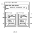
- FIG. 1 is a block diagram illustrating a printhead assembly according to an example.
- a printhead assembly 100 includes a printbar beam member 10 and a plurality of printheads 11.
- the printbar beam member 10 includes a printbar longitudinal axis 10a.
- Each printhead 11 includes a printhead longitudinal axis 11a and a row 12 of nozzles 13 arranged parallel to the printhead longitudinal axis 11 a.
- the plurality of printheads 11 are arranged on the printbar beam member 10 in a manner in which each respective printhead longitudinal axis 11a is traverse to the printbar longitudinal axis 10a.
- nozzles 13 of adjacent printheads 11 overlap each other with respect to the printbar longitudinal axis 10a. Additionally, nozzles 13 of the adjacent printheads 11 are not arranged along a same line perpendicular to the printbar longitudinal axis 10a.
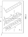
- FIG. 2 is a schematic view illustrating a printhead assembly according to an example.
- FIG. 3 is a schematic view illustrating the printhead assembly of FIG. 2 according to an example.
- the printhead assembly 200 includes the printbar beam member 10 and the plurality of printheads 11 as previously discussed with respect to FIG. 1 .
- Each printhead 11 may include a printhead native resolution, a printhead longitudinal axis 11a, and a row 12 of nozzles 13.
- the printhead native resolution is dependent on a pitch of respective nozzles 13 and a tilt angle ⁇ which corresponds to distance between nozzles of a nozzle arrangement projection on a longitudinal axis thereof.
- the resolution of an image printed on media by the respective printhead 11 may be dependent on the respective printhead native resolution.
- the printbar beam member 10 may include a printbar native resolution and a printbar longitudinal axis 10a extending in a cross-printing direction d c .
- the printbar native resolution corresponds to the distance between nozzles 13 arranged across the printbar beam member 10 in a respective direction d c .
- the resolution of an image printed on media by a respective printbar beam member 10 may be dependent on the respective printbar native resolution.
- the printbar native resolution across the printbar beam member 10 with the plurality of printheads 11 disposed thereon is greater than a printhead native resolution of a respective printhead 11.
- the plurality of printheads 11 may be arranged on the printbar beam member 10 in a manner in which each respective printhead longitudinal axis 11a is traverse to the printbar longitudinal axis 10a. That is, each respective printhead longitudinal axis 11a forms a tilt angle with the printbar longitudinal axis 10a.
- the printheads 11 are disposed on the printbar beam member 10 in a slanted (e.g., tilted) manner.
- each respective printhead longitudinal axis 11 a traverse to the printbar longitudinal axis 10a may form the tilt angle ⁇ therewith in a range from 5 degrees to 85 degrees including, for example, a range of about 60 degrees to about 71 degrees.
- a respective printhead 11 is arranged on the printbar beam member 10 in a slanted manner with respect to the printbar longitudinal axis 10a and its printhead longitudinal axis 11a being traverse to the printbar longitudinal axis 10a at a tilt angle of about 60 degrees. Consequently, an effective distance d between the nozzles 13 of the row 12 of nozzles 13 with respect to the printbar longitudinal axis 10a is half the distance (e.g. 0.5d) between nozzles 13' of a row 12' of nozzles 13' of a printhead 11' having a printhead longitudinal axis 11a' parallel to the printbar longitudinal axis 10a.
- the printhead native resolution of the printhead 11 is greater by arranging it in a slanted manner rather than in a non-slanted manner.
- a portion of respective rows 12 of the nozzles 13 of adjacent printheads 11 may overlap each other with respect to the printbar longitudinal axis 10a. Further, nozzles 13 of the adjacent printheads 11 are not arranged along a same line perpendicular 27 to the printbar longitudinal axis 10a. For example, at least a portion of the row 12 of nozzles 13 of one of the adjacent printheads 11 is below a portion of the row of nozzles 13 of another adjacent printhead 11 with respect to a perpendicular direction of the printbar longitudinal axis 10a.
- respective nozzles of the overlapping portions of the rows 12 of nozzles 13 are offset from each other with respect to respective lines 27 perpendicular to the printbar longitudinal axis 10a.
- the respective nozzles 13 may be positioned to enable the printbar native resolution across the printbar beam member 10 with the plurality of printheads 11 disposed to be greater than a printhead native resolution of a respective printhead 11.
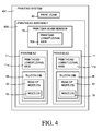
- FIG. 4 is a block diagram illustrating a printing system according to an example.
- a printing system 401 includes a print zone 45 and a printhead assembly 400.
- the print zone 45 may receive a media, for example to be printed on.
- the printhead assembly 400 includes a printbar beam member 10 and a plurality of printheads 41.
- the printbar beam member 10 includes a printbar longitudinal axis 10a, for example, extending across the print zone 45 in a cross-printing direction.
- Each printhead 41 includes a printhead longitudinal axis 11a and a plurality of silicon dies 46 arranged thereon.
- the plurality of printheads 41 are arranged on the printbar beam member 10 in a manner in which each respective printhead longitudinal axis 11 a is traverse to the printbar longitudinal axis 10a.
- Each silicon die 46 includes a row 12 of nozzles 13 arranged parallel to the respective printhead longitudinal axis 11 a.
- the respective silicon dies 46 on each printhead 41 are arranged in an offset arrangement with respect to each other.
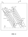
- FIG. 5 is a schematic view illustrating a printing system according to an example.
- FIG. 6 is a schematic view illustrating a printhead assembly of the printing system of FIG. 5 according to an example.
- the printing system 401 includes the print zone 45 and the printhead assembly 400 as previously discussed with respect to FIG. 4 .
- the print zone 45 may receive a media 48, for example, to be printed on.
- the printhead assembly 400 includes a printbar beam member 10 and a plurality of printheads 41.
- the printbar beam member 10 includes a printbar longitudinal axis 10a, for example, extending across the print zone 45 in a cross-printing direction d c .
- Each printhead 41 includes a printhead longitudinal axis 11a and a plurality of silicon dies 46 arranged thereon.
- each silicon die 46 includes a row 12 of nozzles 13 arranged parallel to the respective printhead longitudinal axis 11 a.
- the respective silicon dies 46 on each printhead 41 are arranged in an offset arrangement with respect to each other.
- the respective silicon dies 46 are offset from each other by a predetermined distance do.
- the predetermined distance do may be based on an amount of tilt angle ⁇ that the respective printhead longitudinal axis 11a forms with the printbar longitudinal axis 10a.
- respective nozzles 13 of adjacent printheads 41 are not arranged on a same line 27 perpendicular to the printbar longitudinal axis 10a.
- the plurality of printheads 41 are arranged on the printbar beam member 10 in a manner in which each respective printhead longitudinal axis 11 a is traverse to the printbar longitudinal axis 10a. That is, each respective printhead longitudinal axis 11 a forms a tilt angle ⁇ with the printbar longitudinal axis 10a.
- the printheads 11 are disposed on the printbar beam member 10 in a slanted manner.
- each respective printhead longitudinal axis 11a traverse to the printbar longitudinal axis 10a may form a tilt angle ⁇ therewith in a range from about 60 degrees to about 71 degrees.
- a respective printhead longitudinal axis 11 a may form a tilt angle ⁇ with the printbar longitudinal axis of about 60 degrees.
- the predetermined distance do of silicon dies offset from each other may be based on an amount of tilt angle that the respective printhead longitudinal axis forms with the printbar longitudinal axis.
- adjacent silicon dies 46 of a respective printhead 11 may be offset from each other by an offset distance do of about 2.4287 mm, for example, based on the printhead longitudinal axis 11 a forming a tilt angle ⁇ of about 60 degrees with the printbar longitudinal axis 10a.
- Such an arrangement may extend the span of possible native resolutions which in turn can allow utilizing even higher print resolutions.
- a printbar native resolution across the printbar beam member 10 with the plurality of printheads 41 disposed thereon is greater than a printhead native resolution of a respective printhead 41.
- the printbar native resolution across the printbar beam member 10 is at least double the respective printhead native resolution of the respective printhead 41.
- the printbar native resolution across the printbar beam member 10 is at least four times the respective printhead native resolution of the respective printhead 41.
- the printheads 41 may be arranged such that the printhead longitudinal axis 10a forms a tilt angle ⁇ of about 60 degrees with the printbar longitudinal axis 10a, and nozzles 13 of adjacent printheads 11 may be interweaved with each other with respect to a respective direction. For example, portions of rows 12 of nozzles 13 of adjacent printheads 11 may overlap each other with respective to the printbar longitudinal axis 10a.
- the plurality of printheads are inkjet printheads. A different color of ink may be ejected through each row 12 of nozzles 13 of a respective printhead 41. For example, each one of the different color ink is selected from at least one from the group consisting of black, cyan, magenta and yellow.
- FIG. 7 is a flowchart illustrating a method of establishing a printbar native resolution across a printbar beam member having a plurality of printheads greater than a printhead native resolution of a respective printhead according to an example.
- the assemblies and/or system implementing the method may be those described in relation to the printhead assemblies 100, 200, and 400 and printing system 401 of FIGS. 1-6 .
- the plurality of printheads are provided in which each printhead includes a printhead longitudinal axis and a plurality of rows of nozzles offset from each other by a predetermined distance and parallel to the respective printhead longitudinal axis.
- the predetermined distance is based on an amount of tilt angle that the respective printhead longitudinal axis forms with the printbar longitudinal axis.
- the plurality of printheads are arranged along the printbar beam member having a printbar longitudinal axis in a manner in which each respective printhead longitudinal axis is traverse to the printbar longitudinal axis.
- the plurality of printheads are arranged along the printbar beam member in a manner that a portion of respective rows of the nozzles of adjacent printheads overlap each other with respect to the printbar longitudinal axis without respective nozzles of the adjacent printheads positioned on a same line perpendicular to the printbar longitudinal axis.
- the plurality of printheads may be arranged along the printbar beam member to at least double the respective printhead native resolution of the respective printhead.
- arranging the plurality of printheads may include arranging the printheads such that each respective printhead longitudinal axis forms a tilt angle with the printbar longitudinal axis in a range from 5 degrees to 85 degrees including, for example, a range of about 60 degrees to about 70.5 degrees.
- each block may represent a module, segment, or portion of code that includes one or more executable instructions to implement the specified logical function(s).
- each block may represent a circuit or a number of interconnected circuits to implement the specified logical function(s).
- FIG. 7 illustrates a specific order of execution, the order of execution may differ from that which is depicted. For example, the order of execution of two or more blocks may be rearranged relative to the order illustrated. Also, two or more blocks illustrated in succession in FIG. 7 may be executed concurrently or with partial concurrence. All such variations are within the scope of the present disclosure.
Abstract
Description
- A printhead assembly may include a printbar beam member and a plurality of printheads. The printheads may be spaced apart from each other along the printbar beam member. The printbar beam member may extend across a print zone and a width of media. The printheads may apply fluid onto media to form images thereon.
- Non-limiting examples are described in the following description, read with reference to the figures attached hereto and do not limit the scope of the claims. Dimensions of components and features illustrated in the figures are chosen primarily for convenience and clarity of presentation and are not necessarily to scale. Referring to the attached figures:
-
FIG. 1 is a block diagram illustrating a printhead assembly according to an example. -
FIG. 2 is a schematic view illustrating a printhead assembly according to an example. -
FIG. 3 is a schematic view illustrating the printhead assembly ofFIG. 2 according to an example. -
FIG. 4 is a block diagram illustrating a printing system according to an example. -
FIG. 5 is a schematic view illustrating the printing system ofFIG. 4 according to an example. -
FIG. 6 is a schematic view illustrating a printhead assembly of the printing system ofFIG. 5 according to an example. -
FIG. 7 is a flowchart illustrating a method of establishing a printbar native resolution across a printbar beam member having a plurality of printheads greater than a printhead native resolution of a respective printhead according to an example. - Printers such as page wide presses may include printhead assemblies that include a printbar beam member and a plurality of printheads. The printbar beam member extends across a print zone including a width of media. The printheads may include a printhead native resolution. The printheads may be arranged on the printbar beam member in a manner that the printbar native resolution may be the same as a respective printhead native resolution. In general, printheads may be positioned in a manner that a row of nozzles are perpendicular to a media printing axis. A maximum resolution of a printed image printed by a printhead during one printing cycle may be limited to the printhead native resolution of the printhead. Accordingly, multiple printing cycles may be used to print an image on media having a resolution greater than the printhead native resolution. Increased printing cycles, however, may decrease printing throughput.
- In examples, a printhead assembly includes a printbar beam member having a printbar longitudinal axis and a plurality of printheads. Each printhead includes a printhead longitudinal axis and a row of nozzles arranged parallel to the printhead longitudinal axis. The plurality of printheads are arranged on the printbar beam member in a manner in which each respective printhead longitudinal axis is traverse to the printbar longitudinal axis. Further, a portion of respective rows of the nozzles of adjacent printheads overlap each other with respect to the printbar longitudinal axis. Additionally, nozzles of the adjacent printheads are not arranged along a same line perpendicular to the printbar longitudinal axis. Accordingly, a printbar native resolution across the printbar beam member with the plurality of printheads disposed thereon is greater than a printhead native resolution of a respective printhead.
- Accordingly, such a printhead arrangement may extend possible native resolutions which in turn can allow utilizing even higher print resolutions. Additionally, by increasing the printbar's native resolution, the number of print cycles is reduced and therefore throughput is increased. Also, less printheads per print cycles and printed region may be needed due to the increased printbar native resolution resulting in a reduction of cross-print placement errors and print artifacts.
-
FIG. 1 is a block diagram illustrating a printhead assembly according to an example. Referring toFIG. 1 , in some examples, aprinthead assembly 100 includes aprintbar beam member 10 and a plurality ofprintheads 11. Theprintbar beam member 10 includes a printbarlongitudinal axis 10a. Eachprinthead 11 includes a printheadlongitudinal axis 11a and arow 12 ofnozzles 13 arranged parallel to the printheadlongitudinal axis 11 a. The plurality ofprintheads 11 are arranged on theprintbar beam member 10 in a manner in which each respective printheadlongitudinal axis 11a is traverse to the printbarlongitudinal axis 10a. Further, a portion ofrespective rows 12 of thenozzles 13 ofadjacent printheads 11 overlap each other with respect to the printbarlongitudinal axis 10a. Additionally,nozzles 13 of theadjacent printheads 11 are not arranged along a same line perpendicular to the printbarlongitudinal axis 10a. -
FIG. 2 is a schematic view illustrating a printhead assembly according to an example.FIG. 3 is a schematic view illustrating the printhead assembly ofFIG. 2 according to an example. Referring toFIGS. 2-3 , in some examples, theprinthead assembly 200 includes theprintbar beam member 10 and the plurality ofprintheads 11 as previously discussed with respect toFIG. 1 . Eachprinthead 11 may include a printhead native resolution, a printheadlongitudinal axis 11a, and arow 12 ofnozzles 13. For example, the printhead native resolution is dependent on a pitch ofrespective nozzles 13 and a tilt angle α which corresponds to distance between nozzles of a nozzle arrangement projection on a longitudinal axis thereof. The resolution of an image printed on media by therespective printhead 11 may be dependent on the respective printhead native resolution. - Referring to
FIGS. 2-3 , in some examples, theprintbar beam member 10 may include a printbar native resolution and a printbarlongitudinal axis 10a extending in a cross-printing direction dc. For example, the printbar native resolution corresponds to the distance betweennozzles 13 arranged across theprintbar beam member 10 in a respective direction dc. The resolution of an image printed on media by a respectiveprintbar beam member 10 may be dependent on the respective printbar native resolution. In some examples, the printbar native resolution across theprintbar beam member 10 with the plurality ofprintheads 11 disposed thereon is greater than a printhead native resolution of arespective printhead 11. - Referring to
FIGS. 2-3 , in some examples, the plurality ofprintheads 11 may be arranged on theprintbar beam member 10 in a manner in which each respective printheadlongitudinal axis 11a is traverse to the printbarlongitudinal axis 10a. That is, each respective printheadlongitudinal axis 11a forms a tilt angle with the printbarlongitudinal axis 10a. In other words, theprintheads 11 are disposed on theprintbar beam member 10 in a slanted (e.g., tilted) manner. In some examples, each respective printheadlongitudinal axis 11 a traverse to the printbarlongitudinal axis 10a may form the tilt angle α therewith in a range from 5 degrees to 85 degrees including, for example, a range of about 60 degrees to about 71 degrees. - Referring to
FIG. 3 , for example, arespective printhead 11 is arranged on theprintbar beam member 10 in a slanted manner with respect to the printbarlongitudinal axis 10a and its printheadlongitudinal axis 11a being traverse to the printbarlongitudinal axis 10a at a tilt angle of about 60 degrees. Consequently, an effective distance d between thenozzles 13 of therow 12 ofnozzles 13 with respect to the printbarlongitudinal axis 10a is half the distance (e.g. 0.5d) betweennozzles 13' of a row 12' ofnozzles 13' of a printhead 11' having a printheadlongitudinal axis 11a' parallel to the printbarlongitudinal axis 10a. Thus, the printhead native resolution of theprinthead 11 is greater by arranging it in a slanted manner rather than in a non-slanted manner. Thus, nozzles of a nozzle arrangement projection with respect to a line parallel to the printbarlongitudinal axis 10a - Additionally, referring to
FIGS. 2-3 , in some examples, a portion ofrespective rows 12 of thenozzles 13 ofadjacent printheads 11 may overlap each other with respect to the printbarlongitudinal axis 10a. Further,nozzles 13 of theadjacent printheads 11 are not arranged along a same line perpendicular 27 to the printbarlongitudinal axis 10a. For example, at least a portion of therow 12 ofnozzles 13 of one of theadjacent printheads 11 is below a portion of the row ofnozzles 13 of anotheradjacent printhead 11 with respect to a perpendicular direction of the printbarlongitudinal axis 10a. Further, respective nozzles of the overlapping portions of therows 12 ofnozzles 13 are offset from each other with respect torespective lines 27 perpendicular to the printbarlongitudinal axis 10a. Thus, therespective nozzles 13 may be positioned to enable the printbar native resolution across theprintbar beam member 10 with the plurality ofprintheads 11 disposed to be greater than a printhead native resolution of arespective printhead 11. -
FIG. 4 is a block diagram illustrating a printing system according to an example. Referring toFIG. 4 , in some examples, aprinting system 401 includes aprint zone 45 and aprinthead assembly 400. Theprint zone 45 may receive a media, for example to be printed on. Theprinthead assembly 400 includes aprintbar beam member 10 and a plurality ofprintheads 41. Theprintbar beam member 10 includes a printbarlongitudinal axis 10a, for example, extending across theprint zone 45 in a cross-printing direction. Eachprinthead 41 includes a printheadlongitudinal axis 11a and a plurality of silicon dies 46 arranged thereon. The plurality ofprintheads 41 are arranged on theprintbar beam member 10 in a manner in which each respective printheadlongitudinal axis 11 a is traverse to the printbarlongitudinal axis 10a. Each silicon die 46 includes arow 12 ofnozzles 13 arranged parallel to the respective printheadlongitudinal axis 11 a. The respective silicon dies 46 on eachprinthead 41 are arranged in an offset arrangement with respect to each other. -
FIG. 5 is a schematic view illustrating a printing system according to an example.FIG. 6 is a schematic view illustrating a printhead assembly of the printing system ofFIG. 5 according to an example. Referring toFIGS. 5-6 , in some examples, theprinting system 401 includes theprint zone 45 and theprinthead assembly 400 as previously discussed with respect toFIG. 4 . Theprint zone 45 may receive amedia 48, for example, to be printed on. Theprinthead assembly 400 includes aprintbar beam member 10 and a plurality ofprintheads 41. Theprintbar beam member 10 includes a printbarlongitudinal axis 10a, for example, extending across theprint zone 45 in a cross-printing direction dc. Eachprinthead 41 includes a printheadlongitudinal axis 11a and a plurality of silicon dies 46 arranged thereon. - Referring to
FIGS. 5-6 , in some examples, each silicon die 46 includes arow 12 ofnozzles 13 arranged parallel to the respective printheadlongitudinal axis 11 a. The respective silicon dies 46 on eachprinthead 41 are arranged in an offset arrangement with respect to each other. In some examples, the respective silicon dies 46 are offset from each other by a predetermined distance do. For example, the predetermined distance do may be based on an amount of tilt angle α that the respective printheadlongitudinal axis 11a forms with the printbarlongitudinal axis 10a. Additionally,respective nozzles 13 ofadjacent printheads 41 are not arranged on asame line 27 perpendicular to the printbarlongitudinal axis 10a. - Referring to
FIGS. 5 and6 , in some examples, the plurality ofprintheads 41 are arranged on theprintbar beam member 10 in a manner in which each respective printheadlongitudinal axis 11 a is traverse to the printbarlongitudinal axis 10a. That is, each respective printheadlongitudinal axis 11 a forms a tilt angle α with the printbarlongitudinal axis 10a. In other words, theprintheads 11 are disposed on theprintbar beam member 10 in a slanted manner. In some examples, each respective printheadlongitudinal axis 11a traverse to the printbarlongitudinal axis 10a may form a tilt angle α therewith in a range from about 60 degrees to about 71 degrees. As previously described with respect toFIG. 3 , a respective printheadlongitudinal axis 11 a may form a tilt angle α with the printbar longitudinal axis of about 60 degrees. - In some examples, the predetermined distance do of silicon dies offset from each other may be based on an amount of tilt angle that the respective printhead longitudinal axis forms with the printbar longitudinal axis. For example, adjacent silicon dies 46 of a
respective printhead 11 may be offset from each other by an offset distance do of about 2.4287 mm, for example, based on the printheadlongitudinal axis 11 a forming a tilt angle α of about 60 degrees with the printbarlongitudinal axis 10a. Such an arrangement may extend the span of possible native resolutions which in turn can allow utilizing even higher print resolutions. - Referring to
FIGS. 5-6 , in some examples, a printbar native resolution across theprintbar beam member 10 with the plurality ofprintheads 41 disposed thereon is greater than a printhead native resolution of arespective printhead 41. In some examples, the printbar native resolution across theprintbar beam member 10 is at least double the respective printhead native resolution of therespective printhead 41. In some examples, the printbar native resolution across theprintbar beam member 10 is at least four times the respective printhead native resolution of therespective printhead 41. - For example, the
printheads 41 may be arranged such that the printheadlongitudinal axis 10a forms a tilt angle α of about 60 degrees with the printbarlongitudinal axis 10a, andnozzles 13 ofadjacent printheads 11 may be interweaved with each other with respect to a respective direction. For example, portions ofrows 12 ofnozzles 13 ofadjacent printheads 11 may overlap each other with respective to the printbarlongitudinal axis 10a. In some examples, the plurality of printheads are inkjet printheads. A different color of ink may be ejected through eachrow 12 ofnozzles 13 of arespective printhead 41. For example, each one of the different color ink is selected from at least one from the group consisting of black, cyan, magenta and yellow. -
FIG. 7 is a flowchart illustrating a method of establishing a printbar native resolution across a printbar beam member having a plurality of printheads greater than a printhead native resolution of a respective printhead according to an example. In some examples, the assemblies and/or system implementing the method may be those described in relation to theprinthead assemblies printing system 401 ofFIGS. 1-6 . In block S710, the plurality of printheads are provided in which each printhead includes a printhead longitudinal axis and a plurality of rows of nozzles offset from each other by a predetermined distance and parallel to the respective printhead longitudinal axis. For example, the predetermined distance is based on an amount of tilt angle that the respective printhead longitudinal axis forms with the printbar longitudinal axis. - In block S712, the plurality of printheads are arranged along the printbar beam member having a printbar longitudinal axis in a manner in which each respective printhead longitudinal axis is traverse to the printbar longitudinal axis. In block S714, the plurality of printheads are arranged along the printbar beam member in a manner that a portion of respective rows of the nozzles of adjacent printheads overlap each other with respect to the printbar longitudinal axis without respective nozzles of the adjacent printheads positioned on a same line perpendicular to the printbar longitudinal axis. For example, the plurality of printheads may be arranged along the printbar beam member to at least double the respective printhead native resolution of the respective printhead. In some examples, arranging the plurality of printheads may include arranging the printheads such that each respective printhead longitudinal axis forms a tilt angle with the printbar longitudinal axis in a range from 5 degrees to 85 degrees including, for example, a range of about 60 degrees to about 70.5 degrees.
- It is to be understood that the flowchart of
FIG. 7 illustrates architecture, functionality, and/or operation of examples of the present disclosure. If embodied in software, each block may represent a module, segment, or portion of code that includes one or more executable instructions to implement the specified logical function(s). If embodied in hardware, each block may represent a circuit or a number of interconnected circuits to implement the specified logical function(s). Although the flowchart ofFIG. 7 illustrates a specific order of execution, the order of execution may differ from that which is depicted. For example, the order of execution of two or more blocks may be rearranged relative to the order illustrated. Also, two or more blocks illustrated in succession inFIG. 7 may be executed concurrently or with partial concurrence. All such variations are within the scope of the present disclosure. - The present disclosure has been described using non-limiting detailed descriptions of examples thereof that are not intended to limit the scope of the general inventive concept. It should be understood that features and/or operations described with respect to one example may be used with other examples and that not all examples have all of the features and/or operations illustrated in a particular figure or described with respect to one of the examples. Variations of examples described will occur to persons of the art. Furthermore, the terms "comprise," "include," "have" and their conjugates, shall mean, when used in the disclosure and/or claims, "including but not necessarily limited to."
- It is noted that some of the above described examples may include structure, acts or details of structures and acts that may not be essential to the general inventive concept and which are described for illustrative purposes. Structure and acts described herein are replaceable by equivalents, which perform the same function, even if the structure or acts are different, as known in the art. Therefore, the scope of the general inventive concept is limited only by the elements and limitations as used in the claims.
Claims (15)
- A printhead assembly, comprising:a printbar beam member having a printbar longitudinal axis;a plurality of printheads in which each printhead includes a printhead longitudinal axis and a row of nozzles arranged parallel to the printhead longitudinal axis, the plurality of printheads are arranged on the printbar beam member in a manner in which each respective printhead longitudinal axis is traverse to the printbar longitudinal axis and a portion of respective rows of the nozzles of adjacent printheads overlap each other with respect to the printbar longitudinal axis; andwherein nozzles of the adjacent printheads are not arranged along a same line perpendicular to the printbar longitudinal axis.
- The printhead assembly of claim 1, wherein a printbar native resolution across the printbar beam member with the plurality of printheads disposed thereon is greater than a printhead native resolution of a respective printhead.
- The printhead assembly of claim 1, wherein the printbar longitudinal axis extends in a cross-printing direction.
- The printhead assembly of claim 1, wherein the each respective printhead longitudinal axis traverse to the printbar longitudinal axis forms a tilt angle therewith in a range from about 60 degrees to about 71 degrees.
- A printing system, comprising:a print zone to receive a media; anda printhead assembly, including:a printbar beam member having a printbar longitudinal axis extending across the print zone in a cross-printing direction; anda plurality of printheads in which each printhead includes a printhead longitudinal axis, each printhead includes a plurality of silicon dies arranged on each printhead in which the respective silicon dies are offset from each other such that each silicon die includes a row of nozzles arranged parallel to the respective printhead longitudinal axis; andwherein the plurality of printheads are arranged on the printbar beam member in a manner in which each respective printhead longitudinal axis is traverse to the printbar longitudinal axis.
- The printing system of claim 5, wherein the respective silicon dies are offset from each other by a predetermined distance.
- The printing system of claim 6, wherein the predetermined distance is based on an amount of tilt angle that the respective printhead longitudinal axis forms with the printbar longitudinal axis.
- The printing system of claim 5, wherein respective nozzles of adjacent printheads are not arranged on a same line perpendicular to the printbar longitudinal axis.
- The printing system of claim 5, wherein a printbar native resolution across the printbar beam member with the plurality of printheads disposed thereon is greater than a printhead native resolution of a respective printhead.
- The printing system of claim 5, wherein a different color of ink is ejected through each row of nozzles of a respective printhead.
- The printing system of claim 10, wherein each one of the different color ink is selected from the group consisting of black, cyan, magenta and yellow.
- A method of establishing a printbar native resolution across a printbar beam member having a plurality of printheads greater than a printhead native resolution of a respective printhead, the method comprising:providing the plurality of printheads in which each printhead includes a printhead longitudinal axis and a plurality of rows of nozzles offset from each other by a predetermined distance and parallel to the respective printhead longitudinal axis;arranging the plurality of printheads along the printbar beam member having a printbar longitudinal axis in a manner in which each respective printhead longitudinal axis is traverse to the printbar longitudinal axis; andarranging the plurality of printheads along the printbar beam member in a manner that a portion of respective rows of the nozzles of adjacent printheads overlap each other with respect to the printbar longitudinal axis without respective nozzles of the adjacent printheads positioned on a same line perpendicular to the printbar longitudinal axis.
- The method of claim 12, wherein the predetermined distance is based on an amount of tilt angle that the respective printhead longitudinal axis forms with the printbar longitudinal axis.
- The method of claim 12, wherein the arranging the plurality of printheads along the printbar beam member in a manner that a portion of respective rows of the nozzles of adjacent printheads overlap comprises:arranging the plurality of printheads along the printbar beam member to at least double the respective printhead native resolution of the respective printhead.
- The method of claim 12, wherein the arranging the plurality of printheads along the printbar beam member having a printbar longitudinal axis in a manner in which each respective printhead longitudinal axis is traverse to the printbar longitudinal axis comprises:arranging the plurality of printheads such that each respective printhead longitudinal axis forms a tilt angle with the printbar longitudinal axis in a range from 60 degrees to 70.5 degrees.
Priority Applications (2)
| Application Number | Priority Date | Filing Date | Title |
|---|---|---|---|
| EP14275019.9A EP2902206B1 (en) | 2014-01-31 | 2014-01-31 | Printhead arrangement on a printbar beam member |
| US14/605,132 US9561653B2 (en) | 2014-01-31 | 2015-01-26 | Printhead arrangement on a printbar beam member |
Applications Claiming Priority (1)
| Application Number | Priority Date | Filing Date | Title |
|---|---|---|---|
| EP14275019.9A EP2902206B1 (en) | 2014-01-31 | 2014-01-31 | Printhead arrangement on a printbar beam member |
Publications (2)
| Publication Number | Publication Date |
|---|---|
| EP2902206A1 true EP2902206A1 (en) | 2015-08-05 |
| EP2902206B1 EP2902206B1 (en) | 2021-06-09 |
Family
ID=50028958
Family Applications (1)
| Application Number | Title | Priority Date | Filing Date |
|---|---|---|---|
| EP14275019.9A Active EP2902206B1 (en) | 2014-01-31 | 2014-01-31 | Printhead arrangement on a printbar beam member |
Country Status (2)
| Country | Link |
|---|---|
| US (1) | US9561653B2 (en) |
| EP (1) | EP2902206B1 (en) |
Families Citing this family (1)
| Publication number | Priority date | Publication date | Assignee | Title |
|---|---|---|---|---|
| JP6968595B2 (en) * | 2017-06-29 | 2021-11-17 | キヤノン株式会社 | Recording device and recording method |
Citations (8)
| Publication number | Priority date | Publication date | Assignee | Title |
|---|---|---|---|---|
| JPH0781049A (en) * | 1993-09-16 | 1995-03-28 | Canon Inc | Ink jet recording apparatus and data processing apparatus equipped therewith |
| US5872580A (en) * | 1995-11-21 | 1999-02-16 | Sharp Kabushiki Kaisha | Ink jet recording head with stacked individual head members and a manufacturing method thereof |
| JP2000334951A (en) * | 1999-05-26 | 2000-12-05 | Casio Comput Co Ltd | Multi-array ink jet print head |
| US6328418B1 (en) * | 1999-08-11 | 2001-12-11 | Hitachi Koki Co., Ltd | Print head having array of printing elements for printer |
| US20040261700A1 (en) * | 2001-06-01 | 2004-12-30 | Edwards Charles O. | Industrial microdeposition system for polymer light emitting diode displays , printed circuit boards and the like |
| EP1795354A2 (en) * | 2005-12-09 | 2007-06-13 | Brother Kogyo Kabushiki Kaisha | Inkjet head, inkjet head subassembly, inkjet head assembly and inkjet printer |
| US20080110355A1 (en) * | 2006-11-10 | 2008-05-15 | Industrial Technology Research Institute | Printing data processing apparatus and method therefor |
| US20100073424A1 (en) * | 2006-06-22 | 2010-03-25 | Electronics For Imaging, Inc. | Apparatus and methods for full-width wide format inkjet printing |
Family Cites Families (7)
| Publication number | Priority date | Publication date | Assignee | Title |
|---|---|---|---|---|
| KR200155995Y1 (en) | 1996-09-24 | 1999-09-01 | 윤종용 | Resolution degree adjustment apparatus of ink jet printer |
| US6183063B1 (en) | 1999-03-04 | 2001-02-06 | Lexmark International, Inc. | Angled printer cartridge |
| EP1201432A1 (en) | 2000-10-31 | 2002-05-02 | Hewlett-Packard Company, A Delaware Corporation | Apparatus and method for improving printing quality |
| US20040032452A1 (en) | 2002-08-15 | 2004-02-19 | Josep-Maria Serra | Nozzle array for achieving nozzle redundancy in a printer |
| WO2004096556A2 (en) * | 2003-04-28 | 2004-11-11 | Matsushita Electric Industrial Co. Ltd. | Nozzle head, line head using the same, and ink jet recording apparatus mounted with its line head |
| US6966627B2 (en) * | 2003-06-27 | 2005-11-22 | Hewlett-Packard Development Company, L.P. | Printhead orientation |
| US8191995B2 (en) | 2009-12-31 | 2012-06-05 | Hong Kong Applied Science And Technology Research Institute Co. Ltd. | Printhead for thermal inkjet printing and the printing method thereof |
-
2014
- 2014-01-31 EP EP14275019.9A patent/EP2902206B1/en active Active
-
2015
- 2015-01-26 US US14/605,132 patent/US9561653B2/en active Active
Patent Citations (8)
| Publication number | Priority date | Publication date | Assignee | Title |
|---|---|---|---|---|
| JPH0781049A (en) * | 1993-09-16 | 1995-03-28 | Canon Inc | Ink jet recording apparatus and data processing apparatus equipped therewith |
| US5872580A (en) * | 1995-11-21 | 1999-02-16 | Sharp Kabushiki Kaisha | Ink jet recording head with stacked individual head members and a manufacturing method thereof |
| JP2000334951A (en) * | 1999-05-26 | 2000-12-05 | Casio Comput Co Ltd | Multi-array ink jet print head |
| US6328418B1 (en) * | 1999-08-11 | 2001-12-11 | Hitachi Koki Co., Ltd | Print head having array of printing elements for printer |
| US20040261700A1 (en) * | 2001-06-01 | 2004-12-30 | Edwards Charles O. | Industrial microdeposition system for polymer light emitting diode displays , printed circuit boards and the like |
| EP1795354A2 (en) * | 2005-12-09 | 2007-06-13 | Brother Kogyo Kabushiki Kaisha | Inkjet head, inkjet head subassembly, inkjet head assembly and inkjet printer |
| US20100073424A1 (en) * | 2006-06-22 | 2010-03-25 | Electronics For Imaging, Inc. | Apparatus and methods for full-width wide format inkjet printing |
| US20080110355A1 (en) * | 2006-11-10 | 2008-05-15 | Industrial Technology Research Institute | Printing data processing apparatus and method therefor |
Non-Patent Citations (1)
| Title |
|---|
| POLETTO A G: "FULL WIDTH ARRAY ANGLED THERMAL INK JET WRITEHEADS", XEROX DISCLOSURE JOURNAL, XEROX CORPORATION. STAMFORD, CONN, US, vol. 17, no. 4, 1 July 1992 (1992-07-01), pages 213 - 214, XP000292006 * |
Also Published As
| Publication number | Publication date |
|---|---|
| EP2902206B1 (en) | 2021-06-09 |
| US20150217566A1 (en) | 2015-08-06 |
| US9561653B2 (en) | 2017-02-07 |
Similar Documents
| Publication | Publication Date | Title |
|---|---|---|
| US8641164B2 (en) | Corrected value calculation method and printing device | |
| US8215743B2 (en) | Recording apparatus and non-transitory computer-readable recording medium storing a recording program | |
| JP6885023B2 (en) | Image processing device and image processing method | |
| US20080266343A1 (en) | Multipass printing method | |
| US9039120B2 (en) | Inkjet printing apparatus and inkjet printing method | |
| US11104152B2 (en) | Liquid discharging apparatus and liquid discharging method | |
| US20100231644A1 (en) | Liquid ejection apparatus | |
| EP2783865B1 (en) | Liquid jetting apparatus and recording method using the same | |
| JP5776348B2 (en) | Image forming apparatus and image forming method | |
| US9180712B1 (en) | Test patterns for print heads having two image sources | |
| JP2015150828A (en) | Printing device and printing system | |
| EP3165370B1 (en) | Image processing apparatus and image processing method | |
| US9561653B2 (en) | Printhead arrangement on a printbar beam member | |
| US20090262375A1 (en) | Liquid ejecting apparatus and liquid ejecting method | |
| JP7134812B2 (en) | Information processing device, recording system, information processing method, and program | |
| US20160279935A1 (en) | Liquid droplet discharge apparatus, mask pattern, and liquid droplet discharge method | |
| JP6054850B2 (en) | Recording apparatus and recording method | |
| US8926040B2 (en) | Printing device and printing method | |
| JP6194825B2 (en) | Recording apparatus and recording method | |
| US11254123B2 (en) | Inkjet printing apparatus, inkjet printing method, and storage medium | |
| JP2013215942A (en) | Printing apparatus, printing method and printed matter | |
| JP6705466B2 (en) | Liquid ejecting apparatus, liquid ejecting method, and printing program | |
| US9738089B2 (en) | Liquid ejection apparatus provided with nozzles located at different positions in conveying direction | |
| JP6031810B2 (en) | Printing apparatus and printing method | |
| JP6314481B2 (en) | Liquid ejecting apparatus, liquid ejecting method, and printing program |
Legal Events
| Date | Code | Title | Description |
|---|---|---|---|
| PUAI | Public reference made under article 153(3) epc to a published international application that has entered the european phase |
Free format text: ORIGINAL CODE: 0009012 |
|
| 17P | Request for examination filed |
Effective date: 20140131 |
|
| AK | Designated contracting states |
Kind code of ref document: A1 Designated state(s): AL AT BE BG CH CY CZ DE DK EE ES FI FR GB GR HR HU IE IS IT LI LT LU LV MC MK MT NL NO PL PT RO RS SE SI SK SM TR |
|
| AX | Request for extension of the european patent |
Extension state: BA ME |
|
| 17P | Request for examination filed |
Effective date: 20160203 |
|
| RBV | Designated contracting states (corrected) |
Designated state(s): AL AT BE BG CH CY CZ DE DK EE ES FI FR GB GR HR HU IE IS IT LI LT LU LV MC MK MT NL NO PL PT RO RS SE SI SK SM TR |
|
| RAP1 | Party data changed (applicant data changed or rights of an application transferred) |
Owner name: HP SCITEX LTD |
|
| STAA | Information on the status of an ep patent application or granted ep patent |
Free format text: STATUS: EXAMINATION IS IN PROGRESS |
|
| 17Q | First examination report despatched |
Effective date: 20190213 |
|
| STAA | Information on the status of an ep patent application or granted ep patent |
Free format text: STATUS: EXAMINATION IS IN PROGRESS |
|
| GRAP | Despatch of communication of intention to grant a patent |
Free format text: ORIGINAL CODE: EPIDOSNIGR1 |
|
| STAA | Information on the status of an ep patent application or granted ep patent |
Free format text: STATUS: GRANT OF PATENT IS INTENDED |
|
| INTG | Intention to grant announced |
Effective date: 20210305 |
|
| GRAS | Grant fee paid |
Free format text: ORIGINAL CODE: EPIDOSNIGR3 |
|
| GRAA | (expected) grant |
Free format text: ORIGINAL CODE: 0009210 |
|
| STAA | Information on the status of an ep patent application or granted ep patent |
Free format text: STATUS: THE PATENT HAS BEEN GRANTED |
|
| RIN1 | Information on inventor provided before grant (corrected) |
Inventor name: VEIS, ALEX Inventor name: TUTTNAUER, RONNY |
|
| AK | Designated contracting states |
Kind code of ref document: B1 Designated state(s): AL AT BE BG CH CY CZ DE DK EE ES FI FR GB GR HR HU IE IS IT LI LT LU LV MC MK MT NL NO PL PT RO RS SE SI SK SM TR |
|
| REG | Reference to a national code |
Ref country code: GB Ref legal event code: FG4D |
|
| REG | Reference to a national code |
Ref country code: CH Ref legal event code: EP Ref country code: AT Ref legal event code: REF Ref document number: 1400137 Country of ref document: AT Kind code of ref document: T Effective date: 20210615 |
|
| REG | Reference to a national code |
Ref country code: DE Ref legal event code: R096 Ref document number: 602014077998 Country of ref document: DE |
|
| REG | Reference to a national code |
Ref country code: IE Ref legal event code: FG4D |
|
| REG | Reference to a national code |
Ref country code: LT Ref legal event code: MG9D |
|
| PG25 | Lapsed in a contracting state [announced via postgrant information from national office to epo] |
Ref country code: HR Free format text: LAPSE BECAUSE OF FAILURE TO SUBMIT A TRANSLATION OF THE DESCRIPTION OR TO PAY THE FEE WITHIN THE PRESCRIBED TIME-LIMIT Effective date: 20210609 Ref country code: BG Free format text: LAPSE BECAUSE OF FAILURE TO SUBMIT A TRANSLATION OF THE DESCRIPTION OR TO PAY THE FEE WITHIN THE PRESCRIBED TIME-LIMIT Effective date: 20210909 Ref country code: LT Free format text: LAPSE BECAUSE OF FAILURE TO SUBMIT A TRANSLATION OF THE DESCRIPTION OR TO PAY THE FEE WITHIN THE PRESCRIBED TIME-LIMIT Effective date: 20210609 Ref country code: FI Free format text: LAPSE BECAUSE OF FAILURE TO SUBMIT A TRANSLATION OF THE DESCRIPTION OR TO PAY THE FEE WITHIN THE PRESCRIBED TIME-LIMIT Effective date: 20210609 |
|
| REG | Reference to a national code |
Ref country code: AT Ref legal event code: MK05 Ref document number: 1400137 Country of ref document: AT Kind code of ref document: T Effective date: 20210609 |
|
| REG | Reference to a national code |
Ref country code: NL Ref legal event code: MP Effective date: 20210609 |
|
| PG25 | Lapsed in a contracting state [announced via postgrant information from national office to epo] |
Ref country code: LV Free format text: LAPSE BECAUSE OF FAILURE TO SUBMIT A TRANSLATION OF THE DESCRIPTION OR TO PAY THE FEE WITHIN THE PRESCRIBED TIME-LIMIT Effective date: 20210609 Ref country code: GR Free format text: LAPSE BECAUSE OF FAILURE TO SUBMIT A TRANSLATION OF THE DESCRIPTION OR TO PAY THE FEE WITHIN THE PRESCRIBED TIME-LIMIT Effective date: 20210910 Ref country code: RS Free format text: LAPSE BECAUSE OF FAILURE TO SUBMIT A TRANSLATION OF THE DESCRIPTION OR TO PAY THE FEE WITHIN THE PRESCRIBED TIME-LIMIT Effective date: 20210609 Ref country code: SE Free format text: LAPSE BECAUSE OF FAILURE TO SUBMIT A TRANSLATION OF THE DESCRIPTION OR TO PAY THE FEE WITHIN THE PRESCRIBED TIME-LIMIT Effective date: 20210609 Ref country code: NO Free format text: LAPSE BECAUSE OF FAILURE TO SUBMIT A TRANSLATION OF THE DESCRIPTION OR TO PAY THE FEE WITHIN THE PRESCRIBED TIME-LIMIT Effective date: 20210909 |
|
| PG25 | Lapsed in a contracting state [announced via postgrant information from national office to epo] |
Ref country code: NL Free format text: LAPSE BECAUSE OF FAILURE TO SUBMIT A TRANSLATION OF THE DESCRIPTION OR TO PAY THE FEE WITHIN THE PRESCRIBED TIME-LIMIT Effective date: 20210609 Ref country code: RO Free format text: LAPSE BECAUSE OF FAILURE TO SUBMIT A TRANSLATION OF THE DESCRIPTION OR TO PAY THE FEE WITHIN THE PRESCRIBED TIME-LIMIT Effective date: 20210609 Ref country code: PT Free format text: LAPSE BECAUSE OF FAILURE TO SUBMIT A TRANSLATION OF THE DESCRIPTION OR TO PAY THE FEE WITHIN THE PRESCRIBED TIME-LIMIT Effective date: 20211011 Ref country code: ES Free format text: LAPSE BECAUSE OF FAILURE TO SUBMIT A TRANSLATION OF THE DESCRIPTION OR TO PAY THE FEE WITHIN THE PRESCRIBED TIME-LIMIT Effective date: 20210609 Ref country code: AT Free format text: LAPSE BECAUSE OF FAILURE TO SUBMIT A TRANSLATION OF THE DESCRIPTION OR TO PAY THE FEE WITHIN THE PRESCRIBED TIME-LIMIT Effective date: 20210609 Ref country code: EE Free format text: LAPSE BECAUSE OF FAILURE TO SUBMIT A TRANSLATION OF THE DESCRIPTION OR TO PAY THE FEE WITHIN THE PRESCRIBED TIME-LIMIT Effective date: 20210609 Ref country code: CZ Free format text: LAPSE BECAUSE OF FAILURE TO SUBMIT A TRANSLATION OF THE DESCRIPTION OR TO PAY THE FEE WITHIN THE PRESCRIBED TIME-LIMIT Effective date: 20210609 Ref country code: SK Free format text: LAPSE BECAUSE OF FAILURE TO SUBMIT A TRANSLATION OF THE DESCRIPTION OR TO PAY THE FEE WITHIN THE PRESCRIBED TIME-LIMIT Effective date: 20210609 Ref country code: SM Free format text: LAPSE BECAUSE OF FAILURE TO SUBMIT A TRANSLATION OF THE DESCRIPTION OR TO PAY THE FEE WITHIN THE PRESCRIBED TIME-LIMIT Effective date: 20210609 |
|
| PGFP | Annual fee paid to national office [announced via postgrant information from national office to epo] |
Ref country code: GB Payment date: 20211216 Year of fee payment: 9 Ref country code: FR Payment date: 20211215 Year of fee payment: 9 |
|
| PG25 | Lapsed in a contracting state [announced via postgrant information from national office to epo] |
Ref country code: PL Free format text: LAPSE BECAUSE OF FAILURE TO SUBMIT A TRANSLATION OF THE DESCRIPTION OR TO PAY THE FEE WITHIN THE PRESCRIBED TIME-LIMIT Effective date: 20210609 |
|
| REG | Reference to a national code |
Ref country code: DE Ref legal event code: R097 Ref document number: 602014077998 Country of ref document: DE |
|
| PLBE | No opposition filed within time limit |
Free format text: ORIGINAL CODE: 0009261 |
|
| STAA | Information on the status of an ep patent application or granted ep patent |
Free format text: STATUS: NO OPPOSITION FILED WITHIN TIME LIMIT |
|
| PG25 | Lapsed in a contracting state [announced via postgrant information from national office to epo] |
Ref country code: DK Free format text: LAPSE BECAUSE OF FAILURE TO SUBMIT A TRANSLATION OF THE DESCRIPTION OR TO PAY THE FEE WITHIN THE PRESCRIBED TIME-LIMIT Effective date: 20210609 |
|
| PGFP | Annual fee paid to national office [announced via postgrant information from national office to epo] |
Ref country code: DE Payment date: 20211215 Year of fee payment: 9 |
|
| 26N | No opposition filed |
Effective date: 20220310 |
|
| PG25 | Lapsed in a contracting state [announced via postgrant information from national office to epo] |
Ref country code: AL Free format text: LAPSE BECAUSE OF FAILURE TO SUBMIT A TRANSLATION OF THE DESCRIPTION OR TO PAY THE FEE WITHIN THE PRESCRIBED TIME-LIMIT Effective date: 20210609 |
|
| PG25 | Lapsed in a contracting state [announced via postgrant information from national office to epo] |
Ref country code: IT Free format text: LAPSE BECAUSE OF FAILURE TO SUBMIT A TRANSLATION OF THE DESCRIPTION OR TO PAY THE FEE WITHIN THE PRESCRIBED TIME-LIMIT Effective date: 20210609 |
|
| PG25 | Lapsed in a contracting state [announced via postgrant information from national office to epo] |
Ref country code: MC Free format text: LAPSE BECAUSE OF FAILURE TO SUBMIT A TRANSLATION OF THE DESCRIPTION OR TO PAY THE FEE WITHIN THE PRESCRIBED TIME-LIMIT Effective date: 20210609 |
|
| REG | Reference to a national code |
Ref country code: CH Ref legal event code: PL |
|
| REG | Reference to a national code |
Ref country code: BE Ref legal event code: MM Effective date: 20220131 |
|
| PG25 | Lapsed in a contracting state [announced via postgrant information from national office to epo] |
Ref country code: LU Free format text: LAPSE BECAUSE OF NON-PAYMENT OF DUE FEES Effective date: 20220131 |
|
| PG25 | Lapsed in a contracting state [announced via postgrant information from national office to epo] |
Ref country code: BE Free format text: LAPSE BECAUSE OF NON-PAYMENT OF DUE FEES Effective date: 20220131 |
|
| PG25 | Lapsed in a contracting state [announced via postgrant information from national office to epo] |
Ref country code: LI Free format text: LAPSE BECAUSE OF NON-PAYMENT OF DUE FEES Effective date: 20220131 Ref country code: CH Free format text: LAPSE BECAUSE OF NON-PAYMENT OF DUE FEES Effective date: 20220131 |
|
| PG25 | Lapsed in a contracting state [announced via postgrant information from national office to epo] |
Ref country code: IE Free format text: LAPSE BECAUSE OF NON-PAYMENT OF DUE FEES Effective date: 20220131 |
|
| REG | Reference to a national code |
Ref country code: DE Ref legal event code: R119 Ref document number: 602014077998 Country of ref document: DE |
|
| GBPC | Gb: european patent ceased through non-payment of renewal fee |
Effective date: 20230131 |
|
| PG25 | Lapsed in a contracting state [announced via postgrant information from national office to epo] |
Ref country code: GB Free format text: LAPSE BECAUSE OF NON-PAYMENT OF DUE FEES Effective date: 20230131 Ref country code: DE Free format text: LAPSE BECAUSE OF NON-PAYMENT OF DUE FEES Effective date: 20230801 |
|
| PG25 | Lapsed in a contracting state [announced via postgrant information from national office to epo] |
Ref country code: FR Free format text: LAPSE BECAUSE OF NON-PAYMENT OF DUE FEES Effective date: 20230131 |
|
| PG25 | Lapsed in a contracting state [announced via postgrant information from national office to epo] |
Ref country code: HU Free format text: LAPSE BECAUSE OF FAILURE TO SUBMIT A TRANSLATION OF THE DESCRIPTION OR TO PAY THE FEE WITHIN THE PRESCRIBED TIME-LIMIT; INVALID AB INITIO Effective date: 20140131 |