EP2902113A1 - Method and device for coating electric leads - Google Patents
Method and device for coating electric leads Download PDFInfo
- Publication number
- EP2902113A1 EP2902113A1 EP14153573.2A EP14153573A EP2902113A1 EP 2902113 A1 EP2902113 A1 EP 2902113A1 EP 14153573 A EP14153573 A EP 14153573A EP 2902113 A1 EP2902113 A1 EP 2902113A1
- Authority
- EP
- European Patent Office
- Prior art keywords
- electrical line
- coating
- polymer particles
- unit
- electrical
- Prior art date
- Legal status (The legal status is an assumption and is not a legal conclusion. Google has not performed a legal analysis and makes no representation as to the accuracy of the status listed.)
- Granted
Links
Images


Classifications
-
- B—PERFORMING OPERATIONS; TRANSPORTING
- B05—SPRAYING OR ATOMISING IN GENERAL; APPLYING FLUENT MATERIALS TO SURFACES, IN GENERAL
- B05B—SPRAYING APPARATUS; ATOMISING APPARATUS; NOZZLES
- B05B5/00—Electrostatic spraying apparatus; Spraying apparatus with means for charging the spray electrically; Apparatus for spraying liquids or other fluent materials by other electric means
- B05B5/08—Plant for applying liquids or other fluent materials to objects
- B05B5/14—Plant for applying liquids or other fluent materials to objects specially adapted for coating continuously moving elongated bodies, e.g. wires, strips, pipes
-
- B—PERFORMING OPERATIONS; TRANSPORTING
- B05—SPRAYING OR ATOMISING IN GENERAL; APPLYING FLUENT MATERIALS TO SURFACES, IN GENERAL
- B05B—SPRAYING APPARATUS; ATOMISING APPARATUS; NOZZLES
- B05B14/00—Arrangements for collecting, re-using or eliminating excess spraying material
- B05B14/40—Arrangements for collecting, re-using or eliminating excess spraying material for use in spray booths
- B05B14/48—Arrangements for collecting, re-using or eliminating excess spraying material for use in spray booths specially adapted for particulate material
-
- B—PERFORMING OPERATIONS; TRANSPORTING
- B05—SPRAYING OR ATOMISING IN GENERAL; APPLYING FLUENT MATERIALS TO SURFACES, IN GENERAL
- B05B—SPRAYING APPARATUS; ATOMISING APPARATUS; NOZZLES
- B05B5/00—Electrostatic spraying apparatus; Spraying apparatus with means for charging the spray electrically; Apparatus for spraying liquids or other fluent materials by other electric means
- B05B5/08—Plant for applying liquids or other fluent materials to objects
- B05B5/081—Plant for applying liquids or other fluent materials to objects specially adapted for treating particulate materials
-
- H—ELECTRICITY
- H01—ELECTRIC ELEMENTS
- H01B—CABLES; CONDUCTORS; INSULATORS; SELECTION OF MATERIALS FOR THEIR CONDUCTIVE, INSULATING OR DIELECTRIC PROPERTIES
- H01B13/00—Apparatus or processes specially adapted for manufacturing conductors or cables
- H01B13/06—Insulating conductors or cables
- H01B13/16—Insulating conductors or cables by passing through or dipping in a liquid bath; by spraying
- H01B13/165—Insulating conductors or cables by passing through or dipping in a liquid bath; by spraying by spraying
-
- B—PERFORMING OPERATIONS; TRANSPORTING
- B05—SPRAYING OR ATOMISING IN GENERAL; APPLYING FLUENT MATERIALS TO SURFACES, IN GENERAL
- B05D—PROCESSES FOR APPLYING FLUENT MATERIALS TO SURFACES, IN GENERAL
- B05D1/00—Processes for applying liquids or other fluent materials
- B05D1/02—Processes for applying liquids or other fluent materials performed by spraying
- B05D1/12—Applying particulate materials
-
- B—PERFORMING OPERATIONS; TRANSPORTING
- B05—SPRAYING OR ATOMISING IN GENERAL; APPLYING FLUENT MATERIALS TO SURFACES, IN GENERAL
- B05D—PROCESSES FOR APPLYING FLUENT MATERIALS TO SURFACES, IN GENERAL
- B05D3/00—Pretreatment of surfaces to which liquids or other fluent materials are to be applied; After-treatment of applied coatings, e.g. intermediate treating of an applied coating preparatory to subsequent applications of liquids or other fluent materials
- B05D3/02—Pretreatment of surfaces to which liquids or other fluent materials are to be applied; After-treatment of applied coatings, e.g. intermediate treating of an applied coating preparatory to subsequent applications of liquids or other fluent materials by baking
- B05D3/0218—Pretreatment, e.g. heating the substrate
-
- B—PERFORMING OPERATIONS; TRANSPORTING
- B05—SPRAYING OR ATOMISING IN GENERAL; APPLYING FLUENT MATERIALS TO SURFACES, IN GENERAL
- B05D—PROCESSES FOR APPLYING FLUENT MATERIALS TO SURFACES, IN GENERAL
- B05D3/00—Pretreatment of surfaces to which liquids or other fluent materials are to be applied; After-treatment of applied coatings, e.g. intermediate treating of an applied coating preparatory to subsequent applications of liquids or other fluent materials
- B05D3/02—Pretreatment of surfaces to which liquids or other fluent materials are to be applied; After-treatment of applied coatings, e.g. intermediate treating of an applied coating preparatory to subsequent applications of liquids or other fluent materials by baking
- B05D3/0254—After-treatment
-
- B—PERFORMING OPERATIONS; TRANSPORTING
- B05—SPRAYING OR ATOMISING IN GENERAL; APPLYING FLUENT MATERIALS TO SURFACES, IN GENERAL
- B05D—PROCESSES FOR APPLYING FLUENT MATERIALS TO SURFACES, IN GENERAL
- B05D7/00—Processes, other than flocking, specially adapted for applying liquids or other fluent materials to particular surfaces or for applying particular liquids or other fluent materials
- B05D7/20—Processes, other than flocking, specially adapted for applying liquids or other fluent materials to particular surfaces or for applying particular liquids or other fluent materials to wires
-
- Y—GENERAL TAGGING OF NEW TECHNOLOGICAL DEVELOPMENTS; GENERAL TAGGING OF CROSS-SECTIONAL TECHNOLOGIES SPANNING OVER SEVERAL SECTIONS OF THE IPC; TECHNICAL SUBJECTS COVERED BY FORMER USPC CROSS-REFERENCE ART COLLECTIONS [XRACs] AND DIGESTS
- Y02—TECHNOLOGIES OR APPLICATIONS FOR MITIGATION OR ADAPTATION AGAINST CLIMATE CHANGE
- Y02P—CLIMATE CHANGE MITIGATION TECHNOLOGIES IN THE PRODUCTION OR PROCESSING OF GOODS
- Y02P70/00—Climate change mitigation technologies in the production process for final industrial or consumer products
- Y02P70/10—Greenhouse gas [GHG] capture, material saving, heat recovery or other energy efficient measures, e.g. motor control, characterised by manufacturing processes, e.g. for rolling metal or metal working
Definitions
- the invention relates to a method and apparatus for coating electrical lines.
- connection, control or data lines are used e.g. provided with an insulating layer for use in machinery and electrical equipment to prevent short circuits and leakage currents.
- the requirements for the insulating layer vary depending on the purpose and environment of use. Parameters which influence the choice of the insulating material are, for example, the voltage and current range for which the cable is designed, as well as any temperature and weather influences.
- the dielectric strength of polymer-based materials of the cable insulation is typically 20 kV / mm to 100 kV / mm. It follows that for cables rated for voltages less than 1kV, even isolation of well below 0.1mm would be sufficient without electrical breakdowns would occur. By reducing the layer thickness of the cable sheath material and costs could be saved and higher packing densities of multi-core cables can be achieved.
- a disadvantage with this method is the requirement of a high electrical potential which has to be applied to the conductor. This potential is not limited in space but extends along the conductor over the entire coating device and thus represents a potential safety risk.
- thermoplastic powder is not evenly distributed around the electrical conductor after melting, but forms a thicker layer on the underside of the conductor.
- a particular disadvantage is that the device extends within a space over a large distance. Not only is the use of space, but also the use of media and energy inefficient, as the media and energy are spatially distributed.
- the powder coating zone of a coating device generally has to be reached due to the predetermined throughput speed and thereby Layer thickness are dimensioned.
- a longer powder coating zone is required at a high line flow rate than at a low throughput speed. Since the production process can be carried out more efficiently and cost-effectively with a high throughput speed, the aim is usually to achieve the highest possible throughput speed while optimizing the other parameters at the same time.
- the length of the powder coating zone and thus the achievable throughput speed is often limited by the spatial conditions at the production site.
- the present invention is therefore based on the object to provide an improved method and an improved apparatus for the coating of an electrical line.
- the inventive method should also allow evenly coat electrical lines regardless of the cable cross-section, so that the line is provided with an insulating layer having a uniform wall thickness over the entire circumference of the line.
- the coating device according to the invention is intended to enable the application of the method even in the case of limited spatial conditions at the production site and to use the required media and energy with maximum efficiency. In particular, as high as possible throughput speeds should be achieved with the method according to the invention.
- the method is carried out so that the electrical line passes through the powder coating zone in the vertical direction.
- the coating device according to the invention is designed such that the electrical line is guided in a vertical direction through the powder coating zone.
- the electric line is always precisely guided along a vertical axis and is thus always equidistant from the preferably evenly distributed powder spray nozzles. For this reason alone, a more even application of the buffer layer is achieved.
- the powder due to gravity, the powder also moves vertically, and thus in parallel and due to the kinetic energy in dispensing from the spray nozzle with a radial velocity component, uniformly from all sides to the electrical conduit. Layers can therefore be applied uniformly precisely, so that identical properties of the insulation layers are achieved over the entire circumference of the cable.
- the base area required for the coating device can also be substantially reduced at the production site. Overall, the space requirement is reduced, so that more space is available for other production processes. Due to the vertical orientation of the powder coating zone, the room height available at the production site can also be optimally utilized.
- the vertical orientation of the powder coating zone leads to a more compact construction of the coating device, whereby, for example, less expensive insulation devices can be realized. Furthermore, lines for the media supply can be made shorter. Overall, energy savings can be expected.
- multilayer insulating layers can be realized particularly advantageously by means of the method according to the invention and the coating device according to the invention by passing the electrical line through a single coating zone or sequentially vertically through a plurality of coating units oriented parallel to one another. It is preferably provided that pass through a heating zone after each pass through a coating zone and the already applied layer is stabilized.
- the at least one coating unit may comprise one or more powder spray nozzles via which polymer particles are released.
- the coating device is provided with a plurality of powder spray nozzles, which are arranged either in a plane or preferably in several superimposed planes annularly around the conveying axis of the electrical line.
- an annular Pulversprühdüse is also used, which at least partially surrounds the electrical line.
- the at least one coating unit is designed as a shaft or pipe, through which or the electrical line is passed in the vertical direction.
- the shaft preferably has a cylindrical shape.
- the order of the polymer particles on the electrical line takes place within this shaft, whose diameter preferably between 1cm and 50cm. Due to the vertical guidance and the avoidance of the sagging of the electrical line, a very small shaft diameter can be selected, which ensures an efficient powder coating and avoids material losses accordingly.
- a uniform and continuous air flow is generated within the at least one coating unit by means of at least one pump.
- the air flow is controlled such that its speed or the speed of the polymer particles conveyed in the air flow corresponds approximately to the speed with which the electrical line is passed through the coating unit.
- the ratio of the electrical line transit speed to the air flow velocity is in the range of 1:10 to 10: 1.
- a suction unit is provided between the coating unit and the heating zone, which prevents or at least greatly reduces the spread of the powder cloud outside the coating unit and avoids too high a concentration of the powder / polymer particles in the heating zone, which could lead to a powder explosion ,
- the addition of powder particles is reduced to components of the device outside the coating unit, which reduces the maintenance costs.
- the suction unit which can eject or attract an air stream, can, for example, emit a crossflow or countercurrent with air or inert gas, through which the polymer particles are deflected or sucked off.
- a suction and filter device is also provided, by means of which the powder can be sucked off, filtered and recycled.
- the electrical line is passed vertically through at least one heating zone of a heating device in which the adhesion of the polymer particles deposited on the electrical line is improved and the coating is made homogeneous, excluding openings.
- the temperature of the heating zone and the cycle time are preferably controllable according to the polymer material used.
- the electrical line is repeatedly performed by the same heating zone or by several consecutive heating zones. After the vertical passage through the first heating zone, the unchanged uniform coating is stabilized so that it can be guided over deflection roller.
- the electrical line can be heated inductively, by radiation or by convection.
- the attachment of the polymer particles to the electrical line is improved by an electrostatic potential difference between these two components.
- the polymer particles When passing through the at least one powder spray nozzle, the polymer particles are preferably exposed to an electrostatic potential and thereby charged electrostatically.
- the electrical line is subjected to an electrostatic potential. What is essential is the potential difference between the polymer particles and the electrical line, which is why the polymer particles or the electrical line can also have ground potential.
- the potential difference between the polymer particles and the electrical conduction accelerates the polymer particles in the direction of the electrical conduction.
- the shaft is subjected to a further electrostatic potential that can be set independently of the potential of the electrical line within the coating device, so that the shaft serves as an additional electrode which accelerates the ionized polymer particles in the direction of the electrical line.
- the polymer particles are therefore concentrated along the transport phase of the electrical conduction, so that the coating is carried out with high efficiency.
- the electrostatic potential can be transmitted via deflection rollers to the electrical line.
- the deflection rollers which are made of metal, plastic or a combination of these materials, connected via sliding contacts with the potential source.
- the electrical line is preferably carried out vertically through a pre-processing stage upstream of the coating unit.
- the electrical line can be mechanically and / or chemically cleaned.
- the electrical line can be coated with a liquid, vaporous or powdery material, which promotes and improves the coupling of the polymer particles to the electrical line in the coating unit.
- the aforementioned preliminary processes can be carried out sequentially or in combination in one or more preprocessing stages.
- the coating device comprises a cooling unit connected downstream of the heating device, by means of which the coating applied to the electrical line can be cooled. Due to the immediate cooling of the electrical line after leaving the heating zone of the applied coating heat energy is removed and removed before the Heat energy can penetrate into the interior of the electrical line and change local components.
- the cooling by means of the cooling unit can be effected by delivery of a directed against the electrical line jet of a gas or gas mixture air jet or a liquid. Further, the electrical conduction may be passed through a liquid bath or steam.
- materials air, water, an inert gas, liquid nitrogen and combinations thereof are advantageously used.
- the electrical line is carried out after the coating by one or more post-processing steps, in particular by a crosslinking unit, by means of which the polymer-based coating is crosslinked.
- a post-processing stage can be provided by means of which at least one functional layer is applied to the coated electrical line.
- one or more functional layers applied by means of which the resistance of the electrical line against mechanical, chemical and / or thermal effects, in particular fire, is increased.
- any types of pulverulent polymer materials can be applied to the electrical line.
- the use of polymer particles having an average particle size of less than 400 ⁇ m is particularly efficient.
- the melt flow index (according to ISO 1133) of the polymer material is moreover preferably greater than 2 g / 10 min.
- the process is preferably carried out in an atmosphere of inert gas, such as Helium, neon, xenon, argon or nitrogen.
- inert gas such as Helium, neon, xenon, argon or nitrogen.
- the coating device according to the invention is arranged at least partially within a chamber, to which the inert gas is supplied.
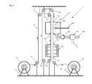
- Fig. 1 shows a sectional view of a coating device 1 according to the invention, by means of which an electrical line 10 can be coated with polymer particles 9.
- the electric wire 10 is unrolled by a unwinding unit 12, which is rotatably supported by a stand 11. Via deflection rollers 13, 14, 15, 18, the electrical line 10 is led to a coating unit 16 and vertically therethrough.
- the electrical line 10 enters through an inlet opening 161 into the coating unit 16, which is shown open, and out of this through an outlet opening 169.
- the inlet opening 161 and the outlet opening 169 are designed such that as little powder as possible can escape from the coating unit 16 without the electrical line 10 touching the edge of the outlet opening 169, for example because of vibrations or oscillations, so that abrasion does not yet occur solidified line coating can be avoided.
- the coating unit 16 contains at least one powder spray head 162 which produces a powder cloud 163 in the coating unit 16 and which is supplied with powder particles 9 via a powder line 164.
- the coating unit 16 also comprises components for the recovery of excess powder 9.
- a pump 167 is connected to the main chamber of the coating unit 16 via a recovery suction funnel 168. By the pump 167, an air flow or gas flow can be generated in the coating unit 16, so that the excess powder particles 9 are directed in the direction of the recovery suction funnel 168.
- a powder separation 165 is connected, which allows the deposition of the sucked powder particles 9 eleven.
- the powder separation 165 comprises at least exits for the exhaust air 8 and for a powder recovery line 166.
- the electrical line 10 enters through the inlet opening 171 vertically into a heating device 17, in which a heating zone is provided. Due to the advantageous arrangement of the heating device 17 immediately below the coating device 16, a deflection and thus a contact of the not yet solidified coating of the electrical line 10 is avoided, which held between the pulleys 15 and 18 vertically and in this orientation by the coating unit 16 and the heater 17 is led.
- the heating device 17 comprises a heating element 172 which can use any heating principle known from the prior art.
- the electrical line 10 After passing through the heating zone, the electrical line 10 exits the heating device 17 through an outlet opening 173. About the guide roller 18, the coated electrical line 10 is supplied to a take-up unit 19, is rotatably supported by a stator 20.
- Fig. 2a shows a cross section of the electric wire 10 of Fig. 1 after passing through the coating unit 1. On the electric line 10 not solidified powder particles 9 are attached. The dashed line shows the circumference of the resulting after solidification cable sheath 91st
- Fig. 2b shows a cross section of the electric wire 10 of Fig. 1 after passing through the heating device 17 with the solidified cable sheath 91, which is symmetrical and over the entire circumference has the same radial wall thickness MD.
- Fig. 2c shows a cross section of a not manufactured according to the inventive method line 10, after the powder coating has an asymmetric cable sheath 92.
- the not yet solidified polymer layer was pulled by the gravitational force on one side down.
- the wall thickness of the cable sheath varies between the smallest wall thickness D1 on the top of the electrical line 10 and the largest wall thickness thickness D2 on the underside of the electrical line 10.
- the material which is displaced by the gravitational force is to be compensated.
- additional material is required, which in addition leads to an increase in the weight of the manufactured conduit 10.
- conduit within the coating zone must be routed over an additional distance within which the additional required material is applied. Cables according to the invention therefore have a lower weight and a lower volume with equivalent quality and can be manufactured at lower costs. At the same time, the production takes place more efficiently and with reduced dimensions of the coating device 1.
- Fig. 3 shows the coating device 1 of Fig. 1 in a preferred embodiment with additional optional functional units.
- the electrical line 10 After unwinding from the unwinding unit 12, the electrical line 10 passes through a pre-treatment unit 21, which can be passed through horizontally or vertically. With regard to the compact construction of the entire coating apparatus 1, however, the optional functional units are also vertically aligned.
- the electrical line 10 is prepared for the efficient and high-quality coating with polymer particles 9.
- a mechanical and / or chemical cleaning of the electrical line 10 and / or the spraying with a chemical substance is provided which increases the adhesion of the polymer particles 9 to the cleaned electrical line 10.
- the electrical conduit 10 Before the electrical conduit 10 reaches the coating zone 16, it is preferably heated in a preheating zone 22, which may be passed horizontally or vertically.
- a preheating zone 22 By heating the electric wire 10, within the coating unit 16, the polymer particles 9 are caused to be partially heated or melted on being attached to the electric wire 10, thereby improving the adhesion.
- the electrical line 10 enters through an inlet opening 221 in the preheating zone 22 and through an outlet opening 223 back out of this.
- the preheating zone 22 includes a heating element 222 which may be based on any heating technique.
- the heating of the electric wire 10 can be achieved by induction, by heat radiation or convection, for which corresponding heating elements 222, e.g. electrical resistances are used.
- the coating unit 16 additionally comprises a powder reservoir 26, which is connected to the powder recovery line 166.
- the powder reservoir 26 can also be supplied with powder automatically by other sources.
- the powder reservoir 26 is connected via a delivery line 261 to a fluidization unit 27.
- Polymer particles 9 pass through the delivery line 261 to the fluidization unit 27, in which the polymer particles 9 are processed with air, a liquid, or a carrier gas to form a mixture which can be sprayed with a conventional powder spray head 162.
- the mixture is transported via a powder line 164 from the fluidization unit 27 to the powder spray head 162.
- a heating element 176 is provided within the coating unit 16, by means of which the reheated mixture and the polymer particles 9 can be heated so that For example, liquid portions of the mixture evaporates and the polymer particles 9 are heated. In this way, the optimum spraying and adhesion of the polymer particles 9 succeeds. In particular, a homogeneous powder cloud 163 is achieved.
- a suction and filter device 23 is also provided, which comprises a passage opening 231 for the electrical line 10, at least one suction hopper 232 and at least one pump 233.
- Task of the suction and filter device 23 is the suction and filtration of emerging from the coating unit 16 polymer particles 9, whereby an entry of polymer particles 9 is prevented in the heater 17.
- the electrical line 10 passes through the heater 17 and passes through the deflection roller 18 to a cooling unit 24, which can be traversed horizontally or vertically.
- the cooling unit 24 may also be connected directly to the heating device 17 and aligned vertically in front of the deflection roller 18.
- the cooling can optionally be carried out by cooling principles known from the prior art.
- the electrical line 10 is sprayed with one or more water jets and / or blown with air and / or a gas.
- the coated electric wire 10 passes through a cross-linking unit 25, in which the polymer material of the finished cable sheath 91 is cross-linked.
- the crosslinking is preferably carried out by irradiation with electrons and / or X-rays or by other methods known from the prior art.
- the line 10 is finally rolled up on the take-up unit 19.
- Fig. 4a shows the preferably configured coating unit 16 of the coating device 1 of Fig. 1 in a sectional view.
- the coating unit 16 has the shape of a pipe or a shaft 160.
- the electrical line 10 enters the coating unit 16 through an inlet opening 161 and out again through an outlet opening 169.
- the section through the coating unit 16 passes exactly through the inlet opening 161 and through the outlet opening 169.
- the coating tube 160 passes in the lower part at an angle of approximately 90 ° directly into the recovery suction 168 and tapers.
- a controllable air flow is generated in the interior of the coating tube 160, which drives the polymer particles 9 emitted by at least one powder spray head 162 through the coating tube 160 at the same speed as the electrical conduit 10 through the coating tube 160 to be led.
- the powder spray head 162 is supplied with polymer particles 9 or the described mixture with polymer particles 9 through the powder line 164.
- a first electrical potential P1 is applied to the electrical line 10 via the deflection roller 15.
- a second electrical potential P2 is applied, which is transferred to the polymer particles 9.
- a third electric potential P3 is applied, which drives the polymer particles 9 radially inward.
- the powder spray head 162 and / or the powder line 164 are electrically insulated from the coating tube 160.
- the potentials P1, P2 and P3 are selected such that the polymer particles 9 are maximally accelerated against the electrical line 10 and concentrate in the region of the center axis of the coating tube 160, whereby an optimal effect can be achieved with minimal use of polymer practical. Due to the high efficiency results in a low material requirement. At the same time, the unwanted deposition of polymer material on device objects is largely avoided.
- Fig. 4b shows a section through the coating unit 16 along the in Fig. 4a drawn section line A - A.
- the powder spray head 162 is arranged eccentrically on the coating tube 160, whereby a directed movement of the powder cloud 163 is achieved in the interior of the coating tube 160, which illustrates the dotted arrow.
- the polymer particles 9 are thus guided helically around the electrical line and coupled even more closely to the electrical line 10.
- the tubular design of the coating unit 16 also allows a compact design.
- Fig. 5 shows the coating device 1 of Fig. 1 in a further preferred embodiment with a plurality of deflection devices 14, 15 1 , 15 2 , 15 3 , 15 4 , 15 5 , 18, by means of which the electrical line 10 is repeatedly guided vertically through the same coating unit 16 therethrough.
- the electrical line 10 is again passed through these two units 16, 17 after a first vertical pass through the coating unit 16 and the heater 17.
- the electrical line 10 as desired by further deflection rollers through the Coating zone 16 and the heater 17 are performed.
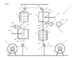
- Fig. 6 shows a further preferred embodiment of the coating device 1 of Fig. 1 which has been equipped with an additional coating unit 16 'and an additional heating device 17'.
- the second coating unit 16 ' is constructed analogously to the first coating unit 16.
- the second heating device 17 ' is constructed analogously to the first heating device 17.
- the number of sequentially arranged coating units is not limited according to the invention.
- Fig. 6 shows that the coating unit 16 or 16 'both spatially below and above the subsequent heating device 17 or 17' can be arranged.
- the vertical pass remains the same.
- FIG. 1 . Fig. 3 . Fig. 5 and Fig. 6 shown embodiments of the inventive coating device 1 can optionally be combined.
- the optional functional units can optionally be added.
Abstract
Die Erfindung betrifft ein Verfahren und eine Vorrichtung zum Beschichten einer elektrischen Leitung (10), die eine oder mehrere Leitungsadern aufweist, mit einer isolierenden Polymer-basierten Schicht in einer Beschichtungsvorrichtung (1), wobei die elektrische Leitung (10) von einer Abwickeleinheit (12) abgerollt wird, durch wenigstens eine Beschichtungseinheit (16) hindurch geführt und mit Polymerpartikeln (9) beaufschlagt wird, durch wenigstens eine Heizzone einer Heizvorrichtung (17) geführt wird, und auf eine Aufwickeleinheit (19) aufgerollt wird. Erfindungsgemäss durchläuft die elektrische Leitung (10) die Beschichtungszone (16) in vertikaler Richtung.The invention relates to a method and a device for coating an electrical line (10) having one or more conductor wires with an insulating polymer-based layer in a coating device (1), wherein the electrical line (10) from an unwinding unit (12 ), is passed through at least one coating unit (16) and charged with polymer particles (9), passed through at least one heating zone of a heating device (17), and rolled up on a winding unit (19). According to the invention, the electrical line (10) passes through the coating zone (16) in the vertical direction.
Description
Die Erfindung betrifft ein Verfahren und Vorrichtung zur Beschichtung von elektrischen Leitungen.The invention relates to a method and apparatus for coating electrical lines.
Elektrische Leitungen, wie Anschluss-, Steuer- oder Datenleitungen (in der Folge als 'Kabel' bezeichnet) werden z.B. für die Verwendung in Maschinen und elektrischen Geräten mit einer isolierenden Schicht versehen, um Kurzschlüsse und Kriechströme zu vermeiden. Die Anforderungen an die isolierende Schicht variieren hierbei je nach Verwendungszweck und Verwendungsumgebung. Parameter, welche die Wahl des Isolationsmaterials beeinflussen, sind beispielsweise der Spannungs- und Strombereich für den das Kabel ausgelegt ist sowie allfällige Temperatur- und Witterungseinflüsse.Electrical lines, such as connection, control or data lines (hereinafter referred to as 'cables') are used e.g. provided with an insulating layer for use in machinery and electrical equipment to prevent short circuits and leakage currents. The requirements for the insulating layer vary depending on the purpose and environment of use. Parameters which influence the choice of the insulating material are, for example, the voltage and current range for which the cable is designed, as well as any temperature and weather influences.
Aufgrund der Anforderungen haben sich Polymer-basierte Isolationsmaterialien, welche durch Extrusion auf die elektrische Leitung aufgebracht werden, in der Praxis durchgesetzt. Ein solches Extrusionsverfahren ist aus der
Die Durchschlagsfestigkeit von Polymer-basierten Materialien der Kabelisolation liegt typischerweise bei 20 kV/mm bis 100 kV/mm. Daraus folgt, dass für Kabel, die für Spannungen von weniger als 1kV ausgelegt sind, selbst eine Isolation von deutlich unter 0.1mm ausreichend wäre, ohne dass elektrische Durchschläge auftreten würden. Durch eine Reduktion der Schichtdicke des Kabelmantels könnten Material und Kosten eingespart und höhere Packungsdichten von mehradrigen Kabeln erreicht werden.The dielectric strength of polymer-based materials of the cable insulation is typically 20 kV / mm to 100 kV / mm. It follows that for cables rated for voltages less than 1kV, even isolation of well below 0.1mm would be sufficient without electrical breakdowns would occur. By reducing the layer thickness of the cable sheath material and costs could be saved and higher packing densities of multi-core cables can be achieved.
Aus der
Ein Nachteil bei diesem Verfahren ist das Erfordernis eines hohen elektrischen Potentials, welches auf den Leiter aufgebracht werden muss. Dieses Potential ist nicht räumlich begrenzt sondern erstreckt sich entlang dem Leiter über die gesamte Beschichtungsvorrichtung und stellt somit ein potentielles Sicherheitsrisiko dar.A disadvantage with this method is the requirement of a high electrical potential which has to be applied to the conductor. This potential is not limited in space but extends along the conductor over the entire coating device and thus represents a potential safety risk.
Ein weiterer Nachteil liegt darin, dass das thermoplastische Pulver nach dem Aufschmelzen nicht gleichmässig um den elektrischen Leiter verteilt ist, sondern eine dickere Schicht auf der Unterseite des Leiters bildet.Another disadvantage is that the thermoplastic powder is not evenly distributed around the electrical conductor after melting, but forms a thicker layer on the underside of the conductor.
Besonders nachteilig ist ferner, dass sich die Vorrichtung innerhalb eines Raumes über eine grosse Distanz erstreckt. Dabei ist nicht nur die Raumnutzung, sondern auch die Nutzung der Medien und der Energie ineffizient, da die Medien und die Energie räumlich verteilt werden.A particular disadvantage is that the device extends within a space over a large distance. Not only is the use of space, but also the use of media and energy inefficient, as the media and energy are spatially distributed.
Die Pulverbeschichtungszone einer Beschichtungsvorrichtung muss generell aufgrund der vorgegebenen Durchlaufgeschwindigkeit und hierbei zu erreichender Schichtdicke dimensioniert werden. Um eine vorgegebene Schichtdicke zu erreichen, ist bei einer hohen Durchlaufgeschwindigkeit der Leitung eine längere Pulverbeschichtungszone erforderlich als bei einer tiefen Durchlaufgeschwindigkeit. Da mit einer hohen Durchlaufgeschwindigkeit der Fertigungsprozess effizienter und kostengünstiger ausgeführt werden kann, wird - unter gleichzeitiger Optimierung der übrigen Parameter - üblicherweise eine möglichst hohe Durchlaufgeschwindigkeit angestrebt. Allerdings ist die Länge der Pulverbeschichtungszone und somit auch die erreichbare Durchlaufgeschwindigkeit oft durch die räumlichen Verhältnisse am Produktionsstandort beschränkt.The powder coating zone of a coating device generally has to be reached due to the predetermined throughput speed and thereby Layer thickness are dimensioned. In order to achieve a given layer thickness, a longer powder coating zone is required at a high line flow rate than at a low throughput speed. Since the production process can be carried out more efficiently and cost-effectively with a high throughput speed, the aim is usually to achieve the highest possible throughput speed while optimizing the other parameters at the same time. However, the length of the powder coating zone and thus the achievable throughput speed is often limited by the spatial conditions at the production site.
Der vorliegenden Erfindung liegt daher die Aufgabe zugrunde, ein verbessertes Verfahren und eine verbesserte Vorrichtung für die Beschichtung einer elektrischen Leitung zu schaffen.The present invention is therefore based on the object to provide an improved method and an improved apparatus for the coating of an electrical line.
Insbesondere ist ein Verfahren anzugeben, mittels dessen polymerbasierte Materialien in beliebig dünnen Schichten auf eine elektrische Leitung aufgebracht werden können.In particular, a method should be provided by means of which polymer-based materials can be applied in any thin layers on an electrical line.
Das erfindungsgemässe Verfahren soll es zudem erlauben, elektrische Leitungen unabhängig vom Leitungsquerschnitt gleichmässig zu beschichten, so dass die Leitung mit einer Isolationsschicht versehen wird, die über den gesamten Leitungsumfang eine einheitliche Wanddicke aufweist.The inventive method should also allow evenly coat electrical lines regardless of the cable cross-section, so that the line is provided with an insulating layer having a uniform wall thickness over the entire circumference of the line.
Die erfindungsgemässe Beschichtungsvorrichtung soll die Anwendung des Verfahrens auch bei beschränkten Raumverhältnissen am Produktionsstandort ermöglichen und die erforderlichen Medien und die Energie mit maximaler Effizienz einsetzen. Insbesondere sollen mit dem erfindungsgemässen Verfahren auch möglichst hohe Durchlaufgeschwindigkeiten erreicht werden.The coating device according to the invention is intended to enable the application of the method even in the case of limited spatial conditions at the production site and to use the required media and energy with maximum efficiency. In particular, as high as possible throughput speeds should be achieved with the method according to the invention.
Diese Aufgabe wird mit einem Verfahren und einer Beschichtungsvorrichtung gelöst, welche die in Anspruch 1 bzw. 15 angegebenen Merkmale aufweist. Vorteilhafte Ausgestaltungen der Erfindung sind in weiteren Ansprüchen angegeben.This object is achieved with a method and a coating device which has the features specified in
Das Verfahren und die Beschichtungsvorrichtung dienen der Beschichtung einer elektrischen Leitung, die eine oder mehrere Leitungsadern aufweist, mit einer isolierenden Polymer-basierten Schicht, wobei die elektrische Leitung
- a) von einer Abwickeleinheit abgerollt wird,
- b) durch wenigstens eine Beschichtungseinheit hindurch geführt und mit Polymerpartikeln beaufschlagt wird,
- c) durch wenigstens eine Heizzone einer Heizvorrichtung hindurch geführt wird, und
- d) auf eine Aufwickeleinheit aufgerollt wird.
- a) is unrolled by an unwinding,
- b) is passed through at least one coating unit and charged with polymer particles,
- c) is passed through at least one heating zone of a heater, and
- d) is rolled up on a take-up unit.
Erfindungsgemäss wird das Verfahren so durchgeführt, dass die elektrische Leitung die Pulverbeschichtungszone in vertikaler Richtung durchläuft. Analog ist die erfindungsgemässe Beschichtungsvorrichtung derart ausgebildet, dass die elektrische Leitung in vertikaler Richtung durch die Pulverbeschichtungszone hindurch geführt wird.According to the invention, the method is carried out so that the electrical line passes through the powder coating zone in the vertical direction. Analogously, the coating device according to the invention is designed such that the electrical line is guided in a vertical direction through the powder coating zone.
Durch die Durchführung der Leitung in vertikaler Richtung durch die Pulverbeschichtungszone, die sich ebenfalls in vertikaler Richtung erstreckt, werden verschiedene Vorteile erzielt.By performing the conduction in the vertical direction through the powder coating zone, which also extends in the vertical direction, various advantages are achieved.
Die elektrische Leitung wird stets entlang einer vertikalen Achse präzise geführt und ist somit von den vorzugsweise gleichmässig verteilten Pulversprühdüsen stets gleich beabstandet. Bereits aus diesem Grund wird ein gleichmässigerer Auftrag der Pufferschicht erzielt. Wesentlich ist ferner, dass sich das Pulver aufgrund der Schwerkraft ebenfalls vertikal und somit parallel und aufgrund der kinetischen Energie bei der Abgabe aus der Sprühdüse mit einer radialen Geschwindigkeitskomponente von allen Seiten gleichmässig zur elektrischen Leitung bewegt. Schichten können daher gleichmässig präzise aufgetragen werden, so dass über den gesamten Leitungsumfang identische Eigenschaften der Isolationsschichten erzielt werden.The electric line is always precisely guided along a vertical axis and is thus always equidistant from the preferably evenly distributed powder spray nozzles. For this reason alone, a more even application of the buffer layer is achieved. Essential Further, due to gravity, the powder also moves vertically, and thus in parallel and due to the kinetic energy in dispensing from the spray nozzle with a radial velocity component, uniformly from all sides to the electrical conduit. Layers can therefore be applied uniformly precisely, so that identical properties of the insulation layers are achieved over the entire circumference of the cable.
Da die Beschichtung mit hoher Präzision erfolgt, ist es zudem möglich den Materialauftrag insgesamt zu reduzieren, weshalb gegebenenfalls teures Material eingespart werden kann.Since the coating is done with high precision, it is also possible to reduce the total material order, which is why expensive material can be saved if necessary.
Bei Anwendung des erfindungsgemässen Verfahrens kann am Produktionsstandort zudem die für die Beschichtungsvorrichtung benötigte Grundfläche wesentliche reduziert werden. Insgesamt reduziert sich der Raumbedarf, so dass mehr Raum für andere Fertigungsprozesse zur Verfügung steht. Durch die vertikale Ausrichtung der Pulverbeschichtungszone kann zudem die am Produktionsstandort vorhandene Raumhöhe optimal genutzt werden.When using the method according to the invention, the base area required for the coating device can also be substantially reduced at the production site. Overall, the space requirement is reduced, so that more space is available for other production processes. Due to the vertical orientation of the powder coating zone, the room height available at the production site can also be optimally utilized.
Die vertikale Ausrichtung der Pulverbeschichtungszone führt zu einem kompakteren Aufbau der Beschichtungsvorrichtung, wodurch beispielsweise kostengünstigere Isolationsvorrichtungen realisiert werden können. Ferner können Leitungen für die Medienversorgung kürzer ausgelegt werden. Insgesamt ist mit Energieeinsparungen zu rechnen.The vertical orientation of the powder coating zone leads to a more compact construction of the coating device, whereby, for example, less expensive insulation devices can be realized. Furthermore, lines for the media supply can be made shorter. Overall, energy savings can be expected.
Besonders vorteilhaft ist zudem, dass auf geringerer Grundfläche längere Beschichtungszonen realisiert werden können, so dass die maximale Durchlaufgeschwindigkeit der elektrischen Leitung durch die Beschichtungsvorrichtung wesentlich erhöht werden kann.It is also particularly advantageous that longer coating zones can be realized on a smaller base area, so that the maximum passage speed of the electrical line through the coating device can be substantially increased.
Besonders vorteilhaft ist ferner, dass mehrlagige Isolationsschichten anhand des erfindungsgemässen Verfahrens und der erfindungsgemässen Beschichtungsvorrichtung besonders vorteilhaft realisiert werden können, indem die elektrische Leitung mehrfach vertikal durch eine einzige Beschichtungszone oder sequenziellen vertikal durch mehrere parallel zueinander ausgerichtete Beschichtungseinheiten geführt wird. Dabei wird vorzugsweise vorgesehen, dass nach jedem Durchlauf durch eine Beschichtungszone eine Heizzone durchlaufen und die bereits aufgetragene Schicht stabilisiert wird.It is also particularly advantageous that multilayer insulating layers can be realized particularly advantageously by means of the method according to the invention and the coating device according to the invention by passing the electrical line through a single coating zone or sequentially vertically through a plurality of coating units oriented parallel to one another. It is preferably provided that pass through a heating zone after each pass through a coating zone and the already applied layer is stabilized.
Durch die vertikale Ausrichtung der Beschichtungseinheit bzw. der Beschichtungseinheiten kann somit eine Beschichtungsvorrichtung für die Realisierung mehrlagiger Isolationsschichten mit geringem Platzbedarf im Vergleich zu einer Vorrichtung mit horizontaler Ausrichtung der Beschichtungseinheiten erreicht werden.As a result of the vertical alignment of the coating unit or of the coating units, it is thus possible to achieve a coating device for the realization of multilayer insulation layers with a small space requirement in comparison to a device with a horizontal orientation of the coating units.
Die zumindest eine Beschichtungseinheit kann eine oder mehrere Pulversprühdüsen umfassen, über die Polymerpartikel abgeben werden. In vorzugsweisen Ausgestaltungen ist die Beschichtungsvorrichtung mit mehreren Pulversprühdüsen versehen, die entweder in einer Ebene oder vorzugsweise in mehreren übereinander liegenden Ebenen ringförmig um die Förderachse der elektrischen Leitung angeordnet sein. Vorteilhaft ist ferner eine ringförmige Pulversprühdüse verwendbar, welche die elektrische Leitung zumindest teilweise umschliesst.The at least one coating unit may comprise one or more powder spray nozzles via which polymer particles are released. In preferred embodiments, the coating device is provided with a plurality of powder spray nozzles, which are arranged either in a plane or preferably in several superimposed planes annularly around the conveying axis of the electrical line. Advantageously, an annular Pulversprühdüse is also used, which at least partially surrounds the electrical line.
Vorzugsweise ist die zumindest eine Beschichtungseinheit als Schacht oder Rohr ausgeführt, durch den bzw. das die elektrische Leitung in vertikaler Richtung hindurchgeführt wird. Der Schacht weist vorzugsweise eine zylindrische Form auf. Der Auftrag der Polymerpartikel auf die elektrische Leitung erfolgt innerhalb dieses Schachtes, dessen Durchmesser vorzugsweise zwischen 1cm und 50cm liegt. Aufgrund der vertikalen Führung und das Vermeiden des Durchhängens der elektrischen Leitung kann ein sehr geringer Schachtdurchmesser gewählt werden, der eine effiziente Pulverbeschichtung gewährleistet und Materialverluste entsprechend vermeidet.Preferably, the at least one coating unit is designed as a shaft or pipe, through which or the electrical line is passed in the vertical direction. The shaft preferably has a cylindrical shape. The order of the polymer particles on the electrical line takes place within this shaft, whose diameter preferably between 1cm and 50cm. Due to the vertical guidance and the avoidance of the sagging of the electrical line, a very small shaft diameter can be selected, which ensures an efficient powder coating and avoids material losses accordingly.
In einer weiteren vorzugsweisen Ausgestaltung wird innerhalb der zumindest einen Beschichtungseinheit mittels wenigstens einer Pumpe ein gleichmässiger und kontinuierlicher Luftstrom erzeugt. Vorzugsweise wird der Luftstrom derart gesteuert, dass dessen Geschwindigkeit bzw. die Geschwindigkeit der im Luftstrom geförderten Polymerpartikel etwa der Geschwindigkeit entspricht, mit die elektrische Leitung durch die Beschichtungseinheit geführt wird. In einer bevorzugten Ausführungsform ist das Verhältnis der Durchlaufgeschwindigkeit der elektrischen Leitung zur Geschwindigkeit des Luftstroms im Bereich von 1:10 bis 10:1.In a further preferred embodiment, a uniform and continuous air flow is generated within the at least one coating unit by means of at least one pump. Preferably, the air flow is controlled such that its speed or the speed of the polymer particles conveyed in the air flow corresponds approximately to the speed with which the electrical line is passed through the coating unit. In a preferred embodiment, the ratio of the electrical line transit speed to the air flow velocity is in the range of 1:10 to 10: 1.
In einer weiteren bevorzugten Ausführungsform ist zwischen der Beschichtungseinheit und der Heizzone eine Absaugeinheit vorgesehen, welche die Ausbreitung der Pulverwolke ausserhalb der Beschichtungseinheit verhindert oder zumindest stark reduziert und eine zu hohe Konzentration der Pulver-/Polymerpartikeln in der Heizzone vermeidet, welche zu einer Pulverexplosion führen könnte. Zudem wird die Anlagerung von Pulverpartikeln auf Komponenten der Vorrichtung ausserhalb der Beschichtungseinheit reduziert, was den Wartungsaufwand vermindert. Die Absaugeinheit, die einen Luftstrom ausstossen oder anziehen kann, kann beispielsweise einen Querstrom oder Gegenstrom mit Luft oder Inertgas, abgeben, durch den die Polymerpartikel abgelenkt oder abgesaugt werden.In a further preferred embodiment, a suction unit is provided between the coating unit and the heating zone, which prevents or at least greatly reduces the spread of the powder cloud outside the coating unit and avoids too high a concentration of the powder / polymer particles in the heating zone, which could lead to a powder explosion , In addition, the addition of powder particles is reduced to components of the device outside the coating unit, which reduces the maintenance costs. The suction unit, which can eject or attract an air stream, can, for example, emit a crossflow or countercurrent with air or inert gas, through which the polymer particles are deflected or sucked off.
Vorzugsweise ist zudem eine Absaug- und Filtervorrichtung vorgesehen, mittels der das Pulver abgesaugt, gefiltert und rezykliert werden kann.Preferably, a suction and filter device is also provided, by means of which the powder can be sucked off, filtered and recycled.
Vorzugsweise wird die elektrische Leitung nach dem Durchlaufen der Beschichtungszone vertikal durch wenigstens eine Heizzone einer Heizvorrichtung geführt, in der die Haftung der auf der elektrischen Leitung angelagerten Polymerpartikel verbessert und die Beschichtung unter Ausschluss von Öffnungen homogen ausgebildet wird. Die Temperatur der Heizzone sowie die Durchlaufzeit sind vorzugsweise entsprechend dem verwendeten Polymermaterial steuerbar.Preferably, after passing through the coating zone, the electrical line is passed vertically through at least one heating zone of a heating device in which the adhesion of the polymer particles deposited on the electrical line is improved and the coating is made homogeneous, excluding openings. The temperature of the heating zone and the cycle time are preferably controllable according to the polymer material used.
In vorzugsweisen Ausgestaltungen wird die elektrische Leitung mehrfach durch die gleiche Heizzone oder durch mehrere hintereinanderliegende Heizzonen durchgeführt. Nach dem vertikalen Durchlauf durch die erste Heizzone ist die unverändert gleichmässige Beschichtung stabilisiert, so dass sie über Umlenkrolle geführt werden kann. Besonders vorteilhaft kann die elektrische Leitung induktiv, durch Strahlung oder durch Konvektion erwärmt werden.In preferred embodiments, the electrical line is repeatedly performed by the same heating zone or by several consecutive heating zones. After the vertical passage through the first heating zone, the unchanged uniform coating is stabilized so that it can be guided over deflection roller. Particularly advantageously, the electrical line can be heated inductively, by radiation or by convection.
In einer weiteren bevorzugten Ausführungsform wird die Anlagerung der Polymerpartikel an der elektrischen Leitung durch eine elektrostatische Potentialdifferenz zwischen diesen beiden Komponenten verbessert. Vorzugsweise werden die Polymerpartikel beim Durchgang durch die zumindest eine Pulversprühdüse mit einem elektrostatischen Potential beaufschlagt und dadurch elektrostatisch geladen. Vorzugsweise wird auch die elektrische Leitung mit einem elektrostatischen Potential beaufschlagt. Wesentlich ist die Potenzialdifferenz zwischen den Polymerpartikeln und der elektrischen Leitung, weshalb die Polymerpartikel oder die elektrische Leitung auch Erdpotential aufweisen kann.In a further preferred embodiment, the attachment of the polymer particles to the electrical line is improved by an electrostatic potential difference between these two components. When passing through the at least one powder spray nozzle, the polymer particles are preferably exposed to an electrostatic potential and thereby charged electrostatically. Preferably, the electrical line is subjected to an electrostatic potential. What is essential is the potential difference between the polymer particles and the electrical line, which is why the polymer particles or the electrical line can also have ground potential.
Durch die Potentialdifferenz zwischen den Polymerpartikeln und der elektrischen Leitung werden die Polymerpartikel in Richtung zur elektrischen Leitung beschleunigt.The potential difference between the polymer particles and the electrical conduction accelerates the polymer particles in the direction of the electrical conduction.
In einer bevorzugten Ausführungsform wird der Schacht innerhalb der Beschichtungsvorrichtung mit einem weiteren, vom Potential der elektrischen Leitung unabhängig einstellbaren, elektrostatischen Potential beaufschlagt, so dass der Schacht als zusätzliche Elektrode dient, welche die ionisierten Polymerpartikel in Richtung der elektrischen Leitung beschleunigt. Die Polymerpartikel werden daher entlang der Transportphase der elektrischen Leitung konzentriert, so dass die Beschichtung mit hoher Effizienz erfolgt.In a preferred embodiment, the shaft is subjected to a further electrostatic potential that can be set independently of the potential of the electrical line within the coating device, so that the shaft serves as an additional electrode which accelerates the ionized polymer particles in the direction of the electrical line. The polymer particles are therefore concentrated along the transport phase of the electrical conduction, so that the coating is carried out with high efficiency.
Besonders vorteilhaft kann das elektrostatische Potential über Umlenkrollen auf die elektrische Leitung übertragen. Vorzugsweise sind die Umlenkrollen, die aus Metall, Kunststoff oder einer Kombination dieser Materialien gefertigt sind, über Schleifkontakte mit der Potentialquelle verbunden.Particularly advantageously, the electrostatic potential can be transmitted via deflection rollers to the electrical line. Preferably, the deflection rollers, which are made of metal, plastic or a combination of these materials, connected via sliding contacts with the potential source.
In einer weiteren erfindungsgemässen Ausführungsform wird die elektrische Leitung vorzugsweise vertikal durch eine der Beschichtungseinheit vorgeschaltete Vorbearbeitungsstufe durchgeführt. Beim Durchlaufen der Vorbearbeitungsstufe kann die elektrische Leitung mechanisch und/oder chemisch gereinigt werden. Ebenso kann die elektrische Leitung mit einem flüssigen, dampfförmigen oder pulverförmigen Material beschichtet werden, das die Ankopplung der Polymerpartikel an die elektrische Leitung in der Beschichtungseinheit fördert und verbessert. Die genannten Vorprozesse können sequenziell oder in Kombination in einer oder mehreren Vorbearbeitungsstufen durchgeführt werden.In a further embodiment according to the invention, the electrical line is preferably carried out vertically through a pre-processing stage upstream of the coating unit. When passing through the pre-processing stage, the electrical line can be mechanically and / or chemically cleaned. Likewise, the electrical line can be coated with a liquid, vaporous or powdery material, which promotes and improves the coupling of the polymer particles to the electrical line in the coating unit. The aforementioned preliminary processes can be carried out sequentially or in combination in one or more preprocessing stages.
Vorzugsweise umfasst die Beschichtungsvorrichtung eine der Heizvorrichtung nachgeschaltete Kühleinheit, mittels der die auf die elektrische Leitung aufgetragene Beschichtung gekühlt werden kann. Durch das unverzügliche Kühlen der elektrischen Leitung nach Verlassen der Heizzone wird der aufgetragenen Beschichtung Wärmeenergie entzogen und abgeführt, bevor die Wärmeenergie in das innere der elektrischen Leitung eindringen und dortige Komponenten verändern kann. Die Kühlung mittels der Kühleinheit kann durch Abgabe eines gegen die elektrische Leitung gerichteten Strahls eines Gases oder Gasgemisches Luftstrahls oder einer Flüssigkeit erfolgen. Ferner kann die elektrische Leitung durch ein Flüssigkeitsbad oder Dampf geführt werden. Als Materialien sind Luft, Wasser, ein Inertgas, flüssiger Stickstoff sowie Kombinationen davon vorteilhaft einsetzbar.Preferably, the coating device comprises a cooling unit connected downstream of the heating device, by means of which the coating applied to the electrical line can be cooled. Due to the immediate cooling of the electrical line after leaving the heating zone of the applied coating heat energy is removed and removed before the Heat energy can penetrate into the interior of the electrical line and change local components. The cooling by means of the cooling unit can be effected by delivery of a directed against the electrical line jet of a gas or gas mixture air jet or a liquid. Further, the electrical conduction may be passed through a liquid bath or steam. As materials, air, water, an inert gas, liquid nitrogen and combinations thereof are advantageously used.
In einer weiteren bevorzugten Ausführungsform wird die elektrische Leitung nach der Beschichtung durch eine oder mehrere Nachbearbeitungsstufen, insbesondere durch eine Vernetzungseinheit durchgeführt, mittels der die Polymerbasierte Beschichtung vernetzt wird. Dies kann durch Röntgenstrahlung, Elektronenstrahlung oder durch chemische Vernetzung geschehen. Ferner kann eine Nachbearbeitungsstufe vorgesehen werden, mittels der wenigstens eine Funktionsschicht auf die beschichtete elektrische Leitung aufgetragen wird. Vorzugsweise eine oder mehrere Funktionsschichten aufgetragen, mittels der die Widerstandsfähigkeit der elektrischen Leitung gegen mechanische, chemische und/oder thermische Einwirkungen, insbesondere Feuer, erhöht wird.In a further preferred embodiment, the electrical line is carried out after the coating by one or more post-processing steps, in particular by a crosslinking unit, by means of which the polymer-based coating is crosslinked. This can be done by X-rays, electron beams or by chemical crosslinking. Furthermore, a post-processing stage can be provided by means of which at least one functional layer is applied to the coated electrical line. Preferably, one or more functional layers applied, by means of which the resistance of the electrical line against mechanical, chemical and / or thermal effects, in particular fire, is increased.
Mittels des erfindungsgemässen Verfahrens können beliebige Arten von pulverförmigen Polymermaterialien auf die elektrische Leitung aufgetragen werden. Besonders effizient ist die Verwendung von Polymerpartikeln mit einer mittleren Partikelgrösse unter 400µm. Der Schmelzflussindex (gemäss ISO 1133) des Polymermaterials ist zudem vorzugsweise grösser als 2 g/10min.By means of the method according to the invention, any types of pulverulent polymer materials can be applied to the electrical line. The use of polymer particles having an average particle size of less than 400 μm is particularly efficient. The melt flow index (according to ISO 1133) of the polymer material is moreover preferably greater than 2 g / 10 min.
Um das Risiko einer Pulverexplosion zu reduzieren wird das Verfahren vorzugsweise in einer Atmosphäre mit Inertgas, wie Helium, Neon, Xenon, Argon oder Stickstoff, durchgeführt. Dazu wird erfindungsgemässe Beschichtungsvorrichtung zumindest teilweise innerhalb einer Kammer angeordnet, der das Inertgas zugeführt wird.In order to reduce the risk of powder explosion, the process is preferably carried out in an atmosphere of inert gas, such as Helium, neon, xenon, argon or nitrogen. For this purpose, the coating device according to the invention is arranged at least partially within a chamber, to which the inert gas is supplied.
Nachfolgend wird die Erfindung anhand von Zeichnungen näher erläutert. Dabei zeigt:
- Fig. 1
- eine Schnittdarstellung einer erfindungsgemässen Beschichtungsvorrichtung 1, mittels der eine elektrische Leitung 10
mit Polymerpartikeln 9 beschichtet wird; - Fig. 2a
- den Querschnitt der elektrischen Leitung 10 von
Fig. 1 , welche inder Beschichtungseinheit 16mit Pulverpartikeln 9 beschichtet wurde; - Fig. 2b
- den Querschnitt der elektrischen Leitung 10 von
Fig. 1 mit ausgehärtetem Kabelmantel 91, der aus derBeschichtung mit Polymerpartikeln 9 resultiert; - Fig. 2c
- den Querschnitt einer nicht nach dem erfindungsgemässen Verfahren gefertigten elektrischen Leitung 10, die einen asymmetrischen Kabelmantel 93 aufweist;
- Fig. 3
- die
Beschichtungsvorrichtung 1 vonFig. 1 ergänzt mit zusätzlichen Komponenten zur Prozessoptimierung; - Fig. 4a
- die
Beschichtungseinheit 16der Beschichtungsvorrichtung 1 vonFig. 1 in einer vorzugsweisen Ausgestaltung; - Fig. 4b
- einen Schnitt durch die
Beschichtungseinheit 16 entlang der inFig. 4a eingezeichneten Schnittlinie A--A; - Fig. 5
- die
Beschichtungsvorrichtung 1 vonFig. 1 in einer weiteren vorzugsweisen Ausgestaltungmit mehreren Umlenkvorrichtungen - Fig. 6
- die
Beschichtungsvorrichtung 1 vonFig. 1 mit zwei Beschichtungseinheiten
- Fig. 1
- a sectional view of a
coating device 1 according to the invention, by means of which anelectrical line 10 is coated withpolymer particles 9; - Fig. 2a
- the cross section of the
electrical line 10 ofFig. 1 which has been coated in thecoating unit 16 withpowder particles 9; - Fig. 2b
- the cross section of the
electrical line 10 ofFig. 1 withhardened cable jacket 91, resulting from the coating withpolymer particles 9; - Fig. 2c
- the cross section of a not manufactured according to the inventive method
electrical line 10 having an asymmetric cable sheath 93; - Fig. 3
- the
coating device 1 ofFig. 1 supplemented with additional components for process optimization; - Fig. 4a
- the
coating unit 16 of thecoating device 1 ofFig. 1 in a preferred embodiment; - Fig. 4b
- a section through the
coating unit 16 along inFig. 4a drawn section line A - A; - Fig. 5
- the
coating device 1 ofFig. 1 in a further preferred embodiment with a plurality ofdeflection devices electrical line 10 is repeatedly guided vertically through thesame coating unit 16 therethrough; and - Fig. 6
- the
coating device 1 ofFig. 1 with twocoating units 16, 16 'and twoheaters 17, 17', which are traversed vertically by theelectrical line 10 sequentially.
Die Beschichtungseinheit 16 enthält zumindest einen Pulversprühkopf 162 der eine Pulverwolke 163 in der Beschichtungseinheit 16 produziert und der über eine Pulverleitung 164 mit Pulverpartikeln 9 versorgt wird.The
Die Beschichtungseinheit 16 umfasst zudem Komponenten zur Rückgewinnung von überschüssigem Pulver 9. Über einen Rückgewinnungsansaugtrichter 168 ist eine Pumpe 167 mit der Hauptkammer der Beschichtungseinheit 16 verbunden. Durch die Pumpe 167 kann in der Beschichtungseinheit 16 ein Luftstrom oder Gasstrom erzeugt werden, so dass die überschüssigen Pulverpartikel 9 in Richtung des Rückgewinnungsansaugtrichters 168 gelenkt werden. An die Pumpe 167 ist eine Pulverabscheidung 165 angeschlossen, die die Abscheidung der angesaugten Pulverpartikel 9 elf ermöglicht. Die Pulverabscheidung 165 umfasst zumindest Ausgänge für die Abluft 8 sowie für eine Pulverrückgewinnungsleitung 166.The
Unmittelbar anschliessend an die Beschichtungseinheit 16 tritt die elektrische Leitung 10 durch die Eintrittsöffnung 171 vertikal in eine Heizvorrichtung 17 ein, in der eine Heizzone vorgesehen ist. Durch die vorteilhafte Anordnung der Heizvorrichtung 17 unmittelbar unterhalb der Beschichtungsvorrichtung 16 wird eine Umlenkung und somit eine Kontaktierung der noch nicht verfestigten Beschichtung der elektrischen Leitung 10 vermieden, die zwischen den Umlenkrollen 15 und 18 vertikal gehalten und in dieser Ausrichtung durch die Beschichtungseinheit 16 und die Heizvorrichtung 17 geführt wird.Immediately following the
Bei der Bemessung der Distanz zwischen der Austrittsöffnung 169 der Beschichtungseinheit 16 und der Eintrittsöffnung 171 der Heizvorrichtung 17 ist zu beachten, dass Polymerpartikel 9 aus der Beschichtungseinheit 16 austreten und sich in der Heizvorrichtung 17 entzünden können, was zu einer Pulverexplosion führen kann. Dieses Risiko wird minimiert, indem die Durchmesser der Austrittsöffnung 169 sowie der Eintrittsöffnung 171 möglichst klein gehalten und vorzugsweise entsprechend dem Durchmesser der elektrischen Leitung 10 gewählt werden. Ferner kann die Austrittsöffnung 169 oder die Eintrittsöffnung 171 mit einem Luftstrahl beaufschlagt werden.When dimensioning the distance between the outlet opening 169 of the
Die Heizvorrichtung 17 umfasst ein Heizelement 172, welches ein beliebiges, aus dem Stand der Technik bekanntes, Heizprinzip verwenden kann.The
Nach dem Durchlaufen der Heizzone tritt die elektrische Leitung 10 durch eine Austrittsöffnung 173 aus der Heizvorrichtung 17 aus. Über die Umlenkrolle 18 wird die beschichtete elektrische Leitung 10 einer Aufwickeleinheit 19 zugeführt, von einem Ständer 20 drehbar gehalten ist.After passing through the heating zone, the
Nach dem Abwickeln von der Abwickeleinheit 12 durchläuft die elektrische Leitung 10 eine Vorbehandlungseinheit 21, die horizontal oder vertikal durchlaufen werden kann. Hinsichtlich des kompakten Aufbaus der gesamten Beschichtungsvorrichtung 1 werden jedoch auch die optionalen Funktionseinheiten vertikal ausgerichtet.After unwinding from the unwinding
In der Vorbehandlungseinheit 21 wird die elektrische Leitung 10 für die effiziente und qualitativ hochwertige Beschichtung mit Polymerpartikeln 9 vorbereitet. Vorzugsweise wird eine mechanische und/oder chemische Reinigung der elektrischen Leitung 10 und/oder das Besprühen mit einer chemischen Substanz vorgesehen, welche die Haftfähigkeit der Polymerpartikel 9 an der gereinigten elektrischen Leitung 10 erhöht.In the
Bevor die elektrische Leitung 10 die Beschichtungszone 16 erreicht, wird sie vorzugsweise in einer Vorheizzone 22 erwärmt, die horizontal oder vertikal durchlaufen werden kann. Durch das Erwärmen der elektrischen Leitung 10 wird innerhalb der Beschichtungseinheit 16 bewirkt, dass die Polymerpartikel 9 beim Anlagern an die elektrische Leitung 10 partiell erwärmt oder geschmolzen werden, wodurch das Anhaften verbessert wird. Die elektrische Leitung 10 tritt durch eine Eintrittsöffnung 221 in die Vorheizzone 22 ein und durch eine Austrittsöffnung 223 wieder aus dieser aus. Die Vorheizzone 22 umfasst ein Heizelement 222, welches auf einer beliebigen Heiztechnik basieren kann. Die Erwärmung der elektrischen Leitung 10 kann durch Induktion, durch Wärmestrahlung oder Konvektion erzielt werden, wofür entsprechende Heizelemente 222, z.B. elektrische Widerstände verwendet werden.Before the
Die Beschichtungseinheit 16 umfasst zusätzlich einen Pulverspeicher 26, welcher mit der Pulverrückgewinnungsleitung 166 verbunden ist. Der Pulverspeicher 26 kann zudem durch weitere Quellen automatisch mit Pulver versorgt werden.The
Der Pulverspeicher 26 ist über eine Förderleitung 261 mit einer Fluidisierungseinheit 27 verbunden. Durch die Förderleitung 261 gelangen Polymerpartikel 9 zur Fluidisierungseinheit 27, in der die Polymerpartikel 9 mit Luft, einer Flüssigkeit, oder einem Trägergas zu einem Gemisch verarbeitet werden, welches mit einem gängigen Pulversprühkopf 162 versprüht werden kann. Das Gemisch wird über eine Pulverleitung 164 von der Fluidisierungseinheit 27 zum Pulversprühkopf 162 transportiert.The
In einer bevorzugten Ausgestaltung wird innerhalb der Beschichtungseinheit 16 ein Heizelement 176 vorgesehen, mittels dessen das eingespielte Gemisch und die Polymerpartikel 9 erwärmt werden können, so dass beispielsweise Flüssigkeitsanteile des Gemisches verdampft und die Polymerpartikel 9 erwärmt werden. Auf diese Weise gelingt das optimale Einsprühen und Anhaften der Polymerpartikel 9. insbesondere wird eine homogene Pulverwolke 163 erzielt.In a preferred embodiment, a
Zwischen der Beschichtungseinheit 16 und der Heizvorrichtung 17 ist zudem eine Absaug- und Filtervorrichtung 23 vorgesehen, die eine Durchlassöffnung 231 für die elektrische Leitung 10, zumindest einen Ansaugtrichter 232 sowie zumindest eine Pumpe 233 umfasst. Aufgabe der Absaug- und Filtervorrichtung 23 ist das Ansaugen und die Filtrierung von aus der Beschichtungseinheit 16 austretenden Polymerpartikeln 9, wodurch ein Eintreten von Polymerpartikeln 9 in die Heizvorrichtung 17 verhindert wird.Between the
Nach der Absaug- und Filtervorrichtung 23 durchläuft die elektrische Leitung 10 die Heizvorrichtung 17 und gelangt über die Umlenkrolle 18 zu einer Kühleinheit 24, die horizontal oder vertikal durchlaufen werden kann. Die Kühleinheit 24 kann auch vor der Umlenkrolle 18 direkt an die Heizvorrichtung 17 angeschlossen und vertikal ausgerichtet sein. Die Kühlung kann wahlweise durch aus dem Stand der Technik bekannte Kühlprinzipien durchgeführt werden. Vorzugsweise wird die elektrische Leitung 10 mit einem oder mehreren Wasserstrahlen bespritzt und/oder mit Luft und/oder einem Gas angeblasen.After the suction and
Nach der Kühleinheit 24 durchläuft die beschichtete elektrische Leitung 10 eine Vernetzungseinheit 25, in der das Polymermaterial des gefertigten Kabelmantels 91 quervernetzt wird. Die Vernetzung erfolgt vorzugsweise durch Bestrahlung mit Elektronen und/oder Röntgenstrahlen oder durch andere aus dem Stand der Technik bekannte Methoden.After the
Die Leitung 10 wird abschliessend auf die Aufwickeleinheit 19 aufgerollt.The
Schematisch ist in
Die Potentiale P1, P2 und P3 sind derart gewählt, dass die Polymerpartikel 9 maximal gegen die elektrische Leitung 10 beschleunigt werden und sich im Bereich der Mittelachse des Beschichtungsrohres 160 konzentrieren, wodurch mit minimalem Einsatz von Polymerpraktikum eine optimale Wirkung erzielen lässt. Aufgrund der hohen Effizienz resultiert ein geringer Materialbedarf. Gleichzeitig wird die unerwünschte Ablagerung von Polymermaterial an Vorrichtungsgegenständen weitgehend vermieden.The potentials P1, P2 and P3 are selected such that the
Die in
- 11
- Vorrichtung zur Beschichtung von elektrischen LeitungenDevice for coating electrical lines
- 1010
- elektrische Leitungelectrical line
- 1111
- Ständer für KabelrolleStand for cable reel
- 1212
- Abwickeleinheitunwinding
- 1313
- Umlenkrolleidler pulley
- 1414
- Umlenkrolleidler pulley
- 1515
- Umlenkrolleidler pulley
- 151 - 155 15 1 - 15 5
- Umlenkrollenguide rollers
- 16, 16'16, 16 '
- Beschichtungseinheitcoating unit
- 160160
- BeschichtungsrohrApplication pipe
- 161, 161'161, 161 '
- Eintrittsöffnunginlet opening
- 162, 162'162, 162 '
- PulversprühkopfPulversprühkopf
- 163, 163'163, 163 '
- Pulverwolkepowder cloud
- 164, 164'164, 164 '
- Pulverleitungpowder conduit
- 165165
- Pulverabscheidungpowder deposition
- 166166
- PulverrückgewinnungsleitungPowder recovery conduit
- 167167
- Pumpepump
- 168168
- RückgewinnungsansaugtrichterRückgewinnungsansaugtrichter
- 169, 169'169, 169 '
- Austrittsöffnungoutlet opening
- 17, 17'17, 17 '
- Heizvorrichtungheater
- 171, 171'171, 171 '
- Eintrittsöffnunginlet opening
- 172, 172'172, 172 '
- Heizelementheating element
- 173, 173'173, 173 '
- Austrittsöffnungoutlet opening
- 1818
- Umlenkrolleidler pulley
- 1919
- Aufwickeleinheitrewinder
- 2020
- Ständer für KabelrolleStand for cable reel
- 2121
- Vorbehandlungseinheitpretreatment unit
- 2222
- Vorheizzonepreheating
- 221221
- Eintrittsöffnunginlet opening
- 222222
- Heizelementheating element
- 223223
- Austrittsöffnungoutlet opening
- 2323
- Absaug- und FiltervorrichtungSuction and filter device
- 231231
- DurchlassöffnungPort
- 232232
- AnsaugtrichterVelocity Stacks
- 233233
- Pumpepump
- 2424
- Kühleinheitcooling unit
- 2525
- Vernetzungseinheitcrosslinking unit
- 2626
- Pulverspeicherpowder storage
- 261261
- Förderleitungdelivery line
- 2727
- Fluidisierungseinheitfluidising
- 88th
- Abluftexhaust
- 99
- Pulverpartikelpowder particles
- 9191
- Kabelmantelcable sheath
- 9292
- Asymmetrischer KabelmantelAsymmetrical cable sheath
- MDMD
- Dicke des KabelmantelsThickness of the cable sheath
- D1D1
- Minimale Dicke des asymmetrischen KabelmantelsMinimum thickness of the asymmetrical cable sheath
- D2D2
- Maximale Dicke des asymmetrischen KabelmantelsMaximum thickness of the asymmetrical cable sheath
Claims (15)
Priority Applications (1)
| Application Number | Priority Date | Filing Date | Title |
|---|---|---|---|
| EP14153573.2A EP2902113B1 (en) | 2014-02-02 | 2014-02-02 | Method and device for coating electric leads |
Applications Claiming Priority (1)
| Application Number | Priority Date | Filing Date | Title |
|---|---|---|---|
| EP14153573.2A EP2902113B1 (en) | 2014-02-02 | 2014-02-02 | Method and device for coating electric leads |
Publications (2)
| Publication Number | Publication Date |
|---|---|
| EP2902113A1 true EP2902113A1 (en) | 2015-08-05 |
| EP2902113B1 EP2902113B1 (en) | 2019-05-22 |
Family
ID=50070334
Family Applications (1)
| Application Number | Title | Priority Date | Filing Date |
|---|---|---|---|
| EP14153573.2A Active EP2902113B1 (en) | 2014-02-02 | 2014-02-02 | Method and device for coating electric leads |
Country Status (1)
| Country | Link |
|---|---|
| EP (1) | EP2902113B1 (en) |
Cited By (5)
| Publication number | Priority date | Publication date | Assignee | Title |
|---|---|---|---|---|
| CN111054564A (en) * | 2019-12-14 | 2020-04-24 | 重庆材料研究院有限公司 | Wire rod surface spraying device |
| CN112191429A (en) * | 2020-10-12 | 2021-01-08 | 衡阳凌云特种材料有限公司 | Insulating paint coating treatment device for high-strength chemical fiber insulating rope production |
| CN114534978A (en) * | 2022-03-01 | 2022-05-27 | 湖北楚天电缆实业有限公司 | Cable core processing equipment and processing method of waterproof optical cable |
| CN114798233A (en) * | 2022-05-05 | 2022-07-29 | 湖北楚天电缆实业有限公司 | Production device and production method of corrosion-resistant optical cable |
| CN116487123A (en) * | 2023-05-18 | 2023-07-25 | 湖南盛世电线电缆有限公司 | Higher cladding device of stability for cable manufacture |
Citations (6)
| Publication number | Priority date | Publication date | Assignee | Title |
|---|---|---|---|---|
| US3589332A (en) * | 1968-07-18 | 1971-06-29 | Bernhard Dinse | Apparatus for insulating thin electric conductors, particularly extremely thin copper conductors, with thermoplastic synthetic materials |
| US3616983A (en) * | 1967-12-27 | 1971-11-02 | Matsushita Electric Works Ltd | Apparatus for continuously forming plastic-coated metallic tubings |
| US4104416A (en) * | 1976-02-05 | 1978-08-01 | Canada Wire And Cable Limited | Thin walled protective coatings by electrostatic powder deposition |
| US5310582A (en) * | 1993-02-19 | 1994-05-10 | Board Of Trustees Operating Michigan State University | Apparatus and high speed method for coating elongated fibers |
| DE102006002192A1 (en) | 2006-01-16 | 2007-07-19 | Trithor Gmbh | Method for electric insulation of super-conducting conductor, involves sputtering insulating material on to conductor surface |
| EP1990808A2 (en) | 2007-05-07 | 2008-11-12 | JJI Technologies, LLC | Flame retardant wire and cable |
-
2014
- 2014-02-02 EP EP14153573.2A patent/EP2902113B1/en active Active
Patent Citations (6)
| Publication number | Priority date | Publication date | Assignee | Title |
|---|---|---|---|---|
| US3616983A (en) * | 1967-12-27 | 1971-11-02 | Matsushita Electric Works Ltd | Apparatus for continuously forming plastic-coated metallic tubings |
| US3589332A (en) * | 1968-07-18 | 1971-06-29 | Bernhard Dinse | Apparatus for insulating thin electric conductors, particularly extremely thin copper conductors, with thermoplastic synthetic materials |
| US4104416A (en) * | 1976-02-05 | 1978-08-01 | Canada Wire And Cable Limited | Thin walled protective coatings by electrostatic powder deposition |
| US5310582A (en) * | 1993-02-19 | 1994-05-10 | Board Of Trustees Operating Michigan State University | Apparatus and high speed method for coating elongated fibers |
| DE102006002192A1 (en) | 2006-01-16 | 2007-07-19 | Trithor Gmbh | Method for electric insulation of super-conducting conductor, involves sputtering insulating material on to conductor surface |
| EP1990808A2 (en) | 2007-05-07 | 2008-11-12 | JJI Technologies, LLC | Flame retardant wire and cable |
Cited By (8)
| Publication number | Priority date | Publication date | Assignee | Title |
|---|---|---|---|---|
| CN111054564A (en) * | 2019-12-14 | 2020-04-24 | 重庆材料研究院有限公司 | Wire rod surface spraying device |
| CN112191429A (en) * | 2020-10-12 | 2021-01-08 | 衡阳凌云特种材料有限公司 | Insulating paint coating treatment device for high-strength chemical fiber insulating rope production |
| CN114534978A (en) * | 2022-03-01 | 2022-05-27 | 湖北楚天电缆实业有限公司 | Cable core processing equipment and processing method of waterproof optical cable |
| CN114534978B (en) * | 2022-03-01 | 2023-06-16 | 湖北楚天电缆实业有限公司 | Cable core treatment equipment and processing method for waterproof optical cable |
| CN114798233A (en) * | 2022-05-05 | 2022-07-29 | 湖北楚天电缆实业有限公司 | Production device and production method of corrosion-resistant optical cable |
| CN114798233B (en) * | 2022-05-05 | 2023-06-23 | 湖北楚天电缆实业有限公司 | Production device and production method of corrosion-resistant optical cable |
| CN116487123A (en) * | 2023-05-18 | 2023-07-25 | 湖南盛世电线电缆有限公司 | Higher cladding device of stability for cable manufacture |
| CN116487123B (en) * | 2023-05-18 | 2023-12-05 | 湖南盛世电线电缆有限公司 | Higher cladding device of stability for cable manufacture |
Also Published As
| Publication number | Publication date |
|---|---|
| EP2902113B1 (en) | 2019-05-22 |
Similar Documents
| Publication | Publication Date | Title |
|---|---|---|
| EP2902113B1 (en) | Method and device for coating electric leads | |
| EP3083107A1 (en) | Device and method for melting a material without a crucible and for atomizing the melted material in order to produce powder | |
| DE2144872B2 (en) | Plasma spray device | |
| DE2059594A1 (en) | Method and device for the electrostatic scattering of dyes, powder material, fibrous materials and the like. | |
| EP1715962A2 (en) | Arrangement and method for coating a thread-type material with paint in a multi-layer manner | |
| EP2415331B1 (en) | Method and beam generator for creating a bundled plasma beam | |
| EP0023238B1 (en) | Method and device for manufacturing varnish-insulated winding wire, in particular thick wires | |
| EP1872637B1 (en) | Plasma coating device and method | |
| EP3374542B1 (en) | Device for applying a coating | |
| DE2843895A1 (en) | METHOD AND DEVICE FOR THE PRODUCTION OF ELECTRIC LEAD WIRES, IN PARTICULAR PROFILED STRONG WIRE, INSULATED WITH ULTRAVIOLET RADIATION | |
| DE102012108919A1 (en) | Device and method for producing a layer system | |
| DE4010306C2 (en) | Process and device for the production of enamelled wires with melting resins | |
| DE2139762B2 (en) | Device for coating an object with powder particles | |
| DE102021100060A1 (en) | coating arrangement | |
| EP1513625B1 (en) | Method and device for treating the outer surface of a metal wire, particularly for carrying out a coating pretreatment | |
| WO2004101164A1 (en) | Coating method, powder spraying nozzle, and coating booth | |
| DE19960211B4 (en) | Device for producing a glass strand | |
| DE102006002192B4 (en) | Process for the electrical insulation of a superconducting conductor and conductor made therewith | |
| EP2497334B1 (en) | Device for inductively heating workpieces having a cooling | |
| EP0822561B1 (en) | Process and device for manufacturing varnish wires and varnish wires | |
| DE102010033290A1 (en) | Applying coating made of conductive coating material on surface of component to be coated, comprises melting wire made of coating material and transporting melt by gas stream to surface, and carrying out the melting by an induction coil | |
| DE102015201523A1 (en) | Method and device for internal treatment, in particular for internal coating of a pipe | |
| EP1870488A1 (en) | Method for controlling the electrostatic state of a foil | |
| EP3228389B1 (en) | Method for forming a three-dimensional structure strand | |
| DE4341157A1 (en) | Electrostatic coating appts for objects - has non-conducting frame with wires stretched across it at high potential relative to objects within frame |
Legal Events
| Date | Code | Title | Description |
|---|---|---|---|
| PUAI | Public reference made under article 153(3) epc to a published international application that has entered the european phase |
Free format text: ORIGINAL CODE: 0009012 |
|
| 17P | Request for examination filed |
Effective date: 20140202 |
|
| AK | Designated contracting states |
Kind code of ref document: A1 Designated state(s): AL AT BE BG CH CY CZ DE DK EE ES FI FR GB GR HR HU IE IS IT LI LT LU LV MC MK MT NL NO PL PT RO RS SE SI SK SM TR |
|
| AX | Request for extension of the european patent |
Extension state: BA ME |
|
| 17P | Request for examination filed |
Effective date: 20160205 |
|
| RBV | Designated contracting states (corrected) |
Designated state(s): AL AT BE BG CH CY CZ DE DK EE ES FI FR GB GR HR HU IE IS IT LI LT LU LV MC MK MT NL NO PL PT RO RS SE SI SK SM TR |
|
| STAA | Information on the status of an ep patent application or granted ep patent |
Free format text: STATUS: EXAMINATION IS IN PROGRESS |
|
| 17Q | First examination report despatched |
Effective date: 20180703 |
|
| GRAP | Despatch of communication of intention to grant a patent |
Free format text: ORIGINAL CODE: EPIDOSNIGR1 |
|
| STAA | Information on the status of an ep patent application or granted ep patent |
Free format text: STATUS: GRANT OF PATENT IS INTENDED |
|
| RIC1 | Information provided on ipc code assigned before grant |
Ipc: H01B 13/16 20060101ALI20190128BHEP Ipc: B05D 7/20 20060101ALN20190128BHEP Ipc: B05D 1/12 20060101ALN20190128BHEP Ipc: B05B 14/48 20180101ALI20190128BHEP Ipc: B05D 3/02 20060101ALN20190128BHEP Ipc: B05B 5/14 20060101AFI20190128BHEP Ipc: B05B 5/08 20060101ALI20190128BHEP |
|
| INTG | Intention to grant announced |
Effective date: 20190215 |
|
| GRAS | Grant fee paid |
Free format text: ORIGINAL CODE: EPIDOSNIGR3 |
|
| GRAA | (expected) grant |
Free format text: ORIGINAL CODE: 0009210 |
|
| STAA | Information on the status of an ep patent application or granted ep patent |
Free format text: STATUS: THE PATENT HAS BEEN GRANTED |
|
| AK | Designated contracting states |
Kind code of ref document: B1 Designated state(s): AL AT BE BG CH CY CZ DE DK EE ES FI FR GB GR HR HU IE IS IT LI LT LU LV MC MK MT NL NO PL PT RO RS SE SI SK SM TR |
|
| REG | Reference to a national code |
Ref country code: GB Ref legal event code: FG4D Free format text: NOT ENGLISH |
|
| REG | Reference to a national code |
Ref country code: CH Ref legal event code: EP |
|
| REG | Reference to a national code |
Ref country code: IE Ref legal event code: FG4D Free format text: LANGUAGE OF EP DOCUMENT: GERMAN |
|
| REG | Reference to a national code |
Ref country code: DE Ref legal event code: R096 Ref document number: 502014011744 Country of ref document: DE |
|
| REG | Reference to a national code |
Ref country code: AT Ref legal event code: REF Ref document number: 1135458 Country of ref document: AT Kind code of ref document: T Effective date: 20190615 |
|
| REG | Reference to a national code |
Ref country code: NL Ref legal event code: MP Effective date: 20190522 |
|
| REG | Reference to a national code |
Ref country code: LT Ref legal event code: MG4D |
|
| PG25 | Lapsed in a contracting state [announced via postgrant information from national office to epo] |
Ref country code: NO Free format text: LAPSE BECAUSE OF FAILURE TO SUBMIT A TRANSLATION OF THE DESCRIPTION OR TO PAY THE FEE WITHIN THE PRESCRIBED TIME-LIMIT Effective date: 20190822 Ref country code: FI Free format text: LAPSE BECAUSE OF FAILURE TO SUBMIT A TRANSLATION OF THE DESCRIPTION OR TO PAY THE FEE WITHIN THE PRESCRIBED TIME-LIMIT Effective date: 20190522 Ref country code: PT Free format text: LAPSE BECAUSE OF FAILURE TO SUBMIT A TRANSLATION OF THE DESCRIPTION OR TO PAY THE FEE WITHIN THE PRESCRIBED TIME-LIMIT Effective date: 20190922 Ref country code: ES Free format text: LAPSE BECAUSE OF FAILURE TO SUBMIT A TRANSLATION OF THE DESCRIPTION OR TO PAY THE FEE WITHIN THE PRESCRIBED TIME-LIMIT Effective date: 20190522 Ref country code: AL Free format text: LAPSE BECAUSE OF FAILURE TO SUBMIT A TRANSLATION OF THE DESCRIPTION OR TO PAY THE FEE WITHIN THE PRESCRIBED TIME-LIMIT Effective date: 20190522 Ref country code: SE Free format text: LAPSE BECAUSE OF FAILURE TO SUBMIT A TRANSLATION OF THE DESCRIPTION OR TO PAY THE FEE WITHIN THE PRESCRIBED TIME-LIMIT Effective date: 20190522 Ref country code: LT Free format text: LAPSE BECAUSE OF FAILURE TO SUBMIT A TRANSLATION OF THE DESCRIPTION OR TO PAY THE FEE WITHIN THE PRESCRIBED TIME-LIMIT Effective date: 20190522 Ref country code: NL Free format text: LAPSE BECAUSE OF FAILURE TO SUBMIT A TRANSLATION OF THE DESCRIPTION OR TO PAY THE FEE WITHIN THE PRESCRIBED TIME-LIMIT Effective date: 20190522 Ref country code: HR Free format text: LAPSE BECAUSE OF FAILURE TO SUBMIT A TRANSLATION OF THE DESCRIPTION OR TO PAY THE FEE WITHIN THE PRESCRIBED TIME-LIMIT Effective date: 20190522 |
|
| PG25 | Lapsed in a contracting state [announced via postgrant information from national office to epo] |
Ref country code: RS Free format text: LAPSE BECAUSE OF FAILURE TO SUBMIT A TRANSLATION OF THE DESCRIPTION OR TO PAY THE FEE WITHIN THE PRESCRIBED TIME-LIMIT Effective date: 20190522 Ref country code: BG Free format text: LAPSE BECAUSE OF FAILURE TO SUBMIT A TRANSLATION OF THE DESCRIPTION OR TO PAY THE FEE WITHIN THE PRESCRIBED TIME-LIMIT Effective date: 20190822 Ref country code: GR Free format text: LAPSE BECAUSE OF FAILURE TO SUBMIT A TRANSLATION OF THE DESCRIPTION OR TO PAY THE FEE WITHIN THE PRESCRIBED TIME-LIMIT Effective date: 20190823 Ref country code: LV Free format text: LAPSE BECAUSE OF FAILURE TO SUBMIT A TRANSLATION OF THE DESCRIPTION OR TO PAY THE FEE WITHIN THE PRESCRIBED TIME-LIMIT Effective date: 20190522 |
|
| PG25 | Lapsed in a contracting state [announced via postgrant information from national office to epo] |
Ref country code: SK Free format text: LAPSE BECAUSE OF FAILURE TO SUBMIT A TRANSLATION OF THE DESCRIPTION OR TO PAY THE FEE WITHIN THE PRESCRIBED TIME-LIMIT Effective date: 20190522 Ref country code: RO Free format text: LAPSE BECAUSE OF FAILURE TO SUBMIT A TRANSLATION OF THE DESCRIPTION OR TO PAY THE FEE WITHIN THE PRESCRIBED TIME-LIMIT Effective date: 20190522 Ref country code: CZ Free format text: LAPSE BECAUSE OF FAILURE TO SUBMIT A TRANSLATION OF THE DESCRIPTION OR TO PAY THE FEE WITHIN THE PRESCRIBED TIME-LIMIT Effective date: 20190522 Ref country code: EE Free format text: LAPSE BECAUSE OF FAILURE TO SUBMIT A TRANSLATION OF THE DESCRIPTION OR TO PAY THE FEE WITHIN THE PRESCRIBED TIME-LIMIT Effective date: 20190522 Ref country code: DK Free format text: LAPSE BECAUSE OF FAILURE TO SUBMIT A TRANSLATION OF THE DESCRIPTION OR TO PAY THE FEE WITHIN THE PRESCRIBED TIME-LIMIT Effective date: 20190522 |
|
| REG | Reference to a national code |
Ref country code: DE Ref legal event code: R097 Ref document number: 502014011744 Country of ref document: DE |
|
| PG25 | Lapsed in a contracting state [announced via postgrant information from national office to epo] |
Ref country code: SM Free format text: LAPSE BECAUSE OF FAILURE TO SUBMIT A TRANSLATION OF THE DESCRIPTION OR TO PAY THE FEE WITHIN THE PRESCRIBED TIME-LIMIT Effective date: 20190522 Ref country code: IT Free format text: LAPSE BECAUSE OF FAILURE TO SUBMIT A TRANSLATION OF THE DESCRIPTION OR TO PAY THE FEE WITHIN THE PRESCRIBED TIME-LIMIT Effective date: 20190522 |
|
| PLBE | No opposition filed within time limit |
Free format text: ORIGINAL CODE: 0009261 |
|
| STAA | Information on the status of an ep patent application or granted ep patent |
Free format text: STATUS: NO OPPOSITION FILED WITHIN TIME LIMIT |
|
| PG25 | Lapsed in a contracting state [announced via postgrant information from national office to epo] |
Ref country code: TR Free format text: LAPSE BECAUSE OF FAILURE TO SUBMIT A TRANSLATION OF THE DESCRIPTION OR TO PAY THE FEE WITHIN THE PRESCRIBED TIME-LIMIT Effective date: 20190522 |
|
| 26N | No opposition filed |
Effective date: 20200225 |
|
| PG25 | Lapsed in a contracting state [announced via postgrant information from national office to epo] |
Ref country code: PL Free format text: LAPSE BECAUSE OF FAILURE TO SUBMIT A TRANSLATION OF THE DESCRIPTION OR TO PAY THE FEE WITHIN THE PRESCRIBED TIME-LIMIT Effective date: 20190522 |
|
| PG25 | Lapsed in a contracting state [announced via postgrant information from national office to epo] |
Ref country code: SI Free format text: LAPSE BECAUSE OF FAILURE TO SUBMIT A TRANSLATION OF THE DESCRIPTION OR TO PAY THE FEE WITHIN THE PRESCRIBED TIME-LIMIT Effective date: 20190522 |
|
| REG | Reference to a national code |
Ref country code: BE Ref legal event code: MM Effective date: 20200229 |
|
| PG25 | Lapsed in a contracting state [announced via postgrant information from national office to epo] |
Ref country code: LU Free format text: LAPSE BECAUSE OF NON-PAYMENT OF DUE FEES Effective date: 20200202 Ref country code: MC Free format text: LAPSE BECAUSE OF FAILURE TO SUBMIT A TRANSLATION OF THE DESCRIPTION OR TO PAY THE FEE WITHIN THE PRESCRIBED TIME-LIMIT Effective date: 20190522 |
|
| PG25 | Lapsed in a contracting state [announced via postgrant information from national office to epo] |
Ref country code: IE Free format text: LAPSE BECAUSE OF NON-PAYMENT OF DUE FEES Effective date: 20200202 |
|
| PG25 | Lapsed in a contracting state [announced via postgrant information from national office to epo] |
Ref country code: BE Free format text: LAPSE BECAUSE OF NON-PAYMENT OF DUE FEES Effective date: 20200229 |
|
| PG25 | Lapsed in a contracting state [announced via postgrant information from national office to epo] |
Ref country code: MT Free format text: LAPSE BECAUSE OF FAILURE TO SUBMIT A TRANSLATION OF THE DESCRIPTION OR TO PAY THE FEE WITHIN THE PRESCRIBED TIME-LIMIT Effective date: 20190522 Ref country code: CY Free format text: LAPSE BECAUSE OF FAILURE TO SUBMIT A TRANSLATION OF THE DESCRIPTION OR TO PAY THE FEE WITHIN THE PRESCRIBED TIME-LIMIT Effective date: 20190522 |
|
| PG25 | Lapsed in a contracting state [announced via postgrant information from national office to epo] |
Ref country code: MK Free format text: LAPSE BECAUSE OF FAILURE TO SUBMIT A TRANSLATION OF THE DESCRIPTION OR TO PAY THE FEE WITHIN THE PRESCRIBED TIME-LIMIT Effective date: 20190522 Ref country code: IS Free format text: LAPSE BECAUSE OF FAILURE TO SUBMIT A TRANSLATION OF THE DESCRIPTION OR TO PAY THE FEE WITHIN THE PRESCRIBED TIME-LIMIT Effective date: 20190922 |
|
| PGFP | Annual fee paid to national office [announced via postgrant information from national office to epo] |
Ref country code: FR Payment date: 20230221 Year of fee payment: 10 Ref country code: CH Payment date: 20230307 Year of fee payment: 10 Ref country code: AT Payment date: 20230217 Year of fee payment: 10 |
|
| PGFP | Annual fee paid to national office [announced via postgrant information from national office to epo] |
Ref country code: GB Payment date: 20230221 Year of fee payment: 10 Ref country code: DE Payment date: 20230216 Year of fee payment: 10 |
|
| P01 | Opt-out of the competence of the unified patent court (upc) registered |
Effective date: 20230529 |