EP2901815B1 - Method and arrangement for the temperature-corrected control of leds using look-up tables - Google Patents
Method and arrangement for the temperature-corrected control of leds using look-up tables Download PDFInfo
- Publication number
- EP2901815B1 EP2901815B1 EP13788707.1A EP13788707A EP2901815B1 EP 2901815 B1 EP2901815 B1 EP 2901815B1 EP 13788707 A EP13788707 A EP 13788707A EP 2901815 B1 EP2901815 B1 EP 2901815B1
- Authority
- EP
- European Patent Office
- Prior art keywords
- led
- operating current
- circuit
- look
- stored
- Prior art date
- Legal status (The legal status is an assumption and is not a legal conclusion. Google has not performed a legal analysis and makes no representation as to the accuracy of the status listed.)
- Active
Links
Images
Classifications
-
- H—ELECTRICITY
- H05—ELECTRIC TECHNIQUES NOT OTHERWISE PROVIDED FOR
- H05B—ELECTRIC HEATING; ELECTRIC LIGHT SOURCES NOT OTHERWISE PROVIDED FOR; CIRCUIT ARRANGEMENTS FOR ELECTRIC LIGHT SOURCES, IN GENERAL
- H05B45/00—Circuit arrangements for operating light-emitting diodes [LED]
- H05B45/20—Controlling the colour of the light
- H05B45/28—Controlling the colour of the light using temperature feedback
Definitions
- the present invention generally relates to the generation of a light color by mixing the light of multiple light emitting diodes (LEDs). More specifically, the invention is directed to the generation of mixed light of a desired color and / or color temperature and to the control of LEDs to produce the light of the desired color or color temperature by mixing the light produced by the respective LEDs is to generate or receive.
- LEDs light emitting diodes
- Known LED arrays include a plurality of LEDs, for example, arranged according to the RGB (red-green-blue) color model. Such an LED array can thus comprise LEDs with three different colors, preferably red, green and blue, which emit at appropriate wavelengths. In particular, this known LED array can reproduce any color that is within the color triangle bounded by these three colors - red, green and blue - in a color value chart such as the CIE 1931 color space.
- the DE 10 2008 016 756 A1 discloses a control arrangement for producing a desired light color based on different monochromatic LEDs.
- the control arrangement is designed to control the various LEDs in such a way that the superimposition of the different spectra into light with predetermined desired color coordinates results in the values Xref, Yref, Zref, which is a desired color in the so-called CIE 1931 XYZ color space or CIE 1931 color space describe.
- Such combination values X, Y and Z are also referred to as tristimulus values or standard color values of a color and indicate the measure of the three primary colors in the CIE 1931 color space.
- an activation value for the different LED types is analytically determined with the tristimulus values via a matrix operation.
- the whole is covered by the e.g. Three or four LED types spanned color space in the CIE color space converted into current and PWM signal via transformation and approximation formulas.
- an object of the present invention is to improve the overall control of an LED array.
- the aim of the invention is in particular to propose a clearer and more accurate achievement of a target color location.
- a first aspect of the invention relates to a circuit for driving a plurality of LED channels, each comprising at least one LED, and for generating a mixed light from the light generated by the respective LED channels. For each target color location of the mixed light, which can be reached by the LED module, a look-up table is provided in each case, in which the operating current is stored for each LED channel.
- Another aspect of the invention relates to a method for driving a plurality of LED channels, each having at least one LED, and for generating a mixed light from the light generated by the respective LED channels. For each target color location of the mixed light, which can be reached by the LED module, a look-up table is provided in each case, in which the operating current is stored for each LED channel.
- the operating current can be stored as a function of the temperature.
- Discrete values of an operating current / temperature characteristic can be stored for each LED channel.
- the circuit may be designed to determine the respective operating current for the LED channels as a function of a measured temperature and based on the stored operating current / temperature characteristic.
- the circuit may have a control unit which, depending on the look-up table, determines an injection value for a current source provided for operating an LED channel.
- the control value can be designed such that a dimming to a constant current value and / or a PWM modulation of a nominal operating current can be carried out by the current source.
- the circuit may have an input for measuring an ambient temperature, which input is preferably connected to a thermistor.
- the circuit may have an input for a measurement signal of a brightness sensor, wherein, depending on the measured brightness, the respective operating current for each LED channel is corrected.
- the respective operating current for each LED channel can be corrected.
- the circuit may have a communication interface for receiving look-up tables and / or correction values.
- the target color locus may be on the Plank curve or within a predetermined target area within the area spanned by the LEDs.
- the circuit may include a plurality of look-up tables for driving discrete values on the Plank white light curve.
- Different brightnesses of a target color location can be stored in look-up tables.
- the circuit may be in the form of an integrated circuit, preferably in the form of a microcontroller, an ASIC or a hybrid version thereof.
- Another aspect of the invention relates to an LED module comprising such a circuit.
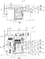
- Fig. 1 the reference numeral 1 generally shows an LED module according to a first embodiment of the present invention.
- the LED module 1 comprises a circuit 2 for controlling LED channels K1, K2 or for controlling LEDs L1, L2.
- the circuit 2 can be designed in the form of an integrated circuit, preferably as a microcontroller, ASIC or hybrid version thereof.
- the circuit 2 includes a supply input 4 for supplying the circuit 2 with voltage. Furthermore, the circuit 2 includes outputs that can be connected with LED drivers T1, T2. These outputs are used to output control values or reference values for controlling the respective LED drivers T1, T2. Such a drive value is e.g. a voltage value which serves as a reference for the corresponding LED driver T1, T2.
- the LED drivers T1, T2 are current sources which, on the output side, generate a current for the respective LED channel K1, K2 or for the respective LED L1, L2 as a function of the drive value supplied on the input side.
- the LED drivers T1, T2 are preferably configured as a constant current source, so that when a constant drive value on the input side is applied, the current generated remains constant or at least almost constant.
- the mixed light which is generated by the LEDs L1, L2 of the LED channels K1, K2, can be controlled in a targeted manner.
- the control values By changing the control values, the color location and preferably also the intensity of the mixed light can be changed. In the case of a white mixed light, in particular the color temperature can be changed in a targeted manner.
- each LED channel comprises LEDs of a single color.
- the intensity maximum of all LEDs of an LED channel can then be in the same wavelength range, for example.
- the first LED channel K1 may have monochromatic, eg red LEDs.
- the second LED channel K2 can have white LEDs, in particular phosphor-converted blue LEDs. As a result, for example, a white mixed light can be generated.
- the first LED channel may have different phosphor-converted white-emitting LEDs.
- the second LED channel may have one or more blue LEDs.
- Fig. 1 shows only one LED per LED channel K1, K2, several LEDs per LED channel can be provided according to the invention.
- the number of LED channels is also variable, not two, as in Fig. 1 shown, limited.
- three LED channels may be provided in the form of a red, a green and a blue LED channel having only red, green and blue LEDs. This combination also allows the production of a white mixed light. It can also be provided, for example, five LED channels. Thus, in a so-called. RGBWA LED module, the circuit 2 for driving LED channels with red, green, blue, white and amber LEDs are formed.
- the circuit 2 preferably comprises a control unit 3, a memory unit 5 and digital-to-analog converter DA1, DA2.
- a look-up table or look-up table is provided in each case, in which the characteristic curve light output / diode current for each LED channel K1, K2 and possibly also for different temperatures is stored.
- a look-up table stored in the storage unit 5 is shown. This table defines which diode currents or operating currents Ir, Iw are necessary for the LED channels K1, K2 in order to produce a mixed light with the desired color temperature of eg 4200 K.
- the memory unit 5 generally comprises a look-up table per color location or per color temperature, which is to be achieved with the aid of the LED module 1.
- the circuit 2 is designed to control the LED drivers T1, T2 with drive values such that the LED channels K1, K2 are operated with the operating currents Ir, Iw defined in the look-up table.
- the operating current Ir stored in the look-up table refers to the current for the LED channel K1 having red LEDs.
- the information regarding the operating current Iw refers to the current with which the white LEDs of the LED channel K2 are to be operated.
- control unit 3 can thus determine the respective drive value for the LED driver T1, T2 of each LED channel K1, K2.
- the drive value can cause a linear dimming of the LED driver T1, T2 to the effect that the operating current generated by the LED driver is constant for the connected LED channel and is between zero and a nominal drive current.
- the LED driver can be controlled by a pulse width modulation (PWM).
- PWM pulse width modulation
- the LED channel is then operated by a PWM modulated nominal drive current.
- the drive value determined by the control unit 3 represents the PWM signal and in particular the duty cycle of the PWM signal.
- the LED driver receives this drive value and generates the PWM modulated nominal drive current by modulating the nominal drive current with the PWM signal.
- both PWM signals and constant current values can be generated in accordance with the linear dimming for the LED channels.
- Different combinations of PWM dimming and amplitude dimming can be used in different areas of the dimming curve. Any spectral changes with the operating current of the LED are compensated by the look-up tables.
- a combined operation of the LED channels via a combination of a PWM control is provided together with the linear dimming.
- the control unit 3 can set a digital control value, which in turn is converted by the digital-to-analog converter DA1, DA2 into an analog control value.
- the digital-to-analog converters DA1, DA2 are preferably designed as an integrated circuit.
- only one value for the respective operating current Ir, Iw is stored for each color locus to be reached in the corresponding look-up table.
- Advantage of this embodiment is that the operating currents Ir, Iw without much effort, i. only by reading the table, can be determined. However, the actually achieved color location may differ from the color location default, since the brightness of LEDs varies with temperature.
- the value Ir, Iw of the operating current as a function of the temperature can be stored in the look-up table.
- individual points of the operating current-temperature curve are shown in the look-up table.
- the temperature to be considered is the operating temperature of the LED module 1 or the LEDs or the ambient temperature.
- the circuit 2 preferably has an input for receiving information relating to this temperature.
- the LED module 1 comprises a thermistor TH connected to this input.
- the analog temperature information measured at the thermistor TH is preferably forwarded to an analog-to-digital converter 24.
- the control unit 3 receives the digital temperature information and selects in the look-up table the corresponding values for the operating currents Ir, Iw of the LED channels K1, K2.
- the thermistor TH is just one example of how the temperature information can be measured or determined. Instead of a thermistor, alternative temperature-dependent components can also be used. such as a photoresistor, thermocouple, transistor, diode.
- control unit 3 determines a temperature of, for example, 10 ° C., for which operating currents are stored in the table, then the corresponding operating currents Ir (10 ° C.), Iw (10 ° C.) are selected. If no corresponding operating currents Ir, Iw are stored in the look-up table for the measured temperature, the control unit 3 can perform interpolation of the data of the look-up table in order to match the operating currents Ir, Iw that match the measured temperature to investigate. For example, a linear interpolation can be performed, which minimizes the computational effort, or even more complex interpolation, such as spline interpolation.
- control unit 3 can first search for the closest stored temperature to the measured temperature, and select the corresponding operating currents Ir, Iw: if, for example, 6 ° C. are measured, the control unit 3 looks in the look-up table of FIG Fig. 1 the temperature is 5 ° C and then selects the operating currents Ir (5 ° C), Iw (5 ° C).
- Fig. 1 shows a simple implementation of the invention in that there are two LED channels K1, K2, namely a monochrome, in particular red channel and a dye-converted white light channel.
- the look-up table ensures that, regardless of the temperature, a constant color locus of the generated red / white spectrum is always achieved. For discrete temperature values, in each case a characteristic curve for the red characteristic or a characteristic curve for the white channel is stored.
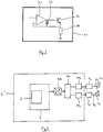
- Fig. 2 shows a further embodiment of an LED module according to the invention.
- the LED module 1 ' is based on the LED module 1 of Fig. 1 ,
- the LED module 1 comprises N LED channels K1, K2, K3, KN.
- memory 5 several look-up tables are stored, which are constructed similar to those in connection with Fig. 1 explained look-up table.
- Four look-up tables for a color temperature of 2500 K, 3500 K, 4200 K and 6500 K are stored.
- the look-up tables are not static, but may well undergo dynamic development in the course of, for example, the life of the LEDs or of the LED module. For example, a change in the values in the look-up tables may occur depending on the counted operating period of the LED module.
- a measuring unit 22 and an aging control unit 23 are provided in the LED module 1 '. Depending on the operating period of the LED module 1 'counted by the measuring unit 22, the aging control unit 23 causes a corresponding adaptation of the operating current values stored in the tables.
- the brightness of an LED may vary with time, so that it may be necessary to regulate the contribution that each LED channel makes to the mixed light, so that an overall characteristic of the LED produced mixed light still corresponds to the target color location.
- the measuring unit 22 measures the operating time of the LED module 1 '.
- the aging control unit 23 performs the adjustment of the operating current for each LED channel.
- a photodiode PH is preferably connected to the circuit.
- An analog-to-digital converter 25 converts the analog measurement signal from the photodiode PH into a digital signal, which is supplied to the control unit 3 '.
- the photodiode is here representative of a sensor for measuring the brightness or Umbegungshellmaschine. Instead of a photodiode, e.g. a phototransistor may also be provided.
- the operating current for the LED channels may be adjusted. For example, if the ambient brightness increases, the respective operating current for the LED channels can be increased or reduced.
- the ambient light adaptation carried out with the aid of the photodiode PH can be a color locus and luminous flux adaptation as a function of the ambient situation.
- the circuit 2 ' also has a digital interface 21.
- This interface 21 is connected to the control unit 3 'and is preferably configured bidirectionally.
- a look-up table can be sent from an external unit (not shown) via the digital interface 21 to the control unit 3 ', wherein this look-up table can in turn be stored in the memory unit 5. Otherwise, also in the storage unit 5 stored tables are sent via the interface 21 to an external unit.
- the adaptation of the operating currents which is caused in the course of aging of the LEDs or a change in the ambient brightness, can be influenced via the interface 21.
- the LED module 1 can be measured with spectrometer and / or color sensor. From this, the look-up tables are then discretized and stored in the memory unit 2 assigned to the circuit 2. These tables may preferably be for comparable LED modules, i. with comparable LED placement, are used and stored in the memory unit of these comparable LED modules.
- the LED module 1 can be characterized with regard to the LEDs used with reference to a maximum of three specified test points with regard to wavelength, intensity and color location. From the combination of the LEDs, the correct look-up tables LUTs can be created and stored from a data pool.
- an LED module can be optically and electrically measured according to the following criteria. For each target color location eg on the Plank curve or within the range spanned by the light sources, values for the operating currents for the LED channels determined. These values are only valid for one temperature. For this reason, further values for the operating currents are determined for different temperatures. This can be done, for example, by heating the carrier board of the LED module to the desired temperature. All determined values for a target color location are then stored in a look-up table in the memory unit 5.
- the look-up tables found in an initialization phase are stored in the memory of the circuit.
- Possible correction factors such as Lifetime degradation, linear dimming, etc., can also be stored as factors or formulas due to the known LED data.
- the correction factors relating to the LED aging or lifetime can be stored in the aging control unit 23 or alternatively in the control unit 3.
- the corresponding current values for a desired color location are stored in a look-up table as a function of the temperature on the basis of the measurement results.
- the corresponding current values are automatically adapted to the situation, which allows an accurate and reproducible color temperature to be achieved with the same luminous flux.
- Fig. 3 is an embodiment of an LED driver 30, as shown for example in an LED channel of the operating device according to Fig. 1 or Fig. 2 can be used.
- the LED driver 30 has an operational amplifier 31, to the input side of which the current-determining reference signal generated by the respective digital-to-analog converter DA1, DA2, DA3, DA4 is supplied.
- the second input and the output of the operational amplifier 31 are connected via a capacitor 32.
- the output of the operational amplifier 31 is connected to the control input of a transistor 33, which is a bipolar transistor or preferably a MOSFET.
- the emitter terminal of the transistor 33 is in turn connected to the second input of the operational amplifier 31.
- the capacitor 32 is connected in parallel to the base-emitter path of the transistor 33.
- a precision resistor 34 is connected between the emitter terminal and ground.
- the collector terminal of the transistor 33 is designed for connection to the LEDs of the respective LED channel.
- FIG. 4 A further embodiment is shown, in which the drive values for each LED driver T1, T2 are supplied in succession to a single digital-to-analog converter DA.
- This analog drive value is then fed to a further unit 40 in the form of preferably a demultiplexer, which is connected to a sample-and-hold circuit SH1, SH2 of the respective LED channel K1, K2. With the aid of this sample-and-hold circuit SH1, SH2, the starting values for each LED channel are recorded until the next change in the current value.
- a further unit 40 in the form of preferably a demultiplexer, which is connected to a sample-and-hold circuit SH1, SH2 of the respective LED channel K1, K2.
- SH1, SH2 With the aid of this sample-and-hold circuit SH1, SH2, the starting values for each LED channel are recorded until the next change in the current value.
- only one digital-to-analog converter DA is necessary.
- the subject invention now shows a clearer, more accurate and less computational and approximate effort associated achievement of a target color location.
- the invention enables a precise linear regulation or current dimming. Accordingly, no flickering and no disturbing dark stripes in TV or camera shots at the same color location or color temperature is caused.
- the invention relates to the achievement of a target color location.
- intensity values can also be stored in look-up tables.
- a linear dimming or a logarithmic dimming can be implemented.
- This logarithmic dimming is mapped, for example, into corresponding look-up tables, since the sensitivity of the human eye follows a logarithmic function.
- limited color vision, but still excellent light-dark vision (shades of gray) are made possible at very low magnitudes.
- a logarithmic dimming of the light-generating LED module is perceived as more pleasant and with higher acceptance compared to linear dimming.
Description
Die vorliegende Erfindung betrifft allgemein die Erzeugung einer Lichtfarbe durch Mischen des Lichts mehrerer Licht emittierender Dioden (LEDs). Genauer gesagt ist die Erfindung auf die Erzeugung von Mischlicht einer gewünschten Farbe und/oder einer gewünschten Farbtemperatur und auf die Steuerung von LEDs gerichtet, um das Licht mit der gewünschten Farbe bzw. der gewünschten Farbtemperatur durch Mischen des Lichts, das durch die betreffenden LEDs erzeugt wird, zu erzeugen bzw. erhalten.The present invention generally relates to the generation of a light color by mixing the light of multiple light emitting diodes (LEDs). More specifically, the invention is directed to the generation of mixed light of a desired color and / or color temperature and to the control of LEDs to produce the light of the desired color or color temperature by mixing the light produced by the respective LEDs is to generate or receive.
Im Stand der Technik ist es bereits bekannt, wie das farbige Licht, das von LEDs emittiert wird, gemessen und erfasst werden kann. Die Verfahren sind besonders nützlich, wenn angestrebt wird, die LEDs zu steuern und zu betreiben, um eine gewünschte Farbe oder eine gewünschte Intensität des Mischlichts zu erhalten.It is already known in the prior art how the colored light emitted by LEDs can be measured and detected. The methods are particularly useful when aiming to control and operate the LEDs to obtain a desired color or intensity of the mixed light.
Bekannte LED-Anordnungen umfassen eine Vielzahl von LEDs, die z.B. entsprechend dem RGB (rot-grün-blau)-Farbmodell angeordnet sind. Eine solche LED-Anordnung kann also LEDs mit drei verschiedenen Farben umfassen, vorzugsweise rot, grün und blau, die bei entsprechenden Wellenlängen emittieren. Diese bekannte LED-Anordnung kann insbesondere jede Farbe reproduzieren, die sich innerhalb des Farbdreiecks, das durch diese drei Farben - rot, grün und blau - begrenzt ist, in einem Farbwertdiagramm wie beispielsweise dem CIE 1931 Farbraum befindet.Known LED arrays include a plurality of LEDs, for example, arranged according to the RGB (red-green-blue) color model. Such an LED array can thus comprise LEDs with three different colors, preferably red, green and blue, which emit at appropriate wavelengths. In particular, this known LED array can reproduce any color that is within the color triangle bounded by these three colors - red, green and blue - in a color value chart such as the CIE 1931 color space.
Die
Bei einem solchen Stand der Technik wird mit den Tristimuluswerten über eine Matrixoperation analytisch ein Ansteuerwert für die unterschiedlichen LED-Typen bestimmt. Derzeit wird also der gesamte durch die z.B. drei oder vier LED-Typen aufgespannte Farbraum im CIE Farbraum über Transformation und Näherungsformeln in Strom- und PWM-Signal umgerechnet.In such a state of the art, an activation value for the different LED types is analytically determined with the tristimulus values via a matrix operation. At present, therefore, the whole is covered by the e.g. Three or four LED types spanned color space in the CIE color space converted into current and PWM signal via transformation and approximation formulas.
Aufgrund der Näherungsformeln und Schätzwerten ist bei einer derartigen analytischen Herangehensweise das Erreichen eines Zielfarbortes fehlerbehaftet und zudem nicht eindeutig.Due to the approximate formulas and estimates, the achievement of a target color location in such an analytical approach is flawed and also ambiguous.
Im Patentdokument
Diese Aufgabe wird erfindungsgemäß gelöst durch die Merkmale der unabhängigen Ansprüche. Die abhängigen Ansprüche bilden den zentralen Gedanken der Erfindung in besonders vorteilhafter Weise weiter.This object is achieved by the features of the independent claims. The dependent claims further form the central idea of the invention in a particularly advantageous manner.
Ein erster Aspekt der Erfindung bezieht sich auf eine Schaltung zur Ansteuerung von mehreren LED-Kanälen, aufweisend jeweils mindestens eine LED, und zur Erzeugung eines Mischlichts aus dem von den jeweiligen LED-Kanälen erzeugten Licht. Für jeden Zielfarbort des Mischlichts, der durch das LED-Modul erreichbar ist, ist jeweils eine Look-up-Tabelle vorgesehen, in der der Betriebsstrom für jeden LED-Kanal abgelegt ist.A first aspect of the invention relates to a circuit for driving a plurality of LED channels, each comprising at least one LED, and for generating a mixed light from the light generated by the respective LED channels. For each target color location of the mixed light, which can be reached by the LED module, a look-up table is provided in each case, in which the operating current is stored for each LED channel.
Ein weiterer Aspekt der Erfindung bezieht sich auf ein Verfahren zur Ansteuerung von mehreren LED-Kanälen, aufweisend jeweils mindestens eine LED, und zur Erzeugung eines Mischlichts aus dem von den jeweiligen LED-Kanälen erzeugten Licht. Für jeden Zielfarbort des Mischlichts, der durch das LED-Modul erreichbar ist, ist jeweils eine Look-up-Tabelle vorgesehen, in der der Betriebsstrom für jeden LED-Kanal abgelegt ist.Another aspect of the invention relates to a method for driving a plurality of LED channels, each having at least one LED, and for generating a mixed light from the light generated by the respective LED channels. For each target color location of the mixed light, which can be reached by the LED module, a look-up table is provided in each case, in which the operating current is stored for each LED channel.
Der Betriebsstrom kann in Abhängigkeit von der Temperatur gespeichert sein.The operating current can be stored as a function of the temperature.
Für jeden LED-Kanal können diskrete Werte einer Betriebsstrom/Temperatur-Kennlinie abgelegt sein.Discrete values of an operating current / temperature characteristic can be stored for each LED channel.
Die Schaltung kann dazu ausgebildet sein, abhängig von einer gemessenen Temperatur und ausgehend von der abgelegten Betriebsstrom/Temperatur-Kennlinie den jeweiligen Betriebsstrom für die LED-Kanäle zu ermitteln. Die Schaltung kann eine Steuereinheit aufweisen, die abhängig von der Look-up-Tabelle einen Ansteurwert für eine zum Betreiben eines LED-Kanals vorgesehene Stromquelle festlegt.The circuit may be designed to determine the respective operating current for the LED channels as a function of a measured temperature and based on the stored operating current / temperature characteristic. The circuit may have a control unit which, depending on the look-up table, determines an injection value for a current source provided for operating an LED channel.
Der Ansteuerwert kann derart ausgebildet sein, dass von der Stromquelle eine Dimmung auf einen konstanten Stromwert und/oder eine PWM-Modulierung eines Nominal-Betriebsstroms durchführbar ist.The control value can be designed such that a dimming to a constant current value and / or a PWM modulation of a nominal operating current can be carried out by the current source.
Die Schaltung kann einen Eingang für die Messung einer Umgebungstemperatur aufweisen, wobei dieser Eingang vorzugsweise an einem Thermistor angeschlossen ist.The circuit may have an input for measuring an ambient temperature, which input is preferably connected to a thermistor.
Die Schaltung kann einen Eingang für ein Messsignal eines Helligkeits-Sensors aufweisen, wobei abhängig von der gemessenen Helligkeit der jeweilige Betriebsstrom für den jeden LED-Kanal korrigiert wird.The circuit may have an input for a measurement signal of a brightness sensor, wherein, depending on the measured brightness, the respective operating current for each LED channel is corrected.
Abhängig von einer Betriebsdauer der Schaltung kann der jeweilige Betriebsstrom für den jeden LED-Kanal korrigiert werden.Depending on an operating time of the circuit, the respective operating current for each LED channel can be corrected.
Die Schaltung kann eine Kommunikationsschnittstelle aufweisen zum Empfangen von Look-up-Tabellen und / oder Korrekturwerten.The circuit may have a communication interface for receiving look-up tables and / or correction values.
Der Zielfarbort kann sich auf der Plank'schen Kurve oder innerhalb eines vorgegebenen Zielbereiches innerhalb des von den LEDs aufgespannten Bereichs befinden.The target color locus may be on the Plank curve or within a predetermined target area within the area spanned by the LEDs.
Die Schaltung kann mehrere Look-up-Tabellen zum Ansteuern von diskreten Werten auf der Plank'schen Weißlichtkurve aufweisen.The circuit may include a plurality of look-up tables for driving discrete values on the Plank white light curve.
Unterschiedliche Helligkeiten eines Zielfarborts können in Look-up-Tabellen abgelegt sein.Different brightnesses of a target color location can be stored in look-up tables.
Die Schaltung kann in Form einer integrierten Schaltung, vorzugsweise in Form eines Mikrocontroller, eines ASIC oder einer Hybridversion davon, ausgestaltet sein.The circuit may be in the form of an integrated circuit, preferably in the form of a microcontroller, an ASIC or a hybrid version thereof.
Ein weiterer Aspekt der Erfindung bezieht sich auf ein LED-Modul aufweisend eine derartige Schaltung.Another aspect of the invention relates to an LED module comprising such a circuit.
Weitere Aspekte, Merkmale und Eigenschaften der vorliegenden Erfindung werden aus der folgenden Beschreibung beispielhafter Ausführungsbeispiele und anhand der Figuren der begleitenden Zeichnungen näher erläutert.
-
Fig. 1 zeigt ein erstes Ausführungsbeispiel eines LED-Moduls gemäß der vorliegenden Erfindung. -
Fig. 2 zeigt ein zweites Ausführungsbeispiel eines erfindungsgemäßen LED-Moduls. -
Fig. 3 zeigt eine Ausführungsform eines erfindungsgemäßen LED-Treibers. -
Fig. 4 zeigt ein weiteres Ausführungsbeispiel eines erfindungsgemäßen LED-Treibers.
-
Fig. 1 shows a first embodiment of an LED module according to the present invention. -
Fig. 2 shows a second embodiment of an LED module according to the invention. -
Fig. 3 shows an embodiment of an LED driver according to the invention. -
Fig. 4 shows a further embodiment of an LED driver according to the invention.
In
Das LED-Modul 1 umfasst eine Schaltung 2 zur Steuerung von LED-Kanälen K1, K2 bzw. zur Steuerung von LEDs L1, L2. Die Schaltung 2 kann in Form einer integrierten Schaltung, vorzugsweise als Mikrocontroller, ASIC oder Hybridversion davon, ausgestaltet sein.The LED module 1 comprises a
Die Schaltung 2 enthält einen Versorgungseingang 4 zur Versorgung der Schaltung 2 mit Spannung. Weiterhin enthält die Schaltung 2 Ausgänge, die mit LED-Treibern T1, T2 anschliesbar sind. Diese Ausgänge dienen zur Ausgabe von Ansteuerwerten bzw. Referenzwerten zur Steuerung der jeweiligen LED-Treiber T1, T2. Ein derartiger Ansteuerwert ist z.B. ein Spannungswert, der als Referenz für den entsprechenden LED-Treiber T1, T2 dient.The
Die LED-Treiber T1, T2 sind Stromquellen, die abhängig von dem eingangsseitig zugeführten Ansteuerwert ausgangsseitig einen Strom für den jeweiligen LED-Kanal K1, K2 bzw. für die jeweilige LED L1, L2 erzeugen. Die LED-Treiber T1, T2 sind vorzugsweise als Konstantstromquelle ausgestaltet, so dass bei Anliegen eines eingangsseitigen konstanten Ansteuerwerts der erzeugte Strom konstant oder zumindest nahezu konstant bleibt.The LED drivers T1, T2 are current sources which, on the output side, generate a current for the respective LED channel K1, K2 or for the respective LED L1, L2 as a function of the drive value supplied on the input side. The LED drivers T1, T2 are preferably configured as a constant current source, so that when a constant drive value on the input side is applied, the current generated remains constant or at least almost constant.
Durch die Ausgabe von gezielten Ansteuerwerten für die jeweiligen LED-Treiber T1, T2 kann das Mischlicht, das von den LEDs L1, L2 der LED-Kanäle K1, K2 erzeugt wird, gezielt gesteuert werden. Durch eine Veränderung der Ansteuerwerte kann der Farbort und vorzugsweise auch die Intensität des Mischlichts geändert werden. Bei einem weißen Mischlicht kann insbesondere die Farbtemperatur gezielt geändert werden.By the output of targeted drive values for the respective LED drivers T1, T2, the mixed light, which is generated by the LEDs L1, L2 of the LED channels K1, K2, can be controlled in a targeted manner. By changing the control values, the color location and preferably also the intensity of the mixed light can be changed. In the case of a white mixed light, in particular the color temperature can be changed in a targeted manner.
Vorzugsweise umfasst jeder LED-Kanal LEDs einer einzigen Farbe. Das Intensitätsmaximum aller LEDs eines LED-Kanals kann sich dann beispielsweise im gleichen Wellenlängenbereich befinden. Im Ausführungsbeispiel der
Alternativ kann der erste LED-Kanal unterschiedliche phosphorkonvertierte weiß abstrahlende LEDs aufweisen. Der zweite LED-Kanal kann eine oder mehrere blaue LEDs aufweisen.Alternatively, the first LED channel may have different phosphor-converted white-emitting LEDs. The second LED channel may have one or more blue LEDs.
Auch wenn
Die Anzahl der LED-Kanäle ist ebenfalls variierbar und nicht auf zwei, wie in
Die Schaltung 2 umfasst vorzugsweise eine Steuereinheit 3, eine Speichereinheit 5 und Digital-Analog-Umsetzer DA1, DA2.The
Für jeden Farbort, der durch das LED-Modul 1 zu erreichen sein soll, ist jeweils eine Nachschlagtabelle oder Look-up-Tabelle vorgesehen, in der die Kennkurve Lichtoutput/Diodenstrom für jeden LED-Kanal K1, K2 und ggf. auch für unterschiedliche Temperaturen abgelegt ist.For each color location that is to be achieved by the LED module 1, a look-up table or look-up table is provided in each case, in which the characteristic curve light output / diode current for each LED channel K1, K2 and possibly also for different temperatures is stored.
In
Die Schaltung 2 ist dazu ausgelegt, die LED-Treiber T1, T2 derart mit Ansteuerwerten zu steuern, dass die LED-Kanäle K1, K2 mit den in der Look-up-Tabelle definierten Betriebsströmen Ir, Iw betrieben werden. Z.B. bezieht sich der in der Look-up-Tabelle abgespeicherte Betriebsstrom Ir auf den Strom für den LED-Kanal K1 aufweisend rote LEDs. Die Information bzgl. des Betriebsstroms Iw bezieht sich auf den Strom, mit dem die weißen LEDs des LED-Kanals K2 betrieben werden sollen.The
Ausgehend von dieser bzw. von diesen Look-up-Tabellen kann somit die Steuereinheit 3 den jeweiligen Ansteuerwert für den LED-Treiber T1, T2 eines jeden LED-Kanals K1, K2 festlegen.Based on this or these look-up tables, the
Der Ansteuerwert kann einerseits ein lineares Dimmen des LED-Treibers T1, T2 dahingehend verursachen, dass der vom LED-Treiber erzeugte Betriebsstrom für den angeschlossenen LED-Kanal konstant ist und zwischen Null und einem Nominal-Bestriebsstrom sich befindet.On the one hand, the drive value can cause a linear dimming of the LED driver T1, T2 to the effect that the operating current generated by the LED driver is constant for the connected LED channel and is between zero and a nominal drive current.
Andererseits kann der LED-Treiber durch eine Pulsweitenmodulation (PWM) angesteuert werden. Der LED-Kanal wird dann von einem PWM-modulierten Nominal-Bestriebsstrom betrieben. Der von der Steuereinheit 3 festgelegte Ansteuerwert gibt das PWM-Signal und insbesondere das Tastverhältnis des PWM-Signals wieder. Der LED-Treiber empfängt diesen Ansteuerwert und erzeugt den PWM-modulierten Nominal-Bestriebsstrom dadurch, dass der Nominal-Bestriebsstrom mit dem PWM-Signal moduliert wird.On the other hand, the LED driver can be controlled by a pulse width modulation (PWM). The LED channel is then operated by a PWM modulated nominal drive current. The drive value determined by the
Erfindungsgemäß können somit sowohl PWM-Signale als auch konstante Stromwerte gemäß dem linearen Dimmen für die LED-Kanäle erzeugt werden. In unterschiedlichen Bereichen der Dimmkurve können unterschiedliche Kombinationen an PWM-Dimmen und Amplitudendimmen verwendet werden. Eventuelle spektrale Veränderungen mit dem Betriebsstrom der LED werden durch die Look-Up-Tables kompensiert.Thus, according to the invention, both PWM signals and constant current values can be generated in accordance with the linear dimming for the LED channels. Different combinations of PWM dimming and amplitude dimming can be used in different areas of the dimming curve. Any spectral changes with the operating current of the LED are compensated by the look-up tables.
Alternativ ist auch ein kombinierter Betrieb der LED-Kanäle über eine Kombination einer PWM-Steuerung zusammen mit dem linearen Dimmen vorgesehen.Alternatively, a combined operation of the LED channels via a combination of a PWM control is provided together with the linear dimming.
Die Steuereinheit 3 kann einen digitalen Ansteuerwert festlegen, der wiederum durch den Digital-Analog-Umsetzer DA1, DA2 in einen analogen Ansteuerwert umgesetzt wird. Die Digital-Analog-Umsetzer DA1, DA2 werden vorzugsweise als integrierter Schaltkreis ausgeführt.The
Nach einem Ausführungsbeispiel der Erfindung ist für jeden zu erreichenden Farbort in der entsprechenden Look-up-Tabelle lediglich ein Wert für den jeweiligen Betriebsstrom Ir, Iw abgespeichert. Vorteil dieses Ausführungsbeispiel ist, dass die Betriebsströme Ir, Iw ohne großen Aufwand, d.h. nur durch Ablesen der Tabelle, ermittelt werden können. Allerdings kann der tatsächlich erzielte Farbort von der Farbort-Vorgabe abweichen, da die Helligkeit von LEDs mit der Temperatur variiert.According to one embodiment of the invention, only one value for the respective operating current Ir, Iw is stored for each color locus to be reached in the corresponding look-up table. Advantage of this embodiment is that the operating currents Ir, Iw without much effort, i. only by reading the table, can be determined. However, the actually achieved color location may differ from the color location default, since the brightness of LEDs varies with temperature.
Alternativ und wie im Ausführungsbeispiel der
Die Schaltung 2 weist vorzugsweise einen Eingang zum Empfang einer Information betreffend dieser Temperatur auf. Wie in
Ermittelt die Steuereinheit 3 eine Temperatur von z.B. 10°C, für die in der Tabelle Betriebsströme gespeichert sind, so werden die entsprechende Betriebsströme Ir(10°C), Iw(10°C) ausgewählt. Falls in der Look-up-Tabelle für die gemessene Temperatur keine entsprechenden Betriebsströme Ir, Iw abgespeichert sind, kann von der Steuereinheit 3 eine Interpolation der Daten der Look-up-Tabelle durchgeführt werden, um die für die gemessene Temperatur passenden Betriebsströme Ir, Iw zu ermitteln. Es kann z.B. eine lineare Interpolation durchgeführt werden, wodurch der Rechenaufwand gering gehalten wird, oder auch eine komplexere Interpolation wie z.B. die Spline-Interpolation. Alternativ zu einer Interpolation kann die Steuereinheit 3 zunächst die nächstliegende abgespeicherte Temperatur zu der gemessenen Temperatur suchen, und die entsprechenden Betriebsströme Ir, Iw auswählen: werden z.B. 6°C gemessen, so sucht die Steueeinheit 3 in der Look-up-Tabelle der
Das LED-Modul 1' umfasst N LED-Kanäle K1, K2, K3, KN. Im Speicher 5 sind mehrere Look-up-Tabellen abgelegt, die ähnlich aufgebaut sind, wie die in Zusammenhang mit
Gemäß einem weiteren Aspekt der Erfindung sind die Look-up-Tabellen nicht statisch, sondern können durchaus im Laufe beispielsweise der Lebensdauer der LEDs bzw. des LED-Moduls einer dynamischen Entwicklung unterzogen werden. Beispielsweise kann eine Veränderung der Werte in den Look-up-Tabellen abhängig von der gezählten Betriebszeitdauer des LED-Moduls stattfinden. Hierfür sind im LED-Modul 1' eine Messungseinheit 22 und eine Alterungssteuereinheit 23 vorgesehen. Abhängig von der von der Messungseinheit 22 gezählten Betriebszeitdauer des LED-Moduls 1' veranlasst die Alterungssteuereinheit 23 eine entsprechende Anpassung der in den Tabellen gespeicherten Betriebstromwerte.According to a further aspect of the invention, the look-up tables are not static, but may well undergo dynamic development in the course of, for example, the life of the LEDs or of the LED module. For example, a change in the values in the look-up tables may occur depending on the counted operating period of the LED module. For this purpose, a measuring
Tatsächlich kann die Helligkeit einer LED mit der Zeit variieren, so dass es notwendig sein kann, den Beitrag, den jeder LED-Kanal zu dem gemischten Licht leistet, zu regulieren, so dass eine Gesamtcharakteristik des erzeugten gemischten Lichts immer noch dem Zielfarbort entspricht.In fact, the brightness of an LED may vary with time, so that it may be necessary to regulate the contribution that each LED channel makes to the mixed light, so that an overall characteristic of the LED produced mixed light still corresponds to the target color location.
Um sicher zu stellen, dass die erzeugte Eigenschaft des gemischten Lichts mit der Zeit konstant bleibt, misst die Messungseinheit 22 die Betriebsdauer des LED-Moduls 1'. Die Alterungssteuereinheit 23 führt für jeden LED-Kanal die Anpassung des Betriebsstroms durch.In order to ensure that the generated property of the mixed light remains constant over time, the measuring
Eine Photodiode PH ist vorzugsweise mit der Schaltung verbunden. Ein Analog-Digital-Umsetzer 25 wandelt das analoge Messsignal von der Photodiode PH in ein digitales Signal, das der Steuereinheit 3' zugeführt wird. Die Photodiode ist hier stellvertretend für einen Sensor zum Messen der Helligkeit bzw. der Umbegungshelligkeit. Statt einer Photodiode kann z.B. auch ein Phototransistor vorgesehen sein. Abhängig von der gemessenen Helligkeit kann der Betriebsstrom für die LED-Kanäle angepasst sein. Z.B. wenn die Umgebungshelligkeit steigt, kann auch der jeweilige Betriebsstrom für die LED-Kanäle erhöht oder reduziert werden. Die mit Hilfe der Photodiode PH durchgeführte Umgebungslichtadaption kann eine Farbort- und Lichtstromanpassung in Abhängigkeit der Umgebungssituation sein.A photodiode PH is preferably connected to the circuit. An analog-to-
Die Schaltung 2' weist auch eine digitale Schnittstelle 21 auf. Diese Schnittstelle 21 ist mit der Steuereinheit 3' verbunden und ist vorzugsweise bidirektional ausgestaltet. Somit kann eine Look-up-Tabelle von einer externen Einheit (nicht gezeigt) über die digitale Schnittstelle 21 zur Steuereinheit 3' gesendet werden, wobei diese Look-up-Tabelle wiederum in der Speichereinheit 5 abgespeichert werden kann. Andersrum können auch in der Speichereinheit 5 abgespeicherte Tabellen über die Schnittstelle 21 zu einer externen Einheit gesendet werden.The circuit 2 'also has a
Auch die Anpassung der Betriebsströme, die im Zuge einer Alterung der LEDs oder einer Veränderung der Umgebungshelligkeit veranlasst wird, kann über die Schnittstelle 21 beeinflusst werden.Also, the adaptation of the operating currents, which is caused in the course of aging of the LEDs or a change in the ambient brightness, can be influenced via the
Im Folgenden wird erläutert, wie die Look-up-Tabellen erstellt werden.The following explains how to create the lookup tables.
Um die Werte für die Look-up-Tabellen zu bestimmen, kann das LED-Modul 1 mit Spektrometer und/oder Farbsensor vermessen werden. Daraus werden dann diskretisiert die Look-up-Tabellen erstellt und in der der Schaltung 2 zugeordneten Speichereinheit 5 abgelegt. Diese Tabellen können vorzugsweise für vergleichbare LED-Module, d.h. mit vergleichbarer LED-Bestückung, benutzt werden und in der Speichereinheit dieser vergleichbaren LED-Module abgelegt werden.In order to determine the values for the look-up tables, the LED module 1 can be measured with spectrometer and / or color sensor. From this, the look-up tables are then discretized and stored in the
Zur Bestimmung der Look-up-Tabellen kann das LED-Modul 1 hinsichtlich verwendeter LEDs anhand von maximal drei spezifizierten Testpunkten hinsichtlich Wellenlänge, Intensität und Farbort charakterisiert werden. Aus der Kombination der LEDs lassen sich aus einem Datenpool die richtigen Look-up-Tabellen LUTs erstellen und abspeichern.To determine the look-up tables, the LED module 1 can be characterized with regard to the LEDs used with reference to a maximum of three specified test points with regard to wavelength, intensity and color location. From the combination of the LEDs, the correct look-up tables LUTs can be created and stored from a data pool.
In einer Initialisierungsphase nach Fertigung des LED-Moduls kann also ein LED-Modul nach folgenden Gesichtspunkten optisch und elektrisch vermessen werden. Für jeden Zielfarbort z.B. auf der Plank'schen Kurve oder innerhalb des von den Lichtquellen aufgespannten Bereichs werden Werte für die Betriebsströme für die LED-Kanäle ermittelt. Diese Werte sind allerdings nur für eine Temperatur gültig. Deswegen werden für verschiedene Temperaturen weitere Werte für die Betriebsströme ermittelt. Dies kann z.B. durch Erwärmung der Trägerplatine des LED-Moduls auf die gewünschte Temperatur erfolgen. Alle ermittelten Werte für einen Zielfarbort werden anschließend in einer Look-up-Tabelle in der Speichereinheit 5 abgelegt.In an initialization phase after production of the LED module, therefore, an LED module can be optically and electrically measured according to the following criteria. For each target color location eg on the Plank curve or within the range spanned by the light sources, values for the operating currents for the LED channels determined. These values are only valid for one temperature. For this reason, further values for the operating currents are determined for different temperatures. This can be done, for example, by heating the carrier board of the LED module to the desired temperature. All determined values for a target color location are then stored in a look-up table in the
Die in einer Initialisierungsphase gefundenen Look-up-Tabellen werden im Speicher der Schaltung abgelegt. Eventuelle Korrekturfaktoren, wie z.B. Lebensdauerdegradation, lineare Dimmung, etc., können aufgrund der bekannten LED-Daten als Faktoren oder Formeln ebenfalls abgespeichert werden. Z.B. können die Korrekturfaktoren betreffend die LED-Alterung bzw. - Lebensdauer in der Alterungssteuereinheit 23 abgespeichert werden oder alternativ in der Steuereinheit 3.The look-up tables found in an initialization phase are stored in the memory of the circuit. Possible correction factors, such as Lifetime degradation, linear dimming, etc., can also be stored as factors or formulas due to the known LED data. For example, For example, the correction factors relating to the LED aging or lifetime can be stored in the aging
Im einfachsten Fall der Initialisierung und Steuerung des LED-Moduls (z. Bsp. RW-Kombination) werden aufgrund der Vermessungsergebnisse die entsprechenden Stromwerte für einen gewünschten Farbort in einer Look- Up-Tabelle in Abhängigkeit der Temperatur gespeichert. Über eine Temperaturmessung direkt am Modul werden nun die entsprechenden Stromwerte automatisch der Situation angepasst, wodurch sich eine akkurate und reproduzierbare Farbtemperatur bei gleichbleibendem Lichtstrom realisieren lässt.In the simplest case of the initialization and control of the LED module (eg RW combination), the corresponding current values for a desired color location are stored in a look-up table as a function of the temperature on the basis of the measurement results. By measuring the temperature directly at the module, the corresponding current values are automatically adapted to the situation, which allows an accurate and reproducible color temperature to be achieved with the same luminous flux.
In
Der LED-Treiber 30 weist einen Operationsverstärker 31 auf, dem eingangsseitig das von dem jeweiligen Digital-Analog-Umsetzer DA1, DA2, DA3, DA4 erzeugte strombestimmende Referenzsignal zugeführt wird. Der zweite Eingang und der Ausgang des Operationsverstärkers 31 sind über einen Kondensator 32 verbunden.The
Der Ausgang des Operationsverstärkers 31 ist an den Steuereingang eines Transistors 33, angeschlossen, der ein Bipolartransistor oder vorzugsweise ein MOSFET ist. Der Emitter-Anschluss des Transistors 33 ist wiederum am zweiten Eingang des Operationsverstärkers 31 angeschlossen. Somit ist der Kondensator 32 in parallel zur Basis-Emitter-Strecke des Transistors 33 geschaltet. Weiterhin ist noch ein Präzisions-Widerstand 34 zwischen dem Emitter-Anschluss und Masse verschaltet. Der Kollektor-Anschluss des Transistors 33 ist dabei zum Verbinden mit den LEDs des jeweiligen LED-Kanals ausgelegt.The output of the
In
Die gegenständliche Erfindung zeigt nun eine eindeutigere, exaktere und mit weniger Rechen- und Näherungsaufwand verbundene Erreichung eines Zielfarborts.The subject invention now shows a clearer, more accurate and less computational and approximate effort associated achievement of a target color location.
Für das Erreichen eines Zielfarborts sind im Gegensatz zum Stand der Technik keine aufwändigen und komplexen Algorithmen und Transformationen notwendig.In contrast to the prior art, no complex and complex algorithms and transformations are necessary for achieving a target color location.
Dadurch ermöglicht die Erfindung eine präzise lineare Regelung bzw. Stromdimmung. Entsprechend wird kein Flackern und keine störenden Dunkelstreifen bei TV bzw. Kameraaufnahmen bei gleichbleibendem Farbort bzw. Farbtemperatur verursacht.As a result, the invention enables a precise linear regulation or current dimming. Accordingly, no flickering and no disturbing dark stripes in TV or camera shots at the same color location or color temperature is caused.
Die Erfindung bezieht sich auf die Erreichung eines Zielfarborts. Zusätzlich können in Look-up-Tabellen auch Intensitätswerte mit abgespeichert werden. So kann eindeutig und reproduzierbar der gleiche Farbort mit unterschiedlichen Lichtströmen dargestellt werden. Dadurch ist eine lineare Dimmung oder auch eine logarithmische Dimmung umsetzbar. Diese logarithmische Dimmung ist z.B. in entsprechende Look-Up-Tabellen abgebildet, da die Empfindlichkeit des menschlichen Auges einer logarithmischen Funktion folgt. Insbesondere werden dadurch bei sehr geringen Helligkeiten zwar eingeschränktes Farbsehen, aber noch ausgezeichnetes Hell-Dunkel-Sehen (Grauschattierungen) ermöglicht. Eine logarithmische Dimmung des lichterzeugenden LED-Moduls wird im Vergleich zur linearen Dimmung als angenehmer und mit höherer Akzeptanz wahr- und angenommen.The invention relates to the achievement of a target color location. In addition, intensity values can also be stored in look-up tables. Thus, the same color locus with different luminous fluxes can be clearly and reproducibly displayed. As a result, a linear dimming or a logarithmic dimming can be implemented. This logarithmic dimming is mapped, for example, into corresponding look-up tables, since the sensitivity of the human eye follows a logarithmic function. In particular, limited color vision, but still excellent light-dark vision (shades of gray) are made possible at very low magnitudes. A logarithmic dimming of the light-generating LED module is perceived as more pleasant and with higher acceptance compared to linear dimming.
-
1 LED-Modul (das LED-Modul selbst muss in der gegenständlichen Erfindung nicht zwingend als Gesamtsystem ausgeführt sein, vielmehr besteht die Möglichkeit, dass L1, L2 bis Ln als LED-Modul ausgeführt sind, während die Schaltung 2 getrennt vom LED-Modul und modular aufgebaut sein kann1 LED module (the LED module itself does not necessarily have to be designed as an overall system in the subject invention, but rather there is the possibility that L1, L2 to Ln are designed as an LED module, while the
circuit 2 separated from the LED module and can be modular - 2 Schaltung2 circuit
- 3 Steuereinheit3 control unit
- 4 Versorgungseingang4 supply input
- 5 Speichereinheit5 storage unit
- 21 digitale Schnittstelle21 digital interface
- 22 Messungseinheit22 measuring unit
- 23 Alterungssteuereinheit23 aging control unit
- 24 Analog-Digital-Umsetzer24 analog-to-digital converter
- 25 Analog-Digital-Umsetzer25 analog-to-digital converter
- 30 LED-Treiber30 LED drivers
- 31 Operationsverstärker31 operational amplifiers
- 32 Kondensator32 capacitor
- 33 Transistor33 transistor
- 34 Widerstand34 resistance
- 40 Multiplexer40 multiplexers
- DA1... Digital-Analog-UmsetzerDA1 ... digital-to-analog converter
- K1... LED-KanalK1 ... LED channel
- L1... LEDL1 ... LED
- PH PhotodiodePH photodiode
- SH1 Sample-and-Hold-SchaltungSH1 sample-and-hold circuit
- T1... LED-TreiberT1 ... LED driver
- TH ThermistorTH thermistor
Claims (13)
- A circuit (2) for controlling a plurality of LED channels (K1, K2) in each case having at least one LED (L1, L2) and for generating mixed light from the light generated by the respective LED channels (K1, K2),
wherein for each target color locus, which can be reached by the LED module, in each case a look-up table is provided, which is stored in a storage unit (5) of the circuit, in which the operating current (Ir, Iw) for each LED channel (K1, K2) is stored,
wherein for each LED channel(K1, K2) discrete values of an operating current/ temperature characteristic curve are stored, and
wherein the circuit is designed to determine the respective operating current for the LED channels (K1, K2) depending on a measured temperature and based on the stored operating current/temperature characteristic curve,
wherein the circuit is also designed to correct the respective operating current for each LED channel (K1, K2) depending on an operating time of the circuit, wherein the circuit has a measurement unit (22) and an aging control unit (23), and wherein depending on an operating period of time of the LED module (1) counted by the measurement unit (22) the aging control unit (23) causes a corresponding adjustment of the operating current values recorded in the tables. - A circuit according to Claim 1,
wherein the operating current (Ir, Iw) is stored depending on the temperature. - A circuit according to Claim 1 or 2,
having a control unit (3), which depending on the look-up table sets a control value for a current source (T1, T2) provided for operating a LED channel (K1, K2). - A circuit according to Claim 3,
wherein the control value is designed in such a manner that a dimming to a constant current value and/or a PWM (pulse width modulated) modulation of a nominal operating current can be carried out by the current source (T1, T2). - A circuit according to any one of the preceding claims,
having an input for measuring an ambient temperature, wherein said input preferably is connected to a temperature sensitive element, for example, a Thermistor (TH). - A circuit according to any one of the preceding claims,
having an input for a measurement signal of a brightness sensor (PH), wherein depending on the measured brightness the respective operating current is corrected or changed for each LED channel (K1, K2). - A circuit according to any one of the preceding claims
having a communications interface (21) for receiving look-up tables. - A circuit according to any one of the preceding claims,
wherein the target color locus is located on the Plankian curve or within a predetermined target range within the area spanned by the LEDs (L1, L2). - A circuit according to any one of the preceding claims
having a plurality of look-up tables for controlling discrete values on the Plankian white-light curve. - A circuit according to anyone of the preceding claims,
wherein different brightnesses of a target color locus are stored in look-up tables. - A circuit according to any one of the preceding claims in the form of an integrated circuit, preferably in the form of a microcontroller, an ASIC or a hybrid version thereof.
- A LED module having a circuit according to any one of the preceding claims.
- A method for controlling a plurality of LED channels (K1, K2) having in each case at least one LED (L1, L2) and for generating a mixed light from light generated by the respective LED channels (K1, K2),
wherein for each target color locus, which can be reached by the LED module, in each case a look-up table is provided, in which the operating current (Ir, Iw) is recorded for each LED channel,
wherein for each LED channel (K1, K2) discrete values of an operating current/temperature characteristic curve are stored, and wherein depending on a measured temperature and based on the stored operating current/temperature characteristic curve the respective operating current is determined for the LED channels (K1, K2),
wherein depending on an operating time of a circuit the respective operating current is corrected for each LED channel (K1, K2), and wherein the circuit has a measurement unit (22) and an aging control unit (23), and wherein depending on an operating period of time of the LED module (1) counted by a measurement unit (22) an aging control unit (23) causes a corresponding adjustment of the operating current values recorded in the tables.
Applications Claiming Priority (3)
| Application Number | Priority Date | Filing Date | Title |
|---|---|---|---|
| DE102012219900 | 2012-10-31 | ||
| DE102013201915.7A DE102013201915A1 (en) | 2012-10-31 | 2013-02-06 | Method and arrangement for controlling LEDs |
| PCT/EP2013/072160 WO2014067830A1 (en) | 2012-10-31 | 2013-10-23 | Method and arrangement for the temperature-corrected control of leds using look-up tables |
Publications (2)
| Publication Number | Publication Date |
|---|---|
| EP2901815A1 EP2901815A1 (en) | 2015-08-05 |
| EP2901815B1 true EP2901815B1 (en) | 2018-07-11 |
Family
ID=50555995
Family Applications (1)
| Application Number | Title | Priority Date | Filing Date |
|---|---|---|---|
| EP13788707.1A Active EP2901815B1 (en) | 2012-10-31 | 2013-10-23 | Method and arrangement for the temperature-corrected control of leds using look-up tables |
Country Status (3)
| Country | Link |
|---|---|
| EP (1) | EP2901815B1 (en) |
| DE (1) | DE102013201915A1 (en) |
| WO (1) | WO2014067830A1 (en) |
Families Citing this family (12)
| Publication number | Priority date | Publication date | Assignee | Title |
|---|---|---|---|---|
| DE102016104440A1 (en) * | 2016-03-10 | 2017-09-14 | Inova Semiconductors Gmbh | Method and device for brightness compensation of an LED |
| DE102016207725A1 (en) | 2016-05-04 | 2017-11-09 | Bayerische Motoren Werke Aktiengesellschaft | lighting device |
| DE102016207728A1 (en) | 2016-05-04 | 2017-11-09 | Bayerische Motoren Werke Aktiengesellschaft | lighting device |
| DE102016207727A1 (en) | 2016-05-04 | 2017-11-09 | Bayerische Motoren Werke Aktiengesellschaft | lighting device |
| DE102016207729A1 (en) | 2016-05-04 | 2017-11-09 | Bayerische Motoren Werke Aktiengesellschaft | lighting device |
| DE102016221772A1 (en) | 2016-11-07 | 2018-05-09 | Bayerische Motoren Werke Aktiengesellschaft | Lighting device and lighting system for a motor vehicle and method for operating a lighting system for a motor vehicle |
| DE102016221771A1 (en) | 2016-11-07 | 2018-05-09 | Bayerische Motoren Werke Aktiengesellschaft | Lighting device and lighting system for a motor vehicle and method for operating a lighting system for a motor vehicle |
| DE102017110170A1 (en) * | 2017-05-11 | 2018-11-15 | Osram Oled Gmbh | METHOD FOR OPERATING A VEHICLE LIGHT AND A VEHICLE LIGHT |
| DE102018004826A1 (en) * | 2018-06-15 | 2019-12-19 | Inova Semiconductors Gmbh | Method and system arrangement for setting a constant wavelength |
| DE102019208347A1 (en) * | 2019-06-07 | 2020-12-10 | Volkswagen Aktiengesellschaft | Method for operating a light-emitting diode module and light-emitting diode module |
| US11432385B2 (en) * | 2020-08-07 | 2022-08-30 | Analog Devices, Inc. | Single comparator exponential-scale PWM dimming |
| DE102020132948A1 (en) * | 2020-12-10 | 2022-06-15 | OSRAM Opto Semiconductors Gesellschaft mit beschränkter Haftung | OPTOELECTRONIC MODULE AND METHOD FOR MANUFACTURING OPTOELECTRONIC MODULE |
Citations (3)
| Publication number | Priority date | Publication date | Assignee | Title |
|---|---|---|---|---|
| US20100207534A1 (en) * | 2007-10-09 | 2010-08-19 | Philips Solid-State Lighting Solutions, Inc. | Integrated led-based luminare for general lighting |
| US20100301777A1 (en) * | 2007-09-07 | 2010-12-02 | Regine Kraemer | Method and Device For Adjusting the Color or Photometric Properties of an Led Illumination Device |
| DE102010000672A1 (en) * | 2010-01-05 | 2011-07-07 | Tridonic Ag | Combined method for operating an electrical lamp and operating circuit |
Family Cites Families (8)
| Publication number | Priority date | Publication date | Assignee | Title |
|---|---|---|---|---|
| US7740371B1 (en) * | 1998-03-19 | 2010-06-22 | Charles A. Lemaire | Method and apparatus for pulsed L.E.D. illumination for a camera |
| JP2005107059A (en) * | 2003-09-29 | 2005-04-21 | Sanyo Electric Co Ltd | Display device |
| KR101245121B1 (en) * | 2005-06-10 | 2013-03-25 | 에이저 시스템즈 엘엘시 | Regulation of electrical current through a resistive load |
| DE102008016756A1 (en) | 2008-03-31 | 2009-10-01 | Tridonicatco Schweiz Ag | Arrangement and method for controlling LEDs |
| WO2010016002A1 (en) * | 2008-08-06 | 2010-02-11 | Nxp B.V. | Dimming lighting devices |
| WO2010046811A1 (en) * | 2008-10-20 | 2010-04-29 | Philips Intellectual Property & Standards Gmbh | A method and an electronic device for improving the optical uniformity of tiled oled lighting sources |
| US8710754B2 (en) * | 2011-09-12 | 2014-04-29 | Juno Manufacturing Llc | Dimmable LED light fixture having adjustable color temperature |
| US9089032B2 (en) * | 2012-02-13 | 2015-07-21 | Lumenetix, Inc. | System and method for color tuning light output from an LED-based lamp |
-
2013
- 2013-02-06 DE DE102013201915.7A patent/DE102013201915A1/en not_active Withdrawn
- 2013-10-23 WO PCT/EP2013/072160 patent/WO2014067830A1/en active Application Filing
- 2013-10-23 EP EP13788707.1A patent/EP2901815B1/en active Active
Patent Citations (3)
| Publication number | Priority date | Publication date | Assignee | Title |
|---|---|---|---|---|
| US20100301777A1 (en) * | 2007-09-07 | 2010-12-02 | Regine Kraemer | Method and Device For Adjusting the Color or Photometric Properties of an Led Illumination Device |
| US20100207534A1 (en) * | 2007-10-09 | 2010-08-19 | Philips Solid-State Lighting Solutions, Inc. | Integrated led-based luminare for general lighting |
| DE102010000672A1 (en) * | 2010-01-05 | 2011-07-07 | Tridonic Ag | Combined method for operating an electrical lamp and operating circuit |
Also Published As
| Publication number | Publication date |
|---|---|
| WO2014067830A1 (en) | 2014-05-08 |
| EP2901815A1 (en) | 2015-08-05 |
| DE102013201915A1 (en) | 2014-05-15 |
Similar Documents
| Publication | Publication Date | Title |
|---|---|---|
| EP2901815B1 (en) | Method and arrangement for the temperature-corrected control of leds using look-up tables | |
| EP1938667B1 (en) | Light source emitting multi-coloured light and method for controlling the colour location of such a light source | |
| DE60219504T2 (en) | LED CONTROL DEVICE | |
| EP1643227B1 (en) | Illumination device and regulation method | |
| DE102008050818A1 (en) | Lighting and color management system | |
| TWI443630B (en) | Electroluminescent device aging compensation with reference subpixels | |
| EP2701464B1 (en) | Apparatus and method for producing light of a predetermined spectrum with at least four light sources of different colours | |
| EP2177078B1 (en) | Device and method for controlling light emission | |
| DE102007059130A1 (en) | Method and arrangement for setting a color location and luminous system | |
| EP2433472B1 (en) | Method for setting a chromaticity coordinate | |
| DE102005024449A1 (en) | lamp | |
| DE202005020801U1 (en) | Lamp for use in building, has electrically erasable programmable ROM registering data set describing characteristics of LEDs, where data set contains information e.g. about maximum, measured luminous flux of LEDs | |
| WO2015051963A1 (en) | Method and control device for operating at least one light source | |
| DE102008029816A1 (en) | Circuit for dimming a lamp and associated method | |
| DE102010028406A1 (en) | LED lighting device and method for operating an LED lighting device | |
| DE102017125405B4 (en) | Method and device for calibrating and operating RGB-LED lighting | |
| WO2008071235A1 (en) | Led module with dedicated colour regulation and corresponding method | |
| DE102015009736A1 (en) | Light module and lighting system | |
| DE102011079796B4 (en) | Method for determining PWM values for LED modules | |
| DE102012208172A1 (en) | LED driver with color monitoring | |
| DE102007004834A1 (en) | Light device and method for realizing a desired color mixture | |
| DE102009031403A1 (en) | Light-emitting element for use in lamp, has sensors and controller formed as optical window and arranged on semiconductor substrate, and interface provided for adjustment of light intensity and/or chromaticity coordinates | |
| DE102015110003A1 (en) | Method for controlling a lighting device, method for determining control signal information for the control and lighting device | |
| DE102017219853A1 (en) | Illuminable control for a household appliance | |
| DE102006010999A1 (en) | Illumination system and method for operating a lighting system |
Legal Events
| Date | Code | Title | Description |
|---|---|---|---|
| PUAI | Public reference made under article 153(3) epc to a published international application that has entered the european phase |
Free format text: ORIGINAL CODE: 0009012 |
|
| 17P | Request for examination filed |
Effective date: 20141020 |
|
| AK | Designated contracting states |
Kind code of ref document: A1 Designated state(s): AL AT BE BG CH CY CZ DE DK EE ES FI FR GB GR HR HU IE IS IT LI LT LU LV MC MK MT NL NO PL PT RO RS SE SI SK SM TR |
|
| AX | Request for extension of the european patent |
Extension state: BA ME |
|
| DAX | Request for extension of the european patent (deleted) | ||
| STAA | Information on the status of an ep patent application or granted ep patent |
Free format text: STATUS: EXAMINATION IS IN PROGRESS |
|
| 17Q | First examination report despatched |
Effective date: 20161110 |
|
| GRAP | Despatch of communication of intention to grant a patent |
Free format text: ORIGINAL CODE: EPIDOSNIGR1 |
|
| STAA | Information on the status of an ep patent application or granted ep patent |
Free format text: STATUS: GRANT OF PATENT IS INTENDED |
|
| INTG | Intention to grant announced |
Effective date: 20180315 |
|
| GRAA | (expected) grant |
Free format text: ORIGINAL CODE: 0009210 |
|
| STAA | Information on the status of an ep patent application or granted ep patent |
Free format text: STATUS: THE PATENT HAS BEEN GRANTED |
|
| AK | Designated contracting states |
Kind code of ref document: B1 Designated state(s): AL AT BE BG CH CY CZ DE DK EE ES FI FR GB GR HR HU IE IS IT LI LT LU LV MC MK MT NL NO PL PT RO RS SE SI SK SM TR |
|
| REG | Reference to a national code |
Ref country code: GB Ref legal event code: FG4D Free format text: NOT ENGLISH |
|
| REG | Reference to a national code |
Ref country code: CH Ref legal event code: EP |
|
| REG | Reference to a national code |
Ref country code: AT Ref legal event code: REF Ref document number: 1018319 Country of ref document: AT Kind code of ref document: T Effective date: 20180715 |
|
| GRAS | Grant fee paid |
Free format text: ORIGINAL CODE: EPIDOSNIGR3 |
|
| REG | Reference to a national code |
Ref country code: IE Ref legal event code: FG4D Free format text: LANGUAGE OF EP DOCUMENT: GERMAN |
|
| REG | Reference to a national code |
Ref country code: DE Ref legal event code: R096 Ref document number: 502013010605 Country of ref document: DE |
|
| REG | Reference to a national code |
Ref country code: FR Ref legal event code: PLFP Year of fee payment: 6 |
|
| REG | Reference to a national code |
Ref country code: NL Ref legal event code: MP Effective date: 20180711 |
|
| REG | Reference to a national code |
Ref country code: LT Ref legal event code: MG4D |
|
| PG25 | Lapsed in a contracting state [announced via postgrant information from national office to epo] |
Ref country code: NL Free format text: LAPSE BECAUSE OF FAILURE TO SUBMIT A TRANSLATION OF THE DESCRIPTION OR TO PAY THE FEE WITHIN THE PRESCRIBED TIME-LIMIT Effective date: 20180711 |
|
| PG25 | Lapsed in a contracting state [announced via postgrant information from national office to epo] |
Ref country code: NO Free format text: LAPSE BECAUSE OF FAILURE TO SUBMIT A TRANSLATION OF THE DESCRIPTION OR TO PAY THE FEE WITHIN THE PRESCRIBED TIME-LIMIT Effective date: 20181011 Ref country code: GR Free format text: LAPSE BECAUSE OF FAILURE TO SUBMIT A TRANSLATION OF THE DESCRIPTION OR TO PAY THE FEE WITHIN THE PRESCRIBED TIME-LIMIT Effective date: 20181012 Ref country code: RS Free format text: LAPSE BECAUSE OF FAILURE TO SUBMIT A TRANSLATION OF THE DESCRIPTION OR TO PAY THE FEE WITHIN THE PRESCRIBED TIME-LIMIT Effective date: 20180711 Ref country code: SE Free format text: LAPSE BECAUSE OF FAILURE TO SUBMIT A TRANSLATION OF THE DESCRIPTION OR TO PAY THE FEE WITHIN THE PRESCRIBED TIME-LIMIT Effective date: 20180711 Ref country code: FI Free format text: LAPSE BECAUSE OF FAILURE TO SUBMIT A TRANSLATION OF THE DESCRIPTION OR TO PAY THE FEE WITHIN THE PRESCRIBED TIME-LIMIT Effective date: 20180711 Ref country code: LT Free format text: LAPSE BECAUSE OF FAILURE TO SUBMIT A TRANSLATION OF THE DESCRIPTION OR TO PAY THE FEE WITHIN THE PRESCRIBED TIME-LIMIT Effective date: 20180711 Ref country code: PL Free format text: LAPSE BECAUSE OF FAILURE TO SUBMIT A TRANSLATION OF THE DESCRIPTION OR TO PAY THE FEE WITHIN THE PRESCRIBED TIME-LIMIT Effective date: 20180711 Ref country code: IS Free format text: LAPSE BECAUSE OF FAILURE TO SUBMIT A TRANSLATION OF THE DESCRIPTION OR TO PAY THE FEE WITHIN THE PRESCRIBED TIME-LIMIT Effective date: 20181111 Ref country code: BG Free format text: LAPSE BECAUSE OF FAILURE TO SUBMIT A TRANSLATION OF THE DESCRIPTION OR TO PAY THE FEE WITHIN THE PRESCRIBED TIME-LIMIT Effective date: 20181011 |
|
| PGFP | Annual fee paid to national office [announced via postgrant information from national office to epo] |
Ref country code: AT Payment date: 20181025 Year of fee payment: 6 |
|
| PG25 | Lapsed in a contracting state [announced via postgrant information from national office to epo] |
Ref country code: AL Free format text: LAPSE BECAUSE OF FAILURE TO SUBMIT A TRANSLATION OF THE DESCRIPTION OR TO PAY THE FEE WITHIN THE PRESCRIBED TIME-LIMIT Effective date: 20180711 Ref country code: ES Free format text: LAPSE BECAUSE OF FAILURE TO SUBMIT A TRANSLATION OF THE DESCRIPTION OR TO PAY THE FEE WITHIN THE PRESCRIBED TIME-LIMIT Effective date: 20180711 Ref country code: LV Free format text: LAPSE BECAUSE OF FAILURE TO SUBMIT A TRANSLATION OF THE DESCRIPTION OR TO PAY THE FEE WITHIN THE PRESCRIBED TIME-LIMIT Effective date: 20180711 Ref country code: HR Free format text: LAPSE BECAUSE OF FAILURE TO SUBMIT A TRANSLATION OF THE DESCRIPTION OR TO PAY THE FEE WITHIN THE PRESCRIBED TIME-LIMIT Effective date: 20180711 |
|
| REG | Reference to a national code |
Ref country code: DE Ref legal event code: R097 Ref document number: 502013010605 Country of ref document: DE |
|
| PG25 | Lapsed in a contracting state [announced via postgrant information from national office to epo] |
Ref country code: EE Free format text: LAPSE BECAUSE OF FAILURE TO SUBMIT A TRANSLATION OF THE DESCRIPTION OR TO PAY THE FEE WITHIN THE PRESCRIBED TIME-LIMIT Effective date: 20180711 Ref country code: RO Free format text: LAPSE BECAUSE OF FAILURE TO SUBMIT A TRANSLATION OF THE DESCRIPTION OR TO PAY THE FEE WITHIN THE PRESCRIBED TIME-LIMIT Effective date: 20180711 Ref country code: CZ Free format text: LAPSE BECAUSE OF FAILURE TO SUBMIT A TRANSLATION OF THE DESCRIPTION OR TO PAY THE FEE WITHIN THE PRESCRIBED TIME-LIMIT Effective date: 20180711 Ref country code: IT Free format text: LAPSE BECAUSE OF FAILURE TO SUBMIT A TRANSLATION OF THE DESCRIPTION OR TO PAY THE FEE WITHIN THE PRESCRIBED TIME-LIMIT Effective date: 20180711 |
|
| PLBE | No opposition filed within time limit |
Free format text: ORIGINAL CODE: 0009261 |
|
| STAA | Information on the status of an ep patent application or granted ep patent |
Free format text: STATUS: NO OPPOSITION FILED WITHIN TIME LIMIT |
|
| PG25 | Lapsed in a contracting state [announced via postgrant information from national office to epo] |
Ref country code: SK Free format text: LAPSE BECAUSE OF FAILURE TO SUBMIT A TRANSLATION OF THE DESCRIPTION OR TO PAY THE FEE WITHIN THE PRESCRIBED TIME-LIMIT Effective date: 20180711 Ref country code: SM Free format text: LAPSE BECAUSE OF FAILURE TO SUBMIT A TRANSLATION OF THE DESCRIPTION OR TO PAY THE FEE WITHIN THE PRESCRIBED TIME-LIMIT Effective date: 20180711 Ref country code: DK Free format text: LAPSE BECAUSE OF FAILURE TO SUBMIT A TRANSLATION OF THE DESCRIPTION OR TO PAY THE FEE WITHIN THE PRESCRIBED TIME-LIMIT Effective date: 20180711 |
|
| REG | Reference to a national code |
Ref country code: CH Ref legal event code: PL |
|
| 26N | No opposition filed |
Effective date: 20190412 |
|
| REG | Reference to a national code |
Ref country code: BE Ref legal event code: MM Effective date: 20181031 |
|
| PG25 | Lapsed in a contracting state [announced via postgrant information from national office to epo] |
Ref country code: MC Free format text: LAPSE BECAUSE OF FAILURE TO SUBMIT A TRANSLATION OF THE DESCRIPTION OR TO PAY THE FEE WITHIN THE PRESCRIBED TIME-LIMIT Effective date: 20180711 Ref country code: LU Free format text: LAPSE BECAUSE OF NON-PAYMENT OF DUE FEES Effective date: 20181023 |
|
| REG | Reference to a national code |
Ref country code: IE Ref legal event code: MM4A |
|
| PG25 | Lapsed in a contracting state [announced via postgrant information from national office to epo] |
Ref country code: LI Free format text: LAPSE BECAUSE OF NON-PAYMENT OF DUE FEES Effective date: 20181031 Ref country code: SI Free format text: LAPSE BECAUSE OF FAILURE TO SUBMIT A TRANSLATION OF THE DESCRIPTION OR TO PAY THE FEE WITHIN THE PRESCRIBED TIME-LIMIT Effective date: 20180711 Ref country code: CH Free format text: LAPSE BECAUSE OF NON-PAYMENT OF DUE FEES Effective date: 20181031 Ref country code: BE Free format text: LAPSE BECAUSE OF NON-PAYMENT OF DUE FEES Effective date: 20181031 |
|
| REG | Reference to a national code |
Ref country code: DE Ref legal event code: R084 Ref document number: 502013010605 Country of ref document: DE |
|
| PG25 | Lapsed in a contracting state [announced via postgrant information from national office to epo] |
Ref country code: IE Free format text: LAPSE BECAUSE OF NON-PAYMENT OF DUE FEES Effective date: 20181023 |
|
| REG | Reference to a national code |
Ref country code: DE Ref legal event code: R079 Ref document number: 502013010605 Country of ref document: DE Free format text: PREVIOUS MAIN CLASS: H05B0033080000 Ipc: H05B0045000000 |
|
| PG25 | Lapsed in a contracting state [announced via postgrant information from national office to epo] |
Ref country code: MT Free format text: LAPSE BECAUSE OF FAILURE TO SUBMIT A TRANSLATION OF THE DESCRIPTION OR TO PAY THE FEE WITHIN THE PRESCRIBED TIME-LIMIT Effective date: 20180711 |
|
| PGFP | Annual fee paid to national office [announced via postgrant information from national office to epo] |
Ref country code: FR Payment date: 20191025 Year of fee payment: 7 |
|
| PG25 | Lapsed in a contracting state [announced via postgrant information from national office to epo] |
Ref country code: TR Free format text: LAPSE BECAUSE OF FAILURE TO SUBMIT A TRANSLATION OF THE DESCRIPTION OR TO PAY THE FEE WITHIN THE PRESCRIBED TIME-LIMIT Effective date: 20180711 |
|
| PG25 | Lapsed in a contracting state [announced via postgrant information from national office to epo] |
Ref country code: PT Free format text: LAPSE BECAUSE OF FAILURE TO SUBMIT A TRANSLATION OF THE DESCRIPTION OR TO PAY THE FEE WITHIN THE PRESCRIBED TIME-LIMIT Effective date: 20180711 |
|
| PG25 | Lapsed in a contracting state [announced via postgrant information from national office to epo] |
Ref country code: CY Free format text: LAPSE BECAUSE OF FAILURE TO SUBMIT A TRANSLATION OF THE DESCRIPTION OR TO PAY THE FEE WITHIN THE PRESCRIBED TIME-LIMIT Effective date: 20180711 Ref country code: HU Free format text: LAPSE BECAUSE OF FAILURE TO SUBMIT A TRANSLATION OF THE DESCRIPTION OR TO PAY THE FEE WITHIN THE PRESCRIBED TIME-LIMIT; INVALID AB INITIO Effective date: 20131023 Ref country code: MK Free format text: LAPSE BECAUSE OF NON-PAYMENT OF DUE FEES Effective date: 20180711 |
|
| REG | Reference to a national code |
Ref country code: AT Ref legal event code: MM01 Ref document number: 1018319 Country of ref document: AT Kind code of ref document: T Effective date: 20191023 |
|
| PG25 | Lapsed in a contracting state [announced via postgrant information from national office to epo] |
Ref country code: AT Free format text: LAPSE BECAUSE OF NON-PAYMENT OF DUE FEES Effective date: 20191023 |
|
| PGFP | Annual fee paid to national office [announced via postgrant information from national office to epo] |
Ref country code: GB Payment date: 20201027 Year of fee payment: 8 |
|
| PG25 | Lapsed in a contracting state [announced via postgrant information from national office to epo] |
Ref country code: FR Free format text: LAPSE BECAUSE OF NON-PAYMENT OF DUE FEES Effective date: 20201031 |
|
| REG | Reference to a national code |
Ref country code: DE Ref legal event code: R081 Ref document number: 502013010605 Country of ref document: DE Owner name: TRIDONIC GMBH & CO KG, AT Free format text: FORMER OWNER: TRIDONIC JENNERSDORF GMBH, JENNERSDORF, AT |
|
| GBPC | Gb: european patent ceased through non-payment of renewal fee |
Effective date: 20211023 |
|
| PG25 | Lapsed in a contracting state [announced via postgrant information from national office to epo] |
Ref country code: GB Free format text: LAPSE BECAUSE OF NON-PAYMENT OF DUE FEES Effective date: 20211023 |
|
| PGFP | Annual fee paid to national office [announced via postgrant information from national office to epo] |
Ref country code: DE Payment date: 20220527 Year of fee payment: 10 |
|
| P01 | Opt-out of the competence of the unified patent court (upc) registered |
Effective date: 20230530 |