EP2901607B1 - Colokationsanzeige für csi-rs und dmrs - Google Patents
Colokationsanzeige für csi-rs und dmrs Download PDFInfo
- Publication number
- EP2901607B1 EP2901607B1 EP13803230.5A EP13803230A EP2901607B1 EP 2901607 B1 EP2901607 B1 EP 2901607B1 EP 13803230 A EP13803230 A EP 13803230A EP 2901607 B1 EP2901607 B1 EP 2901607B1
- Authority
- EP
- European Patent Office
- Prior art keywords
- csi
- location
- user equipment
- behaviour
- resource
- Prior art date
- Legal status (The legal status is an assumption and is not a legal conclusion. Google has not performed a legal analysis and makes no representation as to the accuracy of the status listed.)
- Active
Links
- 230000005540 biological transmission Effects 0.000 claims description 69
- 230000011664 signaling Effects 0.000 claims description 37
- 230000007774 longterm Effects 0.000 claims description 35
- 238000000034 method Methods 0.000 claims description 32
- 239000002131 composite material Substances 0.000 claims description 12
- 108091006146 Channels Proteins 0.000 description 139
- 230000006399 behavior Effects 0.000 description 95
- 238000004891 communication Methods 0.000 description 23
- 230000009471 action Effects 0.000 description 19
- 230000006870 function Effects 0.000 description 13
- 230000008901 benefit Effects 0.000 description 8
- 238000005516 engineering process Methods 0.000 description 6
- 238000013507 mapping Methods 0.000 description 6
- 238000010586 diagram Methods 0.000 description 5
- 238000013461 design Methods 0.000 description 4
- 230000002452 interceptive effect Effects 0.000 description 4
- 238000005259 measurement Methods 0.000 description 4
- 230000006978 adaptation Effects 0.000 description 3
- 238000010295 mobile communication Methods 0.000 description 3
- 238000012545 processing Methods 0.000 description 3
- 238000012360 testing method Methods 0.000 description 3
- 101000741965 Homo sapiens Inactive tyrosine-protein kinase PRAG1 Proteins 0.000 description 2
- 102100038659 Inactive tyrosine-protein kinase PRAG1 Human genes 0.000 description 2
- 101150071746 Pbsn gene Proteins 0.000 description 2
- 230000002776 aggregation Effects 0.000 description 2
- 238000004220 aggregation Methods 0.000 description 2
- 230000001413 cellular effect Effects 0.000 description 2
- 125000004122 cyclic group Chemical group 0.000 description 2
- 230000000694 effects Effects 0.000 description 2
- 238000007726 management method Methods 0.000 description 2
- 230000007246 mechanism Effects 0.000 description 2
- 230000000737 periodic effect Effects 0.000 description 2
- 230000004044 response Effects 0.000 description 2
- 241000760358 Enodes Species 0.000 description 1
- 101150070878 Ereg gene Proteins 0.000 description 1
- 101100070120 Xenopus laevis has-rs gene Proteins 0.000 description 1
- 230000004913 activation Effects 0.000 description 1
- 230000009286 beneficial effect Effects 0.000 description 1
- 230000015556 catabolic process Effects 0.000 description 1
- 230000001427 coherent effect Effects 0.000 description 1
- 238000006731 degradation reaction Methods 0.000 description 1
- 230000001419 dependent effect Effects 0.000 description 1
- 238000011161 development Methods 0.000 description 1
- 230000002349 favourable effect Effects 0.000 description 1
- 230000006872 improvement Effects 0.000 description 1
- 230000003993 interaction Effects 0.000 description 1
- 238000012423 maintenance Methods 0.000 description 1
- 239000011159 matrix material Substances 0.000 description 1
- 239000000203 mixture Substances 0.000 description 1
- 230000008569 process Effects 0.000 description 1
- 238000011002 quantification Methods 0.000 description 1
- 238000013468 resource allocation Methods 0.000 description 1
- 238000000926 separation method Methods 0.000 description 1
- 238000001228 spectrum Methods 0.000 description 1
- 230000008685 targeting Effects 0.000 description 1
- 238000010200 validation analysis Methods 0.000 description 1
Images


Classifications
-
- H—ELECTRICITY
- H04—ELECTRIC COMMUNICATION TECHNIQUE
- H04W—WIRELESS COMMUNICATION NETWORKS
- H04W72/00—Local resource management
- H04W72/20—Control channels or signalling for resource management
- H04W72/23—Control channels or signalling for resource management in the downlink direction of a wireless link, i.e. towards a terminal
-
- H—ELECTRICITY
- H04—ELECTRIC COMMUNICATION TECHNIQUE
- H04L—TRANSMISSION OF DIGITAL INFORMATION, e.g. TELEGRAPHIC COMMUNICATION
- H04L25/00—Baseband systems
- H04L25/02—Details ; arrangements for supplying electrical power along data transmission lines
- H04L25/0202—Channel estimation
- H04L25/0204—Channel estimation of multiple channels
-
- H—ELECTRICITY
- H04—ELECTRIC COMMUNICATION TECHNIQUE
- H04L—TRANSMISSION OF DIGITAL INFORMATION, e.g. TELEGRAPHIC COMMUNICATION
- H04L25/00—Baseband systems
- H04L25/02—Details ; arrangements for supplying electrical power along data transmission lines
- H04L25/0202—Channel estimation
- H04L25/0222—Estimation of channel variability, e.g. coherence bandwidth, coherence time, fading frequency
-
- H—ELECTRICITY
- H04—ELECTRIC COMMUNICATION TECHNIQUE
- H04L—TRANSMISSION OF DIGITAL INFORMATION, e.g. TELEGRAPHIC COMMUNICATION
- H04L25/00—Baseband systems
- H04L25/02—Details ; arrangements for supplying electrical power along data transmission lines
- H04L25/0202—Channel estimation
- H04L25/0224—Channel estimation using sounding signals
- H04L25/0228—Channel estimation using sounding signals with direct estimation from sounding signals
-
- H—ELECTRICITY
- H04—ELECTRIC COMMUNICATION TECHNIQUE
- H04L—TRANSMISSION OF DIGITAL INFORMATION, e.g. TELEGRAPHIC COMMUNICATION
- H04L5/00—Arrangements affording multiple use of the transmission path
- H04L5/003—Arrangements for allocating sub-channels of the transmission path
- H04L5/0048—Allocation of pilot signals, i.e. of signals known to the receiver
-
- H—ELECTRICITY
- H04—ELECTRIC COMMUNICATION TECHNIQUE
- H04L—TRANSMISSION OF DIGITAL INFORMATION, e.g. TELEGRAPHIC COMMUNICATION
- H04L5/00—Arrangements affording multiple use of the transmission path
- H04L5/003—Arrangements for allocating sub-channels of the transmission path
- H04L5/0053—Allocation of signaling, i.e. of overhead other than pilot signals
- H04L5/0057—Physical resource allocation for CQI
-
- H—ELECTRICITY
- H04—ELECTRIC COMMUNICATION TECHNIQUE
- H04L—TRANSMISSION OF DIGITAL INFORMATION, e.g. TELEGRAPHIC COMMUNICATION
- H04L5/00—Arrangements affording multiple use of the transmission path
- H04L5/0091—Signaling for the administration of the divided path
- H04L5/0094—Indication of how sub-channels of the path are allocated
-
- H—ELECTRICITY
- H04—ELECTRIC COMMUNICATION TECHNIQUE
- H04L—TRANSMISSION OF DIGITAL INFORMATION, e.g. TELEGRAPHIC COMMUNICATION
- H04L25/00—Baseband systems
- H04L25/02—Details ; arrangements for supplying electrical power along data transmission lines
- H04L25/0202—Channel estimation
-
- H—ELECTRICITY
- H04—ELECTRIC COMMUNICATION TECHNIQUE
- H04L—TRANSMISSION OF DIGITAL INFORMATION, e.g. TELEGRAPHIC COMMUNICATION
- H04L5/00—Arrangements affording multiple use of the transmission path
- H04L5/0001—Arrangements for dividing the transmission path
- H04L5/0003—Two-dimensional division
- H04L5/0005—Time-frequency
- H04L5/0007—Time-frequency the frequencies being orthogonal, e.g. OFDM(A), DMT
- H04L5/001—Time-frequency the frequencies being orthogonal, e.g. OFDM(A), DMT the frequencies being arranged in component carriers
-
- H—ELECTRICITY
- H04—ELECTRIC COMMUNICATION TECHNIQUE
- H04L—TRANSMISSION OF DIGITAL INFORMATION, e.g. TELEGRAPHIC COMMUNICATION
- H04L5/00—Arrangements affording multiple use of the transmission path
- H04L5/003—Arrangements for allocating sub-channels of the transmission path
- H04L5/0032—Distributed allocation, i.e. involving a plurality of allocating devices, each making partial allocation
- H04L5/0035—Resource allocation in a cooperative multipoint environment
Definitions
- Embodiments herein relate to a user equipment, a radio network node and methods therein. In particular embodiments herein relate to performing channel estimation of one or more long term channel properties at the user equipment.
- wireless terminals also known as mobile stations and/or user equipments (UEs) communicate via a Radio Access Network (RAN) to one or more core networks.
- the radio access network covers a geographical area which is divided into cell areas, with each cell area being served by a base station, e.g., a Radio Base Station (RBS), which in some networks may also be called, for example, a "NodeB" or "eNodeB".
- RBS Radio Base Station
- a cell is a geographical area where radio coverage is provided by the radio base station at a base station site or an antenna site in case the antenna and the radio base station are not co-located.
- Each cell is identified by an identity within the local radio area, which is broadcast in the cell. Another identity identifying the cell uniquely in the whole mobile network is also broadcasted in the cell.
- the base stations communicate over the radio interface operating on radio frequencies with the user equipments within range of the base stations.
- UMTS Universal Mobile Telecommunications System
- GSM Global System for Mobile Communications
- UTRAN wideband code division multiple access
- HSPA High Speed Packet Access
- the Evolved Packet System comprises the Evolved Universal Terrestrial Radio Access Network (E-UTRAN), also known as the Long Term Evolution (LTE) radio access, and the Evolved Packet Core (EPC), also known as System Architecture Evolution (SAE) core network.
- E-UTRAN/LTE is a variant of a 3GPP radio access technology wherein the radio base station nodes are directly connected to the EPC core network rather than to RNCs.
- the functions of a RNC are distributed between the radio base stations nodes, e.g., eNodeBs in LTE, and the core network.
- the RAN of an EPS has an essentially "flat" architecture comprising radio base station nodes without reporting to RNCs.
- heterogeneous networks a mixture of cells of differently sized and overlapping coverage areas are deployed.
- pico cells are deployed within the coverage area of a macro cell.
- Other examples of low power nodes, also referred to as points, in heterogeneous networks are home base stations and relays.
- the aim of deploying low power nodes such as pico base stations within the macro coverage area is to improve system capacity by means of cell splitting gains as well as to provide users with wide area experience of very high speed data access throughout the network.
- Heterogeneous deployments are in particular effective to cover traffic hotspots, i.e. small geographical areas with high user densities served by e.g. pico cells, and they represent an alternative deployment to denser macro networks.
- LTE is a Frequency Division Multiplexing technology wherein Orthogonal Frequency Division Multiplexing (OFDM) is used in a Downlink (DL) transmission from a radio base station to a user equipment.
- OFDM Orthogonal Frequency Division Multiplexing
- SC-FDMA Single Carrier - Frequency Domain Multiple Access
- UL uplink
- Services in LTE are supported in the packet switched domain.
- the SC-FDMA used in the UL is also referred to as Discrete Fourier Transform Spread (DFTS) - OFDM.
- DFTS Discrete Fourier Transform Spread
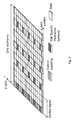
- the basic LTE downlink physical resource can thus be seen as a time-frequency grid as illustrated in Figure 1 , where each Resource Element (RE) corresponds to one subcarrier during one OFDM symbol interval on a particular antenna port.
- An antenna port is defined such that the channel over which a symbol on the antenna port is conveyed can be inferred from the channel over which another symbol on the same antenna port is conveyed.
- a symbol interval comprises a cyclic prefix (cp), which cp is a prefixing of a symbol with a repetition of the end of the symbol to act as a guard band between symbols and/or facilitate frequency domain processing.
- Frequencies f or subcarriers having a subcarrier spacing ⁇ f are defined along an z-axis and symbols are defined along an x-axis.
- a subframe is divided into two slots, each of 0.5 ms time duration.
- the resource allocation in LTE is typically described in terms of Resource Blocks (RB), where a resource block corresponds to one slot of 0.5 ms in the time domain and 12 contiguous 15 kHz subcarriers in the frequency domain. Two in time consecutive resource blocks represent a resource block pair and corresponds to the time interval upon which scheduling operates.
- RB Resource Blocks
- Resource blocks are numbered in the frequency domain, starting with resource block 0 from one end of the system bandwidth.
- Transmissions in LTE are dynamically scheduled in each subframe where the base station transmits downlink assignments/uplink grants to certain UEs via the physical downlink control information such as Physical Downlink Control Channel (PDCCH) and enhanced PDCCH (ePDCCH).
- the PDCCHs are transmitted in the first OFDM symbol(s) in each subframe and spans, more or less, the whole system bandwidth.
- a UE that has decoded a downlink assignment, carried by a PDCCH knows which resource elements in the subframe that contain data aimed for the UE. Similarly, upon receiving an uplink grant, the UE knows which time/frequency resources it should transmit upon.
- data is carried by the physical downlink shared data link on Physical Downlink Shared Channel (PDSCH) and in the uplink the corresponding link is referred to as the physical uplink shared link Physical Uplink Shared Channel (PUSCH).
- PDSCH Physical Downlink Shared Channel
- PUSCH Physical Uplink Shared Channel
- ePDCCH enhanced downlink control signaling
- PDCCH Physical Downlink Control Signals
- DMRS Demodulation Reference Signals
- CRS Cell specific Reference Symbols
- Demodulation of sent data requires estimation of the radio channel which is done by using transmitted reference symbols (RS), i.e. symbols known by the receiver.
- RS transmitted reference symbols
- CRS are transmitted in all downlink subframes and in addition to assist downlink channel estimation they are also used for mobility measurements performed by the UEs. LTE also supports UE specific RS aimed only for assisting channel estimation for demodulation purposes.
- the downlink subframe also comprises CRS, which are known to the receiver and used for coherent demodulation of e.g. the control information.
- the resource elements used for control signaling are indicated with wave-formed lines
- resource elements used for data are indicated as white REs
- resource elements used for reference symbols are indicated with diagonal lines.
- Frequencies f or subcarriers are defined along an z-axis and symbols are defined along an x-axis.
- Figure 3 illustrates how the mapping of physical control/data channels and signals can be done on resource elements within a downlink subframe.
- the PDCCHs occupy the first out of three possible OFDM symbols, so in this particular case the mapping of data could start already at the second OFDM symbol.
- PCFICH Physical Control Format Indicator Channel
- Hybrid-ARQ Physical Hybrid Automatic Repeat Request
- HARQ Physical Hybrid Automatic Repeat Request
- ACK/NACK Acknowledgement/Non-Acknowledgement
- CRS are not the only reference symbols available in LTE.
- LTE Release-10 a new RS concept was introduced with separate UE specific RS for demodulation of PDSCH and RS for measuring the channel for the purpose of Channel State Information (CSI) feedback from the UE.
- the latter is referred to as CSI-RS.
- CSI-RS are not transmitted in every subframe and they are generally sparser in time and frequency than RS used for demodulation.
- CSI-RS transmissions may occur every 5th, 10th, 20th, 40th, or 80th subframe according to a Radio Resource Control (RRC) configured periodicity parameter and an RRC configured subframe offset.
- RRC Radio Resource Control
- a UE operating in connected mode can be requested by the base station to perform CSI reporting, e.g. reporting a suitable Rank Indicator (RI), one or more Precoding Matrix Indices (PMI) and a Channel Quality Indicator (CQI).
- RI Rank Indicator
- PMI Precoding Matrix Indices
- CQI Channel Quality Indicator
- Other types of CSI are also conceivable including explicit channel feedback and interference covariance feedback.
- the CSI feedback assists the base station in scheduling, including deciding the subframe and RBs for the transmission, which transmission scheme/precoder to use, as well as provides information on a proper user bit rate for the transmission, link adaptation.
- LTE both periodic and aperiodic CSI reporting is supported.
- the UE reports the CSI measurements on a configured periodical time basis on the physical uplink control signaling (PUCCH), whereas with aperiodic reporting the CSI feedback is transmitted on the PUSCH at pre-specified time instants after receiving the CSI grant from the base station.
- the base station can thus request CSI reflecting downlink radio conditions in a particular subframe.
- the CSI-RS utilizes an orthogonal cover code of length two to overlay two antenna ports on two consecutive REs. As seen, many different CSI-RS pattern are available. For the case of 2 CSI-RS antenna ports we see that there are 20 different patterns within a subframe. The corresponding number of patterns is 10 and 5 for 4 and 8 CSI-RS antenna ports, respectively. For Time Division Duplexing (TDD), some additional CSI-RS patterns are available.
- TDD Time Division Duplexing
- CSI-RS resource may be mentioned.
- a resource corresponds to a particular pattern present in a particular subframe.
- two different patterns in the same subframe or the same CSI-RS pattern but in different subframes in both cases constitute two separate CSI-RS resources.
- the CSI-RS patterns may also correspond to so-called zero-power CSI-RS, also referred to as muted REs.
- Zero-power CSI-RS corresponds to a CSI-RS pattern whose REs are silent, i.e., there is no transmitted signal on those REs.
- Such silent patterns are configured with a resolution corresponding to the 4 antenna port CSI-RS patterns.
- the smallest unit to silence corresponds to four REs.
- zero-power CSI-RS The purpose of zero-power CSI-RS is to raise the Signal to Interference plus Noise Ratio (SINR) for CSI-RS in a cell by configuring zero-power CSI-RS in interfering cells so that the REs otherwise causing the interference are silent.
- SINR Signal to Interference plus Noise Ratio
- a CSI-RS pattern in a certain cell is matched with a corresponding zero-power CSI-RS pattern in interfering cells.
- Raising the SINR level for CSI-RS measurements is particularly important in applications such as Coordinated Multi Point (CoMP) or in heterogeneous deployments.
- CoMP Coordinated Multi Point
- the UE is likely to need to measure the channel from non-serving cells and interference from the much stronger serving cell would in that case be devastating.
- Zero-power CSI-RS is also needed in heterogeneous deployments where zero-power CSI-RS in the macro-layer is configured so that it coincides with CSI-RS transmissions in the pico-layer. This avoids strong interference from macro nodes when UEs measure the channel to a pico node.
- the PDSCH is mapped around the REs occupied by CSI-RS and zero-power CSI-RS so it is important that both the network and the UE are assuming the same CSI-RS/zero power CSI-RS configuration or else the UE is unable to decode the PDSCH in subframes containing CSI-RS or their zero-power counterparts.
- Control messages transmitted over the radio link to users can be broadly classified as control messages or data messages.
- Control messages are used to facilitate the proper operation of the system as well as proper operation of each UE within the system.
- Control messages could include commands to control functions such as the transmitted power from a UE, signaling of RBs within which the data is to be received by the UE or transmitted from the UE and so on.
- control messages are the PDCCHs which for example carry scheduling information and power control messages, the Physical HARQ Indicator Channel (PHICH), which carries ACK/NACK in response to a previous uplink transmission and the Physical Broadcast Channel (PBCH) which carries system information.
- PDCCHs Physical HARQ Indicator Channel
- PBCH Physical Broadcast Channel
- PSS/SSS primary and secondary synchronization signals
- PSS/SSS can be seen as control signals with fixed locations and periodicity in time and frequency so that UEs that initially access the network can find them and synchronize.
- the PBCH is not scheduled by a PDCCH transmission but has a fixed location relative to the PSS and SSSs. Therefore can the UE receive the system information transmitted in broadcast channel (BCH) before it is able to read the PDCCH.
- BCH broadcast channel
- Control messages to UEs are demodulated using the common or cell-specific reference signals (CRS) hence they have a cell wide coverage to reach all UEs in the cell without having knowledge about their position.
- CRS cell-specific reference signals
- PSS and SSS which are stand-alone and does not need reception of CRS before demodulation.
- the first one to four OFDM symbols, depending on the configuration, in a subframe are reserved to contain such control information, see Figure 3 and figure 5 .
- Control messages could be categorized into those types of messages that need to be sent only to one UE, UE-specific control, and those that need to be sent to all UEs or some subset of UEs numbering more than one, common control, within the cell being covered by the eNB
- Control messages of PDCCH type are demodulated using CRS and transmitted in multiples of units called Control Channel Elements (CCE) where each CCE contains 36 REs.
- a PDCCH may have Aggregation Level (AL) of 1, 2, 4 or 8 CCEs to allow for link adaptation of the control message.
- each CCE is mapped to nine Resource Element Groups (REG) comprising four REs each. These REG are distributed over the whole system bandwidth to provide frequency diversity for a CCE.
- the PDCCH which consists of up to 8 CCEs, spans the entire system bandwidth in the first one to four OFDM symbols, depending on the configuration.
- Figure 5 discloses a mapping of 1 CCE belonging to a PDCCH to the control region which spans the whole system bandwidth.
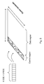
- Figure 6 shows a Downlink subframe showing 10 RB pairs and configuration of three ePDCCH regions, marked black, of size 1 Physical Resource Block (PRB) pair each. The remaining RB pairs can be used for PDSCH transmissions.
- PRB Physical Resource Block
- LTE Rel.11 it has been agreed to introduce UE-specific transmission for control information in form of enhanced control channels by allowing the transmission of generic control messages to a UE using such transmissions be based on UE-specific reference signals and by placement in the data region, see Figure 6 . This is commonly known as the enhanced PDCCH (ePDCCH), enhanced PHICH (ePHICH) and so on.
- ePDCCH enhanced PHICH
- ePHICH enhanced PHICH
- antenna port p ⁇ ⁇ 107,108,109,110 ⁇ for demodulation, see Figure 7 for normal subframes and normal cyclic prefix.
- Figure 7 shows an example of UE-specific reference symbols used for ePDCCH in LTE.
- R7 and R9 represent the DMRS corresponding to antenna port 107 and 109 respectively.
- antenna port 108 and 100 be obtained by applying an orthogonal cover as (1,-1) over adjacent pars of R7 and R9 respectively.
- This enhancement means that precoding gains can be achieved also for the control channels.
- Another benefit is that different PRB pairs, or enhanced control regions, see Figure 9 below, can be allocated to different cells or different transmission points within a cell, and thereby can inter-cell or inter-point interference coordination between control channels be achieved. This is especially useful for HetNet scenario as will be discussed in the next section.
- a point corresponds to a set of antennas covering essentially the same geographical area in a similar manner.
- a point might correspond to one of the sectors at a site, but it may also correspond to a site having one or more antennas all intending to cover a similar geographical area.
- different points represent different sites.
- Antennas correspond to different points when they are sufficiently geographically separated and/or having antenna diagrams pointing in sufficiently different directions.
- Techniques for CoMP entail introducing dependencies in the scheduling or transmission/reception among different points, in contrast to conventional cellular systems where a point from a scheduling point of view is operated more or less independently from the other points.
- DL CoMP operations may include, e.g., serving a certain UE from multiple points, either at different time instances or for a given subframe, on overlapping or not overlapping parts of the spectrum.
- Dynamic switching between transmission points serving a certain UE is often termed as Dynamic Point Selection (DPS).
- Simultaneously serving a UE from multiple points on overlapping resources is often termed as joint transmission (JT).
- JT joint transmission
- the point selection may be based, e.g., on instantaneous conditions of the channels, interference or traffic.
- CoMP operations are intended to be performed, e.g., for data channels such as PDSCH and/or control channels such as ePDCCH.
- the same enhanced control region can be used in different transmission points within a cell or belong to different cells, that are not highly interfering each other.
- a typical case is the shared cell scenario, where a macro cell contains lower power pico nodes within its coverage area, having (or being associated to) the same synchronization signal/cell ID, see Figure 8 .
- pico nodes which are geographically separated, as B and C in figure 8 the same enhanced control region, i.e. the same PRBs used for the ePDCCH can be re-used. In this manner the total control channel capacity in the shared cell will increase since a given PRB resource is re-used, potentially multiple times, in different parts of the cell. This ensures that area splitting gains are obtained.
- Figure 8 shows a heterogeneous network scenario where the dashed line indicates the macro cell coverage area and A,B and C corresponds to the coverage of three pico nodes.
- A,B,C and the macrocell have the same cell ID, e.g. the same synchronization signal, i.e. transmitted or being associated to the same synchronization signal.
- FIG. 9 An example is given in Figure 9 where pico node B and C share the enhanced control region whereas A, due to the proximity to B, is of risk of interfering with each other and is therefore assigned an enhanced control region which is non-overlapping. Interference coordination between pico nodes A and B, or equivalently transmission point A and B, within a shared cell is thereby achieved. In some cases, a UE may need to receive part of the control channel signaling from the macro cell and the other part of the control signaling from the nearby Pico cell.
- This area splitting and control channel frequency coordination is not possible with the PDCCH since the PDCCH spans the whole bandwidth.
- the PDCCH does not provide possibility to use UE specific precoding since it relies on the use of CRS for demodulation.
- Figure 10 shows an ePDCCH which, similar to the CCE in the PDCCH, is divided into multiple groups and mapped to one of the enhanced control regions. Note that in figure 10 , the enhanced control region does not start at OFDM symbol zero, to accommodate simultaneous transmission of a PDCCH in the subframe. However, as was mentioned above, there may be carrier types in future LTE releases that do not have a PDCCH, in which case the enhanced control region could start from OFDM symbol zero within the subframe.
- the enhanced control channel enables UE specific precoding and such localized transmission as illustrated in figure 10 , it can in some cases be useful to be able to transmit an enhanced control channel in a broadcasted, wide area coverage fashion. This is useful if the eNB does not have reliable information to perform precoding towards a certain UE, then a wide area coverage transmission is more robust.
- Another case is when the particular control message is intended to more than one UE, in this case UE specific precoding cannot be used.
- An example is the transmission of the common control information using PDCCH, i.e. in the common search space (CSS).
- Figure 11 shows a downlink subframe showing a CCE belonging to an ePDCCH is mapped to multiple of the enhanced control regions, to achieve distributed transmission and frequency diversity or subband precoding.
- DL CoMP One fundamental property of DL CoMP is the possibility to transmit different signals and/or channels from different geographical locations or points.
- One of the principles guiding the design of the LTE system is transparency of the network to the UE. In other words, the UE is able to demodulate and decode its intended channels without specific knowledge of scheduling assignments for other UEs or network deployments.
- DCI Downlink Control Information
- ePDCCH Downlink Control Information
- one application consists of distributing parts of the scheduling algorithm at different points, such that, e.g., DL transmissions are associated to a different point than UL transmissions. In such a case, it makes sense to schedule DL and UL transmissions with control signaling providing directly from the respective points.
- a further application consists of serving a UE with parallel data transmissions from different points, e.g., for increasing data rate or during handover between points.
- a further application consists of transmitting system control information from a "master" point and rely on data transmission from other points, typically associated to pico nodes.
- UEs are not aware of the geographical location from which each RS port is transmitted.
- DMRS or UE specific RS are employed for demodulation of data channels and possibly certain control channels, ePDCCH.
- UE specific RS relieves the UE from having to know many of the properties of the transmission and thus allows flexible transmission schemes to be used form the network side. This is referred to as transmission transparency, with respect to the UE.
- transmission transparency This is referred to as transmission transparency, with respect to the UE.
- a problem is however that the estimation accuracy of UE specific RS may not be good enough in some situations.
- Geographical separation of RS ports implies that instantaneous channel coefficients from each port towards the UE are in general different. Furthermore, even the statistical properties of the channels for different ports and RS types may be significantly different. Example of such statistical properties include the received power for each port, the delay spread, the Doppler spread, the received timing, i.e., the timing of the first significant channel tap, the number of significant channel taps, the frequency shift. In LTE, nothing can be assumed about the properties of the channel corresponding to an antenna port based on the properties of the channel of another antenna port. This is in fact key part of maintaining transmission transparency.
- the UE needs to perform independent estimation for each RS port of interest for each RS. This results in occasionally inadequate channel estimation quality for certain RS ports, leading to undesirable link and performance degradation of the radio communications network.
- An object according to embodiments herein is to provide a mechanism that improves the channel estimation process in a radio communications network.
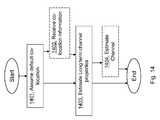
- the object is achieved by a method in a user equipment for performing channel estimation of one or more long term channel properties at the user equipment.
- the user equipment is served by a radio network node.
- the user equipment assumes that a default Channel State Information Reference Signal, CSI-RS, resource is co-located with a Demodulation Reference signal, DMRS, port when co-location is not explicitly signalled from the radio network node.
- the default CSI-RS resource is configured by reading a predetermined entry in a configurable list of candidate co-location CSI-RS resources for a dynamic indication of co-location options in a DCI format.
- the user equipment estimates one or more long term channel properties of the DMRS port and the default CSI-RS resource based on the assumption that the default CSI-RS resource is co-located with the DMRS port.
- the object is achieved by a method in a radio network node for transmitting reference signals.
- the user equipment is served by the radio network node.
- the radio network node determines that the user equipment assumes that a default CSI-RS resource is co-located with a DMRS port when co-location is not explicitly signalled to the user equipment.
- the default CSI-RS resource is configured by reading a predetermined entry in a configurable list of candidate co-location CSI-RS resources for a dynamic indication of co-location options in a DCI format.
- the radio network node also transmits a CSI-RS resource and a DMRS port in a co-located manner based on the determined assumption.
- the object is achieved by user equipment for performing channel estimation of one or more long term channel properties at the user equipment.
- the user equipment is configured to be served by a radio network node.
- the user equipment comprises a processor configured to assume that a default CSI-RS resource is co-located with a DMRS port when co-location is not explicitly signalled from the radio network node.
- the default CSI-RS resource is configured by reading a predetermined entry in a configurable list of candidate co-location CSI-RS resources for a dynamic indication of co-location options in a Downlink Control Information, DCI, format; and, when assumed to be co-located, the processor is further configured to estimate one or more long term channel properties of the DMRS port and the default CSI-RS resource based on the assumption that the default CSI-RS resource is co-located with the DMRS port.
- the object is achieved by a radio network node for transmitting reference signals.
- the radio network node is configured to serve a user equipment.
- the radio network node comprises a processor configured to determine that the user equipment assumes that a default CSI-RS resource is co-located with a DMRS port when co-location is not explicitly signalled to the user equipment.
- the default CSI-RS resource is configured by reading a predetermined entry in a configurable list of candidate co-location CSI-RS resources for a dynamic indication of co-location options in a DCI format.
- the radio network node further comprises a transmitting circuit configured to transmit a CSI-RS resource and a DMRS port in a co-located manner based on the determined assumption.
- the user equipment By reading the default CSI-RS resource from a same configurable list of CSI-RS resources as is used for dynamic indication of co-location options in a DCI format, the user equipment obtains the information for improving the channel estimation in an efficient manner.
- FIG 12 is a schematic overview depicting a radio communications network 1.
- the radio communications network 1 comprises one or more Radio Access Networks (RAN) and one or more Core Networks (CN).
- the radio communications network 1 may use a number of different technologies, such as LTE, LTE-Advanced, WCDMA, Global System for Mobile communications/Enhanced Data rate for GSM Evolution (GSM/EDGE), Worldwide Interoperability for Microwave Access (WiMax), Code Division Multiple Access (CDMA) 2000 or Ultra Mobile Broadband (UMB), just to mention a few possible implementations.
- the radio communications network 1 is illustrated herein as an LTE network.
- a user equipment 10 also known as a mobile station and/or a wireless terminal, communicates via a RAN to one or more CN.
- user equipment is a non-limiting term which means any wireless terminal, Machine-Type Communications (MTC) device or node e.g. Personal Digital Assistant (PDA), laptop, mobile, sensor, relay, mobile tablets or even a small base station communicating within respective cell.
- MTC Machine-Type Communications
- PDA Personal Digital Assistant
- the radio communications network covers a geographical area which is divided into cell areas, e.g. a first cell 11 being served by a radio base station 12.
- the radio base station 12 may also be referred to as a first radio base station.
- the radio base station 12 may be referred to as e.g. a NodeB, an evolved Node B (eNB, eNode B), a base transceiver station, Access Point Base Station, base station router, or any other network unit capable of communicating with a user equipment within the cell served by the radio base station depending e.g. on the radio access technology and terminology used.
- the radio base station 12 may serve one or more cells, such as the first cell 11.
- a cell is a geographical area where radio coverage is provided by radio base station equipment at a base station site.
- the cell definition may also incorporate frequency bands and radio access technology used for transmissions, which means that two different cells may cover the same geographical area but using different frequency bands.
- Each cell is identified by an identity within the local radio area, which is broadcast in the cell. Another identity identifying the first cell 11 uniquely in the whole radio communications network 1 is also broadcasted in the first cell 11.
- the radio base station 12 communicates over the air or radio interface operating on radio frequencies with the user equipment 10 within range of the radio base station 12.
- the user equipment 10 transmits data over the radio interface to the radio base station 12 in UL transmissions and the radio base station 12 transmits data over an air or radio interface to the user equipment 10 in DL transmissions.
- the radio communications network 1 comprises a core network node such as a Mobility Management Entity (MME) 13 for mobility management.
- MME Mobility Management Entity
- Another, a different, or second, radio base station 14 is also comprised in the radio communications network 1.
- the second radio base station 14 provides radio coverage over a second cell 15, also referred to as another or a different cell, e.g. a cell neighboring or overlapping the first cell 11.
- the radio base stations 12 and 14 as well as the MME 13 are all examples of a radio network node.
- the second cell 15 may also be served by the first radio base station 12, i.e. the first and second cells may be served by the same radio base station.
- one radio base station may have Remote Radio Heads/Remote Radio Units which are placed away from the radio base station. So it may be one radio base station offering multiple cells from multiple nodes.
- An interface between the respective radio base station 12, 14 and the MME 13 is an S1 interface, or more specifically S1-MME which is the control plane part of the S1 interface, and an interface between the first radio base station 12 and the second radio base station 14 is an X2 interface.
- radio base stations are typically connected, e.g. by landlines or microwave, to a controller node, such as a Radio Network Controller (RNC) or a Base Station Controller (BSC), which supervises and coordinates various activities of the plural radio base stations connected thereto.
- RNC Radio Network Controller
- BSC Base Station Controller
- the RNCs are typically connected to one or more CN. Also RNC or BSC are examples of a radio network node.
- Embodiments herein relate to wireless communications receivers, and more particularly to antenna ports and Layer 1 control signaling.
- 3GPP LTE 3GPP LTE
- WiMax Wireless Fidelity
- UMB Universal Mobile Broadband
- GSM Global System for Mobile communications
- nodes or points in a network are often referred to as being of a certain type, .e.g. "macro” or "pico". Unless explicitly stated otherwise, this should not be interpreted as an absolute quantification of the role of the node/point in the network but rather as a convenient way of discussion the roles of different nodes/points relative each other. Thus, a discussion about macro and picos could for example just as well be applicable to the interaction between micros and femtos.
- Channel estimation based on Reference Signals often makes use of assumptions regarding similarity of the channels over which different RSs, where each RS typically corresponds to a logical entity called antenna port, are transmitted. Such assumptions of similar specific long term channel properties between different antenna ports are referred to as antenna port quasi co-location assumptions or a co-location assumption with respect to the considered long term channel property.
- the UE channel estimator gets assistance from the network, the radio base station 12, in applying the appropriate behavior.
- the number of behaviors can easily become excessive without special precautions. It is an advantage if the number of different behaviors can be kept small from implementation complexity point of view as well as from signaling overhead perspective.
- Embodiments herein provide different solutions which solve or at least alleviate these problems by intelligently limiting the number of behaviors in smart ways while keeping much of the flexibility in changing behavior.
- the user equipment 10 has a default CSI-RS resource that is taken from a same configurable list of CSI-RS resources as is used for dynamic indication of co-location options in a DCI format.
- the default CSI-RS resource is a same CSI-RS resource as one of the CSI-RS resources for dynamic indication of co-location options in the DCI format.
- At least some aspects provide means and methods to reduce the signaling overhead in signaling co-location behaviors and reducing the implementation, testing and validation efforts for channel estimation corresponding to the different UE co-location behaviors.
- FIG. 13 shows a schematic combined flowchart and signaling scheme according to embodiments herein.
- the radio network node is exemplified as the radio base station 12.
- co-location assumptions are sometimes equivalently defined as “quasi co-location” (QCL) assumptions, where the term “quasi” refers to the fact that co-location does not necessarily imply physical co-location of the antenna ports associated to the channels, but rather co-location with respect to the listed channel and signal properties, referred to as channel properties herein.
- QCL quadrature co-location
- the antenna ports whose channels exhibit such mutual dependence may form a group.
- this assumption would allow the user equipment 10 to assume that at least some channel properties of the channels are similar over different antenna ports.
- Such information allows the user equipment 10 to jointly estimate channel properties and to achieve increased estimation accuracy for the corresponding channels estimates.
- the grouping may be limited to a defined subset of the long term channel properties as seen by the user equipment 10.
- Such grouping of channel properties is sometimes equivalently referred to as "quasi co-location of antenna ports with respect to property X", where X indicates one or more long term RS property such as received power, average channel gain, delay spread, frequency shift, Doppler spread, propagation delay.
- signaling of such groups may be based on network signaling, e.g. by RRC signaling via the radio base station 12, and configuration, or it may be based on defined rules that are described in a standard. Both the network and the user equipments need to comply with the standard. In other words, the network, radio base station 12, must comply with the co-location assumptions that are considered by the user equipment 10. If the user equipment 10 is allowed by the standard to assume that two RS ports may be assumed as co-located under certain conditions, e.g. as a default set up, the network, radio base station 12, transmits such RS ports in such a way that the relevant long term signal properties are experienced as co-located by the user equipment 10.
- RS ports are transmitted from the same point.
- means and methods are provided for defining rules for DMRS ports co-location for RS associated to reception and demodulation for, e.g., ePDCCH, PDSCH, PDCCH and other channels.
- ePDCCH e.g., ePDCCH, PDSCH, PDCCH and other channels.
- the user equipment 10 may assume that all DMRS ports for ePDCCH are co-located.
- such assumption would affect scheduling flexibility by not making it possible to transmit ePDCCH from different points in the same subframe for a given UE.
- ePDCCH is given as an example in this particular embodiment, the disclosure is not limited to only the ePDCCH but to any other channel with similar characteristics.
- Another solution would be to prevent the user equipment 10 from performing any ports co-location assumption.
- Such a solution would allow serving ePDCCH from different points for a given UE, but it would not allow the user equipment 10 to combine multiple RS that are quasi co-located in order to improve channel estimation quality and possibly reduce computational complexity for channel estimation.
- Demodulation of ePDCCH and PDSCH is supported by different sets of RSs, i.e., ePDCCH DMRS and PDSCH DMRS.
- RSs may in general be transmitted by different Transmission Points (TP), and they should not be assumed as co-located.
- TP Transmission Points
- ePDCCH DMRS may be assumed as co-located with some RS types, e.g., CSI-RS, while in other modalities ePDCCH DMRS may be assumed as co-located with other RS types, e.g., CRS.
- the set of RS that ePDCCH RSs shall not be assumed as co-located with is specific for each "ePDCCH behaviour".
- the network is able to configure the preferred ePDCCH behaviour depending on the deployment. Co-location assumptions regarding co-location of the channels corresponding to different ePDCCH DMRS antenna ports may also be part of each ePDCCH behaviour.
- a PDSCH behaviour includes co-location assumptions with other RS types such as, e.g., CRS and CSI-RS. Quasi co-location assumption between CRS and CSI-RS may be also part of the PDSCH behaviour, as well as assumptions regarding co-location of the channels corresponding to different antenna ports within each RS type.
- Co-location information can be dynamically signaled from the radio base station 12 using a Downlink Control Information (DCI) format transmitted on a DL control channel.
- DCI Downlink Control Information
- DCI format 2D used in transmission mode '10' may be used for signaling that DMRS for PDSCH is co-located with a specific CSI-RS resource.
- a message state in the DCI format gives an index into a configurable table of CSI-RS resources used for defining the meaning of the message state.
- One aspect comprises grouping ePDCCH and PDSCH behaviours in a limited number of "Composite UE behaviours".
- a “Composite UE behaviour” both the ePDCCH behaviour and the PDSCH behaviour are implicitly defined.
- the mapping of ePDCCH behaviours and PDSCH behaviors may be defined in a standard or configured by the network, e.g. the radio base station 12, for each UE such as the user equipment 10.
- the user equipment 10 employs the co-location assumptions associated corresponding grouped PDSCH and ePDCCH behaviours.
- Table 1 Example of composite behaviours mapping Composite behaviour Supported ePDCCH Behaviour Supported PDSCH Behaviour TM1-8 ePDCCH Behaviour A PDSCH Behaviour A TM9 ePDCCH Behaviour B PDSCH Behaviour B TM10 ePDCCH Behaviour B PDSCH Behaviour B
- the Composite UE Behaviours are indicated by the "Transmission modes" (TM) that are configured for the user equipment 10.
- TM Transmission modes
- Behaviour A may represent a non-CoMP behaviour, different RSs are co-located, while behaviour B represents a CoMP behaviour, at least some RSs shall not be assumed as co-located.
- the configuration of the ePDCCH behaviour and/or PDSCH behaviour is a function of the selected TM.
- Different TMs are typically associated with a different set of features such as channel quality reporting and transmission schemes.
- Some TMs, such as TM10, are well suited for CoMP operations, while other TMs, e.g., TM1-8, are less suited for CoMP.
- An intermediate example is TM9, which may in principle support CoMP with some limitation on multipoint feedback support. The advantage of this is that efficient configuration with reduced signaling is possible and too general UE implementations that are of limited practical interest may be avoided, with saving in terms of complexity, overhead and testing cost.
- the set of parameters that is configured for each behaviour is limited to those really relevant for the selected TM.
- Another consideration is that it is typically more complicated to implement multiple UE behaviours as compared to implement different configuration mechanisms for a given behaviour.
- This embodiment allows a UE design based on very few UE behaviours, where flexibility and signaling efficiency is achieved by associating different configuration methods to the same UE behaviour, possibly as a function of the selected TM or other parameters.
- Table 2 Example of TM-dependent configuration of the same UE behaviour.
- the ePDCCH behaviour B is configured differently depending if the user equipment 10 operates in TM9 or TM10.
- the CSI-RS resource that may be assumed by the user equipment 10 to be co-located with ePDCCH DMRS is the CSI-RS configured in the user equipment 10 for CSI feedback.
- the CSI-RS resource that may be assumed by the user equipment 10 to be co-located with ePDCCH DMRS is explicitly configured by the network.
- multiple CSI-RS resources may be needed for co-location with ePDCCH DMRS.
- individual CSI-RS resources may be assumed to be co-located by the user equipment 10 for each ePDCCH DMRS port, or for each ePDCCH set.
- Table 2 in case TM9 is configured, the same CSI-RS resource may be assumed to be co-located with all ePDCCH ports and sets, without the need for the network to individually configure the CSI-RS reference resource for each port and set.
- the network has the possibility to explicitly configure specific CSI-RS resources for co-location purposes for each ePDCCH DMRS port and/or set.
- the same UE implementations i.e., the same channel estimation algorithm, may be employed by the user equipment 10 for both TM9 and TM10.
- the default RS see action 1301, for co-location purposes is defined.
- the network it is not possible for the network to indicate, e.g. the CSI-RS resource to be exploited for co-location with, e.g., PDSCH DMRS.
- backwards compliant scheduling grants may need to be employed in certain applications, e.g. DCI format 1A in TM9-10 and DCI format 2C in TM9, and indication of co-location assumption was not included at the time such DCI formats were defined.
- CSI-RS may be the same as one of the CSI-RS resources for dynamic indication of co-location options in DCI format, e.g. DCI format 2D in TM10, or 2C in TM9, or the CSI-RS for CSI feedback in TM9.
- the configuration of the default CSI-RS resource may be achieved by reading a predetermined entry, e.g. the first, in an RRC configurable list of candidate co-location CSI-RS resources, RRC signaling being higher layer signalling.
- a predetermined entry e.g. the first
- RRC signaling being higher layer signalling.
- This also provides extended support for dynamic switching of co-location CSI-RS resource as the co-location CSI-RS configured for DCI Format 1A may not be the same as any of the co-location CSI-RS resources configured for DCI format 2D, or 2C in case of TM9, to switch among.
- ePDCCH DMRS and CSI-RS A similar idea may be exploited for co-location of ePDCCH DMRS and CSI-RS.
- multiple CSI-RS resources are needed for configuration of ePDCCH DMRS co-location assumptions, e.g., a CSI-RS resource for each ePDCCH set and/or ePDCCH DMRS port.
- complete configuration may require too large overhead and it might be incomplete, e.g., during set reconfigurations or initial configuration.
- the user equipment 10 may assume co-location of ePDCCH DMRS ports with the default CSI-RS resource, at least for those sets/ports that lack explicit configuration.
- the default ePDCCH CSI-RS for co-location may in general differ from the default CSI-RS for PDSCH DMRS co-location.
- the RS for co-location of DMRS does not necessarily need to be a CSI-RS resource, but it may be alternatively, e.g., a CRS or a synchronization signal.
- At least some aspects of the disclosure comprises defining rules for DMRS ports quasi co-location for ePDCCH and PDSCH that allow the user equipment 10 to perform joint estimation of long term channel properties without ending up with a large number of different quasi co-location behaviors or high signaling overhead for configuring those.
- At least some aspects of this disclosure provides means for efficient reconfiguration of UE behaviours for antenna ports quasi co-location purposes.
- the network typically configures the user equipment 10 to assist reception of various signals and/or channels based on different types of reference signals including, e.g., CRS, DMRS, CSI-RS. Possibly, RS may be exploited for estimation of propagation parameters and preferred transmission properties to be reported by the UEs to the network, e.g., for link adaptation and scheduling.
- reference signals including, e.g., CRS, DMRS, CSI-RS.
- RS may be exploited for estimation of propagation parameters and preferred transmission properties to be reported by the UEs to the network, e.g., for link adaptation and scheduling.
- channel properties may be common or similar among different antenna ports, depending on whether the different antenna ports originate from the same point or not.
- Such channel properties include, e.g., the received power level for each port, the delay spread, the Doppler spread, the received timing, i.e., the timing of the first significant channel tap, and the frequency shift.
- At least some embodiments in this disclosure comprise means and methods for enabling the user equipment 10 to obtain information about antenna ports quasi co-location in order to enable improved channel estimation in the user equipment 10.
- the user equipment 10 may then exploit such information to perform joint or partly joint channel estimation for at least some of the channels with similar channel properties.
- the method actions in the user equipment 10 in the figures, for performing channel estimation of one or more long term channel properties according to some embodiments will now be described with reference to a flowchart depicted in Fig. 14 .
- the actions do not have to be taken in the order stated below, but may be taken in any suitable order. Actions performed in some embodiments are marked with dashed boxes.
- the user equipment 10 is served by a radio network node, such as the radio base station 12.
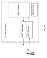
- Figure 15 shows a block diagram depicting the user equipment 10, according to embodiments herein, for performing channel estimation of one or more long term channel properties at the user equipment 10.
- the user equipment 10 is configured to be served by a radio network node 12.
- the user equipment 10 comprises a processor 1501 configured to assume that a default CSI-RS resource is co-located with a DMRS port when co-location is not explicitly signalled from the radio network node 12.
- the default CSI-RS resource is configured by reading a predetermined entry in a configurable list of candidate co-location CSI-RS resources for a dynamic indication of co-location options in a DCI format.
- the processor 1501 is further configured to, when assumed to be co-located, estimate one or more long term channel properties of the DMRS port and the default CSI-RS resource based on the assumption that the default CSI-RS resource is co-located with the DMRS port.
- the processor 1501 may further be configured to estimate one or more long term channel properties of the DMRS port and the default CSI-RS resource by performing joint or partly joint channel estimation on signals from the DMRS port and the CSI-RS resource.
- the DCI format is e.g. the DCI format 2D.
- the DMRS port is an ePDCCH DMRS port or a PDSCH DMRS port.
- the wording "not explicitly signaled" means e.g. that a received scheduling assignment for the user equipment 10, such as a DCI message, does not include a quasi-co-location field.
- the long term channel properties may comprise a group with respect of one or more long term reference signal properties comprising: received power, average channel gain, delay spread, frequency shift, Doppler spread, and propagation delay.
- the user equipment 10 further comprises a receiver 1502 that may be configured to receive a co-location information from the radio network node 12.
- the co-location information comprises an indication of a behaviour, which behaviour is related to a co-location assumption.
- the indication is a composite behaviour indicating an ePDCCH behaviour and a PDSCH behaviour.
- a configuration of the ePDCCH behaviour and/or the PDSCH behaviour may be a function of a selected transmission mode, wherein a set of parameters configured for each behaviour is limited to parameters relevant for the selected transmission mode.
- the user equipment 10 comprises a transmitter (TX) 1503 configured to transmit signals, feedback or similar to the radio network node.
- TX transmitter
- the user equipment 10 further comprises a memory 1504 that may be configured to store co-location information, default CSI-RS and similar applications that when executed performs methods herein,.
- the method actions in the radio network node exemplified to as the radio base station 12 in the figures, for transmitting reference signals according to some embodiments will now be described with reference to a flowchart depicted in Fig. 16 .
- the actions do not have to be taken in the order stated below, but may be taken in any suitable order. Actions performed in some embodiments are marked with dashed boxes.
- the user equipment 10 is served by the radio network node.
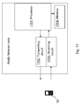
- Fig. 17 is a block diagram depicting the radio network node such as the radio base station 12, according to embodiments herein, for transmitting reference signals.
- the radio network node is configured to serve the user equipment 10.
- the radio network node comprises a processor 1701 configured to determine that the user equipment 10 assumes that a default CSI-RS resource is co-located with a DMRS port when co-location is not explicitly signalled to the user equipment 10.
- the default CSI-RS resource is configured by reading a predetermined entry in a configurable list of candidate co-location CSI-RS resources for a dynamic indication of co-location options in a DCI format.
- the DCI format may be the DCI format 2D.
- the DMRS port may be an ePDCCH DMRS port or a PDSCH DMRS port.
- the radio network node further comprises a transmitting circuit 1702 configured to transmit a CSI-RS resource and a DMRS port in a co-located manner based on the determined assumption.
- the transmitting circuit 1702 may further be configured to transmit a co-location information to the user equipment 10, which co-location information comprises an indication of a behaviour, which behaviour is related to a co-location assumption.
- the indication may be a composite behaviour indicating an ePDCCH behaviour and a PDSCH behaviour.
- a configuration of an ePDCCH behaviour and/or a PDSCH behaviour may be a function of a selected transmission mode, wherein a set of parameters configured for each behaviour is limited to parameters relevant for the selected transmission mode.
- the radio network node comprises a receiving circuit 1703 configured to receive signals, feedback or similar from the user equipment 10.
- the radio network node further comprises a memory 1704 that may be configured to store co-location information, default CSI-RS, applications that when executed performs methods herein, and similar.
- wireless terminals also referred to as user equipment, or "UEs”. More particularly, specific embodiments are described in the context of systems using LTE technology, as standardized by the membership of the 3GPP. It will be understood, however, that the present invention is not limited to such embodiments and may be embodied generally in various types of communication networks.
- the terms mobile terminal, wireless terminal, or UE can refer to any device that receives data from a communication network, and may include, but are not limited to, a mobile telephone, "cellular" telephone, laptop/portable computer, pocket computer, hand-held computer, and/or desktop computer.
- base station which may be referred to in various contexts as NodeB, for example, and "wireless terminal,” “mobile terminal,” or “wireless device”, above often referred to as “UE” or “User Equipment” should be considering non-limiting and does not necessarily imply a certain hierarchical relation between two particular nodes of a communication link.
- a base station e.g., a "NodeB”
- a wireless terminal e.g., a "UE”
- UE User Equipment
- the functional blocks for performing the disclosed function, as well as one or more functions from other receiver circuits may be implemented using digital logic and/or one or more microcontrollers, microprocessors, or other digital hardware. In some embodiments, several or all of the various functions may be implemented together, such as in a single application-specific integrated circuit (ASIC), or in two or more separate devices with appropriate hardware and/or software interfaces between them. Several functions may be implemented on a processor shared with other functional components of a wireless terminal, for example.
- ASIC application-specific integrated circuit
- processors or “controller” as used herein does not exclusively refer to hardware capable of executing software and may implicitly include, without limitation, digital signal processor (DSP) hardware, read-only memory (ROM) for storing software, random-access memory for storing software and/or program or application data, and non-volatile memory.
- DSP digital signal processor
- ROM read-only memory
- RAM random-access memory
- non-volatile memory non-volatile memory
Landscapes
- Engineering & Computer Science (AREA)
- Signal Processing (AREA)
- Computer Networks & Wireless Communication (AREA)
- Power Engineering (AREA)
- Mobile Radio Communication Systems (AREA)
Claims (16)
- Verfahren in einer Benutzervorrichtung (10) zum Durchführen einer Kanalabschätzung von einem oder mehreren langfristigen Kanaleigenschaften an der Benutzervorrichtung (10), wobei die Benutzervorrichtung (10) durch einen Funknetzwerkknoten (12) bedient wird; wobei das Verfahren umfasst:- Annehmen (1401), dass eine Standardkanalzustandsinformation-Referenzsignal-Ressource, Standard-CSI-RS-Ressource, einen gemeinsamen Standort mit einem Demodulationsreferenzsignal-Port, DMRS-Port, hat, wenn ein gemeinsamer Standort nicht explizit vom Funknetzwerkknoten (12) signalisiert wird, wobei "nicht explizit signalisiert" bedeutet, dass eine empfangene Zeitplanzuweisung kein quasi-gemeinsames Standortfeld beinhaltet; und- wenn ein gemeinsamer Standort angenommen wird, Abschätzen (1403) einer oder mehrerer langfristiger Kanaleigenschaften des DMRS-Ports und der Standard-CSI-RS-Ressource basierend auf der Annahme, dass die Standard-CSI-RS-Ressource einen gemeinsamen Standort mit dem DMRS-Port hat;dadurch gekennzeichnet, dass die Standard-CSI-RS-Ressource konfiguriert wird durch Lesen eines vorbestimmten Eintrags in einer konfigurierbaren Liste von Kandidaten von CSI-RS-Ressourcen mit einem gemeinsamen Standort auf einen dynamischen Hinweis auf Optionen für einen gemeinsamen Standort in einem Downlink-Steuerinformationsformat, DCI-Format.
- Verfahren nach Anspruch 1, wobei das Durchführen des Abschätzens (1403) durch die gemeinsame oder teilweise gemeinsame Kanalabschätzung an Signalen aus dem DMRS-Port und der CSI-RS-Ressource durchgeführt wird.
- Verfahren nach einem der Ansprüche 1-2, wobei die langfristigen Kanaleigenschaften eine Gruppe umfassen mit Bezug auf eine oder mehrere langfristige Referenzsignaleigenschaften beinhaltend: Empfangsleistung, mittlere Kanalverstärkung, Verzögerungsverbreiterung, Frequenzverschiebung, Dopplerverbreiterung und Ausbreitungsverzögerung.
- Verfahren nach einem der Ansprüche 1-3, ferner umfassend:- Empfangen (1402) einer Information bezüglich eines gemeinsamen Standorts vom Funknetzwerkknoten (12), wobei die Information bezüglich eines gemeinsamen Standorts einen Hinweis auf ein Verhalten beinhaltet, wobei das Verhalten mit einer Annahme eines gemeinsamen Standorts zusammenhängt.
- Verfahren nach Anspruch 4, wobei der Hinweis ein zusammengesetztes Verhalten ist, das ein Verhalten eines verbesserten physikalischen Downlink-Steuerkanals, ePDCCH, und ein Verhalten eines physikalischen Downlink-Gemeinschaftskanals, PDSCH, anzeigt.
- Verfahren nach Anspruch 5, wobei eine Konfiguration des ePDCCH-Verhaltens und/oder des PDSCH-Verhaltens eine Funktion eines ausgewählten Sendemodus ist, wobei ein Satz von Parametern, der für jedes Verhalten konfiguriert ist, auf Parameter beschränkt ist, die relevant für den ausgewählten Sendemodus sind.
- Verfahren in einem Funknetzwerkknoten (12,13) zum Senden von Referenzsignalen, wobei eine Benutzervorrichtung (10) von dem Funknetzwerkknoten (12) bedient wird; wobei das Verfahren umfasst:- Feststellen (1601), dass die Benutzervorrichtung (10) annimmt, dass eine Standardkanalzustandsinformation-Referenzsignal-Ressource, Standard-CSI-RS-Ressource, einen gemeinsamen Standort mit einem Demodulationsreferenzsignal-Port, DMRS-Port, hat, wenn der Benutzervorrichtung (10) ein gemeinsamer Standort nicht explizit signalisiert wird, wobei "nicht explizit signalisiert" bedeutet, dass eine gesendete Zeitplanzuweisung kein quasi-gemeinsames Standortfeld beinhaltet; und- Senden (1602) einer CSI-RS-Ressource und eines DMRS-Ports in einer Weise bezüglich eines gemeinsamen Standorts basierend auf der festgestellten Annahme;dadurch gekennzeichnet, dass die Standard-CSI-RS-Ressource konfiguriert wird durch Lesen eines vorbestimmten Eintrags in einer konfigurierbaren Liste von Kandidaten von CSI-RS-Ressourcen mit einem gemeinsamen Standort auf einen dynamischen Hinweis auf Optionen für einen gemeinsamen Standort in einem Downlink-Steuerinformationsformat, DCI-Format.
- Verfahren nach Anspruch 7, ferner umfassend:- Signalisieren (1603) einer Information bezüglich eines gemeinsamen Standorts an die Benutzervorrichtung (10), wobei die Information bezüglich eines gemeinsamen Standorts einen Hinweis auf ein Verhalten beinhaltet, wobei das Verhalten mit einer Annahme eines gemeinsamen Standorts zusammenhängt.
- Verfahren nach Anspruch 8, wobei eine Konfiguration eines Verhaltens eines verbesserten physikalischen Downlink-Steuerkanals, ePDCCH, und/oder eines Verhaltens eines physikalischen Downlink-Gemeinschaftskanals, PDSCH, eine Funktion eines ausgewählten Sendemodus ist, wobei ein Satz von Parametern, der für jedes Verhalten konfiguriert ist, auf Parameter beschränkt ist, die relevant für den ausgewählten Sendemodus sind.
- Benutzervorrichtung (10) zum Ausführen einer Kanalabschätzung von einer oder mehreren langfristigen Kanaleigenschaften an der Benutzervorrichtung (10), wobei die Benutzervorrichtung (10) konfiguriert ist, um durch einen Funknetzwerkknoten (12) bedient zu werden; wobei die Benutzervorrichtung (10) umfasst:ein Prozessor (1501), der konfiguriert ist, um anzunehmen, dass eine Standardkanalzustandsinformation-Referenzsignal-Ressource, Standard-CSI-RS-Ressource, einen gemeinsamen Standort mit einem Demodulationsreferenzsignal-Port, DMRS-Port, hat, wenn ein gemeinsamer Standort nicht explizit vom Funknetzwerkknoten (12) signalisiert ist, wobei "nicht explizit signalisiert" bedeutet, dass eine gesendete Zeitplanzuweisung kein quasi-gemeinsames Standortfeld beinhaltet; und, wenn ein gemeinsamer Standort angenommen wird, der Prozessor ferner konfiguriert ist, um eine oder mehrere langfristige Kanaleigenschaften des DMRS-Ports und der Standard-CSI-RS-Ressource basierend auf der Annahme, dass die Standard-CSI-RS-Ressource einen gemeinsamen Standort mit dem DMRS-Port hat, abzuschätzen;dadurch gekennzeichnet, dass die Standard-CSI-RS-Ressource konfiguriert ist durch Lesen eines vorbestimmten Eintrags in einer konfigurierbaren Liste von Kandidaten von CSI-RS-Ressourcen mit einem gemeinsamen Standort auf einen dynamischen Hinweis auf Optionen für einen gemeinsamen Standort in einem Downlink-Steuerinformationsformat, DCI-Format.
- Benutzervorrichtung (10) nach Anspruch 10, wobei der Prozessor (1501) ferner konfiguriert ist, um eine oder mehrere langfristige Kanaleigenschaften des DMRS-Ports und der Standard-CSI-RS-Ressource mittels einer Durchführung einer gemeinsamen oder teilweise gemeinsamen Kanalabschätzung an Signalen aus dem DMRS-Port und der CSI-RS-Ressource abzuschätzen.
- Benutzervorrichtung (10) nach einem der Ansprüche 10-11, wobei die langfristigen Kanaleigenschaften eine Gruppe umfassen mit Bezug auf eine oder mehrere langfristige Referenzsignaleigenschaften beinhaltend: Empfangsleistung, mittlere Kanalverstärkung, Verzögerungsverbreiterung, Frequenzverschiebung, Dopplerverbreiterung und Ausbreitungsverzögerung.
- Benutzervorrichtung (10) nach einem der Ansprüche 10-12, ferner umfassend: einen Empfänger (1502), der konfiguriert ist, um eine Information bezüglich eines gemeinsamen Standorts vom Funknetzwerkknoten (12) zu empfangen, wobei die Information bezüglich eines gemeinsamen Standorts einen Hinweis auf ein Verhalten beinhaltet, wobei das Verhalten mit einer Annahme eines gemeinsamen Standorts zusammenhängt.
- Funknetzwerkknoten (12, 13) zum Senden von Referenzsignalen, wobei der Funknetzwerkknoten (12) konfiguriert ist, um eine Benutzervorrichtung (10) zu bedienen; wobei der Funknetzwerkknoten umfasst:einen Prozessor (1701), der konfiguriert ist, um festzustellen, dass die Benutzervorrichtung (10) annimmt, dass eine Standardkanalzustandsinformation-Referenzsignal-Ressource, Standard-CSI-RS-Ressource, einen gemeinsamen Standort mit einem Demodulationsreferenzsignal-Port, DMRS-Port, hat, wenn der Benutzervorrichtung (10) ein gemeinsamer Standort nicht explizit signalisiert ist, wobei "nicht explizit signalisiert" bedeutet, dass eine gesendete Zeitplanzuweisung kein quasi-gemeinsames Standortfeld beinhaltet; und eine Sendeschaltung (1702), die konfiguriert ist, um eine CSI-RS-Ressource und einen DMRS-Port in einer Weise bezüglich eines gemeinsamen Standorts basierend auf der festgestellten Annahme zu senden;dadurch gekennzeichnet, dass die Standard-CSI-RS-Ressource konfiguriert ist durch Lesen eines vorbestimmten Eintrags in einer konfigurierbaren Liste von Kandidaten von CSI-RS-Ressourcen mit einem gemeinsamen Standort auf einen dynamischen Hinweis auf Optionen für einen gemeinsamen Standort in einem Downlink-Steuerinformationsformat, DCI-Format.
- Funknetzwerkknoten (12, 13) nach Anspruch 14, wobei die Sendeschaltung (1702) ferner konfiguriert ist, um eine Information bezüglich eines gemeinsamen Standorts der Benutzervorrichtung (10) zu signalisieren, wobei die Information bezüglich eines gemeinsamen Standorts einen Hinweis auf ein Verhalten beinhaltet, wobei das Verhalten mit einer Annahme eines gemeinsamen Standorts zusammenhängt.
- Funknetzwerkknoten (12, 13) nach Anspruch 15, wobei der Hinweis ein zusammengesetztes Verhalten ist, das ein Verhalten eines verbesserten physikalischen Downlink-Steuerkanals, ePDCCH, und ein Verhalten eines physikalischen Downlink-Gemeinschaftskanals, PDSCH, anzeigt.
Priority Applications (1)
| Application Number | Priority Date | Filing Date | Title |
|---|---|---|---|
| EP16197649.3A EP3145109B1 (de) | 2012-09-28 | 2013-09-19 | Colokationsanzeige für csi-rs und dmrs |
Applications Claiming Priority (3)
| Application Number | Priority Date | Filing Date | Title |
|---|---|---|---|
| US201261707811P | 2012-09-28 | 2012-09-28 | |
| US13/907,529 US9769807B2 (en) | 2012-09-28 | 2013-05-31 | User equipment, radio network node and methods therein |
| PCT/IB2013/058652 WO2014049496A1 (en) | 2012-09-28 | 2013-09-19 | Csi-rs and dmrs co-location indication |
Related Child Applications (1)
| Application Number | Title | Priority Date | Filing Date |
|---|---|---|---|
| EP16197649.3A Division EP3145109B1 (de) | 2012-09-28 | 2013-09-19 | Colokationsanzeige für csi-rs und dmrs |
Publications (2)
| Publication Number | Publication Date |
|---|---|
| EP2901607A1 EP2901607A1 (de) | 2015-08-05 |
| EP2901607B1 true EP2901607B1 (de) | 2016-11-09 |
Family
ID=50385114
Family Applications (2)
| Application Number | Title | Priority Date | Filing Date |
|---|---|---|---|
| EP16197649.3A Active EP3145109B1 (de) | 2012-09-28 | 2013-09-19 | Colokationsanzeige für csi-rs und dmrs |
| EP13803230.5A Active EP2901607B1 (de) | 2012-09-28 | 2013-09-19 | Colokationsanzeige für csi-rs und dmrs |
Family Applications Before (1)
| Application Number | Title | Priority Date | Filing Date |
|---|---|---|---|
| EP16197649.3A Active EP3145109B1 (de) | 2012-09-28 | 2013-09-19 | Colokationsanzeige für csi-rs und dmrs |
Country Status (7)
| Country | Link |
|---|---|
| US (1) | US9769807B2 (de) |
| EP (2) | EP3145109B1 (de) |
| JP (1) | JP5973673B2 (de) |
| DK (1) | DK2901607T3 (de) |
| ES (1) | ES2614785T3 (de) |
| IN (1) | IN2015DN01617A (de) |
| WO (1) | WO2014049496A1 (de) |
Cited By (2)
| Publication number | Priority date | Publication date | Assignee | Title |
|---|---|---|---|---|
| CN109391569A (zh) * | 2017-08-02 | 2019-02-26 | 苹果公司 | 针对窄带系统的功率优化的自适应信道估计 |
| WO2019221388A1 (ko) * | 2018-05-14 | 2019-11-21 | 삼성전자 주식회사 | 무선 통신 시스템에서 채널 추정 방법 및 장치 |
Families Citing this family (71)
| Publication number | Priority date | Publication date | Assignee | Title |
|---|---|---|---|---|
| US8948293B2 (en) * | 2011-04-20 | 2015-02-03 | Texas Instruments Incorporated | Downlink multiple input multiple output enhancements for single-cell with remote radio heads |
| KR101557253B1 (ko) | 2011-10-07 | 2015-10-02 | 블랙베리 리미티드 | 무선 네트워크에서의 간섭 관리 |
| CN104247291B (zh) * | 2012-04-19 | 2019-09-24 | 三星电子株式会社 | 用于协作多点通信系统的参考符号端口的准同位识别的方法和装置 |
| US9621316B2 (en) | 2012-07-03 | 2017-04-11 | Lg Electronics Inc. | Method and device for receiving downlink signal in wireless communication system |
| US9839009B2 (en) | 2012-08-03 | 2017-12-05 | Qualcomm Incorporated | Methods and apparatus for processing control and/or shared channels in long term evolution (LTE) |
| KR102186240B1 (ko) | 2012-08-31 | 2020-12-03 | 엘지전자 주식회사 | 무선 통신 시스템에서 하향링크 신호 수신 방법 및 장치 |
| KR101846173B1 (ko) | 2012-09-16 | 2018-04-06 | 엘지전자 주식회사 | 협력적 송신을 지원하는 무선 통신 시스템에서 채널 상태 정보 송수신 방법 및 장치 |
| IN2015KN00417A (de) | 2012-10-04 | 2015-07-17 | Lg Electronics Inc | |
| WO2014065525A1 (ko) * | 2012-10-25 | 2014-05-01 | 엘지전자 주식회사 | 무선 통신 시스템에서 하향링크 신호 송수신 방법 및 이를 위한 장치 |
| US11139862B2 (en) * | 2012-11-02 | 2021-10-05 | Samsung Electronics Co., Ltd. | Configuration of rate matching and interference measurement resources for coordinated multi-point transmission |
| WO2014107136A1 (en) * | 2013-01-04 | 2014-07-10 | Telefonaktiebolaget L M Ericsson (Publ) | Method for estimating frequency offset using quasi-co-located reference signals |
| US9768898B2 (en) * | 2013-01-18 | 2017-09-19 | Lg Electronics Inc. | Method for reception in cooperative transmission environment and terminal |
| US9369253B2 (en) * | 2013-02-21 | 2016-06-14 | Blackberry Limited | Methods of interference measurement for advanced receiver in LTE/LTE-A |
| US9425946B2 (en) | 2013-02-21 | 2016-08-23 | Blackberry Limited | Interference measurement methods for advanced receiver in LTE/LTE-A |
| US8989755B2 (en) | 2013-02-26 | 2015-03-24 | Blackberry Limited | Methods of inter-cell resource sharing |
| CN105580455B (zh) * | 2013-09-27 | 2020-03-06 | 瑞典爱立信有限公司 | 用于估计大尺度信道特性的接收机和方法 |
| CN106416377B (zh) * | 2014-05-09 | 2020-02-28 | 瑞典爱立信有限公司 | 无线电通信网络中的发现信号设计 |
| CN105099642B (zh) * | 2014-05-19 | 2019-06-07 | 中兴通讯股份有限公司 | 一种数据传输方法、装置及计算机存储介质 |
| US10034271B2 (en) | 2014-06-13 | 2018-07-24 | Apple Inc. | Decoding of PCFICH in LTE for power savings and range improvement |
| CN105450561B (zh) * | 2014-09-28 | 2018-12-14 | 联想(北京)有限公司 | 一种信息处理方法及电子设备 |
| US10498513B2 (en) * | 2015-12-31 | 2019-12-03 | Idac Holdings, Inc. | Methods for dynamic management of reference signals |
| CN106961689B (zh) * | 2016-01-11 | 2019-04-30 | 北京展讯高科通信技术有限公司 | 参考信号的接收方法及装置 |
| CN108476121B (zh) * | 2016-02-03 | 2021-06-29 | 苹果公司 | 用于具有短传输时间间隔的物理下行共享信道传输的装置 |
| CN105516931A (zh) * | 2016-02-29 | 2016-04-20 | 重庆邮电大学 | 基于双频wlan接入点的室内差分定位方法 |
| CN109075825B (zh) * | 2016-05-04 | 2022-07-19 | 苹果公司 | 利用csi(信道状态信息)-rs(参考信号)ic(干扰消除)接收机的csi-rs传输 |
| CN113746521A (zh) * | 2016-05-10 | 2021-12-03 | 诺基亚技术有限公司 | 天线共置和接收器假设 |
| MX2018013518A (es) | 2016-05-12 | 2019-03-14 | Guangdong Oppo Mobile Telecommunications Corp Ltd | Metodo de transmision de se?al, dispositivo de red y dispositivo terminal. |
| US20190158206A1 (en) * | 2016-05-13 | 2019-05-23 | Intel IP Corporation | Multi-user multiple input multiple ouput systems |
| US10637624B2 (en) | 2016-08-11 | 2020-04-28 | Lg Electronics Inc. | Method for indicating QCL information for aperiodic CSI-RS in wireless communication system and apparatus for same |
| WO2018031870A1 (en) * | 2016-08-11 | 2018-02-15 | Donomo Innovations, Inc. | Method of selecting reception resource and method of csi-rs transmission |
| WO2018030947A1 (en) * | 2016-08-12 | 2018-02-15 | Telefonaktiebolaget Lm Ericsson (Publ) | Reducing overhead in sidelink transmissions |
| CN109565714A (zh) * | 2016-08-12 | 2019-04-02 | 华为技术有限公司 | 发送参考信号的方法和装置及接收参考信号的方法和装置 |
| US10039076B2 (en) | 2016-08-22 | 2018-07-31 | Qualcomm Incorporated | Declaring quasi co-location among multiple antenna ports |
| CN108377523A (zh) * | 2016-11-03 | 2018-08-07 | 上海掌门科技有限公司 | 一种用于实现无线接入点连接的方法与设备 |
| CN108023704B (zh) * | 2016-11-04 | 2021-10-26 | 华为技术有限公司 | 一种传输参考信号的方法、网络侧设备和用户设备 |
| WO2018083244A1 (en) * | 2016-11-04 | 2018-05-11 | Telefonaktiebolaget Lm Ericsson (Publ) | Transmission of control information using more than one beam pair link |
| WO2018127780A1 (en) | 2017-01-09 | 2018-07-12 | Telefonaktiebolaget Lm Ericsson (Publ) | Controllable beam management accuracy |
| CN108347324B (zh) * | 2017-01-25 | 2022-05-31 | 华为技术有限公司 | 通信方法和网络设备 |
| CN108365933B (zh) * | 2017-01-26 | 2023-07-18 | 华为技术有限公司 | 一种发送参考信号的方法及装置 |
| WO2018141425A1 (en) * | 2017-02-06 | 2018-08-09 | Telefonaktiebolaget Lm Ericsson (Publ) | Systems and methods of reducing interference in a wireless communications system |
| CN110291744B (zh) * | 2017-02-16 | 2022-05-24 | 高通股份有限公司 | 确定在平滑预编码下的dmrs平均延迟和延迟扩展的方法 |
| KR20190118643A (ko) * | 2017-03-24 | 2019-10-18 | 텔레폰악티에볼라겟엘엠에릭슨(펍) | 무선 디바이스를 위한 전송기 및 수신기 구성을 결정하는 시스템 및 방법 |
| US20200162134A1 (en) * | 2017-05-04 | 2020-05-21 | Ntt Docomo, Inc. | User equipment and method of channel state information (csi) acquisition |
| PL3619872T3 (pl) * | 2017-05-05 | 2024-03-04 | Apple Inc. | Sygnalizacja konfiguracji mapowania sygnału referencyjnego informacji o stanie kanału (CSI-RS) dla systemu New Radio (NR) |
| WO2018223349A1 (en) * | 2017-06-08 | 2018-12-13 | Qualcomm Incorporated | Collision handling mechanisms for dynamic tdd systems |
| WO2018227558A1 (en) * | 2017-06-16 | 2018-12-20 | Qualcomm Incorporated | Signaling design for multiple aperiodic csi feedback |
| CN109150467B (zh) | 2017-06-16 | 2022-10-11 | 华为技术有限公司 | 通信方法、相关设备及计算机存储介质 |
| WO2019018971A1 (en) * | 2017-07-24 | 2019-01-31 | Nec Corporation | METHODS AND DEVICES FOR DATA TRANSMISSION |
| GB2565332B (en) | 2017-08-10 | 2021-04-28 | Samsung Electronics Co Ltd | Network control |
| CN109391411B (zh) * | 2017-08-10 | 2021-03-02 | 电信科学技术研究院 | 一种导频配置方法、信道测量方法及通信设备 |
| US10790956B2 (en) * | 2017-08-11 | 2020-09-29 | Futurewei Technologies, Inc. | System and method for communicating time and frequency tracking signals using configurations for one port CSI-RSs |
| US11323892B2 (en) * | 2017-09-29 | 2022-05-03 | Lg Electronics Inc. | Method for transmitting and receiving data on basis of QCL in wireless communication system, and device therefor |
| US10707923B2 (en) * | 2017-10-13 | 2020-07-07 | Qualcomm Incorporated | Dynamic transmission configuration indication state updating |
| CN112020842B (zh) * | 2018-02-28 | 2023-10-03 | 瑞典爱立信有限公司 | 用于指示针对rrc连接之前的物理下行链路共享信道的时域资源分配的方法 |
| US11477809B2 (en) * | 2018-04-12 | 2022-10-18 | Qualcomm Incorporated | Techniques for channel estimation |
| CN110461043B (zh) * | 2018-05-08 | 2020-12-04 | 大唐移动通信设备有限公司 | 一种通道选择方法、基带单元及基站 |
| CN110475329B (zh) * | 2018-05-11 | 2020-11-06 | 维沃移动通信有限公司 | 无线通信方法、装置及网络设备 |
| US10673588B2 (en) | 2018-05-14 | 2020-06-02 | At&T Intellectual Property I, L.P. | Shared demodulation reference signal design for control channels in 5G or other next generation networks |
| US11445487B2 (en) | 2018-06-15 | 2022-09-13 | At&T Intellectual Property I, L.P. | Single user super position transmission for future generation wireless communication systems |
| US11140668B2 (en) | 2018-06-22 | 2021-10-05 | At&T Intellectual Property I, L.P. | Performance of 5G MIMO |
| AU2018431078B2 (en) * | 2018-07-04 | 2024-05-09 | Ntt Docomo, Inc. | User terminal |
| WO2020030254A1 (en) * | 2018-08-07 | 2020-02-13 | Huawei Technologies Co., Ltd. | Joint channel estimation |
| US11240841B2 (en) * | 2018-08-10 | 2022-02-01 | Qualcomm Incorporated | Default communication configuration for communication across carriers |
| US20220116247A1 (en) * | 2018-09-28 | 2022-04-14 | Apple Inc. | Demodulation Reference Signal Transmission from Multiple Base Stations |
| US11563537B2 (en) * | 2018-10-16 | 2023-01-24 | Qualcomm Incorporated | Exchanging quasi colocation information between a user equipment and a base station that indicates an association between a spatial parameter and a current transmission configuration |
| US10945281B2 (en) | 2019-02-15 | 2021-03-09 | At&T Intellectual Property I, L.P. | Facilitating improved performance of multiple downlink control channels in advanced networks |
| WO2020205589A1 (en) * | 2019-03-29 | 2020-10-08 | Apple Inc. | Calculation of a reference signal received power of a resynchronisation signal in lte |
| CN112398625B (zh) * | 2019-08-16 | 2022-04-12 | 华为技术有限公司 | 一种通信方法及装置 |
| WO2021108653A1 (en) * | 2019-11-28 | 2021-06-03 | Qualcomm Incorporated | Using demodulation reference signal of a data transmission as a quasi-colocation reference signal source for another data transmission |
| US20240163135A1 (en) * | 2021-04-02 | 2024-05-16 | Beijing Xiaomi Mobile Software Co., Ltd. | Configuration method and apparatus for joint channel estimation, and device and storage medium |
| US11997185B2 (en) * | 2021-06-23 | 2024-05-28 | Qualcomm Incorporated | Demodulator configuration based on user equipment signaling |
Family Cites Families (6)
| Publication number | Priority date | Publication date | Assignee | Title |
|---|---|---|---|---|
| US8270359B2 (en) * | 2010-03-15 | 2012-09-18 | Motorola Mobility Llc | Antenna port information signaling in wireless communication system |
| US8780766B2 (en) * | 2010-08-16 | 2014-07-15 | Qualcomm Incorporated | Interleaving for relay physical downlink control channel (R-PDCCH) |
| JP2012147048A (ja) * | 2011-01-06 | 2012-08-02 | Ntt Docomo Inc | 無線基地局装置、移動端末装置、及び無線通信方法 |
| GB2500382B (en) * | 2012-03-19 | 2014-11-26 | Broadcom Corp | Methods, apparatus and computer programs for configuring user equipment |
| CN104247291B (zh) * | 2012-04-19 | 2019-09-24 | 三星电子株式会社 | 用于协作多点通信系统的参考符号端口的准同位识别的方法和装置 |
| PL2903174T3 (pl) * | 2012-09-27 | 2020-06-01 | Electronics And Telecommunications Research Institute | Sposób sygnalizowania informacji kontrolnej dla koordynowanej transmisji wielopunktowej w bezprzewodowym systemie komunikacyjnym |
-
2013
- 2013-05-31 US US13/907,529 patent/US9769807B2/en active Active
- 2013-09-19 WO PCT/IB2013/058652 patent/WO2014049496A1/en active Application Filing
- 2013-09-19 DK DK13803230.5T patent/DK2901607T3/en active
- 2013-09-19 IN IN1617DEN2015 patent/IN2015DN01617A/en unknown
- 2013-09-19 JP JP2015533731A patent/JP5973673B2/ja active Active
- 2013-09-19 EP EP16197649.3A patent/EP3145109B1/de active Active
- 2013-09-19 ES ES13803230.5T patent/ES2614785T3/es active Active
- 2013-09-19 EP EP13803230.5A patent/EP2901607B1/de active Active
Cited By (4)
| Publication number | Priority date | Publication date | Assignee | Title |
|---|---|---|---|---|
| CN109391569A (zh) * | 2017-08-02 | 2019-02-26 | 苹果公司 | 针对窄带系统的功率优化的自适应信道估计 |
| CN109391569B (zh) * | 2017-08-02 | 2021-11-16 | 苹果公司 | 针对窄带系统的功率优化的自适应信道估计的方法和设备 |
| WO2019221388A1 (ko) * | 2018-05-14 | 2019-11-21 | 삼성전자 주식회사 | 무선 통신 시스템에서 채널 추정 방법 및 장치 |
| US11477053B2 (en) | 2018-05-14 | 2022-10-18 | Samsung Electronics Co., Ltd. | Method and apparatus for estimating channel in wireless communication system |
Also Published As
| Publication number | Publication date |
|---|---|
| JP5973673B2 (ja) | 2016-08-23 |
| US20140092827A1 (en) | 2014-04-03 |
| WO2014049496A1 (en) | 2014-04-03 |
| IN2015DN01617A (de) | 2015-07-03 |
| ES2614785T3 (es) | 2017-06-01 |
| EP2901607A1 (de) | 2015-08-05 |
| EP3145109B1 (de) | 2019-11-20 |
| US9769807B2 (en) | 2017-09-19 |
| JP2016500213A (ja) | 2016-01-07 |
| DK2901607T3 (en) | 2017-02-13 |
| EP3145109A1 (de) | 2017-03-22 |
Similar Documents
| Publication | Publication Date | Title |
|---|---|---|
| EP2901607B1 (de) | Colokationsanzeige für csi-rs und dmrs | |
| US11637721B2 (en) | Methods and arrangements for channel estimation | |
| US11838158B2 (en) | Method and apparatus for configuring demodulation reference signal position in wireless cellular communication system | |
| JP6076044B2 (ja) | 無線通信方法、無線通信システム、無線基地局及びユーザ端末 | |
| JP6078078B2 (ja) | 無線・ネットワークにおける基準信号生成の初期設定 | |
| KR101777424B1 (ko) | 다중 노드 시스템에서 신호 수신 방법 및 장치 | |
| JP6095991B2 (ja) | 無線基地局、ユーザ端末及び無線通信方法 | |
| JP5755800B2 (ja) | 信号送受信方法及びシステム並びに関連するシグナリング方法 | |
| WO2014073375A1 (ja) | 無線通信方法、無線通信システム、無線基地局及びユーザ端末 | |
| JP6212188B2 (ja) | 無線通信方法、無線基地局及びユーザ端末 | |
| JP2012080423A (ja) | 基地局装置、移動端末装置及び通信制御方法 | |
| US10110265B2 (en) | Enabling interference mitigation and cancellation receivers | |
| US20130286966A1 (en) | Method of allocating radio resources for control channel and method for receiving the control channel | |
| JP5814207B2 (ja) | 基地局装置及び移動端末装置 | |
| US20190074944A1 (en) | User terminal, radio base station and radio communication method | |
| WO2019049345A1 (ja) | ユーザ端末及び無線通信方法 | |
| JP2012138956A (ja) | 移動通信システム及び基地局装置 | |
| JP2014140237A (ja) | 移動通信システム及び基地局装置 |
Legal Events
| Date | Code | Title | Description |
|---|---|---|---|
| PUAI | Public reference made under article 153(3) epc to a published international application that has entered the european phase |
Free format text: ORIGINAL CODE: 0009012 |
|
| 17P | Request for examination filed |
Effective date: 20150303 |
|
| AK | Designated contracting states |
Kind code of ref document: A1 Designated state(s): AL AT BE BG CH CY CZ DE DK EE ES FI FR GB GR HR HU IE IS IT LI LT LU LV MC MK MT NL NO PL PT RO RS SE SI SK SM TR |
|
| AX | Request for extension of the european patent |
Extension state: BA ME |
|
| DAX | Request for extension of the european patent (deleted) | ||
| GRAP | Despatch of communication of intention to grant a patent |
Free format text: ORIGINAL CODE: EPIDOSNIGR1 |
|
| INTG | Intention to grant announced |
Effective date: 20160511 |
|
| GRAS | Grant fee paid |
Free format text: ORIGINAL CODE: EPIDOSNIGR3 |
|
| GRAA | (expected) grant |
Free format text: ORIGINAL CODE: 0009210 |
|
| AK | Designated contracting states |
Kind code of ref document: B1 Designated state(s): AL AT BE BG CH CY CZ DE DK EE ES FI FR GB GR HR HU IE IS IT LI LT LU LV MC MK MT NL NO PL PT RO RS SE SI SK SM TR |
|
| REG | Reference to a national code |
Ref country code: GB Ref legal event code: FG4D |
|
| REG | Reference to a national code |
Ref country code: AT Ref legal event code: REF Ref document number: 844798 Country of ref document: AT Kind code of ref document: T Effective date: 20161115 Ref country code: CH Ref legal event code: EP |
|
| REG | Reference to a national code |
Ref country code: IE Ref legal event code: FG4D |
|
| REG | Reference to a national code |
Ref country code: DE Ref legal event code: R096 Ref document number: 602013013935 Country of ref document: DE |
|
| REG | Reference to a national code |
Ref country code: NL Ref legal event code: FP |
|
| REG | Reference to a national code |
Ref country code: DK Ref legal event code: T3 Effective date: 20170206 |
|
| PG25 | Lapsed in a contracting state [announced via postgrant information from national office to epo] |
Ref country code: LV Free format text: LAPSE BECAUSE OF FAILURE TO SUBMIT A TRANSLATION OF THE DESCRIPTION OR TO PAY THE FEE WITHIN THE PRESCRIBED TIME-LIMIT Effective date: 20161109 |
|
| REG | Reference to a national code |
Ref country code: LT Ref legal event code: MG4D |
|
| REG | Reference to a national code |
Ref country code: AT Ref legal event code: MK05 Ref document number: 844798 Country of ref document: AT Kind code of ref document: T Effective date: 20161109 |
|
| PG25 | Lapsed in a contracting state [announced via postgrant information from national office to epo] |
Ref country code: GR Free format text: LAPSE BECAUSE OF FAILURE TO SUBMIT A TRANSLATION OF THE DESCRIPTION OR TO PAY THE FEE WITHIN THE PRESCRIBED TIME-LIMIT Effective date: 20170210 Ref country code: LT Free format text: LAPSE BECAUSE OF FAILURE TO SUBMIT A TRANSLATION OF THE DESCRIPTION OR TO PAY THE FEE WITHIN THE PRESCRIBED TIME-LIMIT Effective date: 20161109 Ref country code: SE Free format text: LAPSE BECAUSE OF FAILURE TO SUBMIT A TRANSLATION OF THE DESCRIPTION OR TO PAY THE FEE WITHIN THE PRESCRIBED TIME-LIMIT Effective date: 20161109 Ref country code: NO Free format text: LAPSE BECAUSE OF FAILURE TO SUBMIT A TRANSLATION OF THE DESCRIPTION OR TO PAY THE FEE WITHIN THE PRESCRIBED TIME-LIMIT Effective date: 20170209 |
|
| PG25 | Lapsed in a contracting state [announced via postgrant information from national office to epo] |
Ref country code: PT Free format text: LAPSE BECAUSE OF FAILURE TO SUBMIT A TRANSLATION OF THE DESCRIPTION OR TO PAY THE FEE WITHIN THE PRESCRIBED TIME-LIMIT Effective date: 20170309 Ref country code: IS Free format text: LAPSE BECAUSE OF FAILURE TO SUBMIT A TRANSLATION OF THE DESCRIPTION OR TO PAY THE FEE WITHIN THE PRESCRIBED TIME-LIMIT Effective date: 20170309 Ref country code: PL Free format text: LAPSE BECAUSE OF FAILURE TO SUBMIT A TRANSLATION OF THE DESCRIPTION OR TO PAY THE FEE WITHIN THE PRESCRIBED TIME-LIMIT Effective date: 20161109 Ref country code: HR Free format text: LAPSE BECAUSE OF FAILURE TO SUBMIT A TRANSLATION OF THE DESCRIPTION OR TO PAY THE FEE WITHIN THE PRESCRIBED TIME-LIMIT Effective date: 20161109 Ref country code: RS Free format text: LAPSE BECAUSE OF FAILURE TO SUBMIT A TRANSLATION OF THE DESCRIPTION OR TO PAY THE FEE WITHIN THE PRESCRIBED TIME-LIMIT Effective date: 20161109 Ref country code: AT Free format text: LAPSE BECAUSE OF FAILURE TO SUBMIT A TRANSLATION OF THE DESCRIPTION OR TO PAY THE FEE WITHIN THE PRESCRIBED TIME-LIMIT Effective date: 20161109 Ref country code: FI Free format text: LAPSE BECAUSE OF FAILURE TO SUBMIT A TRANSLATION OF THE DESCRIPTION OR TO PAY THE FEE WITHIN THE PRESCRIBED TIME-LIMIT Effective date: 20161109 |
|
| REG | Reference to a national code |
Ref country code: ES Ref legal event code: FG2A Ref document number: 2614785 Country of ref document: ES Kind code of ref document: T3 Effective date: 20170601 |
|
| PG25 | Lapsed in a contracting state [announced via postgrant information from national office to epo] |
Ref country code: SK Free format text: LAPSE BECAUSE OF FAILURE TO SUBMIT A TRANSLATION OF THE DESCRIPTION OR TO PAY THE FEE WITHIN THE PRESCRIBED TIME-LIMIT Effective date: 20161109 Ref country code: RO Free format text: LAPSE BECAUSE OF FAILURE TO SUBMIT A TRANSLATION OF THE DESCRIPTION OR TO PAY THE FEE WITHIN THE PRESCRIBED TIME-LIMIT Effective date: 20161109 Ref country code: EE Free format text: LAPSE BECAUSE OF FAILURE TO SUBMIT A TRANSLATION OF THE DESCRIPTION OR TO PAY THE FEE WITHIN THE PRESCRIBED TIME-LIMIT Effective date: 20161109 |
|
| REG | Reference to a national code |
Ref country code: DE Ref legal event code: R097 Ref document number: 602013013935 Country of ref document: DE |
|
| PG25 | Lapsed in a contracting state [announced via postgrant information from national office to epo] |
Ref country code: SM Free format text: LAPSE BECAUSE OF FAILURE TO SUBMIT A TRANSLATION OF THE DESCRIPTION OR TO PAY THE FEE WITHIN THE PRESCRIBED TIME-LIMIT Effective date: 20161109 Ref country code: BE Free format text: LAPSE BECAUSE OF FAILURE TO SUBMIT A TRANSLATION OF THE DESCRIPTION OR TO PAY THE FEE WITHIN THE PRESCRIBED TIME-LIMIT Effective date: 20161109 Ref country code: BG Free format text: LAPSE BECAUSE OF FAILURE TO SUBMIT A TRANSLATION OF THE DESCRIPTION OR TO PAY THE FEE WITHIN THE PRESCRIBED TIME-LIMIT Effective date: 20170209 Ref country code: IT Free format text: LAPSE BECAUSE OF FAILURE TO SUBMIT A TRANSLATION OF THE DESCRIPTION OR TO PAY THE FEE WITHIN THE PRESCRIBED TIME-LIMIT Effective date: 20161109 |
|
| PLBE | No opposition filed within time limit |
Free format text: ORIGINAL CODE: 0009261 |
|
| STAA | Information on the status of an ep patent application or granted ep patent |
Free format text: STATUS: NO OPPOSITION FILED WITHIN TIME LIMIT |
|
| 26N | No opposition filed |
Effective date: 20170810 |
|
| PG25 | Lapsed in a contracting state [announced via postgrant information from national office to epo] |
Ref country code: SI Free format text: LAPSE BECAUSE OF FAILURE TO SUBMIT A TRANSLATION OF THE DESCRIPTION OR TO PAY THE FEE WITHIN THE PRESCRIBED TIME-LIMIT Effective date: 20161109 |
|
| REG | Reference to a national code |
Ref country code: CH Ref legal event code: PL |
|
| PG25 | Lapsed in a contracting state [announced via postgrant information from national office to epo] |
Ref country code: MC Free format text: LAPSE BECAUSE OF FAILURE TO SUBMIT A TRANSLATION OF THE DESCRIPTION OR TO PAY THE FEE WITHIN THE PRESCRIBED TIME-LIMIT Effective date: 20161109 |
|
| REG | Reference to a national code |
Ref country code: IE Ref legal event code: MM4A |
|
| PG25 | Lapsed in a contracting state [announced via postgrant information from national office to epo] |
Ref country code: LU Free format text: LAPSE BECAUSE OF NON-PAYMENT OF DUE FEES Effective date: 20170919 |
|
| REG | Reference to a national code |
Ref country code: FR Ref legal event code: ST Effective date: 20180531 |
|
| PG25 | Lapsed in a contracting state [announced via postgrant information from national office to epo] |
Ref country code: LI Free format text: LAPSE BECAUSE OF NON-PAYMENT OF DUE FEES Effective date: 20170930 Ref country code: IE Free format text: LAPSE BECAUSE OF NON-PAYMENT OF DUE FEES Effective date: 20170919 Ref country code: CH Free format text: LAPSE BECAUSE OF NON-PAYMENT OF DUE FEES Effective date: 20170930 |
|
| PG25 | Lapsed in a contracting state [announced via postgrant information from national office to epo] |
Ref country code: FR Free format text: LAPSE BECAUSE OF NON-PAYMENT OF DUE FEES Effective date: 20171002 |
|
| PG25 | Lapsed in a contracting state [announced via postgrant information from national office to epo] |
Ref country code: MT Free format text: LAPSE BECAUSE OF NON-PAYMENT OF DUE FEES Effective date: 20170919 |
|
| PG25 | Lapsed in a contracting state [announced via postgrant information from national office to epo] |
Ref country code: HU Free format text: LAPSE BECAUSE OF FAILURE TO SUBMIT A TRANSLATION OF THE DESCRIPTION OR TO PAY THE FEE WITHIN THE PRESCRIBED TIME-LIMIT; INVALID AB INITIO Effective date: 20130919 |
|
| PG25 | Lapsed in a contracting state [announced via postgrant information from national office to epo] |
Ref country code: CY Free format text: LAPSE BECAUSE OF FAILURE TO SUBMIT A TRANSLATION OF THE DESCRIPTION OR TO PAY THE FEE WITHIN THE PRESCRIBED TIME-LIMIT Effective date: 20161109 |
|
| PGFP | Annual fee paid to national office [announced via postgrant information from national office to epo] |
Ref country code: DK Payment date: 20190927 Year of fee payment: 7 Ref country code: CZ Payment date: 20190906 Year of fee payment: 7 |
|
| PG25 | Lapsed in a contracting state [announced via postgrant information from national office to epo] |
Ref country code: MK Free format text: LAPSE BECAUSE OF FAILURE TO SUBMIT A TRANSLATION OF THE DESCRIPTION OR TO PAY THE FEE WITHIN THE PRESCRIBED TIME-LIMIT Effective date: 20161109 |
|
| PGFP | Annual fee paid to national office [announced via postgrant information from national office to epo] |
Ref country code: ES Payment date: 20191001 Year of fee payment: 7 |
|
| PG25 | Lapsed in a contracting state [announced via postgrant information from national office to epo] |
Ref country code: TR Free format text: LAPSE BECAUSE OF FAILURE TO SUBMIT A TRANSLATION OF THE DESCRIPTION OR TO PAY THE FEE WITHIN THE PRESCRIBED TIME-LIMIT Effective date: 20161109 |
|
| PG25 | Lapsed in a contracting state [announced via postgrant information from national office to epo] |
Ref country code: AL Free format text: LAPSE BECAUSE OF FAILURE TO SUBMIT A TRANSLATION OF THE DESCRIPTION OR TO PAY THE FEE WITHIN THE PRESCRIBED TIME-LIMIT Effective date: 20161109 |
|
| REG | Reference to a national code |
Ref country code: DK Ref legal event code: EBP Effective date: 20200930 |
|
| PG25 | Lapsed in a contracting state [announced via postgrant information from national office to epo] |
Ref country code: CZ Free format text: LAPSE BECAUSE OF NON-PAYMENT OF DUE FEES Effective date: 20200919 |
|
| PG25 | Lapsed in a contracting state [announced via postgrant information from national office to epo] |
Ref country code: DK Free format text: LAPSE BECAUSE OF NON-PAYMENT OF DUE FEES Effective date: 20200930 |
|
| REG | Reference to a national code |
Ref country code: ES Ref legal event code: FD2A Effective date: 20220118 |
|
| PG25 | Lapsed in a contracting state [announced via postgrant information from national office to epo] |
Ref country code: ES Free format text: LAPSE BECAUSE OF NON-PAYMENT OF DUE FEES Effective date: 20200920 |
|
| PGFP | Annual fee paid to national office [announced via postgrant information from national office to epo] |
Ref country code: NL Payment date: 20230926 Year of fee payment: 11 Ref country code: GB Payment date: 20230927 Year of fee payment: 11 |
|
| PGFP | Annual fee paid to national office [announced via postgrant information from national office to epo] |
Ref country code: DE Payment date: 20230927 Year of fee payment: 11 |