EP2900893B2 - Transparenter rollladen - Google Patents
Transparenter rollladen Download PDFInfo
- Publication number
- EP2900893B2 EP2900893B2 EP13813242.8A EP13813242A EP2900893B2 EP 2900893 B2 EP2900893 B2 EP 2900893B2 EP 13813242 A EP13813242 A EP 13813242A EP 2900893 B2 EP2900893 B2 EP 2900893B2
- Authority
- EP
- European Patent Office
- Prior art keywords
- slats
- roller shutter
- transparent
- profiles
- fact
- Prior art date
- Legal status (The legal status is an assumption and is not a legal conclusion. Google has not performed a legal analysis and makes no representation as to the accuracy of the status listed.)
- Active
Links
Images


Classifications
-
- E—FIXED CONSTRUCTIONS
- E06—DOORS, WINDOWS, SHUTTERS, OR ROLLER BLINDS IN GENERAL; LADDERS
- E06B—FIXED OR MOVABLE CLOSURES FOR OPENINGS IN BUILDINGS, VEHICLES, FENCES OR LIKE ENCLOSURES IN GENERAL, e.g. DOORS, WINDOWS, BLINDS, GATES
- E06B9/00—Screening or protective devices for wall or similar openings, with or without operating or securing mechanisms; Closures of similar construction
- E06B9/56—Operating, guiding or securing devices or arrangements for roll-type closures; Spring drums; Tape drums; Counterweighting arrangements therefor
- E06B9/58—Guiding devices
-
- E—FIXED CONSTRUCTIONS
- E06—DOORS, WINDOWS, SHUTTERS, OR ROLLER BLINDS IN GENERAL; LADDERS
- E06B—FIXED OR MOVABLE CLOSURES FOR OPENINGS IN BUILDINGS, VEHICLES, FENCES OR LIKE ENCLOSURES IN GENERAL, e.g. DOORS, WINDOWS, BLINDS, GATES
- E06B9/00—Screening or protective devices for wall or similar openings, with or without operating or securing mechanisms; Closures of similar construction
- E06B9/02—Shutters, movable grilles, or other safety closing devices, e.g. against burglary
- E06B9/08—Roll-type closures
- E06B9/11—Roller shutters
- E06B9/15—Roller shutters with closing members formed of slats or the like
-
- E—FIXED CONSTRUCTIONS
- E06—DOORS, WINDOWS, SHUTTERS, OR ROLLER BLINDS IN GENERAL; LADDERS
- E06B—FIXED OR MOVABLE CLOSURES FOR OPENINGS IN BUILDINGS, VEHICLES, FENCES OR LIKE ENCLOSURES IN GENERAL, e.g. DOORS, WINDOWS, BLINDS, GATES
- E06B9/00—Screening or protective devices for wall or similar openings, with or without operating or securing mechanisms; Closures of similar construction
- E06B9/56—Operating, guiding or securing devices or arrangements for roll-type closures; Spring drums; Tape drums; Counterweighting arrangements therefor
- E06B9/58—Guiding devices
- E06B9/581—Means to prevent or induce disengagement of shutter from side rails
-
- E—FIXED CONSTRUCTIONS
- E06—DOORS, WINDOWS, SHUTTERS, OR ROLLER BLINDS IN GENERAL; LADDERS
- E06B—FIXED OR MOVABLE CLOSURES FOR OPENINGS IN BUILDINGS, VEHICLES, FENCES OR LIKE ENCLOSURES IN GENERAL, e.g. DOORS, WINDOWS, BLINDS, GATES
- E06B9/00—Screening or protective devices for wall or similar openings, with or without operating or securing mechanisms; Closures of similar construction
- E06B9/02—Shutters, movable grilles, or other safety closing devices, e.g. against burglary
- E06B9/08—Roll-type closures
- E06B9/11—Roller shutters
- E06B9/15—Roller shutters with closing members formed of slats or the like
- E06B2009/1505—Slat details
- E06B2009/1527—Transparent slats or transparent sections in slats
-
- E—FIXED CONSTRUCTIONS
- E06—DOORS, WINDOWS, SHUTTERS, OR ROLLER BLINDS IN GENERAL; LADDERS
- E06B—FIXED OR MOVABLE CLOSURES FOR OPENINGS IN BUILDINGS, VEHICLES, FENCES OR LIKE ENCLOSURES IN GENERAL, e.g. DOORS, WINDOWS, BLINDS, GATES
- E06B9/00—Screening or protective devices for wall or similar openings, with or without operating or securing mechanisms; Closures of similar construction
- E06B9/02—Shutters, movable grilles, or other safety closing devices, e.g. against burglary
- E06B9/08—Roll-type closures
- E06B9/11—Roller shutters
- E06B9/15—Roller shutters with closing members formed of slats or the like
- E06B2009/1533—Slat connections
- E06B2009/155—Slats connected by separate elements
- E06B2009/1566—Rigid elements, e.g. hinges, hooks or profiles
-
- E—FIXED CONSTRUCTIONS
- E06—DOORS, WINDOWS, SHUTTERS, OR ROLLER BLINDS IN GENERAL; LADDERS
- E06B—FIXED OR MOVABLE CLOSURES FOR OPENINGS IN BUILDINGS, VEHICLES, FENCES OR LIKE ENCLOSURES IN GENERAL, e.g. DOORS, WINDOWS, BLINDS, GATES
- E06B9/00—Screening or protective devices for wall or similar openings, with or without operating or securing mechanisms; Closures of similar construction
- E06B9/02—Shutters, movable grilles, or other safety closing devices, e.g. against burglary
- E06B9/08—Roll-type closures
- E06B9/11—Roller shutters
- E06B9/15—Roller shutters with closing members formed of slats or the like
- E06B2009/1533—Slat connections
- E06B2009/1572—Locking means to prevent slat disengagement
-
- E—FIXED CONSTRUCTIONS
- E06—DOORS, WINDOWS, SHUTTERS, OR ROLLER BLINDS IN GENERAL; LADDERS
- E06B—FIXED OR MOVABLE CLOSURES FOR OPENINGS IN BUILDINGS, VEHICLES, FENCES OR LIKE ENCLOSURES IN GENERAL, e.g. DOORS, WINDOWS, BLINDS, GATES
- E06B9/00—Screening or protective devices for wall or similar openings, with or without operating or securing mechanisms; Closures of similar construction
- E06B9/02—Shutters, movable grilles, or other safety closing devices, e.g. against burglary
- E06B9/08—Roll-type closures
- E06B9/11—Roller shutters
- E06B9/15—Roller shutters with closing members formed of slats or the like
- E06B2009/1577—Slat end pieces used for guiding shutter
- E06B2009/1588—Slat end pieces used for guiding shutter inserted in engaging section of adjacent slats
Definitions
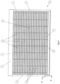
- the present invention relates to a rolling shutter, in particular a transparent rolling shutter. More specifically, it relates to a rolling shutter of the type comprising an apron composed of horizontal slats articulated together and which rolls up onto an upper horizontal shaft or drum, the edges of this articulated apron moving in lateral guides or slides.
- Such rolling shutters are generally required to be shaped and arranged to constitute rolling shutters or similar closures, or partition walls, or portions of walls, or complete walls of certain premises.
- Such curtains allow the view and passage of light from the inside to the outside and/or from the outside to the inside, even when the transparent roller blind is in the lowered position.
- the document FR-2.945.313 describes a transparent safety curtain composed of a plurality of flat horizontal transparent slats, connected together in an articulated manner.
- Each flat slat is formed of a plurality of modules joined together one after the other. It is, in addition, connected, in an articulated manner, to the one immediately above or below it by means of two different complementary joining profiles fitted to the neighboring edges of two adjacent slats and engaged one into the other.
- a breakable locking end piece is positioned at the end of each plate to stabilize the system.
- the document FR-2,941,989 describes a roller shutter slat comprising a solid core, made of a transparent or translucent material, covered on a part of each of its two faces, by a coating made of an opaque material, this coating being placed on the rear face and on the front face of said core, such that an incident light ray cannot pass through said slat from one side to the other without being stopped by at least one of the two coatings.
- Said slat has a generally curved cross-section without any details being provided on the interest of this arrangement.
- a transparent security roller shutter consisting of a plurality of horizontal flat slats hinged together by means of hinges.
- the apron of this roller shutter can be rolled up on a drum.
- the winding obtained is irregular and requires a very bulky box to house the rolled up curtain.
- the means of joining the slats hinged together seriously complicate the replacement of one or more of them if necessary.
- a transparent roller shutter consisting of separate roller shutter slats, connected to each other in a tensile-resistant manner, made of transparent plastic, which can be wound on a winding shaft and connected to each other with the interposition of curved coupling profiles, the latter being provided on their longitudinal edges with grooves for receiving the stop heads which the horizontal edges of the roller shutter slats have. Said heads can be inserted into the receiving grooves of the coupling profiles and are held there with the possibility of pivoting.
- the document GB-2.120.306 describes a rolling protection grid formed from a series of transparent blades executed in one piece and extending horizontally and metal rods pivotally connected to each other by means of preferably circular ribs extending along the upper and lower edges of each blade, which are received inside sockets formed in the metal of the rods.
- the document EP-0.445.064 describes a safety grid comprising several parallel rows of profiles, between each profile there is a plurality of elements made of transparent plastic material, and preferably polycarbonate, these elements being separated by intermediate reinforcing elements made for example of aluminum.
- the grid comprising a plurality of polycarbonate elements, the reinforcing elements being made of aluminum, they are therefore opaque which alters the transparency of the grid, in particular in the embodiment where the aluminum elements have the same dimension as the polycarbonate elements.
- the document FR-2,955,885 describes a roller shutter element consisting of an assembly of rows of modules where each module is generally rectangular in shape and the long sides of which are parallel to the winding axis of said shutter and where the modules of the same row are connected to each other using a bar or tube of circular section passing through hinges with which said long sides are provided.
- two adjacent modules are joined at their short sides and one of the short sides of a module has a lip that overlaps the short side of the adjacent module.
- the ends assembled with a simple overlap or by hooking are complex and not very compatible with a transparent curtain since they create excess thickness and vertical areas of non-transparency preventing perfect visibility and forming unsightly darkened surfaces and which also have the disadvantage of not providing complete airtightness to air, water, heat and cold.
- the document US-6,263,943 describes a modular roller shutter for shop doors and windows, consisting of a plurality of rows of slats.
- Each slat is connected by means of loops to a lower slat and an upper slat, allowing limited movement of the slats and loops so that the modular roller shutter can be rolled up and down.
- Each slat may consist of a plurality of slats having reinforcements at their ends.
- each reinforcement is provided with a coupler, the adjacent couplers having complementary coupling shapes allowing the interconnection of two adjacent slats.
- the present invention aims in particular to remedy the aforementioned drawbacks of the prior art.
- a rolling shutter according to claim 1 in particular a transparent rolling shutter, of the type comprising a roll-up apron comprising a plurality of horizontal slats hinged together, by means of joining profiles, said apron rolling onto an upper horizontal shaft or drum and its lateral edges are mounted with a capacity for movement in vertical slides or guides,
- this transparent rolling shutter being particularly remarkable in that each of said slats has a transverse profile of curved or curved shape, allowing the apron to be wound around the winding shaft or drum and essentially taking on the shape of said shaft or drum, the concavity of the slats being turned towards the winding shaft or drum when said apron is wound onto the latter, and in that each slat of the plurality of horizontal slats is made up of two or more than two modules or parts of slats joined and assembled by fitting their ends together.
- the invention makes it possible to house the winding of a roller shutter more than three meters high, around an axis with a diameter of 133 mm, in a box with a diameter of 300 mm.
- the abutting ends are provided respectively with a groove and a rib extending over the entire height of said abutting ends of the modules, said groove being nested in said rib.
- the groove and the rib have a complementary triangular profile.
- This assembly method has the advantage of not creating any excess thickness or alteration of visibility in the connection areas, and of ensuring excellent airtightness to air, water, heat and cold.
- the blades are assembled together by means of joining and articulation profiles whose opposite longitudinal edges comprise parallel grooves in which the opposite edges of said blades are engaged, for example by sliding, and, according to an advantageous embodiment, these joining and articulation profiles have a curved transverse profile whose concavity is turned towards the winding shaft or drum when said apron is wound on said shaft or drum.
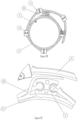
- the transparent rolling shutter is provided laterally with locking end pieces in order to prevent any lateral sliding or tearing of the slats and, according to a characteristic arrangement of the invention, these locking end pieces have a curved transverse profile whose concavity is turned towards the winding shaft or drum when said apron is wound on said shaft or drum.
- these locking end pieces comprise a closing body applied against the ends of the joining profile, so as to close the entrance to the articulation grooves provided in said joining profile.
- This body is fixed by screwing by means of at least one screw and preferably, by means of two screws screwing into cavities provided in the partition separating said grooves.
- the internal face of said locking end pieces has excess thicknesses engaged in the entrance of the articulation grooves of the joining profiles, these excess thicknesses being shaped and sized to be able to be fitted without significant play in said entrances.
- the locking tips according to the invention make it easier to hold the blades in position and to remove them if necessary, which allows significant time savings.
- the locking tips have an upper fin or cap.
- the body of the locking end pieces comprises, on its external face, partly projecting lateral wings ensuring that the apron is held in the guide rails, thus preventing it from coming unhinged against tearing forces, for example in the event of strong winds generating such forces.
- the rolling shutter according to the invention also comprises at least one ring, and preferably a plurality of rings, intended to be positioned on the winding shaft and comprising a fin surmounting a portion of the ring and arranged at a distance from the external face of said ring, so that in the situation of mounting of the curtain, the fins of the rings cover the first joining profile in order to avoid the friction of the slats against each other when rolling up the curtain and therefore the deterioration of the latter by the appearance of unsightly scratches on the transparent slats thus altering the visibility through said shutter and which would lead to fragility of said rolling shutter.
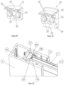
- the transparent rolling shutter 1 to which the invention applies is of the type composed of a roll-up apron 2 comprising a plurality of transparent horizontal slats 3 articulated together by means of articulation devices 9. This apron rolls up on a horizontal shaft or drum 4, placed above said apron. The opposite vertical edges of this articulated apron move in lateral guides or slides 5.
- each of said blades has a transverse profile of curved or rounded shape whose concavity 7 is turned towards the winding shaft or drum 4, when the apron 2 is wound on the winding shaft or drum ( figure 30 ).
- the lower part 1A of the apron 2 is made up of a blade 8 different from the others, called the “final” blade, which can have a flat transverse profile and a height greater than that of the blades 3.
- the lower edge of the final blade is provided with a flange 27 made of a material having an elastic deformation capacity, for example, rubber or a synthetic elastomer. This flange 27 is intended to absorb shocks when the curtain is lowered and/or to ensure sealing when said curtain is in the lowered position.
- the blades 3 can be made of any material having the desired rigidity, strength and transparency. They can for example be made of polycarbonate by a suitable injection process known to those skilled in the art. Advantageously, they can be made of polycarbonate marketed under the registered trademarks "Lexan” or “Makrolon” which, in addition to remarkable optical quality, offer good qualities of rigidity and mechanical resistance.
- An anti-UV treatment can be applied in a manner known per se, by incorporation into the material constituting the plates prior to the injection process. This treatment makes it possible to avoid the application of an anti-UV varnish after production of the plates as is usually the case.
- the slats 3 may have a relatively high height, for example of the order of 85 mm, much higher than that of traditional transparent roller shutter slats. They may have a thickness of the order of 4 mm, giving them great strength while allowing a certain flexion capacity and shape memory thanks to which the transparent roller shutter according to the invention has good resistance to impacts and attempted break-ins. Said slats may be covered with a varnish for optimum resistance to friction and scratches.
- They can have excellent transparency qualities or be slightly tinted or not, or translucent, or opaque, or glittery.
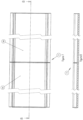
- the blades 3 are made up of several modules or parts 3A, 3B, 3C..., joined together.
- the final lower blade 8 may be made of aluminum by any suitable extrusion process.
- the horizontal slats made up of several modules or parts of slats 3A, 3B, 3C..., joined together, can have lengths greater than 6 meters, and allow the creation of rolling shutters of substantially identical lengths.
- the blades 3 are connected to each other by means of a joining and articulation profile 9.
- these joining profiles are made of a material having the desirable rigidity and robustness, for example, extruded aluminum.
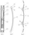
- profiles 9 have an approximately rectangular and slightly curved or arched transverse profile whose concavity 10 is turned towards the winding shaft or drum when said apron 2 is wound on said shaft or drum ( figure 30 ).
- junction profiles 9 are made in one piece, with a length corresponding to the length of the blades made up of several butted modules. They comprise two opposite longitudinal grooves 11A and 11B, extending along their edges, over their entire length. These grooves 11A and 11B have a generally circular profile and are open towards the outside.
- This opening constituted by a longitudinal slot 23, has a width less than the diameter of the assembly rods or strips 12 of the blades 3, so that said rods constituting the upper and lower edges of the blades can be introduced by sliding into the grooves 11A and/or 11B of the joining profiles 9 and then be held in said grooves, with a pivoting ability, by the retracting edges 23A, 23B delimiting said slot 23.
- the junction bar 13 abuts against one or other of the edges 23A and 23B of the slot 23, which limits the amplitude of the pivoting of said blades.
- the blades 3 or the parts of blades 3A, 3B, 3C... properly speaking, have a step 13' projecting from the convex surface of said blades 3 or parts of blades 3A, 3B, 3C..., these longitudinal steps 13' thus constitute stops limiting the pivoting of the latter relative to the junction profiles 9.
- a C-shaped soundproofing seal 14 for example made of polyvinyl chloride (PVC), is housed in the grooves 11A and 11B.
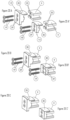
- the butted modules or parts of blades 3A, 3B, 3C... are assembled by interlocking.
- the opposite abutting ends of the modules are provided respectively with a groove 16 and a rib 17 extending over the entire height of said abutting ends.
- the groove 16 and the rib 17 have a triangular profile. More precisely, the groove 16 has a V-shaped profile, while the rib 17 has a beveled profile fitting exactly into said groove.
- the blades 3 are held in the junction and articulation profiles 9 by means of locking end pieces 15 preventing any lateral sliding of said blades relative to said profiles.
- these locking end pieces 15 comprise a closing body 18 applied against the ends 9A and 9B of the joining profiles 9 so as to close the entrance to the articulation grooves 11A and 11B provided in said joining profiles.
- This body is fixed against the end 9A or 9B of the joining profiles 9, by screwing by means of at least one screw 19 and, preferably, by means of two self-drilling screws screwing into the holes 29 that said end piece has and into cavities 20 provided in the partition 21 separating said grooves 11A or 11B, parallel to the latter.
- These locking end pieces have an approximately rectangular and slightly curved transverse profile, the concavity 28 of which is turned towards the drive shaft or drum 4, when the apron 2 is wound onto said winding shaft or drum.
- the internal face of the locking end pieces has excess thicknesses or bosses 22 engaged in the entrance of the articulation grooves 11A and 11B of the joining profiles 9.
- These bosses 22 of generally cylindrical shape are shaped and dimensioned so that they can be fitted without significant play in said entrances. They make it possible to hold the locking end pieces 15 on the ends of the joining profiles 9 before fixing the latter by means of self-drilling screws 19.
- the locking end pieces have an upper fin or cap 30 constituting a support for the transparent shutter when the windings are superimposed so as to prevent the slats from rubbing against each other when the curtain is wound and therefore the deterioration of the latter by the appearance of unsightly scratches on the transparent slats, thus altering visibility through said shutter and which would cause said roller shutter to become fragile.
- the locking tips 15 are, for example, made of PVC or any other suitable material.
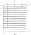
- the upper part 1B of the apron 2 is constituted by a first blade 34 similar to the blades 3.
- the upper edge of the first blade is provided with at least one, and preferably several fixing plates 35 having a hole 36 for the passage of a fixing screw 37.
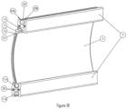
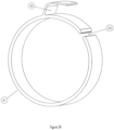
- the rolling shutter according to the invention also comprises at least one ring 31, intended to be placed on the winding shaft 4.
- This ring is made up of a ring of a diameter identical, or approximately identical to that of the winding shaft or drum 4, comprising a slot 33 allowing its opening and its deformation by spreading the edges of said slot ( Figure 25A ).
- This ring is also provided with a fin 32 surmounting a portion of the ring 31 and arranged at a distance from the external face of said ring, so that when the curtain is being mounted, the fins (32) of the rings (31) cover the first junction profile (9) in order to prevent the slats from rubbing against each other when the curtain is being rolled up and therefore the deterioration of the latter by the appearance of unsightly scratches on the transparent slats, thus impairing visibility through said shutter and which would lead to fragility of said roller shutter.
- rings 31 are arranged on the winding shaft 4 so as to coincide with the intersection between two adjacent modules 3A, 3B, 3C, ....
- winding rings are for example made of PVC or any other suitable elastic material allowing their deformation by spacing when they are placed on the winding shaft or drum 4 and the automatic resumption of their circular shape once arranged around said winding shaft.
- the vertical guide slides have a general U-shaped profile, the open side of which defines a longitudinal opening 24, extending over the entire height of said guide slides.
- a vertical guide corridor 25 is provided between the front 5a and rear 5b re-entrant wings of the slides 5 and the ends of the blades 3 and 8 and of the profiles 9 move in said vertical corridor.
- the entrance to the vertical passages 25 in which the ends of the blades 3 and 8 and the joining profiles 9 move is delimited by retracting wings extending over the entire height of the guide slides 5 and, according to another characteristic arrangement, at least certain blocking end pieces 15' are shaped to resist any tearing force resulting, for example, from very strong winds or attempted break-ins.
- these blocking end pieces 15' are provided with lateral wings or projecting parts 26, of a width greater than the width of the entrance to the guide passage.
- the projecting parts of the end pieces 15' come into abutment against the opposite retracting wings 5a and 5b delimiting the vertical entrance opening of the guide passages. This device prevents the blades from being torn off when the weather conditions are very bad by ensuring better support for the apron in the guide rails.
Landscapes
- Engineering & Computer Science (AREA)
- Structural Engineering (AREA)
- Architecture (AREA)
- Civil Engineering (AREA)
- Operating, Guiding And Securing Of Roll- Type Closing Members (AREA)
Claims (13)
- Transparenter Rollladen (1) mit rollbarer Schürze (2) um eine Welle oder horizontal Trommel (4), die über dieser Schürze angebracht ist, wobei der Rollladen mehrere transparente horizontale Lamellen (3) aufweist, die mit Gelenkvorrichtungen (9) gelenkig miteinander verbunden sind, wobei sich die gegenüberliegenden vertikalen Ränder der gelenkig verbundenen Schürze in Seitenführungen oder Führungsleisten (5) bewegen, jede Lamelle (3) der zahlreichen horizontalen Lamellen aus zwei oder mehreren Modulen oder Teilen von Lamellen (3A, 3B, 3C...) besteht, die durch Ineinanderstecken ihrer Enden miteinander verbunden und zusammengefügt sind und die Stoßenden der Module jeweils mit einer Nut (16) und einer Rippe (17) ausgestattet sind, die sich auf die gesamte Höhe der Stoßenden der Module erstrecken,dadurch gekennzeichnet, dass jede Lamelle ein geschwungenes Querprofil aufweist, dessen Vertiefung sich zur Welle oder Wickeltrommel (4) dreht, wenn die Schürze (2) an der Welle oder Trommel auf- oder abgerollt wird,und dadurch, dass die Nut (16) und die Rille (17) ein komplementäres dreieckiges Profil aufweisen, so dass dieser Verbund in den Verbindungszonen der Module keine Überdicke erzeugt.
- Transparenter Rollladen nach Anspruch 1, dadurch gekennzeichnet, dass die gegenüberliegenden Längsränder der Lamellen (3) mit Befestigungs- und Gelenkleisten (12) mit kreisförmigem Querschnitt ausgestattet sind, die über einen Stab (13) von geringer Höhe mit den Längsrändern verbunden sind, und dass die Lamellen mit Verbindungs- und Gelenkprofilen (9) zusammengefügt sind, deren Ränder mit offenen Längsrillen (11A, 11B) ausgestattet sind, die sich entlang der Profile erstrecken, das heißt eine obere Rille (11A) und eine untere Rille (11B) mit kreisförmigem Querschnitt, in denen die Leisten (12) mit kreisförmigem Querschnitt der beiden angrenzenden Lamellen stützend gelagert und gehalten werden, welche durch Einschieben in diese Rillen eingeführt werden, wobei diese Verbindungs- und Gelenkprofile (9) ein gewölbtes Querprofil aufweisen, dessen Vertiefung (10) sich zur Welle oder Wickeltrommel dreht, wenn die Schürze an der Welle oder Trommel auf- oder abgerollt wird.
- Transparenter Rollladen nach Anspruch 2, dadurch gekennzeichnet, dass die Längsrillen (11A, 11B) der Verbindungsprofile eingezogene Ränder (23A, 23B) aufweisen, die die Öffnung dieser Rillen abgrenzen.
- Transparenter Rollladen nach den Ansprüchen 2 und 3, dadurch gekennzeichnet, dass eine C-förmige schalldämmende Dichtung (14) in den Rillen (11A, 11B) untergebracht ist.
- Transparenter Rollladen nach einem der Ansprüche 1 bis 4, dadurch gekennzeichnet, dass die Lamellen (3) des transparenten Rollladens (1) durch ein Spritzgussverfahren aus Polycarbonat ausgeführt sind.
- Transparenter Rollladen nach Anspruch 5, dadurch gekennzeichnet, dass die Lamellen (3) des transparenten Rollladens aus Polycarbonat des Typs "Lexan" oder "Makrolon" ausgeführt sind (eingetragene Marken).
- Transparenter Rollladen nach einem der Ansprüche 1 bis 6, dadurch gekennzeichnet, dass die Verbindungs- und Gelenkprofile (9) aus stranggepresstem Aluminium ausgeführt sind.
- Transparenter Rollladen nach einem der Ansprüche 1 bis 7, dadurch gekennzeichnet, dass die Endlamelle (8) ein flaches Querprofil und eine größere Höhe als die anderen Lamellen (3) aufweist, wobei die Endlamelle (8) aus Aluminium ausgeführt ist.
- Transparenter Rollladen nach einem der Ansprüche 1 bis 8, in dem die Lamellen (3) in Verbindungs- und Gelenkprofilen (9) über Sperrendstücke (15) gehalten werden, dadurch gekennzeichnet, dass die Sperrendstücke (15) einen Schließkörper (18) enthalten, der gegen die Enden (9A, 9B) des Verbindungsprofils (9) so aufgebracht wird, dass er den Eingang der Gelenkrillen (11A, 11B), die im Verbindungsprofil angeordnet sind, verschließt, wobei der Körper am Ende (9A oder 9B) der Verbindungsprofile (9) durch Verschraubung über eine Schraube (19) und vorzugsweise über zwei Selbstbohrschrauben befestigt ist, die sich einerseits in die Löcher (29), die das Sperrendstück (15) aufweist, und andererseits in die in der Trennwand (21) angeordneten Vertiefungen (20), die die Rinnen (11A oder 11B) abtrennen und parallel dazu verlaufen, einschrauben.
- Transparenter Rollladen nach Anspruch 9, dadurch gekennzeichnet, dass die Innenseite der Sperrendstücke Überdicken (22) aufweist, die in den Eingang der Gelenkrillen (11A, 11B) eingreifen und das Halten der Endstücke gegen die Enden der Verbindungsprofile vor der Befestigung durch Verschraubung der Endstücke ermöglichen.
- Transparenter Rollladen nach einem der Ansprüche 9 oder 10, dadurch gekennzeichnet, dass die Sperrendstücke eine Oberrippe oder Kappe (30) aufweisen.
- Transparenter Rollladen nach einem der Ansprüche 1 bis 11, nach dem der Eingang der vertikalen Gänge (25), in denen sich die Lamellenenden (3 und 8) und Verbindungsprofile (9) bewegen, von eingezogenen Flügeln abgegrenzt wird, die sich auf die gesamte Höhe der Führungsschienen (5) erstrecken, und dadurch gekennzeichnet, dass zumindest einige Sperrendstücke (15) so angepasst sind, dass sie jeglicher Reißkraft standhalten, die beilspielsweise aus sehr starken Winden oder Einbruchversuchen entsteht, wobei diese Sperrendstücke (15') mit Seitenflügeln oder überstehenden Teilen (26) mit einer größeren Breite als der Breite des Eingangs des Führungsgangs ausgestattet sind, so dass bei dem Versuch, die Schürze mit Gewalt aufzuhebeln, die überstehenden Teile der Endstücke (15') gegen die gegenüberliegenden eingezogenen Flügel (5a und 5b) anschlagen, die die vertikale Öffnung des Eingangs der Führungsgänge abgrenzen.
- Transparenter Rollladen nach einem der Ansprüche 1 bis 12, dadurch gekennzeichnet, dass er mindestens einen Ring (31), vorzugsweise mehrere Ringe (31), aufweist, die an der Wickelwelle positioniert werden sollen und einen Flügel (32) enthalten, der einen Teil des Rings überdeckt (31) und in einem Abstand von der Außenseite des Rings angeordnet ist, so dass bei der Montage des Rollladens die Flügel (32) der Ringe (31) das erste Verbindungsprofil (9) umgeben, um ein Aneinanderreiben der Lamellen beim Auf- und Abrollen des Rollladens und somit die Beschädigung der Lamellen durch das Entstehen unästhetischer Kratzer an den transparenten Lamellen zu vermeiden, die dadurch die Sicht durch den Rollladen verschlechtern und zu einer Brüchigkeit des Rollladens führen würden.
Applications Claiming Priority (2)
| Application Number | Priority Date | Filing Date | Title |
|---|---|---|---|
| FR1256423A FR2992994B1 (fr) | 2012-07-04 | 2012-07-04 | Rideau roulant transparent |
| PCT/FR2013/051568 WO2014006328A2 (fr) | 2012-07-04 | 2013-07-03 | Rideau roulant transparent |
Publications (3)
| Publication Number | Publication Date |
|---|---|
| EP2900893A2 EP2900893A2 (de) | 2015-08-05 |
| EP2900893B1 EP2900893B1 (de) | 2017-09-06 |
| EP2900893B2 true EP2900893B2 (de) | 2025-03-26 |
Family
ID=47049258
Family Applications (1)
| Application Number | Title | Priority Date | Filing Date |
|---|---|---|---|
| EP13813242.8A Active EP2900893B2 (de) | 2012-07-04 | 2013-07-03 | Transparenter rollladen |
Country Status (5)
| Country | Link |
|---|---|
| US (1) | US20150368965A1 (de) |
| EP (1) | EP2900893B2 (de) |
| CA (1) | CA2876401A1 (de) |
| FR (1) | FR2992994B1 (de) |
| WO (1) | WO2014006328A2 (de) |
Families Citing this family (7)
| Publication number | Priority date | Publication date | Assignee | Title |
|---|---|---|---|---|
| CN106050106A (zh) * | 2016-07-28 | 2016-10-26 | 苏州信利昌电子材料有限公司 | 一种自动化霜卷帘门 |
| EP3805513B1 (de) * | 2017-05-31 | 2023-04-26 | Seuster KG | Rolltor |
| RU190319U1 (ru) * | 2019-04-19 | 2019-06-26 | Евгений Викторович Федченко | Рольставни |
| DE102019125204A1 (de) * | 2019-09-19 | 2021-03-25 | Seuster Kg | Rolltor |
| US11208840B1 (en) * | 2019-11-05 | 2021-12-28 | Goff's Enterprises, Inc. | Soft roll-up door with fall protection |
| JP7628011B2 (ja) | 2020-10-27 | 2025-02-07 | 国立大学法人大阪大学 | 建築用シャッター装置におけるシャッターカーテンのスラット接合方法、シャッターカーテンの補修方法およびシャッターカーテンのスラット接合装置 |
| CN114275638B (zh) * | 2022-01-19 | 2023-04-25 | 无锡星智数服科技有限公司 | 一种智慧物流仓储实时监测显示设备 |
Citations (14)
| Publication number | Priority date | Publication date | Assignee | Title |
|---|---|---|---|---|
| US4345635A (en) † | 1980-08-29 | 1982-08-24 | Solomon Martin D | Rolling protective gate for store fronts or the like |
| US4690193A (en) † | 1985-08-07 | 1987-09-01 | The Standard Oil Company | Rolling shutter construction |
| US4723588A (en) † | 1984-07-05 | 1988-02-09 | Rueppel Kurt | Roller shutter slat of the so-called mini-size made from a roll-shaped aluminium strip |
| EP0310548A2 (de) † | 1987-09-26 | 1989-04-05 | Schweizerische Aluminium Ag | Rolladen oder Rolltor |
| US4979553A (en) † | 1989-02-10 | 1990-12-25 | Wayne-Dalton Corporation | Slat assembly and curtain for rolling door |
| CN2528906Y (zh) † | 2001-12-11 | 2003-01-01 | 庄文泉 | 格子式卷帘门 |
| KR20070102130A (ko) † | 2006-04-14 | 2007-10-18 | 김재영 | 투명 셔터 |
| US7357171B2 (en) † | 2004-03-17 | 2008-04-15 | Qmi Security Solutions | Low-clearance shutter slat |
| GR1006384B (el) † | 2008-02-28 | 2009-05-07 | Γαβριηλ Κολλιας | Κλειστο στεγανο διαφανες ρολο με αρθρωτα διαφανη φυλλα μεγαλης ορατοτητας |
| AU2009201265A1 (en) † | 2008-04-15 | 2009-10-29 | Ezi Roll Doors Australia Pty Ltd | Roller Shutter or Multi-Fold Door Fabrication |
| KR20090122776A (ko) † | 2008-05-26 | 2009-12-01 | 김진봉 | 투명셔터 |
| WO2010053357A1 (en) † | 2008-11-04 | 2010-05-14 | Beulen Allegonda Petronella Ge | Roller shutter having a smooth outer surface |
| WO2011095707A1 (fr) † | 2010-02-03 | 2011-08-11 | Visionroll | Nouvel élément, ou module, de volet roulant, ainsi que le volet formé à l'aide de ces modules |
| EP2251522B1 (de) † | 2009-05-07 | 2011-10-05 | Profilmar | Durchsichtiger Sicherheitsvorhang |
Family Cites Families (18)
| Publication number | Priority date | Publication date | Assignee | Title |
|---|---|---|---|---|
| US2858582A (en) * | 1953-12-01 | 1958-11-04 | Ohio Commw Eng Co | Building material |
| US2831537A (en) * | 1955-11-23 | 1958-04-22 | Adolph P Ritter | Overhead flexible door |
| US3419064A (en) * | 1966-12-12 | 1968-12-31 | Oddicini Renzo | Articulated structure particularly for partitions |
| US3734161A (en) * | 1970-08-26 | 1973-05-22 | E Pierce | Door construction |
| US4332287A (en) * | 1980-05-13 | 1982-06-01 | Dynaflair Corporation Canada, Inc. | Rolling safety doors |
| GB2120306B (en) * | 1982-05-13 | 1986-01-15 | Martin David Solomon | Rolling gate |
| US4833855A (en) * | 1987-04-27 | 1989-05-30 | Winter Amos G Iv | Prefabricated panel having a joint thereon |
| DE3915233A1 (de) * | 1988-07-05 | 1990-11-15 | Andre Janssen | Rolladen fuer oeffnungsabschluesse |
| US5247773A (en) * | 1988-11-23 | 1993-09-28 | Weir Richard L | Building structures |
| NO177359C (no) * | 1990-03-01 | 1995-08-30 | Jsa Sikring Aps | Opprullbart sikkerhetsgitter |
| US5448865A (en) * | 1993-08-20 | 1995-09-12 | Palmersten; Michael J. | Panel interlocking means with stiffener |
| US5680735A (en) * | 1995-03-08 | 1997-10-28 | Bates; Gary Grant | Modular buiding system |
| US5782282A (en) * | 1997-07-17 | 1998-07-21 | Chen; Chang Than | Foldable door for closet |
| CN2312316Y (zh) * | 1997-12-17 | 1999-03-31 | 黎文志 | 店铺门窗的卷帘 |
| JP3950761B2 (ja) * | 2001-08-23 | 2007-08-01 | アイセル株式会社 | シャッタ |
| US7650918B2 (en) * | 2003-02-14 | 2010-01-26 | Tapco International Corporation | Method of manufacturing a modular shutter assembly |
| US20090071082A1 (en) * | 2007-09-13 | 2009-03-19 | Van Der Kort Fred | Enhanced protection and security shutter system |
| US8286399B2 (en) * | 2010-01-20 | 2012-10-16 | Hill Phoenix, Inc. | Structural insulated panel system |
-
2012
- 2012-07-04 FR FR1256423A patent/FR2992994B1/fr active Active
-
2013
- 2013-07-03 US US14/412,583 patent/US20150368965A1/en not_active Abandoned
- 2013-07-03 EP EP13813242.8A patent/EP2900893B2/de active Active
- 2013-07-03 CA CA2876401A patent/CA2876401A1/fr not_active Abandoned
- 2013-07-03 WO PCT/FR2013/051568 patent/WO2014006328A2/fr not_active Ceased
Patent Citations (14)
| Publication number | Priority date | Publication date | Assignee | Title |
|---|---|---|---|---|
| US4345635A (en) † | 1980-08-29 | 1982-08-24 | Solomon Martin D | Rolling protective gate for store fronts or the like |
| US4723588A (en) † | 1984-07-05 | 1988-02-09 | Rueppel Kurt | Roller shutter slat of the so-called mini-size made from a roll-shaped aluminium strip |
| US4690193A (en) † | 1985-08-07 | 1987-09-01 | The Standard Oil Company | Rolling shutter construction |
| EP0310548A2 (de) † | 1987-09-26 | 1989-04-05 | Schweizerische Aluminium Ag | Rolladen oder Rolltor |
| US4979553A (en) † | 1989-02-10 | 1990-12-25 | Wayne-Dalton Corporation | Slat assembly and curtain for rolling door |
| CN2528906Y (zh) † | 2001-12-11 | 2003-01-01 | 庄文泉 | 格子式卷帘门 |
| US7357171B2 (en) † | 2004-03-17 | 2008-04-15 | Qmi Security Solutions | Low-clearance shutter slat |
| KR20070102130A (ko) † | 2006-04-14 | 2007-10-18 | 김재영 | 투명 셔터 |
| GR1006384B (el) † | 2008-02-28 | 2009-05-07 | Γαβριηλ Κολλιας | Κλειστο στεγανο διαφανες ρολο με αρθρωτα διαφανη φυλλα μεγαλης ορατοτητας |
| AU2009201265A1 (en) † | 2008-04-15 | 2009-10-29 | Ezi Roll Doors Australia Pty Ltd | Roller Shutter or Multi-Fold Door Fabrication |
| KR20090122776A (ko) † | 2008-05-26 | 2009-12-01 | 김진봉 | 투명셔터 |
| WO2010053357A1 (en) † | 2008-11-04 | 2010-05-14 | Beulen Allegonda Petronella Ge | Roller shutter having a smooth outer surface |
| EP2251522B1 (de) † | 2009-05-07 | 2011-10-05 | Profilmar | Durchsichtiger Sicherheitsvorhang |
| WO2011095707A1 (fr) † | 2010-02-03 | 2011-08-11 | Visionroll | Nouvel élément, ou module, de volet roulant, ainsi que le volet formé à l'aide de ces modules |
Non-Patent Citations (7)
| Title |
|---|
| catalogue de volets roulants intitulé «Gamme de volets roulants destinés a la rénovation, pour fenêtre et porte-fenétre» distribué par la Société LAKAL et mis a la disposition du public le 16 février 2011 † |
| catalogue de volets roulants intitulé «Volets roulants Bloc Baie,Bloc Baie Aluminium », distribué par la Société FLO Fermetures Loire-Ocean - LAGON et mis à la disposition du public en juin 2012 † |
| catalogue intitulé « Volets roulants », distribué par la Société France Fermetures et mis à la disposition du public en mars 2009 † |
| manuel d'installation de volets roulants intitulé «Shutter Installation Instructions» qui a été mis à la disposition du public en août 2006 † |
| publication d?un modèle international n° DM/074686 (Visionroll) † |
| publication d'un modèle français n° 2010/0764 (Visionroll) † |
| traduction en anglais du modèle d?utilité chinois CN 2 528 906 † |
Also Published As
| Publication number | Publication date |
|---|---|
| EP2900893B1 (de) | 2017-09-06 |
| US20150368965A1 (en) | 2015-12-24 |
| WO2014006328A3 (fr) | 2015-04-09 |
| FR2992994B1 (fr) | 2017-09-22 |
| FR2992994A1 (fr) | 2014-01-10 |
| WO2014006328A2 (fr) | 2014-01-09 |
| EP2900893A2 (de) | 2015-08-05 |
| CA2876401A1 (fr) | 2014-01-09 |
Similar Documents
| Publication | Publication Date | Title |
|---|---|---|
| EP2900893B2 (de) | Transparenter rollladen | |
| EP0441928B1 (de) | Fassadenpaneel mit metallgestell und bekleideter fassade | |
| EP1129270B1 (de) | Tür oder fenster mit verdecktem flügel | |
| EP1964990A1 (de) | Winkelelement für teleskopierenden Unterstand | |
| EP0818601A1 (de) | Rolladen mit dünnen lamellen, die zusammengefügt und mit geraden Kanten versehen sind | |
| FR2935406A1 (fr) | Abri telescopique guide en partie haute | |
| FR2784708A1 (fr) | Fenetre ou porte-fenetre a frappe a ouvrant(s) cache(s) | |
| FR2981115A1 (fr) | Element de coffrage pour un volet roulant, destine a etre pose au niveau de la traverse haute d'un dormant rapporte au sein d'une baie de batiment | |
| WO2014202558A1 (fr) | Dispositif de protection de batiment, kit de protection et procede de mise en oeuvre | |
| FR2912765A1 (fr) | Abri telescopique a facade mobile integrant des elements de manutention | |
| EP2531689B1 (de) | Neuartiges element oder modul für einen rollladen und aus diesen modulen gebildeter rollladen | |
| FR3020649A1 (fr) | Abri de piscine a modules telescopiques comprenant un mecanisme de deplacement ameliore des modules | |
| FR2991706A1 (fr) | Cadre de menuiserie equipe d'un dispositif a vitrage respirant | |
| FR3003885B1 (fr) | Tunnel de protection destine a proteger un tapis roulant de transport de pietons ou skieurs | |
| FR2784710A1 (fr) | Fenetre ou porte-fenetre a frappe a ouvrant(s) cache(s) | |
| FR2891299A1 (fr) | Systeme de fermeture a galandage d'une ouverture pratiquee dans un mur. | |
| FR2937843A1 (fr) | Paravent medical | |
| FR2634512A1 (fr) | Dispositif d'etancheite et de structures de baies coulissantes et de verandas en bois | |
| FR2912764A1 (fr) | Abri telescopique a hauteur de roulement multiple. | |
| FR3150225A1 (fr) | Volet de piscine | |
| WO2012066198A1 (fr) | Structure poussante d'une nappe souple | |
| FR2823652A1 (fr) | Lame profilee pour fermeture a rideau pourvue de moyens de limitation de bruit | |
| FR3020650A1 (fr) | Abri de piscine a modules telescopiques comprenant un systeme de verrouillage des modules | |
| FR2584123A1 (fr) | Edifice leger demontable tel que kiosque de vente en plein air | |
| FR2862686A1 (fr) | Module d'abri, element de couverture et application a des abris de piscine |
Legal Events
| Date | Code | Title | Description |
|---|---|---|---|
| PUAI | Public reference made under article 153(3) epc to a published international application that has entered the european phase |
Free format text: ORIGINAL CODE: 0009012 |
|
| 17P | Request for examination filed |
Effective date: 20150113 |
|
| AK | Designated contracting states |
Kind code of ref document: A2 Designated state(s): AL AT BE BG CH CY CZ DE DK EE ES FI FR GB GR HR HU IE IS IT LI LT LU LV MC MK MT NL NO PL PT RO RS SE SI SK SM TR |
|
| AX | Request for extension of the european patent |
Extension state: BA ME |
|
| DAX | Request for extension of the european patent (deleted) | ||
| GRAP | Despatch of communication of intention to grant a patent |
Free format text: ORIGINAL CODE: EPIDOSNIGR1 |
|
| STAA | Information on the status of an ep patent application or granted ep patent |
Free format text: STATUS: GRANT OF PATENT IS INTENDED |
|
| INTG | Intention to grant announced |
Effective date: 20170303 |
|
| GRAS | Grant fee paid |
Free format text: ORIGINAL CODE: EPIDOSNIGR3 |
|
| GRAA | (expected) grant |
Free format text: ORIGINAL CODE: 0009210 |
|
| STAA | Information on the status of an ep patent application or granted ep patent |
Free format text: STATUS: THE PATENT HAS BEEN GRANTED |
|
| AK | Designated contracting states |
Kind code of ref document: B1 Designated state(s): AL AT BE BG CH CY CZ DE DK EE ES FI FR GB GR HR HU IE IS IT LI LT LU LV MC MK MT NL NO PL PT RO RS SE SI SK SM TR |
|
| REG | Reference to a national code |
Ref country code: GB Ref legal event code: FG4D Free format text: NOT ENGLISH |
|
| REG | Reference to a national code |
Ref country code: CH Ref legal event code: EP Ref country code: AT Ref legal event code: REF Ref document number: 926114 Country of ref document: AT Kind code of ref document: T Effective date: 20170915 |
|
| REG | Reference to a national code |
Ref country code: IE Ref legal event code: FG4D Free format text: LANGUAGE OF EP DOCUMENT: FRENCH |
|
| REG | Reference to a national code |
Ref country code: DE Ref legal event code: R096 Ref document number: 602013026307 Country of ref document: DE |
|
| REG | Reference to a national code |
Ref country code: NL Ref legal event code: MP Effective date: 20170906 |
|
| REG | Reference to a national code |
Ref country code: LT Ref legal event code: MG4D |
|
| PG25 | Lapsed in a contracting state [announced via postgrant information from national office to epo] |
Ref country code: FI Free format text: LAPSE BECAUSE OF FAILURE TO SUBMIT A TRANSLATION OF THE DESCRIPTION OR TO PAY THE FEE WITHIN THE PRESCRIBED TIME-LIMIT Effective date: 20170906 Ref country code: SE Free format text: LAPSE BECAUSE OF FAILURE TO SUBMIT A TRANSLATION OF THE DESCRIPTION OR TO PAY THE FEE WITHIN THE PRESCRIBED TIME-LIMIT Effective date: 20170906 Ref country code: HR Free format text: LAPSE BECAUSE OF FAILURE TO SUBMIT A TRANSLATION OF THE DESCRIPTION OR TO PAY THE FEE WITHIN THE PRESCRIBED TIME-LIMIT Effective date: 20170906 Ref country code: LT Free format text: LAPSE BECAUSE OF FAILURE TO SUBMIT A TRANSLATION OF THE DESCRIPTION OR TO PAY THE FEE WITHIN THE PRESCRIBED TIME-LIMIT Effective date: 20170906 Ref country code: NO Free format text: LAPSE BECAUSE OF FAILURE TO SUBMIT A TRANSLATION OF THE DESCRIPTION OR TO PAY THE FEE WITHIN THE PRESCRIBED TIME-LIMIT Effective date: 20171206 |
|
| REG | Reference to a national code |
Ref country code: AT Ref legal event code: MK05 Ref document number: 926114 Country of ref document: AT Kind code of ref document: T Effective date: 20170906 |
|
| PG25 | Lapsed in a contracting state [announced via postgrant information from national office to epo] |
Ref country code: ES Free format text: LAPSE BECAUSE OF FAILURE TO SUBMIT A TRANSLATION OF THE DESCRIPTION OR TO PAY THE FEE WITHIN THE PRESCRIBED TIME-LIMIT Effective date: 20170906 Ref country code: LV Free format text: LAPSE BECAUSE OF FAILURE TO SUBMIT A TRANSLATION OF THE DESCRIPTION OR TO PAY THE FEE WITHIN THE PRESCRIBED TIME-LIMIT Effective date: 20170906 Ref country code: GR Free format text: LAPSE BECAUSE OF FAILURE TO SUBMIT A TRANSLATION OF THE DESCRIPTION OR TO PAY THE FEE WITHIN THE PRESCRIBED TIME-LIMIT Effective date: 20171207 Ref country code: RS Free format text: LAPSE BECAUSE OF FAILURE TO SUBMIT A TRANSLATION OF THE DESCRIPTION OR TO PAY THE FEE WITHIN THE PRESCRIBED TIME-LIMIT Effective date: 20170906 Ref country code: BG Free format text: LAPSE BECAUSE OF FAILURE TO SUBMIT A TRANSLATION OF THE DESCRIPTION OR TO PAY THE FEE WITHIN THE PRESCRIBED TIME-LIMIT Effective date: 20171206 |
|
| PG25 | Lapsed in a contracting state [announced via postgrant information from national office to epo] |
Ref country code: NL Free format text: LAPSE BECAUSE OF FAILURE TO SUBMIT A TRANSLATION OF THE DESCRIPTION OR TO PAY THE FEE WITHIN THE PRESCRIBED TIME-LIMIT Effective date: 20170906 |
|
| PG25 | Lapsed in a contracting state [announced via postgrant information from national office to epo] |
Ref country code: PL Free format text: LAPSE BECAUSE OF FAILURE TO SUBMIT A TRANSLATION OF THE DESCRIPTION OR TO PAY THE FEE WITHIN THE PRESCRIBED TIME-LIMIT Effective date: 20170906 Ref country code: CZ Free format text: LAPSE BECAUSE OF FAILURE TO SUBMIT A TRANSLATION OF THE DESCRIPTION OR TO PAY THE FEE WITHIN THE PRESCRIBED TIME-LIMIT Effective date: 20170906 Ref country code: RO Free format text: LAPSE BECAUSE OF FAILURE TO SUBMIT A TRANSLATION OF THE DESCRIPTION OR TO PAY THE FEE WITHIN THE PRESCRIBED TIME-LIMIT Effective date: 20170906 |
|
| PG25 | Lapsed in a contracting state [announced via postgrant information from national office to epo] |
Ref country code: AT Free format text: LAPSE BECAUSE OF FAILURE TO SUBMIT A TRANSLATION OF THE DESCRIPTION OR TO PAY THE FEE WITHIN THE PRESCRIBED TIME-LIMIT Effective date: 20170906 Ref country code: SK Free format text: LAPSE BECAUSE OF FAILURE TO SUBMIT A TRANSLATION OF THE DESCRIPTION OR TO PAY THE FEE WITHIN THE PRESCRIBED TIME-LIMIT Effective date: 20170906 Ref country code: EE Free format text: LAPSE BECAUSE OF FAILURE TO SUBMIT A TRANSLATION OF THE DESCRIPTION OR TO PAY THE FEE WITHIN THE PRESCRIBED TIME-LIMIT Effective date: 20170906 Ref country code: SM Free format text: LAPSE BECAUSE OF FAILURE TO SUBMIT A TRANSLATION OF THE DESCRIPTION OR TO PAY THE FEE WITHIN THE PRESCRIBED TIME-LIMIT Effective date: 20170906 Ref country code: IT Free format text: LAPSE BECAUSE OF FAILURE TO SUBMIT A TRANSLATION OF THE DESCRIPTION OR TO PAY THE FEE WITHIN THE PRESCRIBED TIME-LIMIT Effective date: 20170906 Ref country code: IS Free format text: LAPSE BECAUSE OF FAILURE TO SUBMIT A TRANSLATION OF THE DESCRIPTION OR TO PAY THE FEE WITHIN THE PRESCRIBED TIME-LIMIT Effective date: 20180106 |
|
| REG | Reference to a national code |
Ref country code: DE Ref legal event code: R026 Ref document number: 602013026307 Country of ref document: DE |
|
| PLBI | Opposition filed |
Free format text: ORIGINAL CODE: 0009260 |
|
| PLAX | Notice of opposition and request to file observation + time limit sent |
Free format text: ORIGINAL CODE: EPIDOSNOBS2 |
|
| 26 | Opposition filed |
Opponent name: SOCIETE PROFILMAR Effective date: 20180606 |
|
| REG | Reference to a national code |
Ref country code: FR Ref legal event code: PLFP Year of fee payment: 6 |
|
| PG25 | Lapsed in a contracting state [announced via postgrant information from national office to epo] |
Ref country code: DK Free format text: LAPSE BECAUSE OF FAILURE TO SUBMIT A TRANSLATION OF THE DESCRIPTION OR TO PAY THE FEE WITHIN THE PRESCRIBED TIME-LIMIT Effective date: 20170906 |
|
| REG | Reference to a national code |
Ref country code: FR Ref legal event code: CL Name of requester: CRYSTAL VISION, FR Effective date: 20180629 |
|
| PG25 | Lapsed in a contracting state [announced via postgrant information from national office to epo] |
Ref country code: SI Free format text: LAPSE BECAUSE OF FAILURE TO SUBMIT A TRANSLATION OF THE DESCRIPTION OR TO PAY THE FEE WITHIN THE PRESCRIBED TIME-LIMIT Effective date: 20170906 |
|
| PG25 | Lapsed in a contracting state [announced via postgrant information from national office to epo] |
Ref country code: MT Free format text: LAPSE BECAUSE OF FAILURE TO SUBMIT A TRANSLATION OF THE DESCRIPTION OR TO PAY THE FEE WITHIN THE PRESCRIBED TIME-LIMIT Effective date: 20170906 |
|
| PLBB | Reply of patent proprietor to notice(s) of opposition received |
Free format text: ORIGINAL CODE: EPIDOSNOBS3 |
|
| REG | Reference to a national code |
Ref country code: CH Ref legal event code: PL |
|
| GBPC | Gb: european patent ceased through non-payment of renewal fee |
Effective date: 20180703 |
|
| PG25 | Lapsed in a contracting state [announced via postgrant information from national office to epo] |
Ref country code: LU Free format text: LAPSE BECAUSE OF NON-PAYMENT OF DUE FEES Effective date: 20180703 Ref country code: MC Free format text: LAPSE BECAUSE OF FAILURE TO SUBMIT A TRANSLATION OF THE DESCRIPTION OR TO PAY THE FEE WITHIN THE PRESCRIBED TIME-LIMIT Effective date: 20170906 |
|
| REG | Reference to a national code |
Ref country code: IE Ref legal event code: MM4A |
|
| PG25 | Lapsed in a contracting state [announced via postgrant information from national office to epo] |
Ref country code: CH Free format text: LAPSE BECAUSE OF NON-PAYMENT OF DUE FEES Effective date: 20180731 Ref country code: GB Free format text: LAPSE BECAUSE OF NON-PAYMENT OF DUE FEES Effective date: 20180703 Ref country code: LI Free format text: LAPSE BECAUSE OF NON-PAYMENT OF DUE FEES Effective date: 20180731 Ref country code: IE Free format text: LAPSE BECAUSE OF NON-PAYMENT OF DUE FEES Effective date: 20180703 |
|
| PG25 | Lapsed in a contracting state [announced via postgrant information from national office to epo] |
Ref country code: TR Free format text: LAPSE BECAUSE OF FAILURE TO SUBMIT A TRANSLATION OF THE DESCRIPTION OR TO PAY THE FEE WITHIN THE PRESCRIBED TIME-LIMIT Effective date: 20170906 |
|
| APBM | Appeal reference recorded |
Free format text: ORIGINAL CODE: EPIDOSNREFNO |
|
| APBP | Date of receipt of notice of appeal recorded |
Free format text: ORIGINAL CODE: EPIDOSNNOA2O |
|
| APAH | Appeal reference modified |
Free format text: ORIGINAL CODE: EPIDOSCREFNO |
|
| APAH | Appeal reference modified |
Free format text: ORIGINAL CODE: EPIDOSCREFNO |
|
| APAW | Appeal reference deleted |
Free format text: ORIGINAL CODE: EPIDOSDREFNO |
|
| APAY | Date of receipt of notice of appeal deleted |
Free format text: ORIGINAL CODE: EPIDOSDNOA2O |
|
| APBM | Appeal reference recorded |
Free format text: ORIGINAL CODE: EPIDOSNREFNO |
|
| APBP | Date of receipt of notice of appeal recorded |
Free format text: ORIGINAL CODE: EPIDOSNNOA2O |
|
| PG25 | Lapsed in a contracting state [announced via postgrant information from national office to epo] |
Ref country code: PT Free format text: LAPSE BECAUSE OF FAILURE TO SUBMIT A TRANSLATION OF THE DESCRIPTION OR TO PAY THE FEE WITHIN THE PRESCRIBED TIME-LIMIT Effective date: 20170906 |
|
| PG25 | Lapsed in a contracting state [announced via postgrant information from national office to epo] |
Ref country code: MK Free format text: LAPSE BECAUSE OF NON-PAYMENT OF DUE FEES Effective date: 20170906 Ref country code: CY Free format text: LAPSE BECAUSE OF FAILURE TO SUBMIT A TRANSLATION OF THE DESCRIPTION OR TO PAY THE FEE WITHIN THE PRESCRIBED TIME-LIMIT Effective date: 20170906 Ref country code: HU Free format text: LAPSE BECAUSE OF FAILURE TO SUBMIT A TRANSLATION OF THE DESCRIPTION OR TO PAY THE FEE WITHIN THE PRESCRIBED TIME-LIMIT; INVALID AB INITIO Effective date: 20130703 |
|
| APBQ | Date of receipt of statement of grounds of appeal recorded |
Free format text: ORIGINAL CODE: EPIDOSNNOA3O |
|
| PG25 | Lapsed in a contracting state [announced via postgrant information from national office to epo] |
Ref country code: AL Free format text: LAPSE BECAUSE OF FAILURE TO SUBMIT A TRANSLATION OF THE DESCRIPTION OR TO PAY THE FEE WITHIN THE PRESCRIBED TIME-LIMIT Effective date: 20170906 |
|
| PGFP | Annual fee paid to national office [announced via postgrant information from national office to epo] |
Ref country code: BE Payment date: 20210726 Year of fee payment: 9 Ref country code: DE Payment date: 20210712 Year of fee payment: 9 |
|
| REG | Reference to a national code |
Ref country code: DE Ref legal event code: R119 Ref document number: 602013026307 Country of ref document: DE |
|
| REG | Reference to a national code |
Ref country code: BE Ref legal event code: MM Effective date: 20220731 |
|
| PG25 | Lapsed in a contracting state [announced via postgrant information from national office to epo] |
Ref country code: DE Free format text: LAPSE BECAUSE OF NON-PAYMENT OF DUE FEES Effective date: 20230201 Ref country code: BE Free format text: LAPSE BECAUSE OF NON-PAYMENT OF DUE FEES Effective date: 20220731 |
|
| APBU | Appeal procedure closed |
Free format text: ORIGINAL CODE: EPIDOSNNOA9O |
|
| PUAH | Patent maintained in amended form |
Free format text: ORIGINAL CODE: 0009272 |
|
| STAA | Information on the status of an ep patent application or granted ep patent |
Free format text: STATUS: PATENT MAINTAINED AS AMENDED |
|
| 27A | Patent maintained in amended form |
Effective date: 20250326 |
|
| AK | Designated contracting states |
Kind code of ref document: B2 Designated state(s): AL AT BE BG CH CY CZ DE DK EE ES FI FR GB GR HR HU IE IS IT LI LT LU LV MC MK MT NL NO PL PT RO RS SE SI SK SM TR |
|
| REG | Reference to a national code |
Ref country code: DE Ref legal event code: R102 Ref document number: 602013026307 Country of ref document: DE |
|
| PGFP | Annual fee paid to national office [announced via postgrant information from national office to epo] |
Ref country code: FR Payment date: 20250722 Year of fee payment: 13 |