EP2899859A1 - Device for producing cracking magnet - Google Patents
Device for producing cracking magnet Download PDFInfo
- Publication number
- EP2899859A1 EP2899859A1 EP13838389.8A EP13838389A EP2899859A1 EP 2899859 A1 EP2899859 A1 EP 2899859A1 EP 13838389 A EP13838389 A EP 13838389A EP 2899859 A1 EP2899859 A1 EP 2899859A1
- Authority
- EP
- European Patent Office
- Prior art keywords
- magnet plate
- cleaving
- foreign matter
- cleft
- supports
- Prior art date
- Legal status (The legal status is an assumption and is not a legal conclusion. Google has not performed a legal analysis and makes no representation as to the accuracy of the status listed.)
- Granted
Links
Images



Classifications
-
- H—ELECTRICITY
- H01—ELECTRIC ELEMENTS
- H01F—MAGNETS; INDUCTANCES; TRANSFORMERS; SELECTION OF MATERIALS FOR THEIR MAGNETIC PROPERTIES
- H01F41/00—Apparatus or processes specially adapted for manufacturing or assembling magnets, inductances or transformers; Apparatus or processes specially adapted for manufacturing materials characterised by their magnetic properties
- H01F41/02—Apparatus or processes specially adapted for manufacturing or assembling magnets, inductances or transformers; Apparatus or processes specially adapted for manufacturing materials characterised by their magnetic properties for manufacturing cores, coils, or magnets
- H01F41/0253—Apparatus or processes specially adapted for manufacturing or assembling magnets, inductances or transformers; Apparatus or processes specially adapted for manufacturing materials characterised by their magnetic properties for manufacturing cores, coils, or magnets for manufacturing permanent magnets
-
- B—PERFORMING OPERATIONS; TRANSPORTING
- B26—HAND CUTTING TOOLS; CUTTING; SEVERING
- B26F—PERFORATING; PUNCHING; CUTTING-OUT; STAMPING-OUT; SEVERING BY MEANS OTHER THAN CUTTING
- B26F3/00—Severing by means other than cutting; Apparatus therefor
-
- H—ELECTRICITY
- H02—GENERATION; CONVERSION OR DISTRIBUTION OF ELECTRIC POWER
- H02K—DYNAMO-ELECTRIC MACHINES
- H02K15/00—Processes or apparatus specially adapted for manufacturing, assembling, maintaining or repairing of dynamo-electric machines
- H02K15/02—Processes or apparatus specially adapted for manufacturing, assembling, maintaining or repairing of dynamo-electric machines of stator or rotor bodies
- H02K15/03—Processes or apparatus specially adapted for manufacturing, assembling, maintaining or repairing of dynamo-electric machines of stator or rotor bodies having permanent magnets
-
- Y—GENERAL TAGGING OF NEW TECHNOLOGICAL DEVELOPMENTS; GENERAL TAGGING OF CROSS-SECTIONAL TECHNOLOGIES SPANNING OVER SEVERAL SECTIONS OF THE IPC; TECHNICAL SUBJECTS COVERED BY FORMER USPC CROSS-REFERENCE ART COLLECTIONS [XRACs] AND DIGESTS
- Y10—TECHNICAL SUBJECTS COVERED BY FORMER USPC
- Y10T—TECHNICAL SUBJECTS COVERED BY FORMER US CLASSIFICATION
- Y10T225/00—Severing by tearing or breaking
- Y10T225/20—Severing by manually forcing against fixed edge
- Y10T225/22—With means to move work toward or into severing position
Definitions
- This invention relates to a technology for manufacturing cleft magnets used in electric motors and generators.
- IPM interior permanent magnet
- JP2009-142081A published by the Japan Patent Office in 2009, makes a proposal with respect to the permanent magnets inserted into the rotor slot of such an IPM motor. Specifically, a plurality of magnet pieces are produced by cleaving a magnet plate formed by pressure-molding magnetic particles. The magnet pieces are inserted into the rotor slots in an abutting state to restore a permanent magnet. The obtained permanent magnet has a favorable property in suppressing an eddy current.
- the permanent magnet is cleft by forming a groove in advance on one surface of the magnet plate and applying a pressing force onto another side of the magnet plate at a location corresponding to the groove.
- the magnet plate is thereby cleft at the center of the groove.
- cleaving In cleaving, one side of the magnet plate is lifted if a foreign matter such as a piece of fractured magnet or a contamination substance is caught between the magnet plate and a die supporting the surface in which the groove is formed. If a pressing force is applied onto the other surface of the magnet plate at the location corresponding to the groove in this state, the foreign matter creates a bending moment in the magnet plate. If a tensile force caused by the bending moment acts on the magnet plate in addition to tensile force acting on the magnet plate in the absence of the foreign matter, a cleaving line may be displaced from the groove and the magnet plate may be abnormally broken. To enhance manufacturing quality of the permanent magnets, it is essential to prevent such abnormal breakage.
- a manufacturing device for cleft magnets comprises a cleaving mechanism for cleaving a magnet plate having a groove on one surface by applying a pressing force onto another surface of the magnet plate corresponding to a back of the groove and a carry-in mechanism for carrying the magnet plate to a cleaving position by the cleaving mechanism.
- the manufacturing device further comprises a foreign matter removal mechanism for removing a foreign matter adhering to the magnet plate before the magnet plate is carried to the cleaving position by the carry-in mechanism.
- a manufacturing device 10 for cleft magnets comprises a cleaving mechanism 11 for cleaving a magnet plate 1, a carry-in mechanism 12 for carrying the magnet plate 1 into the cleaving mechanism 11, a foreign matter removal mechanism 14 for removing a foreign matter adhering to the magnet plate 1 prior to cleaving, and a carry-out mechanism 13 for carrying out cleft pieces of the magnet plate 1.
- the magnet plate 1 is formed by solidifying magnetic particles into a plate-like body by pressure molding and sintering. Grooves 2 are formed at regular intervals on one surface of the magnet plate 1.
- the cleaving mechanism 11 comprises a pair of dies 3 for supporting the magnet plate 1 from below, a blade 4 for pressing the back of the groove 2 of the magnet plate 1 from above and a stopper 26 for positioning the magnet plate 1 carried by the carry-in mechanism 12 at a predetermined cleaving position.
- the predetermined cleaving position is a position where the groove 2 is located in the center between the pair of dies 3.
- the magnet plate 1 is successively cleft by the cleaving mechanism 11 for each of blocks partitioned by the grooves 2.
- the carry-in mechanism 12 comprises a plurality of supports 23 for supporting the magnet plate 1 from below, a slider 21 to be displaced along a rail 25 and a guide 24 for guiding the magnet plate 1 on the support 23 pressed by the slider 21 toward the cleaving mechanism 11.
- the plurality of supports 23 are arranged in a row with gaps 22 extending in a direction perpendicular to a sliding direction of the magnet plate 1.
- a surface of each support 23 to be held in contact with the magnet plate 1 is formed to have a substantially triangular cross-section as shown in FIG. 1 . This causes each support 23 to come into line contact with the magnet plate 1 and reduces frictional resistance against a sliding movement of the magnet plate 1.
- the slider 21 displaces along the rail 25 and presses the rear end of the magnet plate 1 on the supports 23, thereby sliding the magnet plate 1 toward the cleaving mechanism 11 by a distance corresponding to the interval of the grooves 2 inside the guide 24. It should be noted that the magnet plate 1 is placed on the supports 23 in advance with the grooves 2 faced down.
- the magnet plate 1 is successively cleft by the cleaving mechanism 11 for each of the blocks partitioned by the grooves 2.
- the slider 21 slides the magnet plate 1 toward the cleaving mechanism 11 every time the cleaving mechanism 11 performs cleaving. It should be noted that a cleft piece 1A is carried out by the carry-out mechanism 13.
- the foreign matter removal mechanism 14 functions to remove foreign matters such as pieces of broken magnet and contamination substances adhering to the magnet plate 1 carried into the cleaving mechanism 11 by the carry-in mechanism 12.
- burrs may be formed on both sides of the grooves 2. These burrs are removed in advance, but pieces of broken burr removed at that time may adhere to the magnet plate 1. Further, when the cleaving mechanism 11 cleaves the magnet plate 1, pieces of broken magnet may be produced and these may also adhere to the magnet plate 1. Foreign matters adhering to the magnet plate 1 in this way may be caught between the dies 3 and the magnet plate 1 when the slider 21 slides the magnet plate 1 toward the cleaving mechanism 11 to cleave the next block.
- the foreign matter removal mechanism 14 removes foreign matters adhering to the magnet plate 1 prior to the cleaving of the magnet plate 1 to prevent abnormal breakage.
- the foreign matter removal mechanism 14 is configured by a dust collector 31 and a blower 32.
- the dust collector 31 collects foreign matters adhering to the lower surface of the magnet plate 1 located on the supports 23 and those adhering to the grooves 2 by sucking them via the gaps 22. Since a plurality of gaps 22 are present at regular intervals, the dust collector 31 can apply a suction force over a wide range of the lower surface of the magnet plate 1. It should be noted that when the magnet plate 1 is positioned at a position, where the magnet plate 1 is cleft by the blade 4, by the stopper 26, the grooves 2 other than the groove 2 located at the cleaving position by the blade 4 are set at positions corresponding to the gaps 22, i.e. positions right above the gaps 22.
- the dust collector 31 can remove the foreign matters on the entire lower surface of the magnet plate 1 including the grooves 2 without being obstructed by the supports 23. Furthermore, foreign matters adhering to the supports 23 are also removed by the dust collector 31.
- the blower 32 is sandwiched between the rear end of the magnet plate 1 and the slider 21 and slides integrally with the magnet plate 1 toward the cleaving mechanism 11.
- the blower 32 blows air toward the supports 23 from the rear end of the magnet plate 1, thereby causing foreign matters remaining on the supports 23 to fall to a side below the carrying device 12 via the gaps 22.
- the manufacturing device 10 for cleft magnets cleaves the magnet plate 1 at the grooves 2 with high cleaving accuracy.
- the cleft pieces 1A with good quality and small dimensional variation can be obtained as a result of cleaving.
- the blower 32 is not an essential element of the foreign matter removal mechanism 14. It is also possible to configure the foreign matter removal mechanism 14 only by the dust collector 31.
- FIGS. 3A and 3B a second embodiment of this invention concerning the foreign matter removal mechanism 14 will be described. It should be noted that a sliding direction of the magnet plate 1 by the carry-in mechanism 12 in FIGS. 3A and 3B is opposite to that shown in FIGS. 1 and 2 .
- the foreign matter removal mechanism 14 comprises a brush 33 instead of the dust collector 31 and the blower 32 of the first embodiment.
- the brush 33 scrapes off foreign matters such as pieces of broken magnet and contamination substances adhering to the magnet plate 1 by bringing bristle ends into contact with the magnet plate 1 sliding toward the cleaving mechanism 11.
- the brush 33 could also be an air brush.
- the foreign matter removal mechanism 14 can be inexpensively realized by a simple configuration. Since the dust collector 31 is not used in this embodiment, the supports 23 may not be formed to have a triangular cross-section unlike in the first embodiment.
- the foreign matter removal mechanism 14 comprises a plurality of air supply holes 35 and a plurality of air suction ports 36 instead of the dust collector 31 and the blower 32 of the first embodiment.
- the air supply holes 35 are formed to vertically penetrate each support 23 and each die 3.
- the air supply holes 35 are connected to a compressor not shown.
- Blowout ports for blowing air around from the air supply holes 35 are formed at the upper ends of each support 23 and each die 3. Foreign matters such as pieces of broken magnet and contamination substances adhering to the lower surface of the magnet plate 1 are blown off by the air blown out from the blowout ports.
- the air suction ports 36 are formed in air suction pipes 34.
- the air suction pipes 34 face the grooves 2 of the magnet plate 1 supported on the supports 23 from below.
- the air suction ports 36 are connected to a suction device not shown.
- the air suction pipes 34 suck the air blown out from the air supply holes 35 located on both sides together with foreign matters removed from the magnet plate 1 by the air blown out from the air supply holes 35.
- the foreign matter removal mechanism 14 removes the foreign matters from the magnet plate 1 before the cleaving mechanism 11 cleaves the magnet plate 1.
- the air suction pipes 34 are not an essential element of the foreign matter removal mechanism 14 in this embodiment.
- the air suction pipes 34 have a preferable effect in preventing the scattering of foreign matters, but an action of removing foreign matters from the magnet plate 1 can also be achieved only by the air supply holes 35. Since the air supply holes 35 are formed in constituent members of the carry-in mechanism 12 and the cleaving mechanism 13 such as the supports 23 and the dies 3, dedicated members for forming the air supply holes 35 are not necessary.
- the air suction pipes 34 are configured to be movable between a suction position shown in FIG. 5 and a retracted position so as to move to the suction position only when a foreign matter removal process is performed and retract to the retracted position when other processes are performed.
- the air suction ports 36 may be provided in the supports 23 and the dies 3 and the air supply holes 35 may be provided between the supports 23.
- the manufacturing device 10 for cleft magnets comprises the foreign matter removal mechanism 14 for removing foreign matters from the magnet plate 1 before the magnet plate 1 is cleft by the cleaving mechanism 11.
- the foreign matter removal mechanism 14 prevents a foreign matter from being caught between the magnet plate 1 and the die 3 when the magnet plate 1 is cleft by the cleaving mechanism 11.
- abnormal breakage of the magnet plate 1 caused by the foreign matter caught between the magnet plate 1 and the die 3 can be prevented.
- the magnet plate 1 is reliably cleft at the grooves 2 and accuracy in cleaving the magnet plate 1 can be enhanced. This brings about a preferable effect in improving the quality of a permanent magnet.
- the foreign matter removal mechanism 14 may be constituted by the dust collector 31 for sucking air via the gaps 22 between the plurality of supports 23 as shown in the first embodiment.
- a foreign matter removal range can be widened by forming contact parts of the supports 23 with the magnet plate 1 to have a substantially triangular cross-section. Further, foreign matters on the supports 23 can also be removed by providing the carry-in mechanism 12 with the blower 32 facing the groove 2 from above.
- the foreign matter removal mechanism 14 is constituted by the brush 33 as shown in the second embodiment, it can be inexpensively realized by a simple configuration.
- the foreign matter removal mechanism 14 may be configured by the air supply holes 35 vertically penetrating the supports 23 and the dies 3 as shown in the third embodiment. In this case, it is not necessary to provide dedicated members for forming the air supply holes 35 and the foreign matter removal mechanism 14 can be installed in a space-efficient manner. It should be noted that the air supply holes 35 could also be formed only in the supports 23 or only in the dies 3. Further, foreign matters can be reliably collected by providing the air suction ports 36 in addition to the air supply holes 35 as the foreign matter removal mechanism 14.
- the foreign matter removal mechanism 14 removes foreign matters such as pieces of broken magnet and contamination substances adhering to the magnet plate 1 before the magnet plate 1 is carried to the cleaving position by the carry-in mechanism 12. This prevents foreign matters from being caught between the magnet plate 1 and the cleaving mechanism 11 when the magnet plate 1 is cleft by the cleaving mechanism 11. As a result, abnormal breakage of the magnet plate 1 is less likely to occur and accuracy in cleaving the magnet plate 1 can be enhanced.
- Tokugan 2012-208366 The contents of Tokugan 2012-208366, with a filing date of September 21, 2012 in Japan, are hereby incorporated by reference.
Landscapes
- Engineering & Computer Science (AREA)
- Power Engineering (AREA)
- Manufacturing & Machinery (AREA)
- Life Sciences & Earth Sciences (AREA)
- Forests & Forestry (AREA)
- Mechanical Engineering (AREA)
- Manufacturing Cores, Coils, And Magnets (AREA)
- Permanent Field Magnets Of Synchronous Machinery (AREA)
- Details Of Cutting Devices (AREA)
Abstract
Description
- This invention relates to a technology for manufacturing cleft magnets used in electric motors and generators.
- An interior permanent magnet (IPM) motor in which permanent magnets are embedded in rotor slots formed in a rotor is known as an electric motor for an electric vehicle.
-
JP2009-142081A - The permanent magnet is cleft by forming a groove in advance on one surface of the magnet plate and applying a pressing force onto another side of the magnet plate at a location corresponding to the groove. The magnet plate is thereby cleft at the center of the groove.
- In cleaving, one side of the magnet plate is lifted if a foreign matter such as a piece of fractured magnet or a contamination substance is caught between the magnet plate and a die supporting the surface in which the groove is formed. If a pressing force is applied onto the other surface of the magnet plate at the location corresponding to the groove in this state, the foreign matter creates a bending moment in the magnet plate. If a tensile force caused by the bending moment acts on the magnet plate in addition to tensile force acting on the magnet plate in the absence of the foreign matter, a cleaving line may be displaced from the groove and the magnet plate may be abnormally broken. To enhance manufacturing quality of the permanent magnets, it is essential to prevent such abnormal breakage.
- It is therefore an object of this invention to suppress abnormal breakage of a magnet plate caused by a foreign matter caught between a magnet plate and a die, in a device for manufacturing cleft magnets by cleaving a magnet plate.
- In order to achieve the above object, a manufacturing device for cleft magnets according to an aspect of this invention comprises a cleaving mechanism for cleaving a magnet plate having a groove on one surface by applying a pressing force onto another surface of the magnet plate corresponding to a back of the groove and a carry-in mechanism for carrying the magnet plate to a cleaving position by the cleaving mechanism. The manufacturing device further comprises a foreign matter removal mechanism for removing a foreign matter adhering to the magnet plate before the magnet plate is carried to the cleaving position by the carry-in mechanism.
-
-
FIG. 1 is a schematic longitudinal sectional view of a manufacturing device for cleft magnets according to a first embodiment of this invention, -
FIG. 2 is a schematic plan view of the manufacturing device for cleft magnets according to the first embodiment of this invention, -
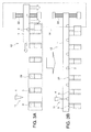
FIGS. 3A and 3B are a schematic longitudinal sectional view and a schematic plan view of essential parts of a manufacturing device for cleft magnets according to a second embodiment of this invention, -
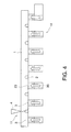
FIG. 4 is a schematic longitudinal sectional view of essential parts of a manufacturing device for cleft magnets according to a third embodiment of this invention, and -
FIG. 5 is similar toFIG. 4 , but showing a situation where air suction pipes are further applied. - The embodiments of this invention will be described with reference to the accompanying drawings.
- Referring to
FIG. 1 of the drawings, amanufacturing device 10 for cleft magnets according to a first embodiment of this invention comprises acleaving mechanism 11 for cleaving amagnet plate 1, a carry-inmechanism 12 for carrying themagnet plate 1 into thecleaving mechanism 11, a foreignmatter removal mechanism 14 for removing a foreign matter adhering to themagnet plate 1 prior to cleaving, and a carry-out mechanism 13 for carrying out cleft pieces of themagnet plate 1. Themagnet plate 1 is formed by solidifying magnetic particles into a plate-like body by pressure molding and sintering.Grooves 2 are formed at regular intervals on one surface of themagnet plate 1. - Referring to
FIG. 2 , thecleaving mechanism 11 comprises a pair ofdies 3 for supporting themagnet plate 1 from below, ablade 4 for pressing the back of thegroove 2 of themagnet plate 1 from above and astopper 26 for positioning themagnet plate 1 carried by the carry-inmechanism 12 at a predetermined cleaving position. The predetermined cleaving position is a position where thegroove 2 is located in the center between the pair ofdies 3. Themagnet plate 1 is successively cleft by thecleaving mechanism 11 for each of blocks partitioned by thegrooves 2. - The carry-in
mechanism 12 comprises a plurality ofsupports 23 for supporting themagnet plate 1 from below, aslider 21 to be displaced along arail 25 and aguide 24 for guiding themagnet plate 1 on thesupport 23 pressed by theslider 21 toward thecleaving mechanism 11. - The plurality of
supports 23 are arranged in a row withgaps 22 extending in a direction perpendicular to a sliding direction of themagnet plate 1. A surface of eachsupport 23 to be held in contact with themagnet plate 1 is formed to have a substantially triangular cross-section as shown inFIG. 1 . This causes eachsupport 23 to come into line contact with themagnet plate 1 and reduces frictional resistance against a sliding movement of themagnet plate 1. - Referring again to
FIG. 2 , theslider 21 displaces along therail 25 and presses the rear end of themagnet plate 1 on thesupports 23, thereby sliding themagnet plate 1 toward thecleaving mechanism 11 by a distance corresponding to the interval of thegrooves 2 inside theguide 24. It should be noted that themagnet plate 1 is placed on thesupports 23 in advance with thegrooves 2 faced down. - As described above, the
magnet plate 1 is successively cleft by thecleaving mechanism 11 for each of the blocks partitioned by thegrooves 2. Theslider 21 slides themagnet plate 1 toward thecleaving mechanism 11 every time thecleaving mechanism 11 performs cleaving. It should be noted that acleft piece 1A is carried out by the carry-out mechanism 13. - The foreign
matter removal mechanism 14 functions to remove foreign matters such as pieces of broken magnet and contamination substances adhering to themagnet plate 1 carried into thecleaving mechanism 11 by the carry-inmechanism 12. - In forming the
grooves 2 on themagnet plate 1, burrs may be formed on both sides of thegrooves 2. These burrs are removed in advance, but pieces of broken burr removed at that time may adhere to themagnet plate 1. Further, when thecleaving mechanism 11 cleaves themagnet plate 1, pieces of broken magnet may be produced and these may also adhere to themagnet plate 1. Foreign matters adhering to themagnet plate 1 in this way may be caught between thedies 3 and themagnet plate 1 when theslider 21 slides themagnet plate 1 toward thecleaving mechanism 11 to cleave the next block. - If a foreign matter is caught between the
die 3 and themagnet plate 1, a bending moment is applied to themagnet plate 1 when theblade 4 cleaves themagnet plate 1, resulting in causing abnormal breakage in themagnet plate 1. - In this embodiment, the foreign
matter removal mechanism 14 removes foreign matters adhering to themagnet plate 1 prior to the cleaving of themagnet plate 1 to prevent abnormal breakage. - Referring again to
FIG. 1 , the foreignmatter removal mechanism 14 is configured by adust collector 31 and ablower 32. - The
dust collector 31 collects foreign matters adhering to the lower surface of themagnet plate 1 located on thesupports 23 and those adhering to thegrooves 2 by sucking them via thegaps 22. Since a plurality ofgaps 22 are present at regular intervals, thedust collector 31 can apply a suction force over a wide range of the lower surface of themagnet plate 1. It should be noted that when themagnet plate 1 is positioned at a position, where themagnet plate 1 is cleft by theblade 4, by thestopper 26, thegrooves 2 other than thegroove 2 located at the cleaving position by theblade 4 are set at positions corresponding to thegaps 22, i.e. positions right above thegaps 22. Further, since upper parts of thesupports 23 are formed to have a substantially triangular cross-section as described above and held in line contact with themagnet plate 1, thedust collector 31 can remove the foreign matters on the entire lower surface of themagnet plate 1 including thegrooves 2 without being obstructed by thesupports 23. Furthermore, foreign matters adhering to thesupports 23 are also removed by thedust collector 31. - On the other hand, the
blower 32 is sandwiched between the rear end of themagnet plate 1 and theslider 21 and slides integrally with themagnet plate 1 toward thecleaving mechanism 11. Theblower 32 blows air toward thesupports 23 from the rear end of themagnet plate 1, thereby causing foreign matters remaining on thesupports 23 to fall to a side below thecarrying device 12 via thegaps 22. - Since the
magnet plate 1 is carried onto thedies 3 after the foreign matters are removed in this way, no foreign matter is caught between themagnet plate 1 and thedies 3 and abnormal breakage caused in themagnet plate 1 by the presence of a foreign matter can be prevented in a cleaving process of themagnet plate 1 by theblade 4. Accordingly, themanufacturing device 10 for cleft magnets cleaves themagnet plate 1 at thegrooves 2 with high cleaving accuracy. Thus, thecleft pieces 1A with good quality and small dimensional variation can be obtained as a result of cleaving. - In this embodiment, the
blower 32 is not an essential element of the foreignmatter removal mechanism 14. It is also possible to configure the foreignmatter removal mechanism 14 only by thedust collector 31. - Referring to
FIGS. 3A and 3B , a second embodiment of this invention concerning the foreignmatter removal mechanism 14 will be described. It should be noted that a sliding direction of themagnet plate 1 by the carry-inmechanism 12 inFIGS. 3A and 3B is opposite to that shown inFIGS. 1 and2 . - The foreign
matter removal mechanism 14 according to this embodiment comprises abrush 33 instead of thedust collector 31 and theblower 32 of the first embodiment. Thebrush 33 scrapes off foreign matters such as pieces of broken magnet and contamination substances adhering to themagnet plate 1 by bringing bristle ends into contact with themagnet plate 1 sliding toward thecleaving mechanism 11. - It should be noted that the
brush 33 could also be an air brush. - By removing the foreign matters from the
magnet plate 1 by thebrush 33 in this way, abnormal breakage of themagnet plate 1 resulting from a foreign matter caught in the cleaving process can be prevented as in the first embodiment. According to this embodiment, the foreignmatter removal mechanism 14 can be inexpensively realized by a simple configuration. Since thedust collector 31 is not used in this embodiment, thesupports 23 may not be formed to have a triangular cross-section unlike in the first embodiment. - Referring to
FIGS. 4 and5 , a third embodiment of this invention concerning the foreignmatter removal mechanism 14 will described. - The foreign
matter removal mechanism 14 according to this embodiment comprises a plurality of air supply holes 35 and a plurality ofair suction ports 36 instead of thedust collector 31 and theblower 32 of the first embodiment. - Referring to
FIG. 4 , the air supply holes 35 are formed to vertically penetrate eachsupport 23 and each die 3. The air supply holes 35 are connected to a compressor not shown. Blowout ports for blowing air around from the air supply holes 35 are formed at the upper ends of eachsupport 23 and each die 3. Foreign matters such as pieces of broken magnet and contamination substances adhering to the lower surface of themagnet plate 1 are blown off by the air blown out from the blowout ports. - Referring to
FIG. 5 , theair suction ports 36 are formed inair suction pipes 34. Theair suction pipes 34 face thegrooves 2 of themagnet plate 1 supported on thesupports 23 from below. Theair suction ports 36 are connected to a suction device not shown. Theair suction pipes 34 suck the air blown out from the air supply holes 35 located on both sides together with foreign matters removed from themagnet plate 1 by the air blown out from the air supply holes 35. By the above configuration, the foreignmatter removal mechanism 14 removes the foreign matters from themagnet plate 1 before thecleaving mechanism 11 cleaves themagnet plate 1. - Accordingly, abnormal breakage of the
magnet plate 1 resulting from a foreign matter caught in the cleaving process can be prevented as in the first embodiment. - It should be noted that the
air suction pipes 34 are not an essential element of the foreignmatter removal mechanism 14 in this embodiment. Theair suction pipes 34 have a preferable effect in preventing the scattering of foreign matters, but an action of removing foreign matters from themagnet plate 1 can also be achieved only by the air supply holes 35. Since the air supply holes 35 are formed in constituent members of the carry-inmechanism 12 and thecleaving mechanism 13 such as thesupports 23 and the dies 3, dedicated members for forming the air supply holes 35 are not necessary. - It is also preferable that the
air suction pipes 34 are configured to be movable between a suction position shown inFIG. 5 and a retracted position so as to move to the suction position only when a foreign matter removal process is performed and retract to the retracted position when other processes are performed. Theair suction ports 36 may be provided in thesupports 23 and the dies 3 and the air supply holes 35 may be provided between thesupports 23. - As described above, the
manufacturing device 10 for cleft magnets according to this invention comprises the foreignmatter removal mechanism 14 for removing foreign matters from themagnet plate 1 before themagnet plate 1 is cleft by thecleaving mechanism 11. The foreignmatter removal mechanism 14 prevents a foreign matter from being caught between themagnet plate 1 and thedie 3 when themagnet plate 1 is cleft by thecleaving mechanism 11. Thus, abnormal breakage of themagnet plate 1 caused by the foreign matter caught between themagnet plate 1 and thedie 3 can be prevented. As a result, themagnet plate 1 is reliably cleft at thegrooves 2 and accuracy in cleaving themagnet plate 1 can be enhanced. This brings about a preferable effect in improving the quality of a permanent magnet. - The foreign
matter removal mechanism 14 may be constituted by thedust collector 31 for sucking air via thegaps 22 between the plurality ofsupports 23 as shown in the first embodiment. In this case, a foreign matter removal range can be widened by forming contact parts of thesupports 23 with themagnet plate 1 to have a substantially triangular cross-section. Further, foreign matters on thesupports 23 can also be removed by providing the carry-inmechanism 12 with theblower 32 facing thegroove 2 from above. - If the foreign
matter removal mechanism 14 is constituted by thebrush 33 as shown in the second embodiment, it can be inexpensively realized by a simple configuration. - The foreign
matter removal mechanism 14 may be configured by the air supply holes 35 vertically penetrating thesupports 23 and the dies 3 as shown in the third embodiment. In this case, it is not necessary to provide dedicated members for forming the air supply holes 35 and the foreignmatter removal mechanism 14 can be installed in a space-efficient manner. It should be noted that the air supply holes 35 could also be formed only in thesupports 23 or only in the dies 3. Further, foreign matters can be reliably collected by providing theair suction ports 36 in addition to the air supply holes 35 as the foreignmatter removal mechanism 14. - As described above, the foreign
matter removal mechanism 14 removes foreign matters such as pieces of broken magnet and contamination substances adhering to themagnet plate 1 before themagnet plate 1 is carried to the cleaving position by the carry-inmechanism 12. This prevents foreign matters from being caught between themagnet plate 1 and thecleaving mechanism 11 when themagnet plate 1 is cleft by thecleaving mechanism 11. As a result, abnormal breakage of themagnet plate 1 is less likely to occur and accuracy in cleaving themagnet plate 1 can be enhanced. - Although the embodiments of this invention have been described above, the above embodiments are merely some application examples of this invention and not of the nature to limit the technical scope of this invention to the specific configurations of the above embodiments.
- The contents of
Tokugan 2012-208366, with a filing date of September 21, 2012
Claims (8)
- A manufacturing device for cleft magnets, comprising:a cleaving mechanism for cleaving a magnet plate having a groove on one surface by applying a pressing force onto another surface of the magnet plate corresponding to a back of the groove;a carry-in mechanism for carrying the magnet plate to a cleaving position by the cleaving mechanism, anda foreign matter removal mechanism for removing a foreign matter adhering to the magnet plate before the magnet plate is carried to the cleaving position by the carry-in mechanism.
- The manufacturing device for cleft magnets according to Claim 1, wherein the carry-in mechanism comprises a plurality of supports for supporting the magnet plate carried to the cleaving position in an upward facing posture, and the foreign matter removal mechanism comprises a dust collector for applying a suction force to a gap between the plurality of supports.
- The manufacturing device for cleft magnets according to Claim 2, wherein contact parts of the plurality of supports with the magnet plate are formed to have a substantially triangular cross-section.
- The manufacturing device for cleft magnets according to any one of Claims 1 to 3, wherein the carry-in mechanism comprises a blower for blowing air into the gap between the supports after a passage of the magnet plate.
- The manufacturing device for cleft magnets according to Claim 1, wherein the foreign matter removal mechanism comprises a brush to be held in contact with the magnet plate.
- The manufacturing device for cleft magnets according to Claim 1, wherein the foreign matter removal mechanism comprises air supply holes respectively formed to vertically penetrate a plurality of supports and blowout ports respectively formed in the plurality of supports for blowing air supplied from the air supply holes to the magnet plate.
- The manufacturing device for cleft magnets according to Claim 6, wherein the foreign matter removal mechanism further comprises an air suction pipe arranged between the plurality of supports and configured to suck the air blown to the magnet plate.
- The manufacturing device for cleft magnets according to Claim 6 or 7, wherein the cleaving mechanism comprises a pair of dies for supporting the magnet plate on both sides of the groove and a blade for pressing the magnet plate at a location corresponding to the back of the groove, and the air supply holes and the blowout ports are respectively provided in the pair of dies.
Applications Claiming Priority (2)
| Application Number | Priority Date | Filing Date | Title |
|---|---|---|---|
| JP2012208366 | 2012-09-21 | ||
| PCT/JP2013/075318 WO2014046189A1 (en) | 2012-09-21 | 2013-09-19 | Device for producing cracking magnet |
Publications (3)
| Publication Number | Publication Date |
|---|---|
| EP2899859A1 true EP2899859A1 (en) | 2015-07-29 |
| EP2899859A4 EP2899859A4 (en) | 2015-09-23 |
| EP2899859B1 EP2899859B1 (en) | 2016-11-09 |
Family
ID=50341493
Family Applications (1)
| Application Number | Title | Priority Date | Filing Date |
|---|---|---|---|
| EP13838389.8A Active EP2899859B1 (en) | 2012-09-21 | 2013-09-19 | Manufacturing device for cleft magnets |
Country Status (5)
| Country | Link |
|---|---|
| US (1) | US9779871B2 (en) |
| EP (1) | EP2899859B1 (en) |
| JP (1) | JP5935895B2 (en) |
| CN (1) | CN104662782B (en) |
| WO (1) | WO2014046189A1 (en) |
Families Citing this family (3)
| Publication number | Priority date | Publication date | Assignee | Title |
|---|---|---|---|---|
| JP5929153B2 (en) * | 2011-12-14 | 2016-06-01 | 日産自動車株式会社 | Field pole magnet body manufacturing apparatus and method |
| CN106558953B (en) * | 2016-11-02 | 2019-05-14 | 浙江露通机电有限公司 | A multi-directional magnetic steel sheet automatic export device |
| CN113346685B (en) * | 2020-05-25 | 2022-10-18 | 阳江核电有限公司 | Method for removing flaky flexible foreign matters in nuclear power generator rotor |
Family Cites Families (13)
| Publication number | Priority date | Publication date | Assignee | Title |
|---|---|---|---|---|
| US3944203A (en) * | 1973-11-30 | 1976-03-16 | Brekelbaum Erwin C | Oxidation cutting work support means |
| JPS5157283A (en) * | 1974-11-15 | 1976-05-19 | Nippon Electric Co | Handotaikibanno bunkatsuhoho |
| JP3172521B1 (en) * | 2000-06-29 | 2001-06-04 | 住友特殊金属株式会社 | Rare earth magnet manufacturing method and powder pressing device |
| JP2002035984A (en) * | 2000-07-27 | 2002-02-05 | Nec Oita Ltd | Laser imprinting device |
| US6497403B2 (en) * | 2000-12-28 | 2002-12-24 | Memc Electronic Materials, Inc. | Semiconductor wafer holder |
| KR100724474B1 (en) * | 2002-10-22 | 2007-06-04 | 엘지.필립스 엘시디 주식회사 | Device for cutting liquid crystal display panel and method for cutting the same |
| WO2007134627A1 (en) * | 2006-05-24 | 2007-11-29 | Trumpf Werkzeugmaschinen Gmbh + Co. Kg | Work rest for accommodating an, in particular tabular, workpiece in a machining unit, with supporting elements which can be attached to rest elements |
| DE102007043567B3 (en) * | 2007-09-13 | 2008-10-02 | Grenzebach Maschinenbau Gmbh | Method for removing a region of a glass strip continuously produced on a conveyor belt used during the production of float glass comprises scribing a line marking the removal of the glass strip |
| JP4497198B2 (en) | 2007-12-06 | 2010-07-07 | トヨタ自動車株式会社 | Permanent magnet and method for manufacturing the same, and rotor and IPM motor |
| JP5515250B2 (en) * | 2008-07-31 | 2014-06-11 | 富士通株式会社 | Dust collecting mechanism and substrate cutting device |
| JP5267671B2 (en) * | 2009-07-29 | 2013-08-21 | トヨタ自動車株式会社 | Magnet handling equipment |
| JP5614096B2 (en) | 2010-05-19 | 2014-10-29 | 日産自動車株式会社 | Permanent magnet embedded in rotor core of rotating electrical machine and method for manufacturing the same |
| EP2738922B1 (en) * | 2011-07-27 | 2020-03-25 | Nissan Motor Co., Ltd | Device for producing field-pole magnet and method for producing same |
-
2013
- 2013-09-19 EP EP13838389.8A patent/EP2899859B1/en active Active
- 2013-09-19 CN CN201380048969.XA patent/CN104662782B/en active Active
- 2013-09-19 US US14/429,918 patent/US9779871B2/en active Active
- 2013-09-19 WO PCT/JP2013/075318 patent/WO2014046189A1/en not_active Ceased
- 2013-09-19 JP JP2014536909A patent/JP5935895B2/en active Active
Also Published As
| Publication number | Publication date |
|---|---|
| US20150270060A1 (en) | 2015-09-24 |
| EP2899859A4 (en) | 2015-09-23 |
| US9779871B2 (en) | 2017-10-03 |
| CN104662782B (en) | 2016-10-12 |
| WO2014046189A1 (en) | 2014-03-27 |
| JP5935895B2 (en) | 2016-06-15 |
| JPWO2014046189A1 (en) | 2016-08-18 |
| EP2899859B1 (en) | 2016-11-09 |
| CN104662782A (en) | 2015-05-27 |
Similar Documents
| Publication | Publication Date | Title |
|---|---|---|
| KR101323675B1 (en) | Breaking apparatus | |
| WO2023005131A1 (en) | Process for processing silicon steel sheet for disc motor | |
| JP5796774B2 (en) | Cleaving method and apparatus for brittle plate | |
| US9779871B2 (en) | Manufacturing device for cleft magnet | |
| CN103650304B (en) | The manufacturing installation of excitation pole magnet and manufacture method thereof | |
| KR20140011469A (en) | Breaking apparatus for brittle material substrate | |
| JP2004167513A (en) | Pipe drilling device and method for producing drilled pipe | |
| EP3041114B1 (en) | Cutting method and cutting device for manufacturing magnet piece constituting magnet body for field pole to be arranged in rotary electric machine | |
| CN104283089A (en) | Novel wire stripping machine for LED lamp | |
| EP3057207B1 (en) | Method and device for manufacturing magnet pieces configuring a field pole magnet to be arranged in a rotary machine | |
| CN105264754B (en) | Magnet chopping up apparatus | |
| TWI490151B (en) | Carrying device | |
| CN107186046B (en) | Cut-off dies for square tubes for guardrails or fences | |
| CN219535156U (en) | Wire passing assembly and wire part paint removing device with same | |
| JP5881589B2 (en) | Lead processing equipment | |
| JP6059055B2 (en) | Cleaving method of permanent magnet | |
| JP2019115937A (en) | Workpiece processing device | |
| CN110937384A (en) | Material pushing device | |
| KR20210100596A (en) | Method for manufacturing a glass plate | |
| CN104998953A (en) | Trimming mold for machining movable pole plate connecting piece of electrostatic precipitator | |
| CN102172114A (en) | Device and method for positioning electronic components in a processing tool |
Legal Events
| Date | Code | Title | Description |
|---|---|---|---|
| PUAI | Public reference made under article 153(3) epc to a published international application that has entered the european phase |
Free format text: ORIGINAL CODE: 0009012 |
|
| 17P | Request for examination filed |
Effective date: 20150421 |
|
| AK | Designated contracting states |
Kind code of ref document: A1 Designated state(s): AL AT BE BG CH CY CZ DE DK EE ES FI FR GB GR HR HU IE IS IT LI LT LU LV MC MK MT NL NO PL PT RO RS SE SI SK SM TR |
|
| AX | Request for extension of the european patent |
Extension state: BA ME |
|
| RA4 | Supplementary search report drawn up and despatched (corrected) |
Effective date: 20150824 |
|
| RIC1 | Information provided on ipc code assigned before grant |
Ipc: B26F 3/00 20060101ALI20150818BHEP Ipc: H02K 15/03 20060101AFI20150818BHEP |
|
| DAX | Request for extension of the european patent (deleted) | ||
| REG | Reference to a national code |
Ref country code: DE Ref legal event code: R079 Ref document number: 602013013979 Country of ref document: DE Free format text: PREVIOUS MAIN CLASS: H02K0015030000 Ipc: H01F0041020000 |
|
| GRAP | Despatch of communication of intention to grant a patent |
Free format text: ORIGINAL CODE: EPIDOSNIGR1 |
|
| RIC1 | Information provided on ipc code assigned before grant |
Ipc: B26F 3/00 20060101ALI20160601BHEP Ipc: H02K 15/03 20060101ALI20160601BHEP Ipc: H01F 41/02 20060101AFI20160601BHEP |
|
| INTG | Intention to grant announced |
Effective date: 20160701 |
|
| GRAS | Grant fee paid |
Free format text: ORIGINAL CODE: EPIDOSNIGR3 |
|
| GRAA | (expected) grant |
Free format text: ORIGINAL CODE: 0009210 |
|
| AK | Designated contracting states |
Kind code of ref document: B1 Designated state(s): AL AT BE BG CH CY CZ DE DK EE ES FI FR GB GR HR HU IE IS IT LI LT LU LV MC MK MT NL NO PL PT RO RS SE SI SK SM TR |
|
| REG | Reference to a national code |
Ref country code: GB Ref legal event code: FG4D |
|
| REG | Reference to a national code |
Ref country code: AT Ref legal event code: REF Ref document number: 844611 Country of ref document: AT Kind code of ref document: T Effective date: 20161115 Ref country code: CH Ref legal event code: EP |
|
| REG | Reference to a national code |
Ref country code: IE Ref legal event code: FG4D |
|
| REG | Reference to a national code |
Ref country code: DE Ref legal event code: R096 Ref document number: 602013013979 Country of ref document: DE |
|
| PG25 | Lapsed in a contracting state [announced via postgrant information from national office to epo] |
Ref country code: LV Free format text: LAPSE BECAUSE OF FAILURE TO SUBMIT A TRANSLATION OF THE DESCRIPTION OR TO PAY THE FEE WITHIN THE PRESCRIBED TIME-LIMIT Effective date: 20161109 |
|
| REG | Reference to a national code |
Ref country code: LT Ref legal event code: MG4D |
|
| REG | Reference to a national code |
Ref country code: NL Ref legal event code: MP Effective date: 20161109 |
|
| REG | Reference to a national code |
Ref country code: AT Ref legal event code: MK05 Ref document number: 844611 Country of ref document: AT Kind code of ref document: T Effective date: 20161109 |
|
| PG25 | Lapsed in a contracting state [announced via postgrant information from national office to epo] |
Ref country code: NL Free format text: LAPSE BECAUSE OF FAILURE TO SUBMIT A TRANSLATION OF THE DESCRIPTION OR TO PAY THE FEE WITHIN THE PRESCRIBED TIME-LIMIT Effective date: 20161109 Ref country code: LT Free format text: LAPSE BECAUSE OF FAILURE TO SUBMIT A TRANSLATION OF THE DESCRIPTION OR TO PAY THE FEE WITHIN THE PRESCRIBED TIME-LIMIT Effective date: 20161109 Ref country code: SE Free format text: LAPSE BECAUSE OF FAILURE TO SUBMIT A TRANSLATION OF THE DESCRIPTION OR TO PAY THE FEE WITHIN THE PRESCRIBED TIME-LIMIT Effective date: 20161109 Ref country code: NO Free format text: LAPSE BECAUSE OF FAILURE TO SUBMIT A TRANSLATION OF THE DESCRIPTION OR TO PAY THE FEE WITHIN THE PRESCRIBED TIME-LIMIT Effective date: 20170209 Ref country code: GR Free format text: LAPSE BECAUSE OF FAILURE TO SUBMIT A TRANSLATION OF THE DESCRIPTION OR TO PAY THE FEE WITHIN THE PRESCRIBED TIME-LIMIT Effective date: 20170210 |
|
| PG25 | Lapsed in a contracting state [announced via postgrant information from national office to epo] |
Ref country code: ES Free format text: LAPSE BECAUSE OF FAILURE TO SUBMIT A TRANSLATION OF THE DESCRIPTION OR TO PAY THE FEE WITHIN THE PRESCRIBED TIME-LIMIT Effective date: 20161109 Ref country code: AT Free format text: LAPSE BECAUSE OF FAILURE TO SUBMIT A TRANSLATION OF THE DESCRIPTION OR TO PAY THE FEE WITHIN THE PRESCRIBED TIME-LIMIT Effective date: 20161109 Ref country code: PL Free format text: LAPSE BECAUSE OF FAILURE TO SUBMIT A TRANSLATION OF THE DESCRIPTION OR TO PAY THE FEE WITHIN THE PRESCRIBED TIME-LIMIT Effective date: 20161109 Ref country code: IS Free format text: LAPSE BECAUSE OF FAILURE TO SUBMIT A TRANSLATION OF THE DESCRIPTION OR TO PAY THE FEE WITHIN THE PRESCRIBED TIME-LIMIT Effective date: 20170309 Ref country code: PT Free format text: LAPSE BECAUSE OF FAILURE TO SUBMIT A TRANSLATION OF THE DESCRIPTION OR TO PAY THE FEE WITHIN THE PRESCRIBED TIME-LIMIT Effective date: 20170309 Ref country code: RS Free format text: LAPSE BECAUSE OF FAILURE TO SUBMIT A TRANSLATION OF THE DESCRIPTION OR TO PAY THE FEE WITHIN THE PRESCRIBED TIME-LIMIT Effective date: 20161109 Ref country code: FI Free format text: LAPSE BECAUSE OF FAILURE TO SUBMIT A TRANSLATION OF THE DESCRIPTION OR TO PAY THE FEE WITHIN THE PRESCRIBED TIME-LIMIT Effective date: 20161109 Ref country code: HR Free format text: LAPSE BECAUSE OF FAILURE TO SUBMIT A TRANSLATION OF THE DESCRIPTION OR TO PAY THE FEE WITHIN THE PRESCRIBED TIME-LIMIT Effective date: 20161109 |
|
| PG25 | Lapsed in a contracting state [announced via postgrant information from national office to epo] |
Ref country code: DK Free format text: LAPSE BECAUSE OF FAILURE TO SUBMIT A TRANSLATION OF THE DESCRIPTION OR TO PAY THE FEE WITHIN THE PRESCRIBED TIME-LIMIT Effective date: 20161109 Ref country code: SK Free format text: LAPSE BECAUSE OF FAILURE TO SUBMIT A TRANSLATION OF THE DESCRIPTION OR TO PAY THE FEE WITHIN THE PRESCRIBED TIME-LIMIT Effective date: 20161109 Ref country code: RO Free format text: LAPSE BECAUSE OF FAILURE TO SUBMIT A TRANSLATION OF THE DESCRIPTION OR TO PAY THE FEE WITHIN THE PRESCRIBED TIME-LIMIT Effective date: 20161109 Ref country code: CZ Free format text: LAPSE BECAUSE OF FAILURE TO SUBMIT A TRANSLATION OF THE DESCRIPTION OR TO PAY THE FEE WITHIN THE PRESCRIBED TIME-LIMIT Effective date: 20161109 Ref country code: EE Free format text: LAPSE BECAUSE OF FAILURE TO SUBMIT A TRANSLATION OF THE DESCRIPTION OR TO PAY THE FEE WITHIN THE PRESCRIBED TIME-LIMIT Effective date: 20161109 |
|
| REG | Reference to a national code |
Ref country code: FR Ref legal event code: PLFP Year of fee payment: 5 Ref country code: DE Ref legal event code: R097 Ref document number: 602013013979 Country of ref document: DE |
|
| PG25 | Lapsed in a contracting state [announced via postgrant information from national office to epo] |
Ref country code: SM Free format text: LAPSE BECAUSE OF FAILURE TO SUBMIT A TRANSLATION OF THE DESCRIPTION OR TO PAY THE FEE WITHIN THE PRESCRIBED TIME-LIMIT Effective date: 20161109 Ref country code: IT Free format text: LAPSE BECAUSE OF FAILURE TO SUBMIT A TRANSLATION OF THE DESCRIPTION OR TO PAY THE FEE WITHIN THE PRESCRIBED TIME-LIMIT Effective date: 20161109 Ref country code: BE Free format text: LAPSE BECAUSE OF FAILURE TO SUBMIT A TRANSLATION OF THE DESCRIPTION OR TO PAY THE FEE WITHIN THE PRESCRIBED TIME-LIMIT Effective date: 20161109 Ref country code: BG Free format text: LAPSE BECAUSE OF FAILURE TO SUBMIT A TRANSLATION OF THE DESCRIPTION OR TO PAY THE FEE WITHIN THE PRESCRIBED TIME-LIMIT Effective date: 20170209 |
|
| PLBE | No opposition filed within time limit |
Free format text: ORIGINAL CODE: 0009261 |
|
| STAA | Information on the status of an ep patent application or granted ep patent |
Free format text: STATUS: NO OPPOSITION FILED WITHIN TIME LIMIT |
|
| 26N | No opposition filed |
Effective date: 20170810 |
|
| PG25 | Lapsed in a contracting state [announced via postgrant information from national office to epo] |
Ref country code: SI Free format text: LAPSE BECAUSE OF FAILURE TO SUBMIT A TRANSLATION OF THE DESCRIPTION OR TO PAY THE FEE WITHIN THE PRESCRIBED TIME-LIMIT Effective date: 20161109 |
|
| REG | Reference to a national code |
Ref country code: CH Ref legal event code: PL |
|
| PG25 | Lapsed in a contracting state [announced via postgrant information from national office to epo] |
Ref country code: MC Free format text: LAPSE BECAUSE OF FAILURE TO SUBMIT A TRANSLATION OF THE DESCRIPTION OR TO PAY THE FEE WITHIN THE PRESCRIBED TIME-LIMIT Effective date: 20161109 |
|
| REG | Reference to a national code |
Ref country code: IE Ref legal event code: MM4A |
|
| PG25 | Lapsed in a contracting state [announced via postgrant information from national office to epo] |
Ref country code: LU Free format text: LAPSE BECAUSE OF NON-PAYMENT OF DUE FEES Effective date: 20170919 |
|
| PG25 | Lapsed in a contracting state [announced via postgrant information from national office to epo] |
Ref country code: CH Free format text: LAPSE BECAUSE OF NON-PAYMENT OF DUE FEES Effective date: 20170930 Ref country code: LI Free format text: LAPSE BECAUSE OF NON-PAYMENT OF DUE FEES Effective date: 20170930 Ref country code: IE Free format text: LAPSE BECAUSE OF NON-PAYMENT OF DUE FEES Effective date: 20170919 |
|
| REG | Reference to a national code |
Ref country code: FR Ref legal event code: PLFP Year of fee payment: 6 |
|
| PG25 | Lapsed in a contracting state [announced via postgrant information from national office to epo] |
Ref country code: MT Free format text: LAPSE BECAUSE OF NON-PAYMENT OF DUE FEES Effective date: 20170919 |
|
| PG25 | Lapsed in a contracting state [announced via postgrant information from national office to epo] |
Ref country code: HU Free format text: LAPSE BECAUSE OF FAILURE TO SUBMIT A TRANSLATION OF THE DESCRIPTION OR TO PAY THE FEE WITHIN THE PRESCRIBED TIME-LIMIT; INVALID AB INITIO Effective date: 20130919 |
|
| PG25 | Lapsed in a contracting state [announced via postgrant information from national office to epo] |
Ref country code: CY Free format text: LAPSE BECAUSE OF FAILURE TO SUBMIT A TRANSLATION OF THE DESCRIPTION OR TO PAY THE FEE WITHIN THE PRESCRIBED TIME-LIMIT Effective date: 20161109 |
|
| PG25 | Lapsed in a contracting state [announced via postgrant information from national office to epo] |
Ref country code: MK Free format text: LAPSE BECAUSE OF FAILURE TO SUBMIT A TRANSLATION OF THE DESCRIPTION OR TO PAY THE FEE WITHIN THE PRESCRIBED TIME-LIMIT Effective date: 20161109 |
|
| PG25 | Lapsed in a contracting state [announced via postgrant information from national office to epo] |
Ref country code: TR Free format text: LAPSE BECAUSE OF FAILURE TO SUBMIT A TRANSLATION OF THE DESCRIPTION OR TO PAY THE FEE WITHIN THE PRESCRIBED TIME-LIMIT Effective date: 20161109 |
|
| PG25 | Lapsed in a contracting state [announced via postgrant information from national office to epo] |
Ref country code: AL Free format text: LAPSE BECAUSE OF FAILURE TO SUBMIT A TRANSLATION OF THE DESCRIPTION OR TO PAY THE FEE WITHIN THE PRESCRIBED TIME-LIMIT Effective date: 20161109 |
|
| PGFP | Annual fee paid to national office [announced via postgrant information from national office to epo] |
Ref country code: DE Payment date: 20250820 Year of fee payment: 13 |
|
| PGFP | Annual fee paid to national office [announced via postgrant information from national office to epo] |
Ref country code: GB Payment date: 20250822 Year of fee payment: 13 |
|
| PGFP | Annual fee paid to national office [announced via postgrant information from national office to epo] |
Ref country code: FR Payment date: 20250820 Year of fee payment: 13 |