EP2899560A1 - Magnetic field sensor and method used in a magnetic field sensor that adjusts a sensitivity and/or an offset over temperature - Google Patents
Magnetic field sensor and method used in a magnetic field sensor that adjusts a sensitivity and/or an offset over temperature Download PDFInfo
- Publication number
- EP2899560A1 EP2899560A1 EP15156091.9A EP15156091A EP2899560A1 EP 2899560 A1 EP2899560 A1 EP 2899560A1 EP 15156091 A EP15156091 A EP 15156091A EP 2899560 A1 EP2899560 A1 EP 2899560A1
- Authority
- EP
- European Patent Office
- Prior art keywords
- magnetic field
- offset
- field sensor
- correction value
- temperature
- Prior art date
- Legal status (The legal status is an assumption and is not a legal conclusion. Google has not performed a legal analysis and makes no representation as to the accuracy of the status listed.)
- Granted
Links
Images



Classifications
-
- G—PHYSICS
- G01—MEASURING; TESTING
- G01R—MEASURING ELECTRIC VARIABLES; MEASURING MAGNETIC VARIABLES
- G01R33/00—Arrangements or instruments for measuring magnetic variables
- G01R33/02—Measuring direction or magnitude of magnetic fields or magnetic flux
-
- G—PHYSICS
- G01—MEASURING; TESTING
- G01R—MEASURING ELECTRIC VARIABLES; MEASURING MAGNETIC VARIABLES
- G01R33/00—Arrangements or instruments for measuring magnetic variables
- G01R33/0023—Electronic aspects, e.g. circuits for stimulation, evaluation, control; Treating the measured signals; calibration
- G01R33/0029—Treating the measured signals, e.g. removing offset or noise
-
- G—PHYSICS
- G01—MEASURING; TESTING
- G01R—MEASURING ELECTRIC VARIABLES; MEASURING MAGNETIC VARIABLES
- G01R33/00—Arrangements or instruments for measuring magnetic variables
- G01R33/0023—Electronic aspects, e.g. circuits for stimulation, evaluation, control; Treating the measured signals; calibration
- G01R33/0041—Electronic aspects, e.g. circuits for stimulation, evaluation, control; Treating the measured signals; calibration using feed-back or modulation techniques
-
- G—PHYSICS
- G01—MEASURING; TESTING
- G01R—MEASURING ELECTRIC VARIABLES; MEASURING MAGNETIC VARIABLES
- G01R33/00—Arrangements or instruments for measuring magnetic variables
- G01R33/02—Measuring direction or magnitude of magnetic fields or magnetic flux
- G01R33/06—Measuring direction or magnitude of magnetic fields or magnetic flux using galvano-magnetic devices
- G01R33/07—Hall effect devices
- G01R33/072—Constructional adaptation of the sensor to specific applications
Definitions
- This invention relates generally to magnetic field sensors and, more particularly, to a magnetic field sensor that can adjust a gain and/or an offset in response to a sensed temperature.
- a magnetic field sensor can be used to sense an electrical current.
- One type of current sensor uses a Hall effect magnetic field sensing element in proximity to a current-carrying conductor.
- the Hall effect magnetic field sensing element generates an output signal having a magnitude proportional to the magnetic field induced by the current through the conductor.
- Typical current sensors of this type include a gapped toroid magnetic flux concentrator, with the Hall effect device positioned in a toroid gap.
- the Hall effect device and toroid are assembled in a housing, which is mountable on a printed circuit board.
- a separate current-carrying conductor such as a wire, is passed through the center of the toroid and is soldered to the printed circuit board, such as by soldering exposed ends of the wire to plated through-holes.
- a sensitivity of a magnetic field sensor is a change in the output signal of the magnetic field sensor in proportion to a magnetic field experienced by the magnetic field sensor.
- an offset voltage is an unwanted DC offset voltage of an output signal from the magnetic field sensor, normally biased at the power supply of the magnetic field sensor divided by two, for example, five volts divided by two or 2.5 Volts.
- a linearity is the degree to which the output signal of a magnetic field sensor varies in direct linear proportion to the magnetic field (e.g., current) experienced by the magnetic field sensor.
- Sensitivity variation tends to be related to a stress and/or strain imparted on a magnetic field sensing element used in the magnetic field sensor, for example, upon a Hall effect element, as temperature changes, for example, due to expansion or contraction of packaging of the magnetic field sensor or of the substrate on which the magnetic field sensing element is disposed.
- Offset variation tends to be related to temperature variable characteristics of amplifiers used in the magnetic field sensor.
- Magnetic field sensors sometimes employ analog compensation techniques that can adjust gain (i.e., sensitivity) and/or offset with respect to temperature, for example, using varistors or the like. Such techniques can result in sensitivities and offsets that are fairly invariant with respect to temperature, but often at the expense of room temperature accuracy of sensitivity or offset. Furthermore, analog compensation techniques are fixed and not suited for production or field changes to the compensation.
- Magnetic field sensors with digital circuits tend to be slower than magnetic field sensors with analog circuits. In other words, magnetic field sensors with digital circuits cannot respond well to rapidly changing magnetic fields (e.g., due to rapidly changing currents).
- the present invention provides a magnetic field sensor with an analog signal path that is corrected for sensitivity and/or offset by digital circuits. This arrangement achieves the rapid response time of analog circuits, achieves sensitivity and/or offset accuracy, particularly at room temperature, and achieves production (or field) changeability without production perturbations.
- a magnetic field sensor includes a magnetic field sensing element configured to generate a magnetic field signal.
- the magnetic field sensor also includes a gain adjustable analog circuit coupled to receive a signal representative of the magnetic field signal, coupled to receive a gain control signal, and configured to generate a gain adjusted signal having a gain responsive to the gain control signal.
- the magnetic field sensor also includes a coefficient table memory configured to receive and store a plurality of gain correction coefficients. Pairs of the plurality of gain correction coefficients are associated with boundaries of respective temperature segments, each temperature segment bounded by a pair of temperatures.
- the magnetic field sensor also includes a temperature sensor configured to generate a temperature signal representative of a temperature.
- the magnetic field sensor also includes a segment processor coupled to receive a signal representative of the temperature signal, configured to identify a temperature segment in which the temperature signal falls, coupled to receive a pair of gain correction coefficients associated with the identified temperature segment, and configured to interpolate between the pair of gain correction coefficients in accordance with the temperature signal to generate an interpolated gain correction value, wherein the gain control signal is an analog signal related to the interpolated gain correction value.
- a segment processor coupled to receive a signal representative of the temperature signal, configured to identify a temperature segment in which the temperature signal falls, coupled to receive a pair of gain correction coefficients associated with the identified temperature segment, and configured to interpolate between the pair of gain correction coefficients in accordance with the temperature signal to generate an interpolated gain correction value, wherein the gain control signal is an analog signal related to the interpolated gain correction value.
- the magnetic field sensor also includes a user gain correction value register coupled to receive a user gain correction value
- the segment processor comprises a combining processor coupled to receive the user gain correction value, coupled to receive the interpolated gain correction value, and configured to combine the user gain correction value with the interpolated gain correction value to generate a combined gain correction value
- the gain control signal is an analog signal related to the combined gain correction value
- the magnetic field sensor also includes an offset adjustable analog circuit coupled to receive a signal representative of the magnetic field signal, coupled to receive an offset control signal, and configured to generate an offset adjusted signal having an offset responsive to the offset control signal, wherein the coefficient table memory is further configured to receive and store a plurality of offset correction coefficients, wherein pairs of the plurality of offset correction coefficients are associated with boundaries of respective temperature segments, wherein the segment processor is further coupled to receive a pair of offset correction coefficients associated with the identified temperature segment and configured to interpolate between the pair of offset correction coefficients in accordance with the temperature signal to generate an interpolated offset correction value, and wherein the offset control signal is an analog signal related to the interpolated offset correction value.
- an offset adjustable analog circuit coupled to receive a signal representative of the magnetic field signal, coupled to receive an offset control signal, and configured to generate an offset adjusted signal having an offset responsive to the offset control signal
- the coefficient table memory is further configured to receive and store a plurality of offset correction coefficients, wherein pairs of the plurality of offset correction coefficients are associated with boundaries
- the magnetic field sensor also includes a user gain correction value register coupled to receive a user gain correction value
- the segment processor comprises a combining processor coupled to receive the user gain correction value and coupled to receive the interpolated gain correction value and configured to combine the user gain correction value with the interpolated gain correction value to generate a combined gain correction value
- the gain control signal is an analog signal related to the combined gain correction value
- the magnetic field sensor also includes a user offset correction value register coupled to receive a user offset correction value, wherein the combining processor is further coupled to receive the user offset correction value and coupled to receive the interpolated offset correction value and further configured to combine the user offset correction value with the interpolated offset correction value to generate a combined offset correction value, wherein the offset control signal is an analog signal related to the combined offset correction value.
- the magnetic field sensor also includes a program control register coupled to receive a program control value, wherein the segment processor is coupled to receive a signal representative of the program control value, and, in response to the program control value, the segment processor is configured to select an interpolation type from among a plurality of predetermined interpolation types.
- a method of adjusting a magnetic field sensor includes measuring a temperature with the magnetic field sensor during field operation.
- the method also includes identifying with the magnetic field sensor in which one of a predetermined plurality of temperature segments the field measured temperature lies.
- the method also includes identifying with the magnetic field sensor a pair of predetermined calibration temperatures associated with boundaries of the identified temperature segment.
- the method also includes identifying with the magnetic field sensor a pair of gain calibration coefficients associated with the boundaries of the identified temperature segment, the pair of gain calibration coefficients stored within the magnetic field sensor.
- the method also includes interpolating with the magnetic field sensor between the pair of gain calibration coefficients to establish an interpolated gain correction value.
- the method also includes applying an analog signal related to the interpolated gain correction value to a gain adjustment circuit within the magnetic field sensor.
- the method also includes receiving a user gain correction value with the magnetic field sensor, combining with the magnetic field sensor the interpolated gain correction value and the user gain correction value to generate a combined gain correction value, and applying an analog signal related to the combined gain correction value to the gain adjustment circuit.
- the method also includes identifying with the magnetic field sensor a pair of offset calibration coefficients associated with the boundaries of the identified temperature segment, the pair of offset calibration coefficients stored within the magnetic field sensor, interpolating with the magnetic field sensor between the pair of offset calibration coefficients to establish an interpolated offset correction value, and applying an analog signal related to the interpolated offset correction value to an offset adjustment circuit within the magnetic field sensor.
- the method also includes receiving a user gain correction value with the magnetic field sensor, combining with the magnetic field sensor the interpolated gain correction value and the user gain correction value to generate a combined gain correction value, and applying an analog signal related to the combined gain correction value to the gain adjustment circuit.
- the method also includes receiving a user offset correction value with the magnetic field sensor, combining with the magnetic field sensor the interpolated offset correction value and the user offset correction value to generate a combined offset correction value, and applying an analog signal related to the combined offset correction value to the offset adjustment circuit.
- the method also includes receiving a program control value with the magnetic field sensor, and selecting with the magnetic field sensor an interpolation type from among a plurality of predetermined interpolation types in response to the program control value.
- the method also includes measuring, during production of the magnetic field sensor, gains of the magnetic field sensor at a subset of the selected plurality of calibration temperatures, establishing gain correction coefficients at the subset of the plurality of calibration temperatures in accordance with the measurements, establishing additional gain correction coefficients at the other ones of the selected plurality of calibration temperatures, and storing the gain correction coefficients and the additional gain correction coefficients in the magnetic field sensor.
- the establishing the additional gain correction coefficients includes characterizing gain versus temperature of a plurality of magnetic field sensors.
- the method also includes measuring, during production of the magnetic field sensor, offsets of the magnetic field sensor at the subset of the selected plurality of calibration temperatures, establishing offset correction coefficients at the subset of the plurality of calibration temperatures in accordance with the measurements, establishing additional offset correction coefficients at the other ones of the selected plurality of calibration temperatures, and storing the offset correction coefficients and the additional offset correction coefficients in the magnetic field sensor.
- the establishing the additional offset correction coefficients includes characterizing gain versus temperature of a plurality of magnetic field sensors, and characterizing offset versus temperature of the plurality of magnetic field sensors.
- a magnetic field sensor in accordance with another aspect of the present invention, includes a magnetic field sensing element configured to generate a magnetic field signal.
- the magnetic field sensor also includes an offset adjustable analog circuit coupled to receive a signal representative of the magnetic field signal, coupled to receive an offset control signal, and configured to generate an offset adjusted signal having an offset responsive to the offset control signal.
- the magnetic field sensor also includes a coefficient table memory configured to receive and store a plurality of offset correction coefficients. Pairs of the plurality of offset correction coefficients are associated with boundaries of respective temperature segments, each temperature segment bounded by a pair of temperatures.
- the magnetic field sensor also includes a temperature sensor configured to generate a temperature signal representative of a temperature.
- the magnetic field sensor also includes a segment processor coupled to receive a signal representative of the temperature signal, configured to identify a temperature segment in which the temperature signal falls, coupled to receive a pair of offset correction coefficients associated with the identified temperature segment, and configured to interpolate between the pair of offset correction coefficients in accordance with the temperature signal to generate an interpolated offset correction value.
- the offset control signal is an analog signal related to the interpolated offset correction value.
- the magnetic field sensor also includes a user offset correction value register coupled to receive a user offset correction value
- the segment processor comprises a combining processor coupled to receive the user offset correction value and coupled to receive the interpolated offset correction value and further configured to combine the user offset correction value with the interpolated offset correction value to generate a combined offset correction value
- the offset control signal is an analog signal related to the combined offset correction value
- a method of adjusting a magnetic field sensor includes measuring a temperature with the magnetic field sensor during field operation.
- the method also includes identifying with the magnetic field sensor in which one of a predetermined plurality of temperature segments the field measured temperature lies.
- the method also includes identifying with the magnetic field sensor a pair of predetermined calibration temperatures associated with boundaries of the identified temperature segment.
- the method also includes identifying with the magnetic field sensor a pair of offset calibration coefficients associated with the boundaries of the identified temperature segment, the pair of offset calibration coefficients stored within the magnetic field sensor.
- the method also includes interpolating with the magnetic field sensor between the pair of offset calibration coefficients to establish an interpolated offset correction value.
- the method also includes applying an analog signal related to the interpolated offset correction value to an offset adjustment circuit within the magnetic field sensor.
- the method also includes receiving a user offset correction value with the magnetic field sensor, combining with the magnetic field sensor the interpolated offset correction value and the user offset correction value to generate a combined offset correction value, and applying an analog signal related to the combined offset correction value to the offset adjustment circuit.
- magnetic field sensing element is used to describe a variety of electronic elements that can sense a magnetic field.
- the magnetic field sensing elements can be, but are not limited to, Hall effect elements, magnetoresistance elements, or magnetotransistors.
- Hall effect elements for example, a planar Hall element, a vertical Hall element, and a circular Hall element.
- GMR giant magnetoresistance
- AMR anisotropic magnetoresistance element
- TMR tunneling magnetoresistance
- InSb Indium antimonide
- MTJ magnetic tunnel junction
- some of the above-described magnetic field sensing elements tend to have an axis of maximum sensitivity parallel to a substrate that supports the magnetic field sensing element, and others of the above-described magnetic field sensing elements tend to have an axis of maximum sensitivity perpendicular to a substrate that supports the magnetic field sensing element.
- most types of magnetoresistance elements tend to have axes of maximum sensitivity parallel to the substrate and most types of Hall elements tend to have axes of sensitivity perpendicular to a substrate.
- magnetic field sensor is used to describe a circuit that includes a magnetic field sensing element.
- Magnetic field sensors are used in a variety of applications, including, but not limited to, a current sensor that senses a magnetic field generated by a current carried by a current-carrying conductor, a magnetic switch that senses the proximity of a ferromagnetic object, a rotation detector that senses passing ferromagnetic articles, for example, magnetic domains of a ring magnet, and a magnetic field sensor that senses a magnetic field density of a magnetic field.
- Hall effect elements tend to be particularly sensitive to stress and strains imparted upon the Hall effect element by temperature excursions, the stresses and strains tending to impart changes in sensitivity of the Hall effect elements.
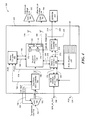
- a magnetic field sensor 10 includes a Hall effect element 12 driven by a current source 14.
- the Hall effect element 12 is responsive to a magnetic field as may be generated, for example, by a current 16a passing through a current-carrying conductor 16 proximate to the hall effect element 12.
- the current-carrying conductor 16 can be a part of the magnetic field sensor 10, or it can be external to the magnetic field sensor 10.
- the magnetic field sensor 10 includes an analog signal path comprised of an amplifier 18, a filter 20, which can be a programmable filter, a summing circuit 22, and an amplifier 24.
- the Hall effect element 12 is configured to generate a magnetic field signal 12a responsive to the magnetic field.
- the amplifier 18 (a gain adjustable analog circuit) is coupled to receive the magnetic field signal 12a and to receive a gain control signal 26a and configured to generate a gain adjusted signal 18a.
- the filter 20 is coupled to receive the gain adjusted signal 18a and configured to generate a filtered signal 20a.
- the summing circuit 22 (an offset adjustable analog circuit) is coupled to receive the filtered signal 20a and to receive an offset control signal 28a and configured to generate an offset adjusted signal 22a.
- the amplifier 24a is coupled to receive the offset adjusted signal 22a and configured to generate an output signal 24a having gain and offset correction.
- the magnetic field sensor 10 also includes a temperature sensor 30, preferably disposed on the same substrate as other circuits of the magnetic field sensor 10.
- the temperature sensor 30 is configured to generate a temperature signal 30a representative of a temperature experienced by the temperature sensor 30.
- An analog-to-digital converter (ADC) 32 is coupled to receive the temperature signal 30a and configured to generate a digital temperature signal 32a representative of the temperature signal 30a.
- ADC analog-to-digital converter
- the magnetic field sensor 10 can include a segment processor 34 coupled to receive the digital temperature signal 32a. It will become apparent from discussion below that the segment processor 34 is configured to perform several functions.
- the segment processor 34 is configured to identify a temperature segment in which the digital temperature signal 32a, (i.e. the temperature signal 30a) falls.
- the segment processor 34 can also be coupled to receive a pair of gain correction coefficients 52a and/or a pair of offset correction coefficients 52b associated with the identified temperature segment.
- the pair of gain correction coefficients 52a and/or pair of offset correction coefficients 52b are associated with temperatures that bound the identified temperature segment.
- the pair of gain correction coefficients 52a and/or pair of offset correction coefficients 52b can be requested by the segment processor 34.
- the segment processor 34 can be configured to interpolate between the pair of gain correction coefficients 52a in accordance with the digital temperature signal 32a to generate a sensor gain correction value 40a.
- the gain control signal 26a is an analog signal related to and determined by the sensor gain correction value 40a.
- the segment processor 34 can also be configured to interpolate between the pair of offset correction coefficients 52b in accordance with the digital temperature signal 32a to generate a sensor offset correction value 42a.
- the offset control signal 46a is an analog signal related to and determined by the sensor offset correction value 42a.
- segment processor 34 is a digital circuit that process digital signals or values.
- the segment processor 34 controls gain and/or offset of the analog circuits described above.
- the magnetic field sensor 10 can include an EEPROM 52 configured to hold a plurality of gain correction coefficients and/or a plurality of offset correction coefficients, each associated with a respective one of a plurality of selected temperatures. In some embodiments, there are five selected temperatures, each associated with a respective gain correction coefficient (TDSense) and a respective offset correction coefficient (DQVO).
- TDSense gain correction coefficient
- DQVO offset correction coefficient
- the plurality of gain correction coefficients and the plurality of offset correction coefficients can be stored in the EEPROM 52 at the time of manufacture of the magnetic field sensor 10, or at any time thereafter, via a signal 48a upon a communication link 48, which can be a serial communication link.
- a method of establishing the plurality of gain correction coefficients and the plurality of offset correction coefficients is described below in conjunction with FIG. 5 .
- the magnetic field sensor 10 can also include a user gain correction EEPROM 54 coupled to provide a user gain correction value 54a to the segment processor 34.
- the magnetic field sensor 10 can also include a user offset EEPROM 56 coupled to provide a user offset correction value 56a to the segment processor 34.
- the user gain EEPROM 54 can receive the user gain correction value 54a via a signal 48c upon the communication link.
- the user offset EEPROM 56 can receive the user offset correction value 56a via a signal 48d upon the communication link.
- the magnetic field sensor 10 can also include a program control EEPROM 50 coupled to provide an interpolation control signal 50a to the segment processor 34. Interpolation control is described more fully below.
- the program control EEPROM 50 can receive the interpolation control signal 50a via a signal 48b upon the communication link.
- the segment processor 34 can include an interpolation processor 36 coupled to receive the digital temperature signal 32a and coupled to receive the pair of gain correction coefficients 52a and/or the pair of offset correction coefficients 52b.
- the interpolation processor 36 can also be coupled to receive the control signal 50a.
- the control signal 50a can determine a type of gain and/or offset interpolation to be performed by the interpolation processor 36. Types of interpolation are further described below.
- the interpolation processor 36 is configured to generate an interpolated gain correction value 36a and/or an interpolated offset correction value 36b. To this end, the interpolation processor 36 is coupled to receive the digital temperature signal 32a and configured to identify the above-described temperature segment in which the digital temperature signal 32a, (i.e. the temperature signal 30a) falls. The interpolation processor 36 is also coupled to receive the above-described pair of gain correction coefficients 52a and/or the above-described pair of offset correction coefficients 52b associated with two temperatures that bound the identified temperature segment.
- the interpolation processor 36 can use the digital temperature signal 32a to identify in which one of the plurality of temperature segments the measured temperature lies. Accordingly, the proper pair of gain correction coefficients 52a and/or the pair of offset correction coefficients 52b can be requested by the interpolation processor 36.
- the magnetic field sensor 10 can include a combining processor 38 coupled to receive the interpolated gain correction value 36a and/or the interpolated offset correction value 36b and coupled to receive the user gain correction value 54a and/or the user offset correction value 56a.
- the combining processor is configured to combine the interpolated gain correction value 36a with the user gain correction value 54a and/or to combined the interpolated offset correction value 36b with the user offset correction value 56a.
- the combining processor 38 is configured to generate a combined gain correction value 38a and/or a combined offset correction value 38b, which can be stored in a gain adjust register 40 and an offset adjust register 42, respectively.
- a digital-to-analog converter (DAC) 44 can be coupled to receive the stored gain correction value 40a and configured to generate a gain correction signal 44a received by a gain adjust circuit 26 configured to generate the gain control signal 26a accordingly.
- a DAC 46 can be coupled to receive the stored offset correction value 42a and configured to generate an offset correction signal 46a received by an offset adjust circuit 28 configured to generate the offset control signal 28a accordingly.
- the interpolation processor 36 holds a plurality of gain (sensitivity) processing options and the processing option (the interpolation type, i.e., the equation above) is selected in accordance with the control signal 50a.
- the combining processor 38 combines the interpolated gain correction value 36a with the user gain correction value 54a according to an equation below to, resulting in the combined gain correction value 38a:
- SNS OUT coeffB - CoeffA 32 * t emp 4 : 0 + CoeffA * SENS FINE + K DEV - K DEV
- the interpolation processor 36 holds a plurality of offset processing options and the processing option (the interpolation type, i.e., the equation above) is selected in accordance with the control signal 50a.
- the selection can select among the following linear interpolation types, each differing by a factor of two (a one bit shift).
- QVO OUT CoeffB - CoeFFA 32 * t emp 4 : 0 + CoeffA 2
- QVO OUT CoeffB - CoeFFA 32 * t emp 4 : 0 + CoeffA CoeffB - CoeffA 32 * t emp 4 : 0 + CoeffA * 2
- the combining processor 38 combines the interpolated offset correction value 36b with the user offset correction value 56a according to an equation below to, resulting in the combined offset correction value 38a:
- QVO OUT CoeffB - CoeFFA 32 * t emp 4 : 0 + CoeffA + Q V O where: QVO is the user offset correction value 56a.
- the magnetic field sensor 10 when the magnetic field sensor 10 is used as a magnetic switch responsive to a proximity of a ferromagnetic object, the magnetic field sensor 10 can include a comparator 58 coupled to receive the signal 24a, coupled to receive a threshold signal 60, and configured to generate a comparison signal 58a.
- the comparison signal 58a can be a two state signal that can indicate the proximity or lack of proximity to the ferromagnetic object.
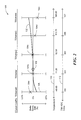
- a graph 100 has a vertical axis 108 with a scale in units of sensitivity change in percent.
- a first horizontal axis 110 has a scale in units of temperature in degrees Celsius experienced by a magnetic field sensor (i.e., by the temperature sensor 30 of FIG. 1 ) and a second horizontal axis 112 has a scale in units corresponding to a seven bit digital code representative of temperature, but in decimal units from zero to one hundred twenty seven.
- the axis 112 corresponds to the digital temperature signal 32a of FIG. 1 .
- a characteristic curve 102 is representative of a relative sensitivity (relative to sensitivity at room temperature 106) of a magnetic field sensor having no gain correction values applied. It can be seen that the relative sensitivity represented by the characteristic curve 102 tends to be lower at low and tends to be higher at high temperatures.
- a gain correction coefficient 104a (TDSense0) is opposite from the relative sensitivity drop of the characteristic curve 102. It will be understood that the gain correction coefficient 104a can be applied to the magnetic field sensor when the magnetic field sensor experiences the temperature of -40 degrees, resulting in essentially no sensitivity change from the sensitivity at room temperature 106. Similarly, other gain correction coefficients 104b, 104c, 104d, 104e (TDSense1, TDSense2, TDSense3, TDSense4, respectively) can be applied at other temperatures with which they are associated (11.25, 62.5, 113.75, 165.00 degrees Celsius, respectively) in order to provide no sensitivity change from the sensitivity at room temperature 106 at those particular temperatures.
- the interpolation processor 36 can interpolate between the gain correction coefficients (e.g., 104b, 104c) associated with boundaries of the identified temperature segment to establish an interpolated gain correction value (e.g., 36a, FIG. 1 ) to be used at the particular measured temperature.
- the interpolated gain correction value can be applied to the magnetic field sensor 10 to keep the sensitivity of the magnetic field sensor essentially unchanged from the sensitivity at room temperature 106.
- the sensitivity interpolation can be a linear interpolation.
- the gain interpolation can be of another form, for example, a quadratic interpolation.
- gain correction coefficients 104a-104e are shown and five associated temperature segments, in other embodiments, there can be more than five or fewer than five gain correction coefficients and associated temperature segments.
- the number of gain correction coefficients and associated temperature segments can be selected according to a desired accuracy and according to a desired largest physical size of the EEPROM 52 ( FIG. 1 ) that stores the gain correction coefficients. In general, the greater the number of gain correction coefficients that are stored in the EEPROM 52, the more accurate will be the interpolated gain correction coefficients and the more accurate will be the corrected relative sensitivity of the magnetic field sensor.
- temperature segments are shown to be equal in numbers of degrees, in other embodiments, the temperature segments can have an unequal number of degrees.
- temperature segments near to room temperature 106 can have a larger (or smaller) temperature span than temperature segments further from room temperature 106.
- Each individual magnetic field sensor of a particular type can have different gain correction coefficients 104a-104e generated by a process more fully described below in conjunction with FIG. 5 .
- each one of a particular type of magnetic field sensor can have the same gain correction coefficients 104a-104e.
- some of (or all of) the gain correction coefficients 104a-104e can be selected (i.e., measured) during production of the magnetic field sensor (or thereafter) by direct measurements of relative sensitivity at the plurality of temperatures of the specific one of the magnetic field sensors in which the specific gain correction coefficients 104a-104e are stored.
- fewer than all of the gain correction coefficients 104a-104e result from direct measurements and other ones of the gain correction coefficients 104a-104e are derived from the sensitivity characteristic curve 102.
- the gain correction coefficient 104a can be generated by a relative sensitivity measurement at - 40.00 degrees and at room temperature 106, and other ones of the gain correction coefficients 104b-104e can be deduced by knowledge of a shape of the sensitivity characteristic curve 102.
- the characteristic curve 102 as shown can be representative of an average sensitivity characteristic taken from a plurality of the same type of magnetic field sensor.
- Other types of magnetic field sensors can have characteristic curves with other shapes.
- the characteristic curve 102 can keep the same shape common to all of the same type of magnetic field sensors, but can be scaled up or down in magnitude for each individual magnetic field sensor of the same type. For example, if the relative sensitivity of an individual magnetic field sensor is measured at room temperature and also at -40 degrees, and if the relative sensitivity at -40 degrees is lower than that represented by the characteristic curve 102, it can be presumed that the characteristic curve of the magnetic field sensor being measured curves more downward at -40 degrees and more upward at 165 degrees, but otherwise maintains the same shape.
- the particular shape of the sensitivity characteristic curve 102 depends upon the particular type magnetic field sensor. Furthermore, the characteristic curve 102 can be slightly different (scaling) for different specific ones of the particular type of magnetic field sensor. Therefore, it may be advantageous to characterize a plurality of different specific ones of the particular type of magnetic field sensor, and take an average in order to identify the shape of the characteristic curve 102, which can thereafter be scaled up or down to suit each individual magnetic field sensor of the same type.
- a graph 100 has a vertical axis 128 with a scale in units of DC offset voltage change in linear units represented by a nine bit digital value.
- a first horizontal axis 130 has a scale in units of temperature in degrees Celsius experienced by a magnetic field sensor (i.e., by the temperature sensor 30 of FIG. 1 ) and a second horizontal axis 132 has a scale in units corresponding to a seven bit digital code representative of temperature, but in decimal units from zero to one hundred twenty seven.
- the axis 132 corresponds to the digital temperature signal 32a of FIG. 1 .
- a characteristic curve 122 is representative of a relative offset (relative to offset at room temperature 126) of a magnetic field sensor having no offset correction values applied. It can be seen that the offset represented by the characteristic curve 122 tends to be in one direction at low temperatures relative to the offset (nominally 2.5V) at room temperature and tends to be in the other direction at high temperatures relative to the offset at room temperature.
- an offset correction coefficient 124a (DQVO_0) is opposite from the relative offset drop of the characteristic curve 122. It will be understood that the offset correction coefficient 124a can be applied to the magnetic field sensor when the magnetic field sensor experiences the temperature of -40 degrees, resulting in essentially no offset change from the offset (2.5V) at room temperature 106. Similarly, other offset correction coefficients 124b, 124c, 124d, 124e (DQVO_1, DQVO_2, DQVO_3, DQVO_4, respectively) can be applied at other temperatures with which they are associated (11.25, 62.5, 113.75, 165.00 degrees Celsius, respectively) in order to provide no offset change from the offset at room temperature 106 at those particular temperatures.
- the interpolation processor 36 can interpolate between the offset correction coefficients (e.g., 124b, 124c) associated with boundaries of the temperature segment to establish an interpolated offset correction value (e.g., 36b, FIG. 1 ) to be used at the particular measured temperature.
- the interpolated offset correction value can be applied to the magnetic field sensor to keep the offset of the magnetic field sensor essentially unchanged from the offset at room temperature 106.
- the offset interpolation can be a linear interpolation.
- the offset interpolation can be of another form, for example, a quadratic interpolation.
- offset correction coefficients 124a-124e are shown and five associated temperature segments, in other embodiments, there can be more than five or fewer than five offset correction coefficients and associated temperature segments.
- the number of offset correction coefficients and associated temperature segments can be selected according to a desired offset accuracy and according to a desired largest physical size of the EEPROM 52 ( FIG. 1 ) that stores the offset correction coefficients. In general, the greater the number of offset correction coefficients that are stored in the EEPROM 52, the more accurate will be the interpolated offset correction coefficients and the more accurate will be the corrected relative offset of the magnetic field sensor.
- temperature segments are shown to be equal in numbers of degrees, in other embodiments, the temperature segments can have an unequal number of degrees.
- temperature segments near to room temperature 106 can have a larger (or smaller) temperature span than temperature segments further from room temperature 106.
- Each individual magnetic field sensor of a particular type can have different offset correction coefficients 124a-124e generated by a process more fully described below in conjunction with FIG. 5 .
- each one of a particular type of magnetic field sensor can have the same offset correction coefficients 124a-124e.
- some of (or all of) the offset correction coefficients 124a-124e can be selected (i.e., measured) during production of the magnetic field sensor (or thereafter) by direct measurements of relative offset at the plurality of temperatures of the specific one of the magnetic field sensors in which the specific offset correction coefficients 124a-124e are stored.
- fewer than all of the offset correction coefficients 124a-124e result from direct measurements and other ones of the offset correction coefficients 124a-124e are derived from the offset characteristic curve 122.
- the offset correction coefficient 124a can be generated by a relative offset measurement at -40.00 degrees and at room temperature 106, and other ones of the offset correction coefficients 124b-124e can be deduced by knowledge of a shape of the offset characteristic curve 122.
- the characteristic curve 122 as shown can be representative of an average offset characteristic taken from a plurality of the same type of magnetic field sensor.
- Other types of magnetic field sensors can have offset characteristic curves with other shapes.
- the offset characteristic curve 122 can keep the same shape common to all of the same type of magnetic field sensors, but can be scaled up or down in magnitude for each individual magnetic field sensor of the same type. For example, if the relative offset of an individual magnetic field sensor is measured at room temperature and also at -40 degrees, and if the relative offset at -40 degrees is lower than that represented by the characteristic curve 122, it can be presumed that the characteristic curve of the magnetic field sensor being measured curves more downward at -40 degrees and more upward at 165 degrees, but otherwise maintains the same shape.
- the particular shape of the offset characteristic curve 122 depends upon the particular type magnetic field sensor. Furthermore, the characteristic curve 122 can be slightly different (e.g., different scaling) for different specific ones of the particular type of magnetic field sensor. Therefore, it may be advantageous to characterize a plurality of different specific ones of the particular type of magnetic field sensor, and take an average in order to identify the shape of the offset characteristic curve 122, which can thereafter be scaled up or down to suit each individual magnetic field sensor of the same type.
- the EEPROM 52 of FIG. 1 is shown to store the exemplary five gain correction coefficients (TDSense0 to TDSense4) and the five exemplary offset correction coefficients (DQVO_0 to DQVO_4).
- a circuit 150 shows further details of the parts of magnetic field sensor 10 of FIG. 1 .
- An ADC 156 corresponds to the ADC 32 of FIG. 1 .
- the ADC 156 is coupled to receive an analog signal 154 that corresponds to the temperature signal 30a of FIG. 1 .
- the ADC 156 is configured to generate a signal 162 that corresponds to the digital temperature signal 32a of FIG. 1 .
- a segment processor 170 corresponds to the segment processor 34 of FIG. 1 .
- a multiplier and a summer 172, 174, respectively, within the segment processor 170, correspond to the combining processor 38 of FIG. 1 .
- a user gain correction value 54a, FIG. 1
- a user offset correction value 56a, FIG. 1
- a register 176 within the segment processor 170 corresponds to the gain adjust register 40 of FIG. 1 .
- a register 178 within the segment processor 170 corresponds to the offset adjust register 42 of FIG. 1 .
- DACS 188, 190 correspond to the DACS 44, 46, respectively, of FIG. 1 .
- the DAC 188 is coupled to receive a signal 184 from the segment processor 170, which signal corresponds to the signal 40a of FIG. 1 .
- the DAC 190 is coupled to receive a signal 186 from the segment processor 170, which signal corresponds to the signal 42a of FIG. 1 .
- An EEPROM 222 corresponds to the coefficient table EEPROM 52 of FIG. 1 .
- a bidirectional signal 220 from the EEPROM 222 corresponds to the selected pairs of gain correction values 52a and the selected pairs of offset correction values 52a, 52b, respectively, of FIG. 1 , and also to a selection signal to the EEPROM 222 not shown in FIG. 1 that selects the desired pair of gain correction values and the desired pairs of offset correction values in accordance with an identified temperature segment in which the digital temperature signal 162 lies.
- a signal 218 to the EEPROM 222 corresponds to a read/write control line to the EEPROM 222.
- Static registers 226 correspond to the user gain correction value EEPROM 54, the user offset correction value EEPROM 56 and the program control EEPROM 50 of FIG. 1 .
- a signal 228 from the static registers 226 correspond to the user gain correction value 54a and the user offset correction value 56a of FIG. 1 .
- a serial_in_out communication link 196 corresponds to the communication link 48 of FIG. 1 .
- a serial interface circuit 198 can be coupled to the serial communication link 196 and can understand one or more serial communication protocols in order to receive data from the serial communication link 196.
- the serial communication protocol is an automotive serial communication protocol, for example, a CAN communication protocol.
- the circuit 230 can include a memory controller 206 coupled to the serial interface circuit 198 with control and data signals 202, 204.
- the circuit 230 can also include an EEPROM controller 216 coupled to the memory controller 206 with data and control signal 212, 214.
- the EEPROM controller 216 can be coupled to the EEPROM 222 with the signals 218, 220 described above.
- the circuit 230 can also include a master controller 152, e.g., a programmable processor, coupled with data and control signals 180, 182 to the segment processor 170.
- a master controller 152 e.g., a programmable processor
- the circuit 230 can also include a dual slope ADC controller 166 coupled with control lines 158, 160 to the ADC 156.
- the dual slope ADC controller 166 can be configured to change a slope (i.e., a range) of the ADC 156 upon user control.
- a digital temperature signal 168 can have seven bits, the signal 184 can have nine bits, and the signal 186 can have nine bits.
- a power on reset signal (POR) 224 can distribute within the circuit 230 to reset function and various registers upon power up of the circuit 230.
- All of the circuit 150, and/or all of the magnetic field sensor 10 of FIG. 1 can be on a common integrated circuit substrate.
- FIG. 5 show a flowchart corresponding to the below contemplated technique that would be implemented in circuit 10 ( FIG. 1 ).
- Rectangular elements (typified by element 254 in FIG. 2 ), herein denoted “processing blocks,” represent computer software instructions or groups of instructions.
- Diamond shaped elements (none shown), herein denoted “decision blocks,” represent computer software instructions, or groups of instructions, which affect the execution of the computer software instructions represented by the processing blocks.
- the processing and decision blocks can represent steps performed by functionally equivalent circuits such as a digital signal processor circuit or an application specific integrated circuit (ASIC).
- ASIC application specific integrated circuit
- the flow diagrams do not depict the syntax of any particular programming language. Rather, the flow diagrams illustrate the functional information one of ordinary skill in the art requires to fabricate circuits or to generate computer software to perform the processing required of the particular apparatus. It should be noted that many routine program elements, such as initialization of loops and variables and the use of temporary variables are not shown. It will be appreciated by those of ordinary skill in the art that unless otherwise indicated herein, the particular sequence of blocks described is illustrative only and can be varied without departing from the spirit of the invention. Thus, unless otherwise stated the blocks described below are unordered meaning that, when possible, the steps can be performed in any convenient or desirable order.
- an exemplary method 250 begins at a set of blocks 252 that can be performed in a factory upon manufacture of the magnetic field sensor 10 of FIG. 1 .
- a set of calibration temperatures and associated temperature segments are selected.
- there can be five selected temperatures e.g., -40.00, 11.25, 62.5, 113.75, and 165.00 degrees Celsius and five associate temperature segments bounded by adjacent pairs of the selected temperatures.
- relative gains and relative offsets can be measured either at all of the selected temperatures, or at a subset of the selected temperatures, for example, only at -40.00 degrees Celsius.
- gain and offset correction coefficients are established for the temperature(s) at which measurements were taken.
- the gain and offset correction coefficients can be opposite from the measured relative sensitivity and relative offset deviations.
- other gain and offset correction coefficients can be established for the selected temperatures at which direct measurements of relative sensitivity and offset are not taken for the specific magnetic field sensor under consideration.
- the establishment of the other gain and offset correction coefficients can be made in accordance with generation of a sensitivity characteristic curve and/or an offset characteristic curve, using knowledge of the shape of the curves as derived from an average of measurements of a plurality of magnetic field sensors of the same type.
- the sensitivity (gain) characteristic curve and the offset characteristic curve can have the same shape as the average of the measurements, but can be scaled up or down in magnitude according to the sensitivity and offset measurement(s) made block 256.
- the gain and offset correction coefficients are stored within the magnetic field sensor, for example, within the EEPROM 52 of FIG. 1 via a serial communication link, for example, the communication link 48 of FIG. 1
- a gain interpolation equation and/or an offset interpolation type can be selected from among a plurality of interpolation types. See equations 1, 3, 4, and 5 above.
- the selection of the interpolation types can be saved as a value, for example, in the EEPROM 50 of FIG. 1 via the serial communication link, for example, the communication link 48 of FIG. 1 .
- the remaining blocks of the process 250 can be performed by the magnetic field sensor when in the field in normal operation, either continuously or from time to time.
- the magnetic field sensor measures its temperature, for example, via the temperature sensor 30 of FIG. 1 .
- the magnetic field sensor identifies in which one of the temperature segments selected at block 254 the measured temperature resides.
- the magnetic field sensor for example, the interpolation processor 272 of FIG. 1 , interpolates, in accordance with the measured temperature, between gain correction coefficients stored at block 262 that bound the identified temperature segment.
- An interpolated gain correction value (e.g., 36a of FIG. 1 ) is thus established.
- the interpolation can be in accordance with equation 1 above.
- the magnetic field sensor can receive a user gain correction value, for example the value 54a stored in the user gain correction value EEPROM 54 of FIG. 1 via the communication link 48 of FIG. 1 .
- the user gain correction value is used to merely adjust a sensitivity of the magnetic field sensor between factors of 0.75 and 1.25 according to user preference.
- the interpolated gain correction value is combined with the user gain correction value (e.g., by the combining processor 38 of FIG. 1 ) to establish a combined gain correction value (e.g., 38a of FIG. 1 ).
- the combined gain correction value is stored, for example, in the gain adjust register 40 of FIG. 1 .
- the saved gain correction value is applied to the magnetic field sensor to adjust its sensitivity (i.e., gain) via the DAC 44 and the gain adjust circuit 26 of FIG. 1 .
- the magnetic field sensor for example, the interpolation processor 272 of FIG. 1 , interpolates, in accordance with the measured temperature, between offset correction coefficients stored at block 262 that bound the identified temperature segment.
- An interpolated offset correction value (e.g., 36b of FIG. 1 ) is thus established.
- the interpolation can be in accordance with equation 3 above.
- the magnetic field sensor can receive a user offset correction value, for example the value 56a stored in the user offset correction value EEPROM 56 of FIG. 1 via the communication link 48 of FIG. 1 .
- the interpolated offset correction value is combined with the user offset correction value (e.g., by the combining processor 38 of FIG. 1 ) to establish a combined offset correction value (e.g., 38b of FIG. 1 ).
- the combined offset correction value is stored, for example, in the offset adjust register 42 of FIG. 1 .
- the saved offset correction value is applied to the magnetic field sensor to adjust its offset via the DAC 46 and the offset adjust circuit 28 of FIG. 1 .
- the magnetic field sensor can maintain a sensitivity and an offset that do not change or that change very little with respect to temperature of the magnetic field sensor compared to the sensitivity and offset of the magnetic field sensor at room temperature.
- a magnetic field sensor comprising:
- he magnetic field sensor of embodiment 4 further comprising a user offset correction value register coupled to receive a user offset correction value, wherein the combining processor is further coupled to receive the user offset correction value and coupled to receive the interpolated offset correction value and further configured to combine the user offset correction value with the interpolated offset correction value to generate a combined offset correction value, wherein the offset control signal is an analog signal related to the combined offset correction value.
- a method of adjusting a magnetic field sensor comprising:
- a magnetic field sensor comprising:
- the magnetic field sensor of embodiment 17, further comprising a user offset correction value register coupled to receive a user offset correction value
- the segment processor comprises a combining processor coupled to receive the user offset correction value and coupled to receive the interpolated offset correction value and further configured to combine the user offset correction value with the interpolated offset correction value to generate a combined offset correction value
- the offset control signal is an analog signal related to the combined offset correction value
- a method of adjusting a magnetic field sensor comprising:
Landscapes
- Physics & Mathematics (AREA)
- Condensed Matter Physics & Semiconductors (AREA)
- General Physics & Mathematics (AREA)
- Measuring Magnetic Variables (AREA)
- Indication And Recording Devices For Special Purposes And Tariff Metering Devices (AREA)
- Hall/Mr Elements (AREA)
Abstract
Description
- Not Applicable.
- Not Applicable.
- This invention relates generally to magnetic field sensors and, more particularly, to a magnetic field sensor that can adjust a gain and/or an offset in response to a sensed temperature.
- As is known, magnetic field sensors can be used in a variety of applications. In one application, a magnetic field sensor can be used to sense an electrical current. One type of current sensor uses a Hall effect magnetic field sensing element in proximity to a current-carrying conductor. The Hall effect magnetic field sensing element generates an output signal having a magnitude proportional to the magnetic field induced by the current through the conductor. Typical current sensors of this type include a gapped toroid magnetic flux concentrator, with the Hall effect device positioned in a toroid gap. The Hall effect device and toroid are assembled in a housing, which is mountable on a printed circuit board. In use, a separate current-carrying conductor, such as a wire, is passed through the center of the toroid and is soldered to the printed circuit board, such as by soldering exposed ends of the wire to plated through-holes.
- Other configurations of current sensors are known. Other configurations of current sensors are described in United States Patent No.
6,781,359, issued August 24, 2004 and United States Patent No.7,265, 531, issued September 4, 2007 , both of which are assigned to the assignee of the present invention and both of which are incorporated by reference herein in their entireties. - Various parameters characterize the performance of magnetic field sensors, e.g., current sensors. For example, a sensitivity of a magnetic field sensor is a change in the output signal of the magnetic field sensor in proportion to a magnetic field experienced by the magnetic field sensor. For another example, an offset voltage is an unwanted DC offset voltage of an output signal from the magnetic field sensor, normally biased at the power supply of the magnetic field sensor divided by two, for example, five volts divided by two or 2.5 Volts. For another example, a linearity is the degree to which the output signal of a magnetic field sensor varies in direct linear proportion to the magnetic field (e.g., current) experienced by the magnetic field sensor.
- It is known that some types of magnetic field sensors tend to have sensitivities and offsets that vary with temperature. Sensitivity variation tends to be related to a stress and/or strain imparted on a magnetic field sensing element used in the magnetic field sensor, for example, upon a Hall effect element, as temperature changes, for example, due to expansion or contraction of packaging of the magnetic field sensor or of the substrate on which the magnetic field sensing element is disposed. Offset variation tends to be related to temperature variable characteristics of amplifiers used in the magnetic field sensor.
- Magnetic field sensors sometimes employ analog compensation techniques that can adjust gain (i.e., sensitivity) and/or offset with respect to temperature, for example, using varistors or the like. Such techniques can result in sensitivities and offsets that are fairly invariant with respect to temperature, but often at the expense of room temperature accuracy of sensitivity or offset. Furthermore, analog compensation techniques are fixed and not suited for production or field changes to the compensation.
- Magnetic field sensors with digital circuits tend to be slower than magnetic field sensors with analog circuits. In other words, magnetic field sensors with digital circuits cannot respond well to rapidly changing magnetic fields (e.g., due to rapidly changing currents).
- It would be desirable to provide a magnetic field sensor with the speed advantages of analog circuits yet using a different technique for sensitivity and offset correction versus temperature.
- The present invention provides a magnetic field sensor with an analog signal path that is corrected for sensitivity and/or offset by digital circuits. This arrangement achieves the rapid response time of analog circuits, achieves sensitivity and/or offset accuracy, particularly at room temperature, and achieves production (or field) changeability without production perturbations.
- In accordance with one aspect of the present invention, a magnetic field sensor includes a magnetic field sensing element configured to generate a magnetic field signal. The magnetic field sensor also includes a gain adjustable analog circuit coupled to receive a signal representative of the magnetic field signal, coupled to receive a gain control signal, and configured to generate a gain adjusted signal having a gain responsive to the gain control signal. The magnetic field sensor also includes a coefficient table memory configured to receive and store a plurality of gain correction coefficients. Pairs of the plurality of gain correction coefficients are associated with boundaries of respective temperature segments, each temperature segment bounded by a pair of temperatures. The magnetic field sensor also includes a temperature sensor configured to generate a temperature signal representative of a temperature. The magnetic field sensor also includes a segment processor coupled to receive a signal representative of the temperature signal, configured to identify a temperature segment in which the temperature signal falls, coupled to receive a pair of gain correction coefficients associated with the identified temperature segment, and configured to interpolate between the pair of gain correction coefficients in accordance with the temperature signal to generate an interpolated gain correction value, wherein the gain control signal is an analog signal related to the interpolated gain correction value.
- In some embodiments, the magnetic field sensor also includes a user gain correction value register coupled to receive a user gain correction value, wherein the segment processor comprises a combining processor coupled to receive the user gain correction value, coupled to receive the interpolated gain correction value, and configured to combine the user gain correction value with the interpolated gain correction value to generate a combined gain correction value, wherein the gain control signal is an analog signal related to the combined gain correction value.
- In some embodiments, the magnetic field sensor also includes an offset adjustable analog circuit coupled to receive a signal representative of the magnetic field signal, coupled to receive an offset control signal, and configured to generate an offset adjusted signal having an offset responsive to the offset control signal, wherein the coefficient table memory is further configured to receive and store a plurality of offset correction coefficients, wherein pairs of the plurality of offset correction coefficients are associated with boundaries of respective temperature segments, wherein the segment processor is further coupled to receive a pair of offset correction coefficients associated with the identified temperature segment and configured to interpolate between the pair of offset correction coefficients in accordance with the temperature signal to generate an interpolated offset correction value, and wherein the offset control signal is an analog signal related to the interpolated offset correction value.
- In some embodiments, the magnetic field sensor also includes a user gain correction value register coupled to receive a user gain correction value, wherein the segment processor comprises a combining processor coupled to receive the user gain correction value and coupled to receive the interpolated gain correction value and configured to combine the user gain correction value with the interpolated gain correction value to generate a combined gain correction value, wherein the gain control signal is an analog signal related to the combined gain correction value.
- In some embodiments, the magnetic field sensor also includes a user offset correction value register coupled to receive a user offset correction value, wherein the combining processor is further coupled to receive the user offset correction value and coupled to receive the interpolated offset correction value and further configured to combine the user offset correction value with the interpolated offset correction value to generate a combined offset correction value, wherein the offset control signal is an analog signal related to the combined offset correction value.
- In some embodiments, the magnetic field sensor also includes a program control register coupled to receive a program control value, wherein the segment processor is coupled to receive a signal representative of the program control value, and, in response to the program control value, the segment processor is configured to select an interpolation type from among a plurality of predetermined interpolation types.
- In accordance with another aspect of the present invention, a method of adjusting a magnetic field sensor includes measuring a temperature with the magnetic field sensor during field operation. The method also includes identifying with the magnetic field sensor in which one of a predetermined plurality of temperature segments the field measured temperature lies. The method also includes identifying with the magnetic field sensor a pair of predetermined calibration temperatures associated with boundaries of the identified temperature segment. The method also includes identifying with the magnetic field sensor a pair of gain calibration coefficients associated with the boundaries of the identified temperature segment, the pair of gain calibration coefficients stored within the magnetic field sensor. The method also includes interpolating with the magnetic field sensor between the pair of gain calibration coefficients to establish an interpolated gain correction value. The method also includes applying an analog signal related to the interpolated gain correction value to a gain adjustment circuit within the magnetic field sensor.
- In some embodiments, the method also includes receiving a user gain correction value with the magnetic field sensor, combining with the magnetic field sensor the interpolated gain correction value and the user gain correction value to generate a combined gain correction value, and applying an analog signal related to the combined gain correction value to the gain adjustment circuit.
- In some embodiments, the method also includes identifying with the magnetic field sensor a pair of offset calibration coefficients associated with the boundaries of the identified temperature segment, the pair of offset calibration coefficients stored within the magnetic field sensor, interpolating with the magnetic field sensor between the pair of offset calibration coefficients to establish an interpolated offset correction value, and applying an analog signal related to the interpolated offset correction value to an offset adjustment circuit within the magnetic field sensor.
- In some embodiments, the method also includes receiving a user gain correction value with the magnetic field sensor, combining with the magnetic field sensor the interpolated gain correction value and the user gain correction value to generate a combined gain correction value, and applying an analog signal related to the combined gain correction value to the gain adjustment circuit.
- In some embodiments, the method also includes receiving a user offset correction value with the magnetic field sensor, combining with the magnetic field sensor the interpolated offset correction value and the user offset correction value to generate a combined offset correction value, and applying an analog signal related to the combined offset correction value to the offset adjustment circuit.
- In some embodiments, the method also includes receiving a program control value with the magnetic field sensor, and selecting with the magnetic field sensor an interpolation type from among a plurality of predetermined interpolation types in response to the program control value.
- In some embodiments, the method also includes measuring, during production of the magnetic field sensor, gains of the magnetic field sensor at a subset of the selected plurality of calibration temperatures, establishing gain correction coefficients at the subset of the plurality of calibration temperatures in accordance with the measurements, establishing additional gain correction coefficients at the other ones of the selected plurality of calibration temperatures, and storing the gain correction coefficients and the additional gain correction coefficients in the magnetic field sensor.
- In some embodiments of the method, the establishing the additional gain correction coefficients includes characterizing gain versus temperature of a plurality of magnetic field sensors.
- In some embodiments, the method also includes measuring, during production of the magnetic field sensor, offsets of the magnetic field sensor at the subset of the selected plurality of calibration temperatures, establishing offset correction coefficients at the subset of the plurality of calibration temperatures in accordance with the measurements, establishing additional offset correction coefficients at the other ones of the selected plurality of calibration temperatures, and storing the offset correction coefficients and the additional offset correction coefficients in the magnetic field sensor.
- In some embodiments of the method, the establishing the additional offset correction coefficients includes characterizing gain versus temperature of a plurality of magnetic field sensors, and characterizing offset versus temperature of the plurality of magnetic field sensors.
- In accordance with another aspect of the present invention, a magnetic field sensor includes a magnetic field sensing element configured to generate a magnetic field signal. The magnetic field sensor also includes an offset adjustable analog circuit coupled to receive a signal representative of the magnetic field signal, coupled to receive an offset control signal, and configured to generate an offset adjusted signal having an offset responsive to the offset control signal. The magnetic field sensor also includes a coefficient table memory configured to receive and store a plurality of offset correction coefficients. Pairs of the plurality of offset correction coefficients are associated with boundaries of respective temperature segments, each temperature segment bounded by a pair of temperatures. The magnetic field sensor also includes a temperature sensor configured to generate a temperature signal representative of a temperature. The magnetic field sensor also includes a segment processor coupled to receive a signal representative of the temperature signal, configured to identify a temperature segment in which the temperature signal falls, coupled to receive a pair of offset correction coefficients associated with the identified temperature segment, and configured to interpolate between the pair of offset correction coefficients in accordance with the temperature signal to generate an interpolated offset correction value. The offset control signal is an analog signal related to the interpolated offset correction value.
- In some embodiments, the magnetic field sensor also includes a user offset correction value register coupled to receive a user offset correction value, wherein the segment processor comprises a combining processor coupled to receive the user offset correction value and coupled to receive the interpolated offset correction value and further configured to combine the user offset correction value with the interpolated offset correction value to generate a combined offset correction value, wherein the offset control signal is an analog signal related to the combined offset correction value.
- In accordance with another aspect of the present invention, a method of adjusting a magnetic field sensor includes measuring a temperature with the magnetic field sensor during field operation. The method also includes identifying with the magnetic field sensor in which one of a predetermined plurality of temperature segments the field measured temperature lies. The method also includes identifying with the magnetic field sensor a pair of predetermined calibration temperatures associated with boundaries of the identified temperature segment. The method also includes identifying with the magnetic field sensor a pair of offset calibration coefficients associated with the boundaries of the identified temperature segment, the pair of offset calibration coefficients stored within the magnetic field sensor. The method also includes interpolating with the magnetic field sensor between the pair of offset calibration coefficients to establish an interpolated offset correction value. The method also includes applying an analog signal related to the interpolated offset correction value to an offset adjustment circuit within the magnetic field sensor.
- In some embodiments, the method also includes receiving a user offset correction value with the magnetic field sensor, combining with the magnetic field sensor the interpolated offset correction value and the user offset correction value to generate a combined offset correction value, and applying an analog signal related to the combined offset correction value to the offset adjustment circuit.
- The foregoing features of the invention, as well as the invention itself may be more fully understood from the following detailed description of the drawings, in which:
-
FIG. 1 is a block diagram showing a magnetic field sensor used to sense a current and having a digital segment processor to correct analog gain and/or offset variations versus temperature; -
FIG. 2 is a graph showing an exemplary characteristic curve of sensitivity versus temperature of a magnetic field sensor and showing gain correction coefficients; -
FIG. 3 is a graph showing an exemplary characteristic curve of offset versus temperature of a magnetic field sensor and showing offset correction coefficients; -
FIG. 4 is a block diagram showing details of the segment processor of the magnetic field sensor ofFIG. 1 ; -
FIG. 5 is a flow chart showing a process to correct gain and/or offset versus temperature of the magnetic field sensor ofFIG. 1 . - Before describing the present invention, some introductory concepts and terminology are explained. As used herein, the term "magnetic field sensing element" is used to describe a variety of electronic elements that can sense a magnetic field. The magnetic field sensing elements can be, but are not limited to, Hall effect elements, magnetoresistance elements, or magnetotransistors. As is known, there are different types of Hall effect elements, for example, a planar Hall element, a vertical Hall element, and a circular Hall element. As is also known, there are different types of magnetoresistance elements, for example, a giant magnetoresistance (GMR) element, an anisotropic magnetoresistance element (AMR), a tunneling magnetoresistance (TMR) element, an Indium antimonide (InSb) sensor, and a magnetic tunnel junction (MTJ).
- As is known, some of the above-described magnetic field sensing elements tend to have an axis of maximum sensitivity parallel to a substrate that supports the magnetic field sensing element, and others of the above-described magnetic field sensing elements tend to have an axis of maximum sensitivity perpendicular to a substrate that supports the magnetic field sensing element. In particular, most types of magnetoresistance elements tend to have axes of maximum sensitivity parallel to the substrate and most types of Hall elements tend to have axes of sensitivity perpendicular to a substrate.
- As used herein, the term "magnetic field sensor" is used to describe a circuit that includes a magnetic field sensing element. Magnetic field sensors are used in a variety of applications, including, but not limited to, a current sensor that senses a magnetic field generated by a current carried by a current-carrying conductor, a magnetic switch that senses the proximity of a ferromagnetic object, a rotation detector that senses passing ferromagnetic articles, for example, magnetic domains of a ring magnet, and a magnetic field sensor that senses a magnetic field density of a magnetic field.
- While magnetic field sensors having Hall effect elements are shown and described in examples below, the same techniques can be applied to a magnetic field sensor having any type of magnetic field sensing element. However, it is known that Hall effect elements tend to be particularly sensitive to stress and strains imparted upon the Hall effect element by temperature excursions, the stresses and strains tending to impart changes in sensitivity of the Hall effect elements.
- Current sensors are shown and described in examples, below. However, the same techniques can be applied to any magnetic field sensor, and, desirably, to any magnetic field sensor that experiences temperature excursions.
- Current sensors without flux concentrators are shown and described in examples below. It will be understood that the use of a flux concentrator tends to increase sensitivity of a magnetic field sensor. Circuits and techniques described below can also be used with magnetic field sensors having flux concentrators.
- Other configurations of current sensors to which this invention applies are described in United States Patent No.
6,781,359, issued August 24, 2004 and United States Patent No.7,265, 531, issued September 4, 2007 , both of which are assigned to the assignee of the present invention and both of which are incorporated by reference herein in their entireties. - Referring to
FIG. 1 , amagnetic field sensor 10 includes aHall effect element 12 driven by acurrent source 14. TheHall effect element 12 is responsive to a magnetic field as may be generated, for example, by a current 16a passing through a current-carryingconductor 16 proximate to thehall effect element 12. The current-carryingconductor 16 can be a part of themagnetic field sensor 10, or it can be external to themagnetic field sensor 10. - The
magnetic field sensor 10 includes an analog signal path comprised of anamplifier 18, afilter 20, which can be a programmable filter, a summingcircuit 22, and anamplifier 24. TheHall effect element 12 is configured to generate amagnetic field signal 12a responsive to the magnetic field. The amplifier 18 (a gain adjustable analog circuit) is coupled to receive themagnetic field signal 12a and to receive again control signal 26a and configured to generate a gain adjustedsignal 18a. Thefilter 20 is coupled to receive the gain adjustedsignal 18a and configured to generate afiltered signal 20a. The summing circuit 22 (an offset adjustable analog circuit) is coupled to receive the filteredsignal 20a and to receive an offsetcontrol signal 28a and configured to generate an offset adjustedsignal 22a. Theamplifier 24a is coupled to receive the offsetadjusted signal 22a and configured to generate anoutput signal 24a having gain and offset correction. - The
magnetic field sensor 10 also includes atemperature sensor 30, preferably disposed on the same substrate as other circuits of themagnetic field sensor 10. Thetemperature sensor 30 is configured to generate atemperature signal 30a representative of a temperature experienced by thetemperature sensor 30. An analog-to-digital converter (ADC) 32 is coupled to receive thetemperature signal 30a and configured to generate adigital temperature signal 32a representative of thetemperature signal 30a. - The
magnetic field sensor 10 can include asegment processor 34 coupled to receive thedigital temperature signal 32a. It will become apparent from discussion below that thesegment processor 34 is configured to perform several functions. Thesegment processor 34 is configured to identify a temperature segment in which thedigital temperature signal 32a, (i.e. thetemperature signal 30a) falls. Thesegment processor 34 can also be coupled to receive a pair ofgain correction coefficients 52a and/or a pair of offsetcorrection coefficients 52b associated with the identified temperature segment. The pair ofgain correction coefficients 52a and/or pair of offsetcorrection coefficients 52b are associated with temperatures that bound the identified temperature segment. The pair ofgain correction coefficients 52a and/or pair of offsetcorrection coefficients 52b can be requested by thesegment processor 34. - The
segment processor 34 can be configured to interpolate between the pair ofgain correction coefficients 52a in accordance with thedigital temperature signal 32a to generate a sensorgain correction value 40a. Thegain control signal 26a is an analog signal related to and determined by the sensorgain correction value 40a. - The
segment processor 34 can also be configured to interpolate between the pair of offsetcorrection coefficients 52b in accordance with thedigital temperature signal 32a to generate a sensor offsetcorrection value 42a. The offsetcontrol signal 46a is an analog signal related to and determined by the sensor offsetcorrection value 42a. - It will be understood that the
segment processor 34 is a digital circuit that process digital signals or values. Thesegment processor 34 controls gain and/or offset of the analog circuits described above. - The
magnetic field sensor 10 can include anEEPROM 52 configured to hold a plurality of gain correction coefficients and/or a plurality of offset correction coefficients, each associated with a respective one of a plurality of selected temperatures. In some embodiments, there are five selected temperatures, each associated with a respective gain correction coefficient (TDSense) and a respective offset correction coefficient (DQVO). - The plurality of gain correction coefficients and the plurality of offset correction coefficients can be stored in the
EEPROM 52 at the time of manufacture of themagnetic field sensor 10, or at any time thereafter, via asignal 48a upon acommunication link 48, which can be a serial communication link. A method of establishing the plurality of gain correction coefficients and the plurality of offset correction coefficients is described below in conjunction withFIG. 5 . - The
magnetic field sensor 10 can also include a usergain correction EEPROM 54 coupled to provide a usergain correction value 54a to thesegment processor 34. Themagnetic field sensor 10 can also include a user offset EEPROM 56 coupled to provide a user offsetcorrection value 56a to thesegment processor 34. Theuser gain EEPROM 54 can receive the usergain correction value 54a via asignal 48c upon the communication link. The user offset EEPROM 56 can receive the user offsetcorrection value 56a via asignal 48d upon the communication link. - The
magnetic field sensor 10 can also include aprogram control EEPROM 50 coupled to provide aninterpolation control signal 50a to thesegment processor 34. Interpolation control is described more fully below. Theprogram control EEPROM 50 can receive theinterpolation control signal 50a via asignal 48b upon the communication link. - The
segment processor 34 can include aninterpolation processor 36 coupled to receive thedigital temperature signal 32a and coupled to receive the pair ofgain correction coefficients 52a and/or the pair of offsetcorrection coefficients 52b. In some embodiments, theinterpolation processor 36 can also be coupled to receive thecontrol signal 50a. Thecontrol signal 50a can determine a type of gain and/or offset interpolation to be performed by theinterpolation processor 36. Types of interpolation are further described below. - The
interpolation processor 36 is configured to generate an interpolatedgain correction value 36a and/or an interpolated offsetcorrection value 36b. To this end, theinterpolation processor 36 is coupled to receive thedigital temperature signal 32a and configured to identify the above-described temperature segment in which thedigital temperature signal 32a, (i.e. thetemperature signal 30a) falls. Theinterpolation processor 36 is also coupled to receive the above-described pair ofgain correction coefficients 52a and/or the above-described pair of offsetcorrection coefficients 52b associated with two temperatures that bound the identified temperature segment. - The
interpolation processor 36 can use thedigital temperature signal 32a to identify in which one of the plurality of temperature segments the measured temperature lies. Accordingly, the proper pair ofgain correction coefficients 52a and/or the pair of offsetcorrection coefficients 52b can be requested by theinterpolation processor 36. - The
magnetic field sensor 10 can include a combiningprocessor 38 coupled to receive the interpolatedgain correction value 36a and/or the interpolated offsetcorrection value 36b and coupled to receive the usergain correction value 54a and/or the user offsetcorrection value 56a. The combining processor is configured to combine the interpolatedgain correction value 36a with the usergain correction value 54a and/or to combined the interpolated offsetcorrection value 36b with the user offsetcorrection value 56a. Accordingly, the combiningprocessor 38 is configured to generate a combinedgain correction value 38a and/or a combined offsetcorrection value 38b, which can be stored in a gain adjustregister 40 and an offset adjustregister 42, respectively. - A digital-to-analog converter (DAC) 44 can be coupled to receive the stored
gain correction value 40a and configured to generate again correction signal 44a received by a gain adjustcircuit 26 configured to generate thegain control signal 26a accordingly. ADAC 46 can be coupled to receive the stored offsetcorrection value 42a and configured to generate an offsetcorrection signal 46a received by an offset adjust circuit 28 configured to generate the offsetcontrol signal 28a accordingly. - In one particular embodiment, the gain interpolation performed by the
interpolation processor 36 to achieve the interpolatedgain correction value 36a is a linear interpolation of the form:
- where: CoeffA and CoeffB are the pair of
gain correction coefficients 52a bounding the identified temperature segment; and - temp[4:0] represents the five least significant bits of the
digital temperature signal 32a, which can be a seven bit value. - In some embodiments, the
interpolation processor 36 holds a plurality of gain (sensitivity) processing options and the processing option (the interpolation type, i.e., the equation above) is selected in accordance with thecontrol signal 50a. - In some embodiments, the combining
processor 38 combines the interpolatedgain correction value 36a with the usergain correction value 54a according to an equation below to, resulting in the combinedgain correction value 38a:
- where: SENSFINE is the user
gain correction value 54a; and - KDEV is a device specific constant representative of a sensitivity of the particular type of magnetic field sensor (e.g., decimal 74 or decimal 206)
- In one particular embodiment, the offset interpolation performed by the
interpolation processor 36 to achieve the interpolated offsetcorrection value 36b is a linear interpolation of the form:
- where: CoeffA and CoeffB are the pair of offset
correction coefficients 52b bounding the identified temperature segment; and - temp[4:0] represents the five least significant bits of the
digital temperature signal 32a, which can be a seven bit value. - In some embodiments, the
interpolation processor 36 holds a plurality of offset processing options and the processing option (the interpolation type, i.e., the equation above) is selected in accordance with thecontrol signal 50a. In some embodiments the selection can select among the following linear interpolation types, each differing by a factor of two (a one bit shift).


- In some embodiments, the combining
processor 38 combines the interpolated offsetcorrection value 36b with the user offsetcorrection value 56a according to an equation below to, resulting in the combined offsetcorrection value 38a:
where: QVO is the user offsetcorrection value 56a. - It should be apparent from the above gain and offset equations that the user
gain correction value 54a is applied in a product and the user offsetcorrection value 56a is applied in a sum, as would be expected. - In some alternate embodiments, for example, when the
magnetic field sensor 10 is used as a magnetic switch responsive to a proximity of a ferromagnetic object, themagnetic field sensor 10 can include acomparator 58 coupled to receive thesignal 24a, coupled to receive athreshold signal 60, and configured to generate acomparison signal 58a. Thecomparison signal 58a can be a two state signal that can indicate the proximity or lack of proximity to the ferromagnetic object. - Referring now to
FIG. 2 , agraph 100 has avertical axis 108 with a scale in units of sensitivity change in percent. A firsthorizontal axis 110 has a scale in units of temperature in degrees Celsius experienced by a magnetic field sensor (i.e., by thetemperature sensor 30 ofFIG. 1 ) and a secondhorizontal axis 112 has a scale in units corresponding to a seven bit digital code representative of temperature, but in decimal units from zero to one hundred twenty seven. Theaxis 112 corresponds to thedigital temperature signal 32a ofFIG. 1 . - A
characteristic curve 102 is representative of a relative sensitivity (relative to sensitivity at room temperature 106) of a magnetic field sensor having no gain correction values applied. It can be seen that the relative sensitivity represented by thecharacteristic curve 102 tends to be lower at low and tends to be higher at high temperatures. - At a first temperature, -40 degrees Celsius, a
gain correction coefficient 104a (TDSense0) is opposite from the relative sensitivity drop of thecharacteristic curve 102. It will be understood that thegain correction coefficient 104a can be applied to the magnetic field sensor when the magnetic field sensor experiences the temperature of -40 degrees, resulting in essentially no sensitivity change from the sensitivity atroom temperature 106. Similarly, othergain correction coefficients room temperature 106 at those particular temperatures. - Five temperature segments are shown, namely -40.00 to 11.25, 11.25 to 62.5, 62,5 to 113.75, and 113.75 to 165.00 degrees Celsius.
- Within any temperature segment, e.g., the temperature segment 11.25 to 62.5, identified in accordance with an actual measured temperature experienced by the magnetic field sensor as represented by the
digital temperature signal 32a ofFIG. 1 , the interpolation processor 36 (FIG. 1 ) can interpolate between the gain correction coefficients (e.g., 104b, 104c) associated with boundaries of the identified temperature segment to establish an interpolated gain correction value (e.g., 36a,FIG. 1 ) to be used at the particular measured temperature. The interpolated gain correction value can be applied to themagnetic field sensor 10 to keep the sensitivity of the magnetic field sensor essentially unchanged from the sensitivity atroom temperature 106. - As shown and described above, the sensitivity interpolation can be a linear interpolation. However in other embodiments, the gain interpolation can be of another form, for example, a quadratic interpolation.
- While five
gain correction coefficients 104a-104e are shown and five associated temperature segments, in other embodiments, there can be more than five or fewer than five gain correction coefficients and associated temperature segments. The number of gain correction coefficients and associated temperature segments can be selected according to a desired accuracy and according to a desired largest physical size of the EEPROM 52 (FIG. 1 ) that stores the gain correction coefficients. In general, the greater the number of gain correction coefficients that are stored in theEEPROM 52, the more accurate will be the interpolated gain correction coefficients and the more accurate will be the corrected relative sensitivity of the magnetic field sensor. - While the temperature segments are shown to be equal in numbers of degrees, in other embodiments, the temperature segments can have an unequal number of degrees. For example, in some embodiments, temperature segments near to
room temperature 106 can have a larger (or smaller) temperature span than temperature segments further fromroom temperature 106. - Each individual magnetic field sensor of a particular type can have different
gain correction coefficients 104a-104e generated by a process more fully described below in conjunction withFIG. 5 . However, in some embodiments, each one of a particular type of magnetic field sensor can have the samegain correction coefficients 104a-104e. - As further described below in conjunction with
FIG. 5 , some of (or all of) thegain correction coefficients 104a-104e can be selected (i.e., measured) during production of the magnetic field sensor (or thereafter) by direct measurements of relative sensitivity at the plurality of temperatures of the specific one of the magnetic field sensors in which the specificgain correction coefficients 104a-104e are stored. However in some embodiments, fewer than all of thegain correction coefficients 104a-104e result from direct measurements and other ones of thegain correction coefficients 104a-104e are derived from the sensitivitycharacteristic curve 102. In other words, for example, thegain correction coefficient 104a can be generated by a relative sensitivity measurement at - 40.00 degrees and atroom temperature 106, and other ones of thegain correction coefficients 104b-104e can be deduced by knowledge of a shape of the sensitivitycharacteristic curve 102. - The
characteristic curve 102 as shown can be representative of an average sensitivity characteristic taken from a plurality of the same type of magnetic field sensor. Other types of magnetic field sensors can have characteristic curves with other shapes. - In using the
characteristic curve 102 to derive some (or all) of thegain correction coefficients 104a-104e for a particular magnetic field sensor, it should be understood that thecharacteristic curve 102 can keep the same shape common to all of the same type of magnetic field sensors, but can be scaled up or down in magnitude for each individual magnetic field sensor of the same type. For example, if the relative sensitivity of an individual magnetic field sensor is measured at room temperature and also at -40 degrees, and if the relative sensitivity at -40 degrees is lower than that represented by thecharacteristic curve 102, it can be presumed that the characteristic curve of the magnetic field sensor being measured curves more downward at -40 degrees and more upward at 165 degrees, but otherwise maintains the same shape. Thus, by making only a room temperature sensitivity measurement and also a relative sensitivity measurement at any other temperature (relative to sensitivity at room temperature), a characteristic curve similar to (same shape as) the characteristic curve 102 (but with different scaling) can be derived and the other gain correction coefficients can be deduced. - It will be understood that the particular shape of the sensitivity
characteristic curve 102 depends upon the particular type magnetic field sensor. Furthermore, thecharacteristic curve 102 can be slightly different (scaling) for different specific ones of the particular type of magnetic field sensor. Therefore, it may be advantageous to characterize a plurality of different specific ones of the particular type of magnetic field sensor, and take an average in order to identify the shape of thecharacteristic curve 102, which can thereafter be scaled up or down to suit each individual magnetic field sensor of the same type. - Referring now to
FIG. 3 , agraph 100 has avertical axis 128 with a scale in units of DC offset voltage change in linear units represented by a nine bit digital value. A firsthorizontal axis 130 has a scale in units of temperature in degrees Celsius experienced by a magnetic field sensor (i.e., by thetemperature sensor 30 ofFIG. 1 ) and a secondhorizontal axis 132 has a scale in units corresponding to a seven bit digital code representative of temperature, but in decimal units from zero to one hundred twenty seven. Theaxis 132 corresponds to thedigital temperature signal 32a ofFIG. 1 . - A
characteristic curve 122 is representative of a relative offset (relative to offset at room temperature 126) of a magnetic field sensor having no offset correction values applied. It can be seen that the offset represented by thecharacteristic curve 122 tends to be in one direction at low temperatures relative to the offset (nominally 2.5V) at room temperature and tends to be in the other direction at high temperatures relative to the offset at room temperature. - At a first temperature, -40 degrees Celsius, an offset
correction coefficient 124a (DQVO_0) is opposite from the relative offset drop of thecharacteristic curve 122. It will be understood that the offsetcorrection coefficient 124a can be applied to the magnetic field sensor when the magnetic field sensor experiences the temperature of -40 degrees, resulting in essentially no offset change from the offset (2.5V) atroom temperature 106. Similarly, other offsetcorrection coefficients room temperature 106 at those particular temperatures. - As in
FIG. 2 , five temperature segments are shown, namely -40.00 to 11.25, 11.25 to 62.5, 62.5 to 113.75, and 113.75 to 165.00 degrees Celsius. - Within any temperature segment, e.g., the temperature segment 11.25 to 62.5, identified in accordance with an actual measured temperature experienced by the magnetic field sensor as represented by the
digital temperature signal 32a ofFIG. 1 , the interpolation processor 36 (FIG. 1 ) can interpolate between the offset correction coefficients (e.g., 124b, 124c) associated with boundaries of the temperature segment to establish an interpolated offset correction value (e.g., 36b,FIG. 1 ) to be used at the particular measured temperature. The interpolated offset correction value can be applied to the magnetic field sensor to keep the offset of the magnetic field sensor essentially unchanged from the offset atroom temperature 106. - As shown and described above, the offset interpolation can be a linear interpolation. However in other embodiments, the offset interpolation can be of another form, for example, a quadratic interpolation.
- While five offset
correction coefficients 124a-124e are shown and five associated temperature segments, in other embodiments, there can be more than five or fewer than five offset correction coefficients and associated temperature segments. The number of offset correction coefficients and associated temperature segments can be selected according to a desired offset accuracy and according to a desired largest physical size of the EEPROM 52 (FIG. 1 ) that stores the offset correction coefficients. In general, the greater the number of offset correction coefficients that are stored in theEEPROM 52, the more accurate will be the interpolated offset correction coefficients and the more accurate will be the corrected relative offset of the magnetic field sensor. - While the temperature segments are shown to be equal in numbers of degrees, in other embodiments, the temperature segments can have an unequal number of degrees. For example, in some embodiments, temperature segments near to
room temperature 106 can have a larger (or smaller) temperature span than temperature segments further fromroom temperature 106. - Each individual magnetic field sensor of a particular type can have different offset
correction coefficients 124a-124e generated by a process more fully described below in conjunction withFIG. 5 . However, in some embodiments, each one of a particular type of magnetic field sensor can have the same offsetcorrection coefficients 124a-124e. - As further described below in conjunction with
FIG. 5 , some of (or all of) the offsetcorrection coefficients 124a-124e can be selected (i.e., measured) during production of the magnetic field sensor (or thereafter) by direct measurements of relative offset at the plurality of temperatures of the specific one of the magnetic field sensors in which the specific offsetcorrection coefficients 124a-124e are stored. However in some embodiments, fewer than all of the offsetcorrection coefficients 124a-124e result from direct measurements and other ones of the offsetcorrection coefficients 124a-124e are derived from the offsetcharacteristic curve 122. In other words, for example, the offsetcorrection coefficient 124a can be generated by a relative offset measurement at -40.00 degrees and atroom temperature 106, and other ones of the offsetcorrection coefficients 124b-124e can be deduced by knowledge of a shape of the offsetcharacteristic curve 122. - The
characteristic curve 122 as shown can be representative of an average offset characteristic taken from a plurality of the same type of magnetic field sensor. Other types of magnetic field sensors can have offset characteristic curves with other shapes. - In using the offset
characteristic curve 122 to derive some (or all) of the offsetcorrection coefficients 124a-124e for a particular magnetic field sensor, it should be understood that the offsetcharacteristic curve 122 can keep the same shape common to all of the same type of magnetic field sensors, but can be scaled up or down in magnitude for each individual magnetic field sensor of the same type. For example, if the relative offset of an individual magnetic field sensor is measured at room temperature and also at -40 degrees, and if the relative offset at -40 degrees is lower than that represented by thecharacteristic curve 122, it can be presumed that the characteristic curve of the magnetic field sensor being measured curves more downward at -40 degrees and more upward at 165 degrees, but otherwise maintains the same shape. Thus, by making only a room temperature offset measurement and also a relative offset measurement at any other temperature (relative to offset at room temperature), a characteristic curve similar to (same shape as) the characteristic curve 122 (but with different scaling) can be derived and the other offset correction coefficients can be deduced. - It will be understood that the particular shape of the offset
characteristic curve 122 depends upon the particular type magnetic field sensor. Furthermore, thecharacteristic curve 122 can be slightly different (e.g., different scaling) for different specific ones of the particular type of magnetic field sensor. Therefore, it may be advantageous to characterize a plurality of different specific ones of the particular type of magnetic field sensor, and take an average in order to identify the shape of the offsetcharacteristic curve 122, which can thereafter be scaled up or down to suit each individual magnetic field sensor of the same type. - From the above examples of
FIGS. 2 and3 , it can be seen that in one embodiment, there are five gain correction coefficients associated with five temperatures and, five offset correction coefficients associated with the same five temperatures. However, the gain correction coefficients and the offset correction coefficients need not be associated with the same temperatures. TheEEPROM 52 ofFIG. 1 is shown to store the exemplary five gain correction coefficients (TDSense0 to TDSense4) and the five exemplary offset correction coefficients (DQVO_0 to DQVO_4). - Referring now to
FIG. 4 , acircuit 150 shows further details of the parts ofmagnetic field sensor 10 ofFIG. 1 . - An
ADC 156 corresponds to theADC 32 ofFIG. 1 . TheADC 156 is coupled to receive ananalog signal 154 that corresponds to thetemperature signal 30a ofFIG. 1 . TheADC 156 is configured to generate asignal 162 that corresponds to thedigital temperature signal 32a ofFIG. 1 . - A
segment processor 170 corresponds to thesegment processor 34 ofFIG. 1 . A multiplier and asummer segment processor 170, correspond to the combiningprocessor 38 ofFIG. 1 . As described above, it will be understood from equations above that a user gain correction value (54a,FIG. 1 ) is applied via a multiplication and a user offset correction value (56a,FIG. 1 ) is applied via a sum. Aregister 176 within thesegment processor 170 corresponds to the gain adjustregister 40 ofFIG. 1 . Aregister 178 within thesegment processor 170 corresponds to the offset adjustregister 42 ofFIG. 1 . -
DACS DACS FIG. 1 . TheDAC 188 is coupled to receive asignal 184 from thesegment processor 170, which signal corresponds to thesignal 40a ofFIG. 1 . TheDAC 190 is coupled to receive asignal 186 from thesegment processor 170, which signal corresponds to thesignal 42a ofFIG. 1 . - An
EEPROM 222 corresponds to thecoefficient table EEPROM 52 ofFIG. 1 . Abidirectional signal 220 from theEEPROM 222 corresponds to the selected pairs ofgain correction values 52a and the selected pairs of offsetcorrection values FIG. 1 , and also to a selection signal to theEEPROM 222 not shown inFIG. 1 that selects the desired pair of gain correction values and the desired pairs of offset correction values in accordance with an identified temperature segment in which thedigital temperature signal 162 lies. Asignal 218 to theEEPROM 222 corresponds to a read/write control line to theEEPROM 222. -
Static registers 226 correspond to the user gaincorrection value EEPROM 54, the user offset correction value EEPROM 56 and theprogram control EEPROM 50 ofFIG. 1 . Asignal 228 from thestatic registers 226 correspond to the usergain correction value 54a and the user offsetcorrection value 56a ofFIG. 1 . - A
serial_in_out communication link 196 corresponds to thecommunication link 48 ofFIG. 1 . - A
serial interface circuit 198 can be coupled to theserial communication link 196 and can understand one or more serial communication protocols in order to receive data from theserial communication link 196. In some embodiments, the serial communication protocol is an automotive serial communication protocol, for example, a CAN communication protocol. - The
circuit 230 can include amemory controller 206 coupled to theserial interface circuit 198 with control and data signals 202, 204. Thecircuit 230 can also include anEEPROM controller 216 coupled to thememory controller 206 with data andcontrol signal EEPROM controller 216 can be coupled to theEEPROM 222 with thesignals - The
circuit 230 can also include amaster controller 152, e.g., a programmable processor, coupled with data andcontrol signals segment processor 170. - In some embodiments, the
circuit 230 can also include a dualslope ADC controller 166 coupled withcontrol lines ADC 156. The dualslope ADC controller 166 can be configured to change a slope (i.e., a range) of theADC 156 upon user control. - As shown, in some embodiments, a
digital temperature signal 168 can have seven bits, thesignal 184 can have nine bits, and thesignal 186 can have nine bits. - A power on reset signal (POR) 224 can distribute within the
circuit 230 to reset function and various registers upon power up of thecircuit 230. - All of the
circuit 150, and/or all of themagnetic field sensor 10 ofFIG. 1 , can be on a common integrated circuit substrate. - It should be appreciated that
FIG. 5 show a flowchart corresponding to the below contemplated technique that would be implemented in circuit 10 (FIG. 1 ). Rectangular elements (typified byelement 254 inFIG. 2 ), herein denoted "processing blocks," represent computer software instructions or groups of instructions. Diamond shaped elements (none shown), herein denoted "decision blocks," represent computer software instructions, or groups of instructions, which affect the execution of the computer software instructions represented by the processing blocks. - The processing and decision blocks can represent steps performed by functionally equivalent circuits such as a digital signal processor circuit or an application specific integrated circuit (ASIC). The flow diagrams do not depict the syntax of any particular programming language. Rather, the flow diagrams illustrate the functional information one of ordinary skill in the art requires to fabricate circuits or to generate computer software to perform the processing required of the particular apparatus. It should be noted that many routine program elements, such as initialization of loops and variables and the use of temporary variables are not shown. It will be appreciated by those of ordinary skill in the art that unless otherwise indicated herein, the particular sequence of blocks described is illustrative only and can be varied without departing from the spirit of the invention. Thus, unless otherwise stated the blocks described below are unordered meaning that, when possible, the steps can be performed in any convenient or desirable order.
- Referring now to
FIG. 5 , anexemplary method 250 begins at a set ofblocks 252 that can be performed in a factory upon manufacture of themagnetic field sensor 10 ofFIG. 1 . Atblock 252, a set of calibration temperatures and associated temperature segments are selected. In the examples given above in conjunction withFIGS. 1-3 , there can be five selected temperatures, e.g., -40.00, 11.25, 62.5, 113.75, and 165.00 degrees Celsius and five associate temperature segments bounded by adjacent pairs of the selected temperatures. However, as described above there can be more than five or fewer than five selected temperatures and associated temperature segments, and the selected temperatures need not be evenly spaced. - At
block 256, relative gains and relative offsets (relative to gain and offset at room temperature) can be measured either at all of the selected temperatures, or at a subset of the selected temperatures, for example, only at -40.00 degrees Celsius. - At
block 258, based upon the relative sensitivity measurement(s), gain and offset correction coefficients are established for the temperature(s) at which measurements were taken. The gain and offset correction coefficients can be opposite from the measured relative sensitivity and relative offset deviations. - At
block 260, other gain and offset correction coefficients can be established for the selected temperatures at which direct measurements of relative sensitivity and offset are not taken for the specific magnetic field sensor under consideration. As described above, the establishment of the other gain and offset correction coefficients can be made in accordance with generation of a sensitivity characteristic curve and/or an offset characteristic curve, using knowledge of the shape of the curves as derived from an average of measurements of a plurality of magnetic field sensors of the same type. Using the same shape, the sensitivity (gain) characteristic curve and the offset characteristic curve can have the same shape as the average of the measurements, but can be scaled up or down in magnitude according to the sensitivity and offset measurement(s) madeblock 256. - At
block 262, the gain and offset correction coefficients (e.g., five gain correction coefficients and five offset correction coefficients) are stored within the magnetic field sensor, for example, within theEEPROM 52 ofFIG. 1 via a serial communication link, for example, thecommunication link 48 ofFIG. 1 - At
block 264, in some embodiments, a gain interpolation equation and/or an offset interpolation type (equation) can be selected from among a plurality of interpolation types. Seeequations - At
block 266, the selection of the interpolation types can be saved as a value, for example, in theEEPROM 50 ofFIG. 1 via the serial communication link, for example, thecommunication link 48 ofFIG. 1 . - The remaining blocks of the
process 250 can be performed by the magnetic field sensor when in the field in normal operation, either continuously or from time to time. - At
block 268, the magnetic field sensor measures its temperature, for example, via thetemperature sensor 30 ofFIG. 1 . - At
block 270, the magnetic field sensor identifies in which one of the temperature segments selected atblock 254 the measured temperature resides. - At
block 272, the magnetic field sensor, for example, theinterpolation processor 272 ofFIG. 1 , interpolates, in accordance with the measured temperature, between gain correction coefficients stored atblock 262 that bound the identified temperature segment. An interpolated gain correction value (e.g., 36a ofFIG. 1 ) is thus established. The interpolation can be in accordance withequation 1 above. - At
block 274 or earlier, the magnetic field sensor can receive a user gain correction value, for example thevalue 54a stored in the user gaincorrection value EEPROM 54 ofFIG. 1 via thecommunication link 48 ofFIG. 1 . In some embodiments, the user gain correction value is used to merely adjust a sensitivity of the magnetic field sensor between factors of 0.75 and 1.25 according to user preference. - At
block 276, the interpolated gain correction value is combined with the user gain correction value (e.g., by the combiningprocessor 38 ofFIG. 1 ) to establish a combined gain correction value (e.g., 38a ofFIG. 1 ). - At
block 278, the combined gain correction value is stored, for example, in the gain adjustregister 40 ofFIG. 1 . - At
block 280 the saved gain correction value is applied to the magnetic field sensor to adjust its sensitivity (i.e., gain) via theDAC 44 and the gain adjustcircuit 26 ofFIG. 1 . - At
block 282, the magnetic field sensor, for example, theinterpolation processor 272 ofFIG. 1 , interpolates, in accordance with the measured temperature, between offset correction coefficients stored atblock 262 that bound the identified temperature segment. An interpolated offset correction value (e.g., 36b ofFIG. 1 ) is thus established. The interpolation can be in accordance withequation 3 above. - At
block 284 or earlier, the magnetic field sensor can receive a user offset correction value, for example thevalue 56a stored in the user offset correction value EEPROM 56 ofFIG. 1 via thecommunication link 48 ofFIG. 1 . - At
block 286, the interpolated offset correction value is combined with the user offset correction value (e.g., by the combiningprocessor 38 ofFIG. 1 ) to establish a combined offset correction value (e.g., 38b ofFIG. 1 ). - At
block 288, the combined offset correction value is stored, for example, in the offset adjustregister 42 ofFIG. 1 . - At
block 290 the saved offset correction value is applied to the magnetic field sensor to adjust its offset via theDAC 46 and the offset adjust circuit 28 ofFIG. 1 . - With the above-described technique, the magnetic field sensor can maintain a sensitivity and an offset that do not change or that change very little with respect to temperature of the magnetic field sensor compared to the sensitivity and offset of the magnetic field sensor at room temperature.
- All references cited herein are hereby incorporated herein by reference in their entirety.
- Having described preferred embodiments, which serve to illustrate various concepts, structures and techniques, which are the subject of this patent, it will now become apparent to those of ordinary skill in the art that other embodiments incorporating these concepts, structures and techniques may be used. Accordingly, it is submitted that that scope of the patent should not be limited to the described embodiments but rather should be limited only by the spirit and scope of the following claims. In addition to the claimed embodiments in the appended claims, the following is a list of additional embodiments which may serve as the basis for additional claims in this application or subsequent divisional applications:
- A magnetic field sensor, comprising:
- a magnetic field sensing element configured to generate a magnetic field signal;
- a gain adjustable analog circuit coupled to receive a signal representative of the magnetic field signal, coupled to receive a gain control signal, and configured to generate a gain adjusted signal having a gain responsive to the gain control signal;
- a coefficient table memory configured to receive and store a plurality of gain correction coefficients, wherein pairs of the plurality of gain correction coefficients are associated with boundaries of respective temperature segments, each temperature segment bounded by a pair of temperatures;
- a temperature sensor configured to generate a temperature signal representative of a temperature; and
- a segment processor coupled to receive a signal representative of the temperature signal, configured to identify a temperature segment in which the temperature signal falls, coupled to receive a pair of gain correction coefficients associated with the identified temperature segment, and configured to interpolate between the pair of gain correction coefficients in accordance with the temperature signal to generate an interpolated gain correction value, wherein the gain control signal is an analog signal related to the interpolated gain correction value.
- The magnetic field sensor of
embodiment 1, further comprising a user gain correction value register coupled to receive a user gain correction value, wherein the segment processor comprises a combining processor coupled to receive the user gain correction value, coupled to receive the interpolated gain correction value, and configured to combine the user gain correction value with the interpolated gain correction value to generate a combined gain correction value, wherein the gain control signal is an analog signal related to the combined gain correction value. - The magnetic field sensor of
embodiment 1, further comprising: - an offset adjustable analog circuit coupled to receive a signal representative of the magnetic field signal, coupled to receive an offset control signal, and configured to generate an offset adjusted signal having an offset responsive to the offset control signal,
- wherein the coefficient table memory is further configured to receive and store a plurality of offset correction coefficients, wherein pairs of the plurality of offset correction coefficients are associated with boundaries of respective temperature segments,
- wherein the segment processor is further coupled to receive a pair of offset correction coefficients associated with the identified temperature segment and configured to interpolate between the pair of offset correction coefficients in accordance with the temperature signal to generate an interpolated offset correction value, and wherein the offset control signal is an analog signal related to the interpolated offset correction value.
- The magnetic field sensor of
embodiment 3, further comprising a user gain correction value register coupled to receive a user gain correction value, wherein the segment processor comprises a combining processor coupled to receive the user gain correction value and coupled to receive the interpolated gain correction value and configured to combine the user gain correction value with the interpolated gain correction value to generate a combined gain correction value, wherein the gain control signal is an analog signal related to the combined gain correction value. - he magnetic field sensor of
embodiment 4, further comprising a user offset correction value register coupled to receive a user offset correction value, wherein the combining processor is further coupled to receive the user offset correction value and coupled to receive the interpolated offset correction value and further configured to combine the user offset correction value with the interpolated offset correction value to generate a combined offset correction value, wherein the offset control signal is an analog signal related to the combined offset correction value. - The magnetic field sensor of
embodiment 1, further comprising a program control register coupled to receive a program control value, wherein the segment processor is coupled to receive a signal representative of the program control value, and, in response to the program control value, the segment processor is configured to select an interpolation type from among a plurality of predetermined interpolation types. - A method of adjusting a magnetic field sensor, comprising:
- measuring a temperature with the magnetic field sensor during field operation;
- identifying with the magnetic field sensor in which one of a predetermined plurality of temperature segments the field measured temperature lies;
- identifying with the magnetic field sensor a pair of predetermined calibration temperatures associated with boundaries of the identified temperature segment;
- identifying with the magnetic field sensor a pair of gain calibration coefficients associated with the boundaries of the identified temperature segment, the pair of gain calibration coefficients stored within the magnetic field sensor;
- interpolating with the magnetic field sensor between the pair of gain calibration coefficients to establish an interpolated gain correction value; and
- applying an analog signal related to the interpolated gain correction value to a gain adjustment circuit within the magnetic field sensor.
- The method of
embodiment 7, further comprising: - receiving a user gain correction value with the magnetic field sensor;
- combining with the magnetic field sensor the interpolated gain correction value and the user gain correction value to generate a combined gain correction value; and
- applying an analog signal related to the combined gain correction value to the gain adjustment circuit.
- The method of
embodiment 7, further comprising: - identifying with the magnetic field sensor a pair of offset calibration coefficients associated with the boundaries of the identified temperature segment, the pair of offset calibration coefficients stored within the magnetic field sensor;
- interpolating with the magnetic field sensor between the pair of offset calibration coefficients to establish an interpolated offset correction value; and
- applying an analog signal related to the interpolated offset correction value to an offset adjustment circuit within the magnetic field sensor.
- The method of embodiment 9, further comprising:
- receiving a user gain correction value with the magnetic field sensor;
- combining with the magnetic field sensor the interpolated gain correction value and the user gain correction value to generate a combined gain correction value; and
- applying an analog signal related to the combined gain correction value to the gain adjustment circuit.
- The method of
embodiment 10, further comprising: - receiving a user offset correction value with the magnetic field sensor;
- combining with the magnetic field sensor the interpolated offset correction value and the user offset correction value to generate a combined offset correction value; and
- applying an analog signal related to the combined offset correction value to the offset adjustment circuit.
- The method of
embodiment 7, further comprising: - receiving a program control value with the magnetic field sensor; and
- selecting with the magnetic field sensor an interpolation type from among a plurality of predetermined interpolation types in response to the program control value.
- The method of
embodiment 7, further comprising: - measuring, during production of the magnetic field sensor, gains of the magnetic field sensor at a subset of the selected plurality of calibration temperatures;
- establishing gain correction coefficients at the subset of the plurality of calibration temperatures in accordance with the measurements;
- establishing additional gain correction coefficients at the other ones of the selected plurality of calibration temperatures; and
- storing the gain correction coefficients and the additional gain correction coefficients in the magnetic field sensor.
- The method of embodiment 13, wherein the establishing the additional gain correction coefficients comprises:
- characterizing gain versus temperature of a plurality of magnetic field sensors.
- The method of embodiment 13, further comprising:
- measuring, during production of the magnetic field sensor, offsets of the magnetic field sensor at the subset of the selected plurality of calibration temperatures;
- establishing offset correction coefficients at the subset of the plurality of calibration temperatures in accordance with the measurements;
- establishing additional offset correction coefficients at the other ones of the selected plurality of calibration temperatures; and
- storing the offset correction coefficients and the additional offset correction coefficients in the magnetic field sensor.
- The method of embodiment 15, wherein the establishing the additional offset correction coefficients comprises:
- characterizing gain versus temperature of a plurality of magnetic field sensors; and
- characterizing offset versus temperature of the plurality of magnetic field sensors.
- A magnetic field sensor, comprising:
- a magnetic field sensing element configured to generate a magnetic field signal;
- an offset adjustable analog_circuit coupled to receive a signal representative of the magnetic field signal, coupled to receive an offset control signal, and configured to generate an offset adjusted signal having an offset responsive to the offset control signal;
- a coefficient table memory configured to receive and store a plurality of offset correction coefficients, wherein pairs of the plurality of offset correction coefficients are associated with boundaries of respective temperature segments, each temperature segment bounded by a pair of temperatures;
- a temperature sensor configured to generate a temperature signal representative of a temperature; and
- a segment processor coupled to receive a signal representative of the temperature signal, configured to identify a temperature segment in which the temperature signal falls, coupled to receive a pair of offset correction coefficients associated with the identified temperature segment, and configured to interpolate between the pair of offset correction coefficients in accordance with the temperature signal to generate an interpolated offset correction value, wherein the offset control signal is an analog signal related to the interpolated offset correction value.
- The magnetic field sensor of embodiment 17, further comprising a user offset correction value register coupled to receive a user offset correction value, wherein the segment processor comprises a combining processor coupled to receive the user offset correction value and coupled to receive the interpolated offset correction value and further configured to combine the user offset correction value with the interpolated offset correction value to generate a combined offset correction value, wherein the offset control signal is an analog signal related to the combined offset correction value.
- A method of adjusting a magnetic field sensor, comprising:
- measuring a temperature with the magnetic field sensor during field operation;
- identifying with the magnetic field sensor in which one of a predetermined plurality of temperature segments the field measured temperature lies;
- identifying with the magnetic field sensor a pair of predetermined calibration temperatures associated with boundaries of the identified temperature segment;
- identifying with the magnetic field sensor a pair of offset calibration coefficients associated with the boundaries of the identified temperature segment, the pair of offset calibration coefficients stored within the magnetic field sensor;
- interpolating with the magnetic field sensor between the pair of offset calibration coefficients to establish an interpolated offset correction value; and
- applying an analog signal related to the interpolated offset correction value to an offset adjustment circuit within the magnetic field sensor.
- The method of embodiment 19, further comprising:
- receiving a user offset correction value with the magnetic field sensor;
- combining with the magnetic field sensor the interpolated offset correction value and the user offset correction value to generate a combined offset correction value; and applying an analog signal related to the combined offset correction value to the offset adjustment circuit.
Claims (20)
- A magnetic field sensor, comprising:a magnetic field sensing element configured to generate a magnetic field signal;a gain adjustable analog circuit coupled to receive a signal representative of the magnetic field signal, coupled to receive a gain control signal, and configured to generate a gain adjusted signal having a gain responsive to the gain control signal;a coefficient table memory configured to receive and store a plurality of gain correction coefficients, wherein pairs of the plurality of gain correction coefficients are associated with boundaries of respective temperature segments, each temperature segment bounded by a pair of temperatures;a temperature sensor configured to generate a temperature signal representative of a temperature; anda segment processor coupled to receive a signal representative of the temperature signal, configured to identify a temperature segment in which the temperature signal falls, coupled to receive a pair of gain correction coefficients associated with the identified temperature segment, and configured to interpolate between the pair of gain correction coefficients in accordance with the temperature signal to generate an interpolated gain correction value, wherein the gain control signal is related to the interpolated gain correction value.
- The magnetic field sensor of Claim 1, further comprising a user gain correction value register coupled to receive a user gain correction value, wherein the segment processor comprises a combining processor coupled to receive the user gain correction value, coupled to receive the interpolated gain correction value, and configured to combine the user gain correction value with the interpolated gain correction value to generate a combined gain correction value, wherein the gain control signal is an analog signal related to the combined gain correction value.
- The magnetic field sensor of Claim 1 or 2, further comprising:an offset adjustable analog circuit coupled to receive a signal representative of the magnetic field signal, coupled to receive an offset control signal, and configured to generate an offset adjusted signal having an offset responsive to the offset control signal, wherein the coefficient table memory is further configured to receive and store a plurality of offset correction coefficients, wherein pairs of the plurality of offset correction coefficients are associated with boundaries of respective temperature segments,wherein the segment processor is further coupled to receive a pair of offset correction coefficients associated with the identified temperature segment and configured to interpolate between the pair of offset correction coefficients in accordance with the temperature signal to generate an interpolated offset correction value, and wherein the offset control signal is an analog signal related to the interpolated offset correction value.
- The magnetic field sensor of Claim 2 or 3, further comprising a user offset correction value register coupled to receive a user offset correction value, wherein the combining processor is further coupled to receive the user offset correction value and coupled to receive the interpolated offset correction value and further configured to combine the user offset correction value with the interpolated offset correction value to generate a combined offset correction value, wherein the offset control signal is an analog signal related to the combined offset correction value.
- The magnetic field sensor of Claim 1, further comprising a program control register coupled to receive a program control value, wherein the segment processor is coupled to receive a signal representative of the program control value, and, in response to the program control value, the segment processor is configured to select an interpolation type from among a plurality of predetermined interpolation types.
- A method of adjusting a magnetic field sensor, comprising:measuring a temperature with the magnetic field sensor during field operation;identifying with the magnetic field sensor in which one of a predetermined plurality of temperature segments the field measured temperature lies;identifying with the magnetic field sensor a pair of predetermined calibration temperatures associated with boundaries of the identified temperature segment;identifying with the magnetic field sensor a pair of gain calibration coefficients associated with the boundaries of the identified temperature segment, the pair of gain calibration coefficients stored within the magnetic field sensor;interpolating with the magnetic field sensor between the pair of gain calibration coefficients to establish an interpolated gain correction value; andapplying a signal related to the interpolated gain correction value to a gain adjustment circuit within the magnetic field sensor.
- The method of Claim 6, further comprising:receiving a user gain correction value with the magnetic field sensor;combining with the magnetic field sensor the interpolated gain correction value and the user gain correction value to generate a combined gain correction value; andapplying an analog signal related to the combined gain correction value to the gain adjustment circuit.
- The method of Claim 6 or 7, further comprising:identifying with the magnetic field sensor a pair of offset calibration coefficients associated with the boundaries of the identified temperature segment, the pair of offset calibration coefficients stored within the magnetic field sensor;interpolating with the magnetic field sensor between the pair of offset calibration coefficients to establish an interpolated offset correction value; andapplying an analog signal related to the interpolated offset correction value to an offset adjustment circuit within the magnetic field sensor.
- The method of Claim 6, further comprising:receiving a program control value with the magnetic field sensor; andselecting with the magnetic field sensor an interpolation type from among a plurality of predetermined interpolation types in response to the program control value.
- The method of Claim 6, further comprising:measuring, during production of the magnetic field sensor, gains of the magnetic field sensor at a subset of the selected plurality of calibration temperatures;establishing gain correction coefficients at the subset of the plurality of calibration temperatures in accordance with the measurements;establishing additional gain correction coefficients at the other ones of the selected plurality of calibration temperatures; andstoring the gain correction coefficients and the additional gain correction coefficients in the magnetic field sensor.
- The method of Claim 10, wherein the establishing the additional gain correction coefficients comprises:characterizing gain versus temperature of a plurality of magnetic field sensors.
- The method of Claim 10, further comprising:measuring, during production of the magnetic field sensor, offsets of the magnetic field sensor at the subset of the selected plurality of calibration temperatures;establishing offset correction coefficients at the subset of the plurality of calibration temperatures in accordance with the measurements;establishing additional offset correction coefficients at the other ones of the selected plurality of calibration temperatures; andstoring the offset correction coefficients and the additional offset correction coefficients in the magnetic field sensor.
- The method of Claim 12, wherein the establishing the additional offset correction coefficients comprises:characterizing gain versus temperature of a plurality of magnetic field sensors; andcharacterizing offset versus temperature of the plurality of magnetic field sensors.
- A magnetic field sensor, comprising:a magnetic field sensing element configured to generate a magnetic field signal;an offset adjustable analog circuit coupled to receive a signal representative of the magnetic field signal, coupled to receive an offset control signal, and configured to generate an offset adjusted signal having an offset responsive to the offset control signal;a coefficient table memory configured to receive and store a plurality of offset correction coefficients, wherein pairs of the plurality of offset correction coefficients are associated with boundaries of respective temperature segments, each temperature segment bounded by a pair of temperatures;a temperature sensor configured to generate a temperature signal representative of a temperature; anda segment processor coupled to receive a signal representative of the temperature signal, configured to identify a temperature segment in which the temperature signal falls, coupled to receive a pair of offset correction coefficients associated with the identified temperature segment, and configured to interpolate between the pair of offset correction coefficients in accordance with the temperature signal to generate an interpolated offset correction value, wherein the offset control signal is related to the interpolated offset correction value.
- The magnetic field sensor of Claim 14, further comprising a user offset correction value register coupled to receive a user offset correction value, wherein the segment processor comprises a combining processor coupled to receive the user offset correction value and coupled to receive the interpolated offset correction value and further configured to combine the user offset correction value with the interpolated offset correction value to generate a combined offset correction value, wherein the offset control signal is an analog signal related to the combined offset correction value.
- The magnetic field sensor of Claim 1 or 14, wherein temperature boundaries of the temperature segments are unequally spaced
- A method of adjusting a magnetic field sensor, comprising:measuring a temperature with the magnetic field sensor during field operation;identifying with the magnetic field sensor in which one of a predetermined plurality of temperature segments the field measured temperature lies;identifying with the magnetic field sensor a pair of predetermined calibration temperatures associated with boundaries of the identified temperature segment; identifying with the magnetic field sensor a pair of offset calibration coefficients associated with the boundaries of the identified temperature segment, the pair of offset calibration coefficients stored within the magnetic field sensor;interpolating with the magnetic field sensor between the pair of offset calibration coefficients to establish an interpolated offset correction value; andapplying a signal related to the interpolated offset correction value to an offset adjustment circuit within the magnetic field sensor.
- The method of Claim 8 or 17, further comprising:receiving a user offset correction value with the magnetic field sensor;combining with the magnetic field sensor the interpolated offset correction value and the user offset correction value to generate a combined offset correction value; andapplying an analog signal related to the combined offset correction value to the offset adjustment circuit.
- The method of Claim 6 or 17, wherein temperature boundaries of the plurality of temperature segments are unequally spaced.
- The magnetic field sensor of claim 1 or 14, wherein the segment processor is configured to carry out the interpolation as a nonlinear interpolation.
Applications Claiming Priority (2)
| Application Number | Priority Date | Filing Date | Title |
|---|---|---|---|
| US12/902,410 US8350563B2 (en) | 2010-10-12 | 2010-10-12 | Magnetic field sensor and method used in a magnetic field sensor that adjusts a sensitivity and/or an offset over temperature |
| EP11767332.7A EP2609441B1 (en) | 2010-10-12 | 2011-09-14 | Magnetic field sensor and method used in a magnetic field sensor that adjusts a sensitivity and/or an offset over temperature |
Related Parent Applications (1)
| Application Number | Title | Priority Date | Filing Date |
|---|---|---|---|
| EP11767332.7A Division EP2609441B1 (en) | 2010-10-12 | 2011-09-14 | Magnetic field sensor and method used in a magnetic field sensor that adjusts a sensitivity and/or an offset over temperature |
Publications (2)
| Publication Number | Publication Date |
|---|---|
| EP2899560A1 true EP2899560A1 (en) | 2015-07-29 |
| EP2899560B1 EP2899560B1 (en) | 2017-08-09 |
Family
ID=45924640
Family Applications (2)
| Application Number | Title | Priority Date | Filing Date |
|---|---|---|---|
| EP11767332.7A Active EP2609441B1 (en) | 2010-10-12 | 2011-09-14 | Magnetic field sensor and method used in a magnetic field sensor that adjusts a sensitivity and/or an offset over temperature |
| EP15156091.9A Active EP2899560B1 (en) | 2010-10-12 | 2011-09-14 | Magnetic field sensor and method used in a magnetic field sensor that adjusts a sensitivity and/or an offset over temperature |
Family Applications Before (1)
| Application Number | Title | Priority Date | Filing Date |
|---|---|---|---|
| EP11767332.7A Active EP2609441B1 (en) | 2010-10-12 | 2011-09-14 | Magnetic field sensor and method used in a magnetic field sensor that adjusts a sensitivity and/or an offset over temperature |
Country Status (5)
| Country | Link |
|---|---|
| US (2) | US8350563B2 (en) |
| EP (2) | EP2609441B1 (en) |
| JP (2) | JP2013545085A (en) |
| KR (2) | KR101943337B1 (en) |
| WO (1) | WO2012050711A1 (en) |
Cited By (1)
| Publication number | Priority date | Publication date | Assignee | Title |
|---|---|---|---|---|
| CN111596236A (en) * | 2020-06-11 | 2020-08-28 | 赛卓电子科技(上海)有限公司 | Magnetic field sensor with sensitivity correction and offset correction functions and implementation method |
Families Citing this family (71)
| Publication number | Priority date | Publication date | Assignee | Title |
|---|---|---|---|---|
| US8122159B2 (en) | 2009-01-16 | 2012-02-21 | Allegro Microsystems, Inc. | Determining addresses of electrical components arranged in a daisy chain |
| DE102010019484B9 (en) * | 2010-05-05 | 2012-12-06 | Austriamicrosystems Ag | Sensor arrangement and method for operating a sensor arrangement |
| DE102010019485B4 (en) * | 2010-05-05 | 2012-10-31 | Austriamicrosystems Ag | Sensor arrangement and method for operating a sensor arrangement |
| US8598867B2 (en) | 2010-06-04 | 2013-12-03 | Allegro Microsystems, Llc | Circuits and methods for generating a threshold signal used in a motion detector |
| US8350563B2 (en) | 2010-10-12 | 2013-01-08 | Allegro Microsystems, Inc. | Magnetic field sensor and method used in a magnetic field sensor that adjusts a sensitivity and/or an offset over temperature |
| US8515001B2 (en) * | 2010-12-24 | 2013-08-20 | Lg Display Co., Ltd. | Shift register |
| US8736260B2 (en) | 2012-01-06 | 2014-05-27 | Allegro Microsystems, Llc | Magnetic field sensor and associated method that can establish a measured threshold value and that can store the measured threshold value in a memory device |
| US9395391B2 (en) | 2013-03-15 | 2016-07-19 | Allegro Microsystems, Llc | Magnetic field sensor and associated method that can store a measured threshold value in a memory device during a time when the magnetic field sensor is powered off |
| US10845434B2 (en) | 2012-01-06 | 2020-11-24 | Allegro Microsystems, Llc | Magnetic field sensor having a temperature compensated threshold on power up |
| JPWO2014002387A1 (en) | 2012-06-29 | 2016-05-30 | 旭化成エレクトロニクス株式会社 | Hall electromotive force correction apparatus and hall electromotive force correction method |
| US9354123B2 (en) * | 2012-12-26 | 2016-05-31 | Allegro Microsystems, Llc | Systems and methods for processing temperature data or other signals |
| US9134383B2 (en) | 2012-12-28 | 2015-09-15 | Asahi Kasei Microdevices Corporation | Hall device, magnetic sensor having same, and signal correcting method thereof |
| US9389060B2 (en) | 2013-02-13 | 2016-07-12 | Allegro Microsystems, Llc | Magnetic field sensor and related techniques that provide an angle error correction module |
| US9829543B2 (en) | 2013-06-18 | 2017-11-28 | Infineon Technologies Ag | Sensor arrangement having thermo-EMF compensation |
| US9400164B2 (en) | 2013-07-22 | 2016-07-26 | Allegro Microsystems, Llc | Magnetic field sensor and related techniques that provide an angle correction module |
| EP3036547A2 (en) | 2013-08-30 | 2016-06-29 | Allegro Microsystems, LLC | Circuits and methods for generating a threshold signal used in a motion detector in accordance with a least common multiple of a set of possible quantities of features upon a target |
| US10120042B2 (en) | 2013-12-23 | 2018-11-06 | Allegro Microsystems, Llc | Magnetic field sensor and related techniques that inject a synthesized error correction signal into a signal channel to result in reduced error |
| US9574867B2 (en) * | 2013-12-23 | 2017-02-21 | Allegro Microsystems, Llc | Magnetic field sensor and related techniques that inject an error correction signal into a signal channel to result in reduced error |
| US9787495B2 (en) | 2014-02-18 | 2017-10-10 | Allegro Microsystems, Llc | Signaling between master and slave components using a shared communication node of the master component |
| US9634715B2 (en) | 2014-02-18 | 2017-04-25 | Allegro Microsystems, Llc | Signaling between master and slave components using a shared communication node of the master component |
| US9172565B2 (en) | 2014-02-18 | 2015-10-27 | Allegro Microsystems, Llc | Signaling between master and slave components using a shared communication node of the master component |
| US9041390B1 (en) * | 2014-09-03 | 2015-05-26 | Neilsen-Kuljian, Inc. | Digitally controlled high-current DC transducer |
| US9841485B2 (en) * | 2014-11-14 | 2017-12-12 | Allegro Microsystems, Llc | Magnetic field sensor having calibration circuitry and techniques |
| US9804222B2 (en) | 2014-11-14 | 2017-10-31 | Allegro Microsystems, Llc | Magnetic field sensor with shared path amplifier and analog-to-digital-converter |
| US10466298B2 (en) | 2014-11-14 | 2019-11-05 | Allegro Microsystems, Llc | Magnetic field sensor with shared path amplifier and analog-to-digital-converter |
| KR102254098B1 (en) | 2014-11-20 | 2021-05-20 | 삼성전자주식회사 | A semiconductor chip capable of sensing a temparature, and a semiconductor system including the semiconductor chip |
| TWI582447B (en) | 2014-12-11 | 2017-05-11 | 財團法人工業技術研究院 | Magnetic sensing apparatus and magnetic sensing method thereof |
| JP2016161276A (en) * | 2015-02-26 | 2016-09-05 | 日本セラミック株式会社 | Current sensor circuit |
| US9523742B2 (en) | 2015-04-27 | 2016-12-20 | Allegro Microsystems, Llc | Circuits and methods for modulating current in circuits comprising sensing elements |
| US11163022B2 (en) | 2015-06-12 | 2021-11-02 | Allegro Microsystems, Llc | Magnetic field sensor for angle detection with a phase-locked loop |
| US10209279B2 (en) | 2015-06-24 | 2019-02-19 | Allegro Microsystems, Llc | Methods and apparatus for monitoring a level of a regulated source |
| US11402440B2 (en) * | 2015-07-17 | 2022-08-02 | Allegro Microsystems, Llc | Methods and apparatus for trimming a magnetic field sensor |
| DE102015117109B4 (en) | 2015-10-07 | 2025-07-10 | Infineon Technologies Ag | Digitally controlled output amplitude of an analog sensor signal |
| US10261137B2 (en) * | 2015-11-09 | 2019-04-16 | Infineon Technologies Ag | Magnetic sensor |
| DE102016224958B4 (en) * | 2015-12-14 | 2021-06-24 | Infineon Technologies Ag | Sensor arrangement with thermal EMF compensation |
| US10132879B2 (en) * | 2016-05-23 | 2018-11-20 | Allegro Microsystems, Llc | Gain equalization for multiple axis magnetic field sensing |
| US10120017B2 (en) * | 2016-07-15 | 2018-11-06 | Allegro Microsystems, Llc | Enabling testing of an integrated circuit at a single temperature |
| DE102017215270A1 (en) * | 2016-09-29 | 2018-03-29 | Robert Bosch Gmbh | Sensor module, safety system |
| CN109791169A (en) * | 2016-11-17 | 2019-05-21 | 株式会社村田制作所 | Current sensor |
| GB2557272B (en) | 2016-12-02 | 2020-03-18 | Cmr Surgical Ltd | Sensing motor current |
| DE102016225305B4 (en) | 2016-12-16 | 2019-07-11 | Fraunhofer-Gesellschaft zur Förderung der angewandten Forschung e.V. | Method for offset compensation of a sensor signal of a Hall sensor and sensor arrangement |
| JP6897107B2 (en) * | 2017-01-17 | 2021-06-30 | 日立金属株式会社 | Signal correction method for current sensor and current sensor |
| EP3410075B1 (en) * | 2017-05-30 | 2020-10-07 | MEAS France | Temperature compensation for magnetic field sensing devices and a magnetic field sensing device using the same |
| JP6620796B2 (en) * | 2017-07-28 | 2019-12-18 | Tdk株式会社 | Offset estimation apparatus and method, magnetic sensor correction apparatus, and current sensor |
| EP3457154B1 (en) * | 2017-09-13 | 2020-04-08 | Melexis Technologies SA | Stray field rejection in magnetic sensors |
| US10839920B2 (en) | 2017-09-29 | 2020-11-17 | Allegro Microsystems, Llc | Circuit having a low power charge pump for storing information in non-volatile memory during a loss of power event |
| US10430296B2 (en) | 2017-09-29 | 2019-10-01 | Allegro Microsystems, Llc | Circuit and method for storing information in non-volatile memory during a loss of power event |
| JP2019074437A (en) * | 2017-10-17 | 2019-05-16 | 日本セラミック株式会社 | Current sensor circuit |
| US10747708B2 (en) | 2018-03-08 | 2020-08-18 | Allegro Microsystems, Llc | Communication system between electronic devices |
| JP7006633B2 (en) * | 2019-02-13 | 2022-01-24 | Tdk株式会社 | Magnetic sensor system |
| US12326485B2 (en) * | 2019-04-28 | 2025-06-10 | Harcosemco Llc | Temperature compensation method for hall effect proximity sensors |
| US10921341B2 (en) | 2019-05-09 | 2021-02-16 | Allegro Microsystems, Llc | Methods and apparatus for generating a uniform response in a magnetic field sensor |
| US11402280B2 (en) * | 2019-08-12 | 2022-08-02 | Allegro Microsystems, Llc | Magnetic sensor with improved stress compensation accounting for temperature |
| US11125837B2 (en) * | 2020-01-14 | 2021-09-21 | Allegro Microsystems, Llc | Magnetic field sensor offset and gain adjustment |
| US11169223B2 (en) | 2020-03-23 | 2021-11-09 | Allegro Microsystems, Llc | Hall element signal calibrating in angle sensor |
| US11029370B1 (en) | 2020-05-22 | 2021-06-08 | Allegro Microsystems, Llc | Sensor output control methods and apparatus |
| US12307351B2 (en) | 2020-09-09 | 2025-05-20 | Allegro Microsystems, Llc | Method and apparatus for trimming sensor output using a neural network engine |
| KR102597256B1 (en) | 2020-12-21 | 2023-11-03 | 재단법인대구경북과학기술원 | Magnetic sensor based on wheatstone bridge and manufacturing method thereof |
| US12174275B2 (en) | 2021-01-04 | 2024-12-24 | Allegro Microsystems, Llc | Magnetic field closed loop sensors with offset reduction |
| US11630130B2 (en) | 2021-03-31 | 2023-04-18 | Allegro Microsystems, Llc | Channel sensitivity matching |
| KR20220140980A (en) | 2021-04-12 | 2022-10-19 | 삼성전자주식회사 | An electronic device compensating for geomagnetic sensing data and method for controlling the same |
| US11473935B1 (en) | 2021-04-16 | 2022-10-18 | Allegro Microsystems, Llc | System and related techniques that provide an angle sensor for sensing an angle of rotation of a ferromagnetic screw |
| US11885645B2 (en) | 2021-06-17 | 2024-01-30 | Allegro Microsystems, Llc | Supply voltage configurable sensor |
| US11733025B2 (en) | 2021-10-14 | 2023-08-22 | Allegro Microsystems, Llc | Dynamic offset and amplitude tracker |
| US11650271B1 (en) | 2022-03-30 | 2023-05-16 | Ev Advanced Material Co., Ltd. | Magnetic sensor based on wheatstone bridge and manufacturing method thereof |
| US20240192575A1 (en) * | 2022-12-07 | 2024-06-13 | Lx Semicon Co., Ltd. | Analog front-end circuit and camera module control driver including the same |
| KR102788102B1 (en) * | 2023-04-20 | 2025-03-31 | 주식회사 해치텍 | A magnetic sensor |
| US12510611B2 (en) | 2023-11-07 | 2025-12-30 | Allegro Microsystems, Llc | TMR sensor having magnetic field generation for pillar stimulation |
| US12613293B2 (en) | 2023-12-04 | 2026-04-28 | Allegro Microsystems, Llc | Sensor with common mode rejection and offset correction |
| US12517195B2 (en) | 2023-12-04 | 2026-01-06 | Allegro Microsystems, Llc | Low residual offset sensor |
| US12455301B2 (en) | 2023-12-11 | 2025-10-28 | Allegro Microsystems, Llc | Hall plate current sensor having stress compensation |
Citations (3)
| Publication number | Priority date | Publication date | Assignee | Title |
|---|---|---|---|---|
| US6781359B2 (en) | 2002-09-20 | 2004-08-24 | Allegro Microsystems, Inc. | Integrated current sensor |
| US20060224350A1 (en) * | 2005-03-31 | 2006-10-05 | Denso Corporation | Physical quantity detecting method and sensor device |
| US20080074106A1 (en) * | 2006-06-02 | 2008-03-27 | Denso Corporation | Semiconductor device, magnetic sensor, and physical quantity sensor |
Family Cites Families (38)
| Publication number | Priority date | Publication date | Assignee | Title |
|---|---|---|---|---|
| US4293814A (en) | 1979-08-08 | 1981-10-06 | Ford Motor Company | Crankshaft position sensor circuitry for providing stable cyclical output signals without regard to peak to peak variations in sensor signals |
| JPS60119345A (en) | 1983-12-01 | 1985-06-26 | Nippon Soken Inc | Control method of internal-combustion engine |
| US5018116A (en) | 1990-05-04 | 1991-05-21 | Magnavox Government And Industrial Electronics Company | Inter-element mounting for stacked piezoelectric transducers |
| JP2749181B2 (en) | 1990-05-11 | 1998-05-13 | 株式会社日立製作所 | Internal combustion engine operation control method and electronic control device thereof |
| JPH0440007A (en) * | 1990-06-05 | 1992-02-10 | Matsushita Electric Ind Co Ltd | Temperature compensator and method of preparing temperature compensating data |
| US6242908B1 (en) | 1996-01-17 | 2001-06-05 | Allegro Microsystems, Inc. | Detection of passing magnetic articles while adapting the detection threshold |
| US6525531B2 (en) | 1996-01-17 | 2003-02-25 | Allegro, Microsystems, Inc. | Detection of passing magnetic articles while adapting the detection threshold |
| US5917320A (en) | 1996-01-17 | 1999-06-29 | Allegro Microsystems, Inc. | Detection of passing magnetic articles while periodically adapting detection threshold |
| US6297627B1 (en) | 1996-01-17 | 2001-10-02 | Allegro Microsystems, Inc. | Detection of passing magnetic articles with a peak-to-peak percentage threshold detector having a forcing circuit and automatic gain control |
| JPH11287668A (en) | 1998-02-04 | 1999-10-19 | Denso Corp | Amplifying circuit and position detecting device using the same |
| JPH11257993A (en) * | 1998-03-10 | 1999-09-24 | Toshiba Corp | Digital relay |
| JP2000258162A (en) * | 1999-03-04 | 2000-09-22 | Alps Electric Co Ltd | Temperature compensation device for piezoelectric vibrator |
| JP2001153745A (en) * | 1999-11-30 | 2001-06-08 | Hokuriku Electric Ind Co Ltd | Sensor temperature compensation method and device |
| DE10139149A1 (en) | 2001-08-09 | 2003-02-20 | Bosch Gmbh Robert | Toothed type rotational velocity sensor, especially for use in combustion engines, has means for checking if the assumed position of a toothed wheel relative to a sensor at engine start-up is correct or not |
| JP2003315770A (en) * | 2002-04-25 | 2003-11-06 | Hitachi Ltd | Terminal device |
| JP3966186B2 (en) * | 2003-02-17 | 2007-08-29 | 松下電工株式会社 | Electric quantity detection sensor |
| US20060197524A1 (en) | 2003-03-03 | 2006-09-07 | Beck Gabriele M | Magnetic resonance imaging method |
| JP3956877B2 (en) * | 2003-03-18 | 2007-08-08 | 株式会社デンソー | Sensor temperature correction device and sensor temperature correction method |
| US7141964B2 (en) | 2004-01-06 | 2006-11-28 | Honeywell International Inc. | Adaptive integrated circuit for magnetoresistive sensors |
| US7199579B2 (en) | 2004-03-08 | 2007-04-03 | Allegro Microsystems, Inc. | Proximity detector |
| US7184876B2 (en) | 2004-06-18 | 2007-02-27 | Siemens Vdo Automotive | Device and process for determining the position of an engine |
| WO2007000746A2 (en) | 2005-06-29 | 2007-01-04 | Nxp B.V. | Circuit configuration for obtaining a binary output signal |
| US7362094B2 (en) | 2006-01-17 | 2008-04-22 | Allegro Microsystems, Inc. | Methods and apparatus for magnetic article detection |
| JP2007263709A (en) * | 2006-03-28 | 2007-10-11 | Fujitsu Ltd | Temperature characteristic correction method and sensor amplification circuit |
| JP5684442B2 (en) * | 2007-04-02 | 2015-03-11 | 日産自動車株式会社 | Magnetic sensor device |
| JP2008309626A (en) * | 2007-06-14 | 2008-12-25 | Oki Electric Ind Co Ltd | Magnetic sensing output ic |
| JP2009192382A (en) | 2008-02-14 | 2009-08-27 | Aisin Seiki Co Ltd | Sensor signal processing device |
| JP4753966B2 (en) * | 2008-05-22 | 2011-08-24 | 三菱電機株式会社 | Power conversion device and temperature correction method for current sensor device |
| WO2009154157A1 (en) | 2008-06-18 | 2009-12-23 | アルプス電気株式会社 | Magnetic sensor and magnetic encoder |
| JPWO2010010811A1 (en) * | 2008-07-25 | 2012-01-05 | アルプス電気株式会社 | Control device for geomagnetic sensor |
| JP5045617B2 (en) * | 2008-09-02 | 2012-10-10 | ヤマハ株式会社 | Magnetic sensor |
| US8598867B2 (en) | 2010-06-04 | 2013-12-03 | Allegro Microsystems, Llc | Circuits and methods for generating a threshold signal used in a motion detector |
| US8350563B2 (en) | 2010-10-12 | 2013-01-08 | Allegro Microsystems, Inc. | Magnetic field sensor and method used in a magnetic field sensor that adjusts a sensitivity and/or an offset over temperature |
| US20120249126A1 (en) | 2011-03-31 | 2012-10-04 | Allegro Microsystems, Inc. | Circuits and methods for motion detection |
| FR2978833B1 (en) | 2011-08-04 | 2014-05-02 | Continental Automotive France | AUTOMATIC CALIBRATION METHOD OF CAMSHAFT SENSOR FOR MOTOR VEHICLE |
| US9395391B2 (en) | 2013-03-15 | 2016-07-19 | Allegro Microsystems, Llc | Magnetic field sensor and associated method that can store a measured threshold value in a memory device during a time when the magnetic field sensor is powered off |
| US8736260B2 (en) | 2012-01-06 | 2014-05-27 | Allegro Microsystems, Llc | Magnetic field sensor and associated method that can establish a measured threshold value and that can store the measured threshold value in a memory device |
| US8723512B1 (en) | 2012-11-26 | 2014-05-13 | Allegro Microsystems, Llc | Circuits and methods for generating a threshold signal used in a magnetic field sensor based on a peak signal associated with a prior cycle of a magnetic field signal |
-
2010
- 2010-10-12 US US12/902,410 patent/US8350563B2/en active Active
-
2011
- 2011-09-14 WO PCT/US2011/051493 patent/WO2012050711A1/en not_active Ceased
- 2011-09-14 JP JP2013533859A patent/JP2013545085A/en not_active Withdrawn
- 2011-09-14 KR KR1020187014962A patent/KR101943337B1/en active Active
- 2011-09-14 EP EP11767332.7A patent/EP2609441B1/en active Active
- 2011-09-14 EP EP15156091.9A patent/EP2899560B1/en active Active
- 2011-09-14 KR KR1020137010374A patent/KR101863602B1/en active Active
-
2012
- 2012-12-05 US US13/705,423 patent/US9052349B2/en active Active
-
2016
- 2016-02-22 JP JP2016030552A patent/JP6215983B2/en active Active
Patent Citations (4)
| Publication number | Priority date | Publication date | Assignee | Title |
|---|---|---|---|---|
| US6781359B2 (en) | 2002-09-20 | 2004-08-24 | Allegro Microsystems, Inc. | Integrated current sensor |
| US7265531B2 (en) | 2002-09-20 | 2007-09-04 | Allegro Microsystems, Inc. | Integrated current sensor |
| US20060224350A1 (en) * | 2005-03-31 | 2006-10-05 | Denso Corporation | Physical quantity detecting method and sensor device |
| US20080074106A1 (en) * | 2006-06-02 | 2008-03-27 | Denso Corporation | Semiconductor device, magnetic sensor, and physical quantity sensor |
Cited By (1)
| Publication number | Priority date | Publication date | Assignee | Title |
|---|---|---|---|---|
| CN111596236A (en) * | 2020-06-11 | 2020-08-28 | 赛卓电子科技(上海)有限公司 | Magnetic field sensor with sensitivity correction and offset correction functions and implementation method |
Also Published As
| Publication number | Publication date |
|---|---|
| US9052349B2 (en) | 2015-06-09 |
| JP6215983B2 (en) | 2017-10-18 |
| WO2012050711A1 (en) | 2012-04-19 |
| JP2013545085A (en) | 2013-12-19 |
| EP2609441B1 (en) | 2015-02-25 |
| EP2609441A1 (en) | 2013-07-03 |
| US20120086442A1 (en) | 2012-04-12 |
| EP2899560B1 (en) | 2017-08-09 |
| JP2016145830A (en) | 2016-08-12 |
| KR20130100317A (en) | 2013-09-10 |
| KR101863602B1 (en) | 2018-06-04 |
| US20130093416A1 (en) | 2013-04-18 |
| KR20180061417A (en) | 2018-06-07 |
| KR101943337B1 (en) | 2019-01-29 |
| US8350563B2 (en) | 2013-01-08 |
Similar Documents
| Publication | Publication Date | Title |
|---|---|---|
| EP2899560B1 (en) | Magnetic field sensor and method used in a magnetic field sensor that adjusts a sensitivity and/or an offset over temperature | |
| US11287489B2 (en) | Magnetic field sensor for angle detection with a phase-locked loop | |
| US9448288B2 (en) | Magnetic field sensor with improved accuracy resulting from a digital potentiometer | |
| US11009565B2 (en) | Magnetic field sensor and associated method that can store a measured threshold value in a memory device during a time when the magnetic field sensor is powered off | |
| US10001530B2 (en) | Reading circuit with automatic offset compensation for a magnetic-field sensor, and related reading method with automatic offset compensation | |
| US10845434B2 (en) | Magnetic field sensor having a temperature compensated threshold on power up | |
| US9389060B2 (en) | Magnetic field sensor and related techniques that provide an angle error correction module | |
| EP2871488B1 (en) | Hall electromotive force compensation device and hall electromotive force compensation method | |
| CN103424128B (en) | Offset error compensation system and method in sensor | |
| US9377285B2 (en) | Magnetic field sensor and related techniques that provide varying current spinning phase sequences of a magnetic field sensing element | |
| US11047928B2 (en) | Methods and apparatus for frequency effect compensation in magnetic field current sensors | |
| JP7006633B2 (en) | Magnetic sensor system | |
| US9638766B2 (en) | Magnetic field sensor with improved accuracy resulting from a variable potentiometer and a gain circuit | |
| US10270428B1 (en) | Filter circuit with dynamic parameter generation | |
| CN111596236A (en) | Magnetic field sensor with sensitivity correction and offset correction functions and implementation method | |
| KR20230079974A (en) | Driving method for thin film magneto resistance sensor | |
| JP7754339B2 (en) | Sensor amplifier circuit, sensor system, and method for calibrating a sensor amplifier circuit |
Legal Events
| Date | Code | Title | Description |
|---|---|---|---|
| PUAI | Public reference made under article 153(3) epc to a published international application that has entered the european phase |
Free format text: ORIGINAL CODE: 0009012 |
|
| 17P | Request for examination filed |
Effective date: 20150223 |
|
| AC | Divisional application: reference to earlier application |
Ref document number: 2609441 Country of ref document: EP Kind code of ref document: P |
|
| AK | Designated contracting states |
Kind code of ref document: A1 Designated state(s): AL AT BE BG CH CY CZ DE DK EE ES FI FR GB GR HR HU IE IS IT LI LT LU LV MC MK MT NL NO PL PT RO RS SE SI SK SM TR |
|
| 17P | Request for examination filed |
Effective date: 20160128 |
|
| RBV | Designated contracting states (corrected) |
Designated state(s): AL AT BE BG CH CY CZ DE DK EE ES FI FR GB GR HR HU IE IS IT LI LT LU LV MC MK MT NL NO PL PT RO RS SE SI SK SM TR |
|
| GRAP | Despatch of communication of intention to grant a patent |
Free format text: ORIGINAL CODE: EPIDOSNIGR1 |
|
| STAA | Information on the status of an ep patent application or granted ep patent |
Free format text: STATUS: GRANT OF PATENT IS INTENDED |
|
| INTG | Intention to grant announced |
Effective date: 20170405 |
|
| RIN1 | Information on inventor provided before grant (corrected) |
Inventor name: VIG, RAVI Inventor name: HAAS, DAVID, J. |
|
| GRAS | Grant fee paid |
Free format text: ORIGINAL CODE: EPIDOSNIGR3 |
|
| GRAA | (expected) grant |
Free format text: ORIGINAL CODE: 0009210 |
|
| STAA | Information on the status of an ep patent application or granted ep patent |
Free format text: STATUS: THE PATENT HAS BEEN GRANTED |
|
| AC | Divisional application: reference to earlier application |
Ref document number: 2609441 Country of ref document: EP Kind code of ref document: P |
|
| AK | Designated contracting states |
Kind code of ref document: B1 Designated state(s): AL AT BE BG CH CY CZ DE DK EE ES FI FR GB GR HR HU IE IS IT LI LT LU LV MC MK MT NL NO PL PT RO RS SE SI SK SM TR |
|
| REG | Reference to a national code |
Ref country code: GB Ref legal event code: FG4D |
|
| REG | Reference to a national code |
Ref country code: CH Ref legal event code: EP Ref country code: AT Ref legal event code: REF Ref document number: 917433 Country of ref document: AT Kind code of ref document: T Effective date: 20170815 |
|
| REG | Reference to a national code |
Ref country code: FR Ref legal event code: PLFP Year of fee payment: 7 |
|
| REG | Reference to a national code |
Ref country code: IE Ref legal event code: FG4D |
|
| REG | Reference to a national code |
Ref country code: DE Ref legal event code: R096 Ref document number: 602011040533 Country of ref document: DE |
|
| REG | Reference to a national code |
Ref country code: NL Ref legal event code: MP Effective date: 20170809 |
|
| REG | Reference to a national code |
Ref country code: LT Ref legal event code: MG4D |
|
| REG | Reference to a national code |
Ref country code: AT Ref legal event code: MK05 Ref document number: 917433 Country of ref document: AT Kind code of ref document: T Effective date: 20170809 |
|
| PG25 | Lapsed in a contracting state [announced via postgrant information from national office to epo] |
Ref country code: HR Free format text: LAPSE BECAUSE OF FAILURE TO SUBMIT A TRANSLATION OF THE DESCRIPTION OR TO PAY THE FEE WITHIN THE PRESCRIBED TIME-LIMIT Effective date: 20170809 Ref country code: NL Free format text: LAPSE BECAUSE OF FAILURE TO SUBMIT A TRANSLATION OF THE DESCRIPTION OR TO PAY THE FEE WITHIN THE PRESCRIBED TIME-LIMIT Effective date: 20170809 Ref country code: LT Free format text: LAPSE BECAUSE OF FAILURE TO SUBMIT A TRANSLATION OF THE DESCRIPTION OR TO PAY THE FEE WITHIN THE PRESCRIBED TIME-LIMIT Effective date: 20170809 Ref country code: AT Free format text: LAPSE BECAUSE OF FAILURE TO SUBMIT A TRANSLATION OF THE DESCRIPTION OR TO PAY THE FEE WITHIN THE PRESCRIBED TIME-LIMIT Effective date: 20170809 Ref country code: FI Free format text: LAPSE BECAUSE OF FAILURE TO SUBMIT A TRANSLATION OF THE DESCRIPTION OR TO PAY THE FEE WITHIN THE PRESCRIBED TIME-LIMIT Effective date: 20170809 Ref country code: SE Free format text: LAPSE BECAUSE OF FAILURE TO SUBMIT A TRANSLATION OF THE DESCRIPTION OR TO PAY THE FEE WITHIN THE PRESCRIBED TIME-LIMIT Effective date: 20170809 Ref country code: NO Free format text: LAPSE BECAUSE OF FAILURE TO SUBMIT A TRANSLATION OF THE DESCRIPTION OR TO PAY THE FEE WITHIN THE PRESCRIBED TIME-LIMIT Effective date: 20171109 |
|
| PG25 | Lapsed in a contracting state [announced via postgrant information from national office to epo] |
Ref country code: LV Free format text: LAPSE BECAUSE OF FAILURE TO SUBMIT A TRANSLATION OF THE DESCRIPTION OR TO PAY THE FEE WITHIN THE PRESCRIBED TIME-LIMIT Effective date: 20170809 Ref country code: BG Free format text: LAPSE BECAUSE OF FAILURE TO SUBMIT A TRANSLATION OF THE DESCRIPTION OR TO PAY THE FEE WITHIN THE PRESCRIBED TIME-LIMIT Effective date: 20171109 Ref country code: PL Free format text: LAPSE BECAUSE OF FAILURE TO SUBMIT A TRANSLATION OF THE DESCRIPTION OR TO PAY THE FEE WITHIN THE PRESCRIBED TIME-LIMIT Effective date: 20170809 Ref country code: ES Free format text: LAPSE BECAUSE OF FAILURE TO SUBMIT A TRANSLATION OF THE DESCRIPTION OR TO PAY THE FEE WITHIN THE PRESCRIBED TIME-LIMIT Effective date: 20170809 Ref country code: GR Free format text: LAPSE BECAUSE OF FAILURE TO SUBMIT A TRANSLATION OF THE DESCRIPTION OR TO PAY THE FEE WITHIN THE PRESCRIBED TIME-LIMIT Effective date: 20171110 Ref country code: RS Free format text: LAPSE BECAUSE OF FAILURE TO SUBMIT A TRANSLATION OF THE DESCRIPTION OR TO PAY THE FEE WITHIN THE PRESCRIBED TIME-LIMIT Effective date: 20170809 Ref country code: IS Free format text: LAPSE BECAUSE OF FAILURE TO SUBMIT A TRANSLATION OF THE DESCRIPTION OR TO PAY THE FEE WITHIN THE PRESCRIBED TIME-LIMIT Effective date: 20171209 |
|
| PG25 | Lapsed in a contracting state [announced via postgrant information from national office to epo] |
Ref country code: RO Free format text: LAPSE BECAUSE OF FAILURE TO SUBMIT A TRANSLATION OF THE DESCRIPTION OR TO PAY THE FEE WITHIN THE PRESCRIBED TIME-LIMIT Effective date: 20170809 Ref country code: CZ Free format text: LAPSE BECAUSE OF FAILURE TO SUBMIT A TRANSLATION OF THE DESCRIPTION OR TO PAY THE FEE WITHIN THE PRESCRIBED TIME-LIMIT Effective date: 20170809 Ref country code: DK Free format text: LAPSE BECAUSE OF FAILURE TO SUBMIT A TRANSLATION OF THE DESCRIPTION OR TO PAY THE FEE WITHIN THE PRESCRIBED TIME-LIMIT Effective date: 20170809 |
|
| REG | Reference to a national code |
Ref country code: CH Ref legal event code: PL |
|
| REG | Reference to a national code |
Ref country code: DE Ref legal event code: R097 Ref document number: 602011040533 Country of ref document: DE |
|
| PG25 | Lapsed in a contracting state [announced via postgrant information from national office to epo] |
Ref country code: EE Free format text: LAPSE BECAUSE OF FAILURE TO SUBMIT A TRANSLATION OF THE DESCRIPTION OR TO PAY THE FEE WITHIN THE PRESCRIBED TIME-LIMIT Effective date: 20170809 Ref country code: SK Free format text: LAPSE BECAUSE OF FAILURE TO SUBMIT A TRANSLATION OF THE DESCRIPTION OR TO PAY THE FEE WITHIN THE PRESCRIBED TIME-LIMIT Effective date: 20170809 Ref country code: MC Free format text: LAPSE BECAUSE OF FAILURE TO SUBMIT A TRANSLATION OF THE DESCRIPTION OR TO PAY THE FEE WITHIN THE PRESCRIBED TIME-LIMIT Effective date: 20170809 Ref country code: SM Free format text: LAPSE BECAUSE OF FAILURE TO SUBMIT A TRANSLATION OF THE DESCRIPTION OR TO PAY THE FEE WITHIN THE PRESCRIBED TIME-LIMIT Effective date: 20170809 Ref country code: IT Free format text: LAPSE BECAUSE OF FAILURE TO SUBMIT A TRANSLATION OF THE DESCRIPTION OR TO PAY THE FEE WITHIN THE PRESCRIBED TIME-LIMIT Effective date: 20170809 |
|
| PLBE | No opposition filed within time limit |
Free format text: ORIGINAL CODE: 0009261 |
|
| STAA | Information on the status of an ep patent application or granted ep patent |
Free format text: STATUS: NO OPPOSITION FILED WITHIN TIME LIMIT |
|
| REG | Reference to a national code |
Ref country code: IE Ref legal event code: MM4A |
|
| REG | Reference to a national code |
Ref country code: BE Ref legal event code: MM Effective date: 20170930 |
|
| PG25 | Lapsed in a contracting state [announced via postgrant information from national office to epo] |
Ref country code: LU Free format text: LAPSE BECAUSE OF NON-PAYMENT OF DUE FEES Effective date: 20170914 |
|
| 26N | No opposition filed |
Effective date: 20180511 |
|
| GBPC | Gb: european patent ceased through non-payment of renewal fee |
Effective date: 20171109 |
|
| PG25 | Lapsed in a contracting state [announced via postgrant information from national office to epo] |
Ref country code: IE Free format text: LAPSE BECAUSE OF NON-PAYMENT OF DUE FEES Effective date: 20170914 Ref country code: LI Free format text: LAPSE BECAUSE OF NON-PAYMENT OF DUE FEES Effective date: 20170930 Ref country code: CH Free format text: LAPSE BECAUSE OF NON-PAYMENT OF DUE FEES Effective date: 20170930 |
|
| REG | Reference to a national code |
Ref country code: FR Ref legal event code: PLFP Year of fee payment: 8 |
|
| PG25 | Lapsed in a contracting state [announced via postgrant information from national office to epo] |
Ref country code: BE Free format text: LAPSE BECAUSE OF NON-PAYMENT OF DUE FEES Effective date: 20170930 Ref country code: SI Free format text: LAPSE BECAUSE OF FAILURE TO SUBMIT A TRANSLATION OF THE DESCRIPTION OR TO PAY THE FEE WITHIN THE PRESCRIBED TIME-LIMIT Effective date: 20170809 |
|
| PG25 | Lapsed in a contracting state [announced via postgrant information from national office to epo] |
Ref country code: MT Free format text: LAPSE BECAUSE OF NON-PAYMENT OF DUE FEES Effective date: 20170914 |
|
| PG25 | Lapsed in a contracting state [announced via postgrant information from national office to epo] |
Ref country code: GB Free format text: LAPSE BECAUSE OF NON-PAYMENT OF DUE FEES Effective date: 20171109 |
|
| PG25 | Lapsed in a contracting state [announced via postgrant information from national office to epo] |
Ref country code: HU Free format text: LAPSE BECAUSE OF FAILURE TO SUBMIT A TRANSLATION OF THE DESCRIPTION OR TO PAY THE FEE WITHIN THE PRESCRIBED TIME-LIMIT; INVALID AB INITIO Effective date: 20110914 |
|
| PG25 | Lapsed in a contracting state [announced via postgrant information from national office to epo] |
Ref country code: CY Free format text: LAPSE BECAUSE OF FAILURE TO SUBMIT A TRANSLATION OF THE DESCRIPTION OR TO PAY THE FEE WITHIN THE PRESCRIBED TIME-LIMIT Effective date: 20170809 |
|
| PG25 | Lapsed in a contracting state [announced via postgrant information from national office to epo] |
Ref country code: MK Free format text: LAPSE BECAUSE OF FAILURE TO SUBMIT A TRANSLATION OF THE DESCRIPTION OR TO PAY THE FEE WITHIN THE PRESCRIBED TIME-LIMIT Effective date: 20170809 |
|
| PG25 | Lapsed in a contracting state [announced via postgrant information from national office to epo] |
Ref country code: TR Free format text: LAPSE BECAUSE OF FAILURE TO SUBMIT A TRANSLATION OF THE DESCRIPTION OR TO PAY THE FEE WITHIN THE PRESCRIBED TIME-LIMIT Effective date: 20170809 |
|
| PG25 | Lapsed in a contracting state [announced via postgrant information from national office to epo] |
Ref country code: PT Free format text: LAPSE BECAUSE OF FAILURE TO SUBMIT A TRANSLATION OF THE DESCRIPTION OR TO PAY THE FEE WITHIN THE PRESCRIBED TIME-LIMIT Effective date: 20170809 |
|
| PG25 | Lapsed in a contracting state [announced via postgrant information from national office to epo] |
Ref country code: AL Free format text: LAPSE BECAUSE OF FAILURE TO SUBMIT A TRANSLATION OF THE DESCRIPTION OR TO PAY THE FEE WITHIN THE PRESCRIBED TIME-LIMIT Effective date: 20170809 |
|
| PGFP | Annual fee paid to national office [announced via postgrant information from national office to epo] |
Ref country code: DE Payment date: 20250702 Year of fee payment: 15 |
|
| PGFP | Annual fee paid to national office [announced via postgrant information from national office to epo] |
Ref country code: FR Payment date: 20250708 Year of fee payment: 15 |