EP2899494B1 - Nachweis von falsch abgetasteten Interferogrammen in der optischen Frequenzbereich Kohärenztomographie mit einem Wellenzahl-Taktgeber - Google Patents
Nachweis von falsch abgetasteten Interferogrammen in der optischen Frequenzbereich Kohärenztomographie mit einem Wellenzahl-Taktgeber Download PDFInfo
- Publication number
- EP2899494B1 EP2899494B1 EP14169770.6A EP14169770A EP2899494B1 EP 2899494 B1 EP2899494 B1 EP 2899494B1 EP 14169770 A EP14169770 A EP 14169770A EP 2899494 B1 EP2899494 B1 EP 2899494B1
- Authority
- EP
- European Patent Office
- Prior art keywords
- wavenumber
- interferograms
- reference signals
- interferogram
- imaging system
- Prior art date
- Legal status (The legal status is an assumption and is not a legal conclusion. Google has not performed a legal analysis and makes no representation as to the accuracy of the status listed.)
- Active
Links
Images



Classifications
-
- G—PHYSICS
- G01—MEASURING; TESTING
- G01B—MEASURING LENGTH, THICKNESS OR SIMILAR LINEAR DIMENSIONS; MEASURING ANGLES; MEASURING AREAS; MEASURING IRREGULARITIES OF SURFACES OR CONTOURS
- G01B9/00—Measuring instruments characterised by the use of optical techniques
- G01B9/02—Interferometers
- G01B9/02055—Reduction or prevention of errors; Testing; Calibration
- G01B9/02075—Reduction or prevention of errors; Testing; Calibration of particular errors
-
- G—PHYSICS
- G01—MEASURING; TESTING
- G01B—MEASURING LENGTH, THICKNESS OR SIMILAR LINEAR DIMENSIONS; MEASURING ANGLES; MEASURING AREAS; MEASURING IRREGULARITIES OF SURFACES OR CONTOURS
- G01B9/00—Measuring instruments characterised by the use of optical techniques
- G01B9/02—Interferometers
- G01B9/02001—Interferometers characterised by controlling or generating intrinsic radiation properties
- G01B9/02002—Interferometers characterised by controlling or generating intrinsic radiation properties using two or more frequencies
- G01B9/02004—Interferometers characterised by controlling or generating intrinsic radiation properties using two or more frequencies using frequency scans
-
- G—PHYSICS
- G01—MEASURING; TESTING
- G01B—MEASURING LENGTH, THICKNESS OR SIMILAR LINEAR DIMENSIONS; MEASURING ANGLES; MEASURING AREAS; MEASURING IRREGULARITIES OF SURFACES OR CONTOURS
- G01B9/00—Measuring instruments characterised by the use of optical techniques
- G01B9/02—Interferometers
- G01B9/02055—Reduction or prevention of errors; Testing; Calibration
- G01B9/02062—Active error reduction, i.e. varying with time
- G01B9/02067—Active error reduction, i.e. varying with time by electronic control systems, i.e. using feedback acting on optics or light
- G01B9/02069—Synchronization of light source or manipulator and detector
-
- G—PHYSICS
- G01—MEASURING; TESTING
- G01B—MEASURING LENGTH, THICKNESS OR SIMILAR LINEAR DIMENSIONS; MEASURING ANGLES; MEASURING AREAS; MEASURING IRREGULARITIES OF SURFACES OR CONTOURS
- G01B9/00—Measuring instruments characterised by the use of optical techniques
- G01B9/02—Interferometers
- G01B9/02055—Reduction or prevention of errors; Testing; Calibration
- G01B9/0207—Error reduction by correction of the measurement signal based on independently determined error sources, e.g. using a reference interferometer
-
- G—PHYSICS
- G01—MEASURING; TESTING
- G01B—MEASURING LENGTH, THICKNESS OR SIMILAR LINEAR DIMENSIONS; MEASURING ANGLES; MEASURING AREAS; MEASURING IRREGULARITIES OF SURFACES OR CONTOURS
- G01B9/00—Measuring instruments characterised by the use of optical techniques
- G01B9/02—Interferometers
- G01B9/0209—Low-coherence interferometers
- G01B9/02091—Tomographic interferometers, e.g. based on optical coherence
Definitions
- This application relates generally to optical coherence tomography (OCT) imaging methods and apparatuses and, more specifically, to a method capable of detecting missampling in a swept source OCT imaging system.
- OCT optical coherence tomography
- OCT is an imaging technique capable of non-invasively acquiring sub-surface images of a subject at micrometer resolutions. Given such high resolutions, OCT is a preferred imaging technique in medical fields. OCT works by detecting the interference light of a light signal passing through an object and comparing it to a reference light signal.
- a major advance in this technique is frequency domain OCT (FD-OCT) because it is several hundred times faster than conventional time domain OCT (TD-OCT).
- FD-OCT includes both spectral domain OCT (SD-OCT) in which the interference light is detected through spectral decomposition, and swept source OCT (SS-OCT) in which interference lights of various wavelengths, interferograms, are obtained using a wavelength-swept light source.
- SD-OCT spectral domain OCT
- SS-OCT swept source OCT
- SS-OCT sequential spectral interferograms are acquired along the lateral direction to construct the axial lines (A-lines) that form a 2D OCT image (B-scan). These interferograms are represented graphically by plotting the intensity of the interference signal in k -space, where k is the wavenumber (the inverse of wavelength) of a frequency in the swept source bandwidth. Due to nonlinear sweeping of wavenumbers by the light source in SS-OCT, an external linear k -clock synchronized to the light source is commonly used to ensure the linearity of the sampling points for the interferogram in k- space.
- each A-line is first constructed by performing a Fourier transform of the interferogram. It is the Fourier transform that requires the sampling to be linear in k -space, so that the interferogram in k -space is transferred to A-line in depth without errors caused by k -space non-linearity.
- WO 2013/139480 A1 discloses a swept source OCT system.
- the system comprises a control device for operating a tunable light source in response to an electronic sweep control signal such that the tunable light source carries out wave length sweeps with a repetition rate fsweep, which depends on the frequency of the sweep control signal.
- the system further comprises a detection device for the time-resolved detection of an interference signal from a sample beam and a reference beam with the help of a detection cycle signal.
- the sweep control signal and the detection cycle signal are phase-locked, or means for creating a signal or signal sequence are provided, said signal or signal sequence being characterising for the frequency relationship and/or the relative phase position of the sweep control signal and detection cycle signal.
- Phase-sensitive swept source optical coherence tomography for imaging and quantifying of microbubbles in clear and scattering media of Manapuram ravi et al, JOURNAL OF APPLIED PHYSICS, AMERICAN INSTITUTE OF PHYSICS, US, (20090519), vol. 105, no. 10, doi:10.1063/1.3116614, ISSN 0021-8979, PAGE 102040 - 102040 , relates to an SS-OCT system able to detect and quantify gas microbubbles in aqueous and tissue simulated media.
- the invention is defined by the method according to claim 1 and the imaging system according to claim 9.
- an SS-OCT imaging system is adapted provide wavenumber reference signals at two wavenumbers on the interferogram to correct starting wavenumber uncertainty and detect missampling that occurs during phase sensitive applications.
- These wavenumber reference signals can be generated, for example, by optical notch filters.
- To determine whether missampling has occurred detected interferograms are aligned according to one of the wavenumber reference signal. If the interferograms are misaligned with respect to another of the wavenumber reference signals, then missampling has occurred at some wavenumber between the two wavenumber reference signals. The missampled interferogram may then be corrected or removed from a compiled 2D image.
- the bandwidth of the optical notch filter is optimized to reduce the number of samples of an interferogram that are affected by the filter.
- the optimal bandwidth for the optical notch filter is between one and two times the wavenumber resolution of the SS-OCT system in which the optical notch filters are used.
- the samples of the interferogram affected by the optical notch filter are restored using various techniques, such as interpolation.
- a method for optical coherence tomography (OCT) imaging comprises the steps of providing at least one optical element to an OCT imaging system configured for generating at least two wavenumber reference signals, wherein the wavenumber reference signals comprise attenuated or enhanced interferogram signals; generating light from a light source; obtaining a plurality of interferograms using an optical detector; aligning each of the plurality of interferograms according to one of the at least two wavenumber reference signals; determining a sample number corresponding to another of the at least two wavenumber reference signals for each of the plurality of interferograms; for each of the plurality of interferograms, identifying an interferogram as missampled if the determined sample number corresponding to the other wavenumber reference signal does not match the determined sample number for the other wavenumber reference signal for a statistically significant number of interferograms; and correcting, replacing, or discarding the identified interferograms.
- OCT optical coherence tomography
- the at least one optical element comprises at least one optical notch filter; the statistically significant number of interferograms is a majority of interferograms; the at least one optical notch filter comprises at least one fiber Bragg grating (FBG); the at least one optical element has a bandwidth of between one and two times a wavenumber resolution of the OCT imaging system; the at least one optical element is located before a balanced detector in the OCT imaging system; the method further comprises the steps of obtaining a spectrum profile by summing the absolute value of the interferogram, calculating a transmission ratio at the wavenumber corresponding to each of the at least two wavenumber reference signals, and for each of the plurality of interferograms, recalculating the interferogram at the wavenumber corresponding to each of the at least two wavenumber reference signals by dividing the interferogram at said wavenumber by the transmission ratio; and/or the at least one optical notch filters has a center wavenumber in one half of wavenumbers associated with a light source
- the at least one optical element comprises at least one optical notch filter; the at least one optical notch filter comprises at least one fiber Bragg grating (FBG); the at least one optical element is located in the detection arm; the at least one optical notch filter has a bandwidth between one and two times a wavenumber resolution of the OCT imaging system; one of the at least one optical notch filters has a center wavenumber in one half of wavenumbers associated with a light source of the OCT imaging system and another of the at least one optical notch filters has a center wavenumber in the other half of wavenumbers associated with the light source of the OCT imaging system; the system further comprises a processor configured to obtain a plurality of interferograms, align each of the plurality of interferograms according to one of the at least two wavenumber reference signals, and for each of the plurality of interferograms, identify an interferogram as missampled if another of the at least two wavenumber reference signals does not align with a
- a method for optical coherence tomography (OCT) imaging comprises the steps of obtaining a plurality of interferograms; providing at least two wavenumber reference signals at different wavenumbers, wherein the wavenumber reference signals comprise attenuated or enhanced portions of each of the plurality of interferograms; aligning each of the plurality of interferograms according to one of the at least two wavenumber reference signals; and for each of the plurality of interferograms, identifying an interferogram as missampled if another of the at least two reference signals does not align with a corresponding reference signal in a statistically significant number of the plurality of interferograms.
- the method further comprises the step of correcting, replacing, or discarding the identified interferograms; the statistically significant number of the plurality of interferograms is a majority of the plurality of interferograms; the at least two wavenumber reference signals are generated by at least one optical notch filter; the at least one optical notch filter comprises at least one fiber Bragg grating (FBG); the at least one optical notch filter has a bandwidth between one and two times a wavenumber resolution of the OCT imaging system; the at least one optical notch filter is located before a balanced detector in the OCT imaging system; the method further comprises the steps of obtaining a spectrum profile by summing the absolute value of the interferogram, calculating a transmission ratio at the wavenumber corresponding to each of the at least two wavenumber reference signals, and for each of the plurality of interferograms, recalculating the interferogram at the wavenumber corresponding to each of the at least two wavenumber reference signals by dividing the interferogram at said wavenum
- missampling still commonly occurs, which causes data point loss, where the loss of a single data point can result in a significantly higher noise level.
- FIG. 1 illustrates a non-limiting example of an OCT imaging system in which one or more aspects described herein can be implemented.
- FIG. 1 is a simplified depiction of an OCT imaging system intended to provide a general structural overview and does not necessarily represent a complete implementation of an imaging system. For example, optical elements such as polarization controllers, additional beam splitters, other light paths, etc., are omitted for clarity.
- OCT operates according to many of the same basic principles as ultrasonography but utilizes light as a medium whereas ultrasonography utilizes sound. That is, OCT images a subject or object 100 by irradiating the subject or object 100 with light and measuring a time delay and intensity of reflected light. However, light is much faster than sound. So, unlike the time delay in an ultrasound echo, the time delay of the reflected light is not directly measured. Instead, OCT utilizes low-coherence interferometry to detect time differences corresponding to distances between structures of the subject. Particularly, a low-coherence broadband light source is split into a sample portion and a reference portion.
- the reference portion travels a path, through a reference arm 106 of the OCT system, toward a reference (i.e., a reference mirror 108) at a known distance from a light source 102 where it is reflected back through the reference arm 106.
- a reference i.e., a reference mirror 108
- the sample portion is directed through a sample arm 104 of the OCT system towards the subject or object 100 (e.g., an eye and, specifically, the retina) where it is reflected back through the sample arm 104.
- the reflected reference portion and sample portion are recombined and then directed to an optical detector 110.
- an interference pattern is generated.
- the interference pattern indicates an intensity of light at a certain depth of the subject, which in turn, facilitates generating image data pertaining to the subject.
- the OCT imaging system in FIG. 1 is configured to generate cross-sectional images. Such images are generated, generally, by impinging light from a light source 102 onto the subject or object 100 and observing reflected light.
- the light source can be a low-coherence broadband in the case of spectral-domain OCT or a tunable laser in the case of swept source OCT (SS-OCT).
- SS-OCT swept source OCT
- Light emitted from the light source 102 is split by an optical adaptor 112, such as a beam splitter, into two portions: a sample portion that travels toward the subject or object 100 in a sample arm 104, and a reference portion that travels along a path toward a reference reflector 108 in a reference arm 106.
- the reference portion can include a fiber optic cable leading to a collimator (not shown), which transmits the light from the light source 102 to an optical element (not shown), such as a lens, for focusing onto the reference mirror 108.
- the sample portion can follow a fiber optic cable to a collimator (not shown), which transmits light to a scanner 118.
- the scanner is configured to direct or scan the light over various points of a surface of the sample subject or object 100. In particular, the scanner enables a 2D B-scan of the sample 100.
- an interference pattern is generated.
- the interference pattern is detected by a detector 110, sampled and digitized by data acquisition device (DAQ) 122 and output as image data, which can be an interferogram.
- DAQ data acquisition device
- the interference pattern encodes intensity information for portions of the subject or object 100 which are scanned, which in turn, facilitates generating displayable images of the subject or object 100.
- the image data can be provided to an image processor 120 for processing.
- a "processor” as used herein refers to any, or part of any, electrical circuit comprised of any number of electrical components, including, for example, resistors, transistors, capacitors, inductors, and the like.
- the circuit may be of any form, including, for example, an integrated circuit, a set of integrated circuits, a microcontroller, a microprocessor, a collection of discrete electronic components on a printed circuit board (PCB) or the like.
- the processor may also stand alone or be part of a computer used for operations other than processing image data. It should be noted that the above description is non-limiting, and the examples are but only a few of many possible processors envisioned.
- FD-OCT frequency division multiplexing
- various wavelengths can be encoded, spatially or temporally for example, where different detected frequencies of interference signal correspond to different depths within the subject.
- a Fourier analysis on a received signal that represents reflected intensities at different frequencies generates the intensities reflected at different depths at a point of the subject.
- a wavelength tunable light source 102 is utilized to scan over different wavelengths.
- the intensities at each scanned wavelength can be collected and transformed by a Fourier analysis to generate an intensity profile that details intensities at various depths.
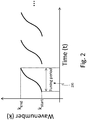
- a sweep trigger 114 triggers the movement of the scanner 118 in the direction of the desired scan to detect a new A-line for each tuning period 200 of the light source 102. That is, for each A-line, the entire bandwidth of the tunable laser 102 is transmitted and detected. After every A-line has been detected for the desired scan, a B-scan image can be formed from the A-lines.
- a sweep trigger 114 can be provided by the light source 102 to move the scanner 118 at the beginning of each tuning period 200, so that each A-line comprises the entire tuning period 200 of the light source 102.
- the k -clock 116 and sweep trigger 114 may be asynchronous, causing an uncertainty as to the starting wavelength of the tuning period for a particular A-line. Such uncertainty affects phase sensitive measurements by introducing depth dependent phase jittering or deviation among the A-lines. This can also result in missampling that causes data point loss. Such missampling, as illustrated in FIG. 3 , may be the result of mechanical or optical jittering during laser sweeping, or because the external linear k -clock varies its frequency rapidly to accommodate the nonlinearity of the wavelength tuning period. For high speed SS-OCT, the sampling clock goes up to a fairly high frequency (e.g., > 100 MHz) and, more importantly, its frequency varies extremely rapidly-about 4x10 13 Hz/s.
- a fairly high frequency e.g., > 100 MHz
- missampled interferogram 304 comprises at least one fewer data point than correctly sampled interferogram 306.
- 3b illustrates point spread functions 314 and 316 for the missampled interferogram 304 and correctly sampled interferogram 306, respectively.
- the baseline noise for the missampled interferogram 304 is roughly 10 dB higher than that of the correctly sampled interferogram 306.
- various techniques may be used correct the starting wavenumber uncertainty discussed above.
- One such technique requires generating a wavenumber reference signal so that detected interferograms can be aligned according to a known wavenumber or wavelength. That is, rather than generating a B-scan by aligning interferograms according to sample numbers as they were detected, the interferograms may be shifted and aligned according to whatever sample number corresponds to the known wavelength or wavenumber of the wavenumber reference signal.
- a second wavenumber reference signal can be used to detect missampling, according to methods discussed below. In short, these methods align interferograms according to one wavenumber reference signal and look for misalignment at other wavenumber reference signals, where misalignment indicates a missampled interferogram.
- a “reference signal” as used herein means a detected interference signal that is attenuated or enhanced beyond the normally detected signal levels of an interferogram.
- One way of generating wavenumber reference signals is by using an optical element such as an optical notch filter.
- One such filter is a Fiber Bragg grating (FBG), a type of distributed Bragg reflector constructed in a short segment of optical fiber that reflects particular wavelengths of light and transmits all others. This effect is achieved by creating a periodic variation in the refractive index of the fiber core, which generates a wavelength specific dielectric mirror.
- FBGs therefore, can be used as an inline optical filter to block certain wavelengths, or in other words, act as a wavenumber-specific reflector for generating a wavenumber reference signal.
- optical notch filters and FBGs are used throughout this description for illustrative purposes for generating wavenumber reference signals.
- FBGs and optical notch filters are but a single technique, and should not be seen as a limiting embodiment.
- a bandpass filter may be used, wherein the upper and lower frequencies of the bandpass filter each represent wavenumber reference signals at the corresponding wavenumbers.
- an exemplary filter to use in the present invention it is important to look for filters that can generate stable and high resolution reference signals. Specifically, for ophthalmic OCT applications, the spectral resolution often goes below 0.1 nm to provide sufficient imaging range. Therefore, it is desirable for the filter used to generate reference signals to have substantial transmission ratio change within 0.1 nm, so that the reference signal has resolution that is better than 0.1 nm. For other OCT applications, a lower or higher resolution may be applicable.
- FIG. 4 illustrates one embodiment of an SS-OCT imaging system of the present invention utilizing two filters to generate wavenumber reference signals.
- the OCT system of FIG. 4 comprises many of the same elements discussed in relation to FIG. 1 , such as the light source 102, reference mirror 108, subject or object 100, optical adapter or beam splitter 112, k -clock 116, data acquisition device (DAQ) 122 sweep trigger 114, and scanner 118.
- FIG. 4 adds two optical notch filters 400, 402, corresponding to two wavenumbers, to the detection arm 404 of the OCT system. In such an embodiment, light recombined in the detection arm passes through each filter in series.
- optical notch filters 400, 402 are shown as distinct elements, they may exist in a single filter device as a double notch filter. In other embodiments, a single bandpass filter may be used, as well as other devices or filters known to those skilled in the art to generate a wavenumber reference signal by attenuating or enhancing the signal detected at known wavelengths.
- the example embodiment of FIG. 4 shows both optical notch filters 400, 402 being located in the detection arm 404, it should be appreciated that the optical notch filters 400, 402 can be placed anywhere in the optical paths of the OCT system.
- the detection arm 404 may be split into two parallel light paths.
- the optical notch filters 402, 404 may be placed in parallel rather than in series.
- the optical notch filters 402, 404 may be placed in the sample arm 104, reference arm 106, or between the light source 102 and optical adapter 112, in a similar fashion to those embodiments discussed with respect to the detection arm 404.
- the optical notch filters 402, 404 may be placed in the same arm or in different arms of the OCT system.
- FIG. 5 illustrates one possible method for detecting missampled interferograms using reference signals.
- a graphical depiction of some of the steps of FIG. 5 is shown in FIG. 6 .
- interferograms 600 representing each A-line of a scan are aligned according to one of the wavenumber reference signals 604, as shown in exploded view 602, so as to remove any starting wavenumber uncertainty.
- the interferograms 600 are analyzed with respect to at least one other wavenumber reference signal, as shown in exploded view 606.
- any wavenumber reference signal may be used for removing uncertainty and any other wavenumber reference signal may be used to detect missampling.
- the other wavenumber reference signal for the missampled interferograms 608 will not align with the wavenumber reference signal of properly sampled interferograms 610.
- misaligned interferograms are identified as missampled.
- the interferogram may be desirable to discard the interferogram or try to correct the interferogram. If the interferogram is discarded, a B-scan may still be generated, however. In one embodiment, the B-scan can simply be compiled without the missampled interferogram. In other embodiments, the missampled interferogram can be replaced by an identical copy of the interferograms directly before and after it, or by interpolation techniques or averaging of the interferograms before and after it. Rather than replacing the entire interferogram, it may also be possible to actually correct the lone missampled portion of the missampled interferogram. Again, a number of interpolation or interpolation-like techniques are envisioned.
- an interpolation technique could be used to recreate the missing data point(s).
- An interpolation technique is to average the data points directly before and after where the missed data point should belong, then insert a data point with the averaged value at the missampled location.
- Another technique relies on averaging the interferograms directly before and after the missampled interferogram at the data point corresponding to the missampled data point. Another technique might involve merely duplicating the data point from a neighboring interferogram. It should be noted that any interpolation technique or any technique for replacing a missing data point known to those skilled in the art could be used.
- the optical notch filters are optimized to minimize the number of data points affected by each optical notch filter.
- the wavenumber reference signals contain a set of data points that are affected due to the blocking of light by the optical notch filters. Some of the affected data points may be simply distorted, while others may be saturated. These affected data points, especially those saturated ones, inevitably compromise the signal integrity and thus cause undesirable artifacts in the OCT image.
- optimizing the bandwidth of an optical notch filter at least two factors should be taken in to account. First, when the bandwidth of the wavenumber reference signal is much smaller than the resolution of an OCT system, it may not be "visible" to the OCT system and, thus, the wavenumber reference signal is of no use.
- the resolution of the OCT system establishes a lower boundary for the bandwidth of the wavenumber reference signal.
- a larger bandwidth of the wavenumber reference signal will result in more data points being affected. Therefore, the upper boundary for the bandwidth of the wavenumber reference signal should be as small as possible to minimize the number of affected data points.
- the optimal bandwidth for the optical notch filters is between ⁇ k and 2 ⁇ k, where ⁇ k is the wavenumber resolution of the SS-OCT system. Such optimal bandwidth provides the wavenumber reference signal with at least one data point.
- data points affected by the optical notch filters are compensated for, and restored, to decrease the effect each optical notch filter has on the quality of the image.
- saturated data points carry no interference signal
- non-saturated data points contain an interference signal that can be restored.
- This compensation method benefits from the optimization of the optical notch filter bandwidth, as previously discussed, to minimize the number of data points affected in that the approximation is more accurate.
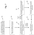
- interferograms are first obtained 700 by laterally scanning a highly heterogeneous sample, e.g. biological tissues, so that the sum of I ( k,n ) approximates the spectrum profile.
- each interferogram is aligned and those with missampling are removed or corrected. This step may be performed by the method described above with respect to FIGS. 5 and 6 or similar techniques known to those skilled in the art.
- common mode noise is removed 704 from the remaining interferograms by subtracting the mean or median value of all interferograms along the lateral scan from each interferogram.
- the spectrum profile is determined by summing the absolute value of the interferogram along the lateral scan, where n is the index of interferograms along the lateral scan, according to the equation A ( k ) ⁇ ⁇ n
- step 708 is the calculation of ⁇ ( k ) for the OCT system.
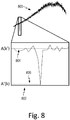
- An approximated spectrum profile can be generated by finding the sum of the absolute value of all interferograms along the lateral scan. Due to its narrow bandwidth, the spectrum profile around the wavenumber reference signal can be considered as a flat line. Therefore, ⁇ n
- the spectrum profile A ( k ) is generated by finding the sum of the absolute value of each interferogram along the lateral scan.
- the graphical meanings of A ( k' ) 802 and A' ( k ) are illustrated in FIG. 8 , which shows a graph of A ( k ) 800 comprising a wavenumber reference signal shown in exploded view 802.
- the order of the steps in the above method may be varied depending on the embodiment. For example, the system may first be calibrated according to steps 706 and 708 before obtaining interferograms for the current scan, presuming the system previously generated a set of interferograms to be used in calibration. Additionally, affected data points may be restored prior to identifying missampled interferograms.
- the removal of common mode noise according to step 704 and the restoration of affected data points according to step 710 may both be performed on a single interferogram before proceeding to the next interferogram in the scan, or could individually be performed on every interferogram before proceeding to the next step.
- other variations to the steps or order of the steps in the method known to those skilled in the art are within the scope of the presented method.
Landscapes
- Physics & Mathematics (AREA)
- General Physics & Mathematics (AREA)
- Health & Medical Sciences (AREA)
- General Health & Medical Sciences (AREA)
- Nuclear Medicine, Radiotherapy & Molecular Imaging (AREA)
- Radiology & Medical Imaging (AREA)
- Engineering & Computer Science (AREA)
- Automation & Control Theory (AREA)
- Optics & Photonics (AREA)
- Investigating Or Analysing Materials By Optical Means (AREA)
- Eye Examination Apparatus (AREA)
Claims (14)
- Verfahren zur Fourier Domain optischen Kohärenztomografie, FD-OCT,-Bildgebung, umfassend die Schritte:Erhalten einer Vielzahl von Interferogrammen;Bereitstellen von mindestens zwei Wellenzahlreferenzsignalen bei unterschiedlichen Wellenzahlen in jedem der Vielzahl von Interferogrammen, wobei die Wellenzahlreferenzsignale Abschnitte der Interferogramme sind, die über das normalerweise detektierte Signalniveau bei den unterschiedlichen Wellenzahlen abgeschwächt oder verstärkt sind;Ausrichten (500) von jedem der Vielzahl von Interferogrammen gemäß einem der mindestens zwei Wellenzahlreferenzsignalen; und
für jedes der Vielzahl von Interferogrammen Identifizieren (504) ob ein Interferogram fehlabgetastet ist durch Benutzen eines anderen der mindestens zwei Wellenzahlreferenzsignalen. - Verfahren nach Anspruch 1, ferner umfassend:Bereitstellen mindestens eines optischen Elements an ein OCT-Bildgebungssystem, das zum Generieren der mindestens zwei Wellenzahlreferenzsignale konfiguriert ist;Generieren von Licht aus einer Lichtquelle (102);Verwenden eines optischen Detektors (110), um die Vielzahl von Interferogrammen zu erhalten, die durch das Licht generiert werden; undErmitteln einer Abtastungszahl, die einem anderen der mindestens zwei Wellenzahlreferenzsignale entspricht, für jedes der Vielzahl von Interferogrammen.
- Verfahren nach einem der vorhergehenden Ansprüche, ferner umfassend die Schritte:Erhalten (706) eines Spektrumprofils durch Summieren des Absolutwerts von Signalen des Interferogramms;Berechnen (708) eines Transmissionsverhältnisses an der Wellenzahl, die mindestens jedem der mindestens zwei Wellenzahlreferenzsignale entspricht; undfür jedes der Vielzahl von Interferogrammen, Neuberechnen des Interferogramms an der Wellenzahl, die jedem der mindestens zwei Wellenzahlreferenzsignale entspricht, indem das Interferogramm an der Wellenzahl durch das Transmissionsverhältnis geteilt wird.
- Verfahren nach einem der vorhergehenden Ansprüche, wobei für jedes der Vielzahl von Interferogrammen das Identifizieren eines Interferogramms als fehlabgetastet darauf basiert, ob sich ein anderes der mindestens zwei Referenzsignale nicht mit einem entsprechenden Referenzsignal in einer statistisch signifikanten Anzahl der Vielzahl von Interferogrammen ausrichtet, wobei insbesondere die statistisch signifikante Anzahl der Vielzahl von Interferogrammen ein überwiegender Teil der Vielzahl von Interferogrammen ist.
- Verfahren nach einem der vorhergehenden Ansprüche, ferner umfassend den Schritt des Korrigierens, Ersetzens oder Verwerfens der identifizierten Interferogramme.
- Verfahren nach einem der vorhergehenden Ansprüche, wobei die mindestens zwei Wellenzahlreferenzsignale durch mindestens einen optischen Notchfilter (400, 402) generiert werden, wobei insbesondere der mindestens eine optische Notchfilter mindestens ein Faser-Bragg-Gitter (FBG) umfasst.
- Verfahren nach Anspruch 6, wobei der mindestens eine optische Notchfilter (400, 402) eine Bandbreite zwischen dem ein- und zweifachen einer Wellenzahlauflösung des OCT-Bildgebungssystems hat und/oder vor einem balancierten Detektor in dem OCT-Bildgebungssystem positioniert ist.
- Verfahren nach einem der Ansprüche 6 oder 7, wobei einer der mindestens einen optischen Notchfilter (400, 402) eine Mittenwellenzahl in einer Hälfte der Wellenzahlen hat, die mit einer Lichtquelle des OCT-Bildgebungssystems assoziiert sind, und ein anderer der mindestens einen optischen Notchfilter eine Mittenwellenzahl in der anderen Hälfte der Wellenzahlen hat, die mit der Lichtquelle des OCT-Bildgebungssystems assoziiert sind.
- Fourier-Domain-Optischen-Kohärenztomografie, FD-OCT,-Bildgebungssystem, umfassend
eine Lichtquelle (102);
einen Referenzarm (106);
einen Abtastungsarm (104);
einen Detektierungsarm (404); und
mindestens ein optisches Element, das zum Generieren von mindestens zwei Wellenzahlreferenzsignalen bei unterschiedlichen Wellenzahlen in jedem der Vielzahl von Interferogrammen konfiguriert ist, wobei die Wellenzahlreferenzsignale Abschnitte der Interferogramme sind, die über das normalerweise detektierte Signalniveau bei den unterschiedlichen Wellenzahlen abgeschwächt oder verstärkt sind; und
einen Prozessor, der konfiguriert ist zum:
Erhalten einer Vielzahl von Interferogrammen;
Ausrichten (500) von jedem der Vielzahl von Interferogrammen gemäß einem der mindestens zwei Wellenzahlreferenzsignale; und
für jedes der Vielzahl von Interferogrammen, Identifizieren (504) ob ein Interferograms fehlabgetastet ist durch Benutzen eines anderen der mindestens zwei Wellenzahlreferenzsignalen. - OCT-Bildgebungssystem nach Anspruch 9, wobei das mindestens eine optische Element mindestens einen optischen Notchfilter (400, 402) umfasst, wobei insbesondere der mindestens eine optische Notchfilter mindestens ein Faser-Bragg-Gitter (FBG) umfasst.
- OCT-Bildgebungssystem nach Anspruch 10, wobei einer der mindestens einen optischen Notchfilter (400, 402) eine Mittenwellenzahl in einer Hälfte der Wellenzahlen hat, die mit einer Lichtquelle des OCT-Bildgebungssystems assoziiert sind, und ein anderer der mindestens einen optischen Notchfilter eine Mittenwellenzahl in der anderen Hälfte der Wellenzahlen hat, die mit der Lichtquelle des OCT-Bildgebungssystems assoziiert sind.
- OCT-Bildgebungssystem nach einem der Ansprüche 9 bis 11, wobei ein Interferogramms als fehlabgetastet identifiziert wird, wenn ein anderes der mindestens zwei Wellenzahlreferenzsignale sich nicht mit einem entsprechenden Wellenzahlreferenzsignal in einer statistisch signifikanten Zahl der Vielzahl von Interferogrammen ausrichtet.
- OCT-Bildgebungssystem nach einem der Ansprüche 9 bis 12, wobei das mindestens eine optische Element in dem Detektierungsarm (404) positioniert ist.
- OCT-Bildgebungssystem nach einem der Ansprüche 9 bis 13, wobei der Prozessor ferner konfiguriert ist, um die identifizierten Interferogramme zu korrigieren, zu ersetzen oder zu verwerfen, und/oder wobei der Prozessor ferner konfiguriert ist zum:Erhalten eines Spektrumprofils durch Summieren der Absolutwerte der Signale des Interferogramms;Berechnen eines Transmissionsverhältnisses an der Wellenzahl, die jedem der mindestens zwei Wellenzahlreferenzsignalen entspricht; undfür jedes der Vielzahl von Interferogrammen, Neuberechnen des Interferogramms an der Wellenzahl, die jedem der mindestens zwei Wellenzahlreferenzsignale entspricht, indem das Interferogramm an der Wellenzahl durch das Transmissionsverhältnis geteilt wird.
Priority Applications (1)
| Application Number | Priority Date | Filing Date | Title |
|---|---|---|---|
| DE14169770.6T DE14169770T1 (de) | 2014-01-23 | 2014-05-26 | Nachweis von falsch abgetasteten Interferogrammen in der optischen Frequenzbereich Kohärenztomographie mit einem Wellenzahl-Taktgeber |
Applications Claiming Priority (1)
| Application Number | Priority Date | Filing Date | Title |
|---|---|---|---|
| US14/161,796 US10317189B2 (en) | 2014-01-23 | 2014-01-23 | Detection of missampled interferograms in frequency domain OCT with a k-clock |
Publications (2)
| Publication Number | Publication Date |
|---|---|
| EP2899494A1 EP2899494A1 (de) | 2015-07-29 |
| EP2899494B1 true EP2899494B1 (de) | 2018-09-12 |
Family
ID=50771437
Family Applications (1)
| Application Number | Title | Priority Date | Filing Date |
|---|---|---|---|
| EP14169770.6A Active EP2899494B1 (de) | 2014-01-23 | 2014-05-26 | Nachweis von falsch abgetasteten Interferogrammen in der optischen Frequenzbereich Kohärenztomographie mit einem Wellenzahl-Taktgeber |
Country Status (4)
| Country | Link |
|---|---|
| US (1) | US10317189B2 (de) |
| EP (1) | EP2899494B1 (de) |
| JP (1) | JP5869616B2 (de) |
| DE (1) | DE14169770T1 (de) |
Families Citing this family (5)
| Publication number | Priority date | Publication date | Assignee | Title |
|---|---|---|---|---|
| JP6685673B2 (ja) * | 2015-05-01 | 2020-04-22 | キヤノン株式会社 | 撮像装置 |
| EP3362787B1 (de) | 2015-10-16 | 2025-05-14 | Audioptics Medical Incorporated | Systeme und verfahren zur optischen kohärenztomographischen vibrographie mit gewobbelter quelle |
| US10788310B2 (en) | 2016-02-24 | 2020-09-29 | Kabushiki Kaisha Topcon | Methods and apparatus for phase stabilized swept-source optical coherence tomography (SS-OCT) including rescaling and dynamic range enhancement |
| US10687738B2 (en) * | 2017-02-24 | 2020-06-23 | Audioptics Medical Incorporated | Systems and methods for performing phase-sensitive acoustic vibrations using optical coherence tomography |
| JP7261448B2 (ja) * | 2018-12-28 | 2023-04-20 | 株式会社トーメーコーポレーション | 眼科装置 |
Family Cites Families (39)
| Publication number | Priority date | Publication date | Assignee | Title |
|---|---|---|---|---|
| US5991653A (en) * | 1995-03-14 | 1999-11-23 | Board Of Regents, The University Of Texas System | Near-infrared raman spectroscopy for in vitro and in vivo detection of cervical precancers |
| JP3459327B2 (ja) * | 1996-06-17 | 2003-10-20 | 理化学研究所 | 積層構造体の層厚および屈折率の測定方法およびその測定装置 |
| US7365858B2 (en) * | 2001-12-18 | 2008-04-29 | Massachusetts Institute Of Technology | Systems and methods for phase measurements |
| US7796243B2 (en) * | 2004-06-09 | 2010-09-14 | National Research Council Of Canada | Detection and monitoring of changes in mineralized tissues or calcified deposits by optical coherence tomography and Raman spectroscopy |
| US8315282B2 (en) * | 2005-01-20 | 2012-11-20 | Massachusetts Institute Of Technology | Fourier domain mode locking: method and apparatus for control and improved performance |
| ES2669059T3 (es) | 2005-07-28 | 2018-05-23 | Bioptigen, Inc. | Sistema de formación de imagen de tomografía de coherencia óptica en el dominio de la frecuencia |
| ATE484727T1 (de) * | 2005-08-09 | 2010-10-15 | Gen Hospital Corp | Gerät und verfahren zur durchführung von polarisationsbasierter quadraturdemodulation bei optischer kohärenztomographie |
| US7742174B2 (en) * | 2006-07-17 | 2010-06-22 | Bioptigen, Inc. | Methods, systems and computer program products for removing undesired artifacts in fourier domain optical coherence tomography (FDOCT) systems using continuous phase modulation and related phase modulators |
| US9867530B2 (en) * | 2006-08-14 | 2018-01-16 | Volcano Corporation | Telescopic side port catheter device with imaging system and method for accessing side branch occlusions |
| ES3007239T3 (en) | 2007-01-10 | 2025-03-19 | Lightlab Imaging Inc | Methods and apparatus for swept-source optical coherence tomography |
| US9596993B2 (en) * | 2007-07-12 | 2017-03-21 | Volcano Corporation | Automatic calibration systems and methods of use |
| WO2009009799A1 (en) * | 2007-07-12 | 2009-01-15 | Volcano Corporation | Catheter for in vivo imaging |
| US8120781B2 (en) * | 2008-11-26 | 2012-02-21 | Zygo Corporation | Interferometric systems and methods featuring spectral analysis of unevenly sampled data |
| JP6101078B2 (ja) | 2009-05-28 | 2017-03-29 | アビンガー・インコーポレイテッドAvinger, Inc. | バイオイメージングのための光コヒーレンストモグラフィ |
| US8285368B2 (en) * | 2009-07-10 | 2012-10-09 | The Regents Of The University Of California | Endoscopic long range fourier domain optical coherence tomography (LR-FD-OCT) |
| WO2012018832A2 (en) * | 2010-08-02 | 2012-02-09 | The Johns Hopkins University | Automatic calibration of fourier-domain optical coherence tomography systems |
| CA2836790C (en) | 2011-05-31 | 2019-04-23 | Desmond Adler | Multimodal imaging system, apparatus, and methods |
| US8564788B2 (en) * | 2011-07-26 | 2013-10-22 | Kabushiki Kaisha Topcon | Optical imaging method and optical imaging apparatus |
| WO2013033592A1 (en) * | 2011-08-31 | 2013-03-07 | Volcano Corporation | Optical-electrical rotary joint and methods of use |
| US9784559B2 (en) * | 2012-03-21 | 2017-10-10 | Ludwig-Maximilians-Universität München | Swept source OCT system and method with phase-locked detection |
| US9441944B2 (en) * | 2012-05-16 | 2016-09-13 | Axsun Technologies Llc | Regenerative mode locked laser swept source for OCT medical imaging |
| US10539731B2 (en) * | 2012-06-07 | 2020-01-21 | Poinare Systems, Inc. | Grin lens and methods of making the same |
| CN107252302B (zh) * | 2012-07-27 | 2020-08-18 | 统雷有限公司 | 敏捷成像系统 |
| US9292918B2 (en) * | 2012-10-05 | 2016-03-22 | Volcano Corporation | Methods and systems for transforming luminal images |
| US9367965B2 (en) * | 2012-10-05 | 2016-06-14 | Volcano Corporation | Systems and methods for generating images of tissue |
| US9307926B2 (en) * | 2012-10-05 | 2016-04-12 | Volcano Corporation | Automatic stent detection |
| WO2014055880A2 (en) * | 2012-10-05 | 2014-04-10 | David Welford | Systems and methods for amplifying light |
| US9324141B2 (en) * | 2012-10-05 | 2016-04-26 | Volcano Corporation | Removal of A-scan streaking artifact |
| US9286673B2 (en) * | 2012-10-05 | 2016-03-15 | Volcano Corporation | Systems for correcting distortions in a medical image and methods of use thereof |
| US9858668B2 (en) * | 2012-10-05 | 2018-01-02 | Volcano Corporation | Guidewire artifact removal in images |
| JP2016504589A (ja) * | 2012-12-20 | 2016-02-12 | ナサニエル ジェイ. ケンプ, | 異なる撮像モード間で再構成可能な光コヒーレンストモグラフィシステム |
| CA2895770A1 (en) * | 2012-12-20 | 2014-07-24 | Jeremy Stigall | Locating intravascular images |
| US9612105B2 (en) * | 2012-12-21 | 2017-04-04 | Volcano Corporation | Polarization sensitive optical coherence tomography system |
| EP2936626A4 (de) * | 2012-12-21 | 2016-08-17 | David Welford | Systeme und verfahren zur verengung einer wellenlängenlichtemission |
| US9486143B2 (en) * | 2012-12-21 | 2016-11-08 | Volcano Corporation | Intravascular forward imaging device |
| JP6243453B2 (ja) * | 2013-03-07 | 2017-12-06 | ボルケーノ コーポレイション | 血管内画像におけるマルチモーダルセグメンテーション |
| US9301687B2 (en) * | 2013-03-13 | 2016-04-05 | Volcano Corporation | System and method for OCT depth calibration |
| WO2015179224A1 (en) * | 2014-05-23 | 2015-11-26 | University Of Massachusetts | Fourier domain terahertz coherence tomography (tct) |
| WO2016054079A1 (en) * | 2014-09-29 | 2016-04-07 | Zyomed Corp. | Systems and methods for blood glucose and other analyte detection and measurement using collision computing |
-
2014
- 2014-01-23 US US14/161,796 patent/US10317189B2/en active Active
- 2014-05-12 JP JP2014098305A patent/JP5869616B2/ja active Active
- 2014-05-26 EP EP14169770.6A patent/EP2899494B1/de active Active
- 2014-05-26 DE DE14169770.6T patent/DE14169770T1/de active Pending
Non-Patent Citations (1)
| Title |
|---|
| None * |
Also Published As
| Publication number | Publication date |
|---|---|
| JP5869616B2 (ja) | 2016-02-24 |
| US10317189B2 (en) | 2019-06-11 |
| EP2899494A1 (de) | 2015-07-29 |
| DE14169770T1 (de) | 2015-09-17 |
| JP2015138024A (ja) | 2015-07-30 |
| US20150204651A1 (en) | 2015-07-23 |
Similar Documents
| Publication | Publication Date | Title |
|---|---|---|
| Izatt et al. | Theory of optical coherence tomography | |
| US9354038B2 (en) | Swept source optical coherence tomography and method for stabilizing phase thereof | |
| US10502544B2 (en) | Efficient sampling of optical coherence tomography data for explicit ranging over extended depth | |
| US8049900B2 (en) | Apparatus and methods for uniform frequency sample clocking | |
| US9060689B2 (en) | Apparatus, method and system for performing phase-resolved optical frequency domain imaging | |
| JP6360065B2 (ja) | スペクトル領域干渉法における信号処理方法および装置、並びにスペクトル領域光コヒーレンストモグラフィの方法および装置 | |
| US8921767B2 (en) | Automatic calibration of fourier-domain optical coherence tomography systems | |
| JP5938926B2 (ja) | 光断層像撮影装置及びノイズ除去方法 | |
| JP6465557B2 (ja) | 断層撮影装置 | |
| US9492077B2 (en) | Optimized device for swept source optical coherence domain reflectometry and tomography | |
| US20140268038A1 (en) | Systems and methods for variable depth optical coherence tomography imaging | |
| JP2013181790A (ja) | 周波数走査型oct用サンプリングクロック発生装置の使用方法、周波数走査型oct用サンプリングクロック発生装置 | |
| US10317189B2 (en) | Detection of missampled interferograms in frequency domain OCT with a k-clock | |
| Poddar et al. | In vitro 3D anterior segment imaging in lamb eye with extended depth range swept source optical coherence tomography | |
| US10760893B2 (en) | Apparatus and method for processing the signal in master slave interferometry and apparatus and method for master slave optical coherence tomography with any number of sampled depths | |
| Ksenofontov et al. | Numerical method for axial motion artifact correction in retinal spectral-domain optical coherence tomography | |
| US9157727B2 (en) | Image measuring method and image measuring apparatus | |
| JP6214020B2 (ja) | 光断層イメージング法、その装置およびプログラム | |
| Jung et al. | Simple spectral calibration method and its application using an index array for swept source optical coherence tomography | |
| Wang et al. | Full-field swept source master-slave optical coherence tomography | |
| JP2019063044A (ja) | Oct装置、およびoct装置制御プログラム | |
| Amjadi et al. | Developing a new dimension for Fourier domain optical coherence tomography images by simultaneous measurement of the refractive index and thickness | |
| Thakur et al. | Computational framework for combining multiple swept-sources for high-resolution in-vivo optical coherence tomography | |
| Zhang et al. | Improving a Low Axial Resolution Due to Improper Wavelength Calibration in Spectral-Domain Optical Coherence Tomography | |
| Lopera | COMPUTATIONAL ABERRATION CORRECTION IN OPTICAL COHERENCE TOMOGRAPHY WITH PHASE-UNSTABLE SYSTEMS |
Legal Events
| Date | Code | Title | Description |
|---|---|---|---|
| PUAI | Public reference made under article 153(3) epc to a published international application that has entered the european phase |
Free format text: ORIGINAL CODE: 0009012 |
|
| 17P | Request for examination filed |
Effective date: 20140526 |
|
| AK | Designated contracting states |
Kind code of ref document: A1 Designated state(s): AL AT BE BG CH CY CZ DE DK EE ES FI FR GB GR HR HU IE IS IT LI LT LU LV MC MK MT NL NO PL PT RO RS SE SI SK SM TR |
|
| AX | Request for extension of the european patent |
Extension state: BA ME |
|
| RIN1 | Information on inventor provided before grant (corrected) |
Inventor name: CHAN, KINPUI Inventor name: YUAN, ZHIJIA Inventor name: REISMAN, CHARLES A. Inventor name: WANG, ZHENGUO |
|
| REG | Reference to a national code |
Ref country code: FR Ref legal event code: EL |
|
| REG | Reference to a national code |
Ref country code: DE Ref legal event code: R210 Ref document number: 602014032139 Country of ref document: DE Ref country code: DE Ref legal event code: R210 |
|
| RBV | Designated contracting states (corrected) |
Designated state(s): AL AT BE BG CH CY CZ DE DK EE ES FI FR GB GR HR HU IE IS IT LI LT LU LV MC MK MT NL NO PL PT RO RS SE SI SK SM TR |
|
| STAA | Information on the status of an ep patent application or granted ep patent |
Free format text: STATUS: EXAMINATION IS IN PROGRESS |
|
| 17Q | First examination report despatched |
Effective date: 20171025 |
|
| GRAP | Despatch of communication of intention to grant a patent |
Free format text: ORIGINAL CODE: EPIDOSNIGR1 |
|
| STAA | Information on the status of an ep patent application or granted ep patent |
Free format text: STATUS: GRANT OF PATENT IS INTENDED |
|
| INTG | Intention to grant announced |
Effective date: 20180403 |
|
| GRAJ | Information related to disapproval of communication of intention to grant by the applicant or resumption of examination proceedings by the epo deleted |
Free format text: ORIGINAL CODE: EPIDOSDIGR1 |
|
| STAA | Information on the status of an ep patent application or granted ep patent |
Free format text: STATUS: EXAMINATION IS IN PROGRESS |
|
| GRAR | Information related to intention to grant a patent recorded |
Free format text: ORIGINAL CODE: EPIDOSNIGR71 |
|
| GRAS | Grant fee paid |
Free format text: ORIGINAL CODE: EPIDOSNIGR3 |
|
| STAA | Information on the status of an ep patent application or granted ep patent |
Free format text: STATUS: GRANT OF PATENT IS INTENDED |
|
| INTC | Intention to grant announced (deleted) | ||
| GRAA | (expected) grant |
Free format text: ORIGINAL CODE: 0009210 |
|
| STAA | Information on the status of an ep patent application or granted ep patent |
Free format text: STATUS: THE PATENT HAS BEEN GRANTED |
|
| INTG | Intention to grant announced |
Effective date: 20180706 |
|
| REG | Reference to a national code |
Ref country code: DE Ref legal event code: R082 Country of ref document: DE Ref country code: DE Ref legal event code: R082 Ref document number: 602014032139 Country of ref document: DE Representative=s name: LAVOIX MUNICH, DE |
|
| AK | Designated contracting states |
Kind code of ref document: B1 Designated state(s): AL AT BE BG CH CY CZ DE DK EE ES FI FR GB GR HR HU IE IS IT LI LT LU LV MC MK MT NL NO PL PT RO RS SE SI SK SM TR |
|
| REG | Reference to a national code |
Ref country code: GB Ref legal event code: FG4D |
|
| REG | Reference to a national code |
Ref country code: CH Ref legal event code: EP |
|
| REG | Reference to a national code |
Ref country code: DE Ref legal event code: R082 Ref document number: 602014032139 Country of ref document: DE Representative=s name: LAVOIX MUNICH, DE |
|
| REG | Reference to a national code |
Ref country code: DE Ref legal event code: R082 Ref document number: 602014032139 Country of ref document: DE Representative=s name: LAVOIX MUNICH, DE |
|
| REG | Reference to a national code |
Ref country code: IE Ref legal event code: FG4D |
|
| REG | Reference to a national code |
Ref country code: DE Ref legal event code: R096 Ref document number: 602014032139 Country of ref document: DE |
|
| REG | Reference to a national code |
Ref country code: AT Ref legal event code: REF Ref document number: 1041134 Country of ref document: AT Kind code of ref document: T Effective date: 20181015 |
|
| REG | Reference to a national code |
Ref country code: NL Ref legal event code: MP Effective date: 20180912 |
|
| REG | Reference to a national code |
Ref country code: LT Ref legal event code: MG4D |
|
| PG25 | Lapsed in a contracting state [announced via postgrant information from national office to epo] |
Ref country code: GR Free format text: LAPSE BECAUSE OF FAILURE TO SUBMIT A TRANSLATION OF THE DESCRIPTION OR TO PAY THE FEE WITHIN THE PRESCRIBED TIME-LIMIT Effective date: 20181213 Ref country code: NO Free format text: LAPSE BECAUSE OF FAILURE TO SUBMIT A TRANSLATION OF THE DESCRIPTION OR TO PAY THE FEE WITHIN THE PRESCRIBED TIME-LIMIT Effective date: 20181212 Ref country code: FI Free format text: LAPSE BECAUSE OF FAILURE TO SUBMIT A TRANSLATION OF THE DESCRIPTION OR TO PAY THE FEE WITHIN THE PRESCRIBED TIME-LIMIT Effective date: 20180912 Ref country code: LT Free format text: LAPSE BECAUSE OF FAILURE TO SUBMIT A TRANSLATION OF THE DESCRIPTION OR TO PAY THE FEE WITHIN THE PRESCRIBED TIME-LIMIT Effective date: 20180912 Ref country code: RS Free format text: LAPSE BECAUSE OF FAILURE TO SUBMIT A TRANSLATION OF THE DESCRIPTION OR TO PAY THE FEE WITHIN THE PRESCRIBED TIME-LIMIT Effective date: 20180912 Ref country code: BG Free format text: LAPSE BECAUSE OF FAILURE TO SUBMIT A TRANSLATION OF THE DESCRIPTION OR TO PAY THE FEE WITHIN THE PRESCRIBED TIME-LIMIT Effective date: 20181212 Ref country code: SE Free format text: LAPSE BECAUSE OF FAILURE TO SUBMIT A TRANSLATION OF THE DESCRIPTION OR TO PAY THE FEE WITHIN THE PRESCRIBED TIME-LIMIT Effective date: 20180912 |
|
| PG25 | Lapsed in a contracting state [announced via postgrant information from national office to epo] |
Ref country code: LV Free format text: LAPSE BECAUSE OF FAILURE TO SUBMIT A TRANSLATION OF THE DESCRIPTION OR TO PAY THE FEE WITHIN THE PRESCRIBED TIME-LIMIT Effective date: 20180912 Ref country code: AL Free format text: LAPSE BECAUSE OF FAILURE TO SUBMIT A TRANSLATION OF THE DESCRIPTION OR TO PAY THE FEE WITHIN THE PRESCRIBED TIME-LIMIT Effective date: 20180912 Ref country code: HR Free format text: LAPSE BECAUSE OF FAILURE TO SUBMIT A TRANSLATION OF THE DESCRIPTION OR TO PAY THE FEE WITHIN THE PRESCRIBED TIME-LIMIT Effective date: 20180912 |
|
| REG | Reference to a national code |
Ref country code: AT Ref legal event code: MK05 Ref document number: 1041134 Country of ref document: AT Kind code of ref document: T Effective date: 20180912 |
|
| PG25 | Lapsed in a contracting state [announced via postgrant information from national office to epo] |
Ref country code: AT Free format text: LAPSE BECAUSE OF FAILURE TO SUBMIT A TRANSLATION OF THE DESCRIPTION OR TO PAY THE FEE WITHIN THE PRESCRIBED TIME-LIMIT Effective date: 20180912 Ref country code: NL Free format text: LAPSE BECAUSE OF FAILURE TO SUBMIT A TRANSLATION OF THE DESCRIPTION OR TO PAY THE FEE WITHIN THE PRESCRIBED TIME-LIMIT Effective date: 20180912 Ref country code: ES Free format text: LAPSE BECAUSE OF FAILURE TO SUBMIT A TRANSLATION OF THE DESCRIPTION OR TO PAY THE FEE WITHIN THE PRESCRIBED TIME-LIMIT Effective date: 20180912 Ref country code: IS Free format text: LAPSE BECAUSE OF FAILURE TO SUBMIT A TRANSLATION OF THE DESCRIPTION OR TO PAY THE FEE WITHIN THE PRESCRIBED TIME-LIMIT Effective date: 20190112 Ref country code: PL Free format text: LAPSE BECAUSE OF FAILURE TO SUBMIT A TRANSLATION OF THE DESCRIPTION OR TO PAY THE FEE WITHIN THE PRESCRIBED TIME-LIMIT Effective date: 20180912 Ref country code: CZ Free format text: LAPSE BECAUSE OF FAILURE TO SUBMIT A TRANSLATION OF THE DESCRIPTION OR TO PAY THE FEE WITHIN THE PRESCRIBED TIME-LIMIT Effective date: 20180912 Ref country code: RO Free format text: LAPSE BECAUSE OF FAILURE TO SUBMIT A TRANSLATION OF THE DESCRIPTION OR TO PAY THE FEE WITHIN THE PRESCRIBED TIME-LIMIT Effective date: 20180912 Ref country code: EE Free format text: LAPSE BECAUSE OF FAILURE TO SUBMIT A TRANSLATION OF THE DESCRIPTION OR TO PAY THE FEE WITHIN THE PRESCRIBED TIME-LIMIT Effective date: 20180912 Ref country code: IT Free format text: LAPSE BECAUSE OF FAILURE TO SUBMIT A TRANSLATION OF THE DESCRIPTION OR TO PAY THE FEE WITHIN THE PRESCRIBED TIME-LIMIT Effective date: 20180912 |
|
| PG25 | Lapsed in a contracting state [announced via postgrant information from national office to epo] |
Ref country code: SM Free format text: LAPSE BECAUSE OF FAILURE TO SUBMIT A TRANSLATION OF THE DESCRIPTION OR TO PAY THE FEE WITHIN THE PRESCRIBED TIME-LIMIT Effective date: 20180912 Ref country code: PT Free format text: LAPSE BECAUSE OF FAILURE TO SUBMIT A TRANSLATION OF THE DESCRIPTION OR TO PAY THE FEE WITHIN THE PRESCRIBED TIME-LIMIT Effective date: 20190112 Ref country code: SK Free format text: LAPSE BECAUSE OF FAILURE TO SUBMIT A TRANSLATION OF THE DESCRIPTION OR TO PAY THE FEE WITHIN THE PRESCRIBED TIME-LIMIT Effective date: 20180912 |
|
| REG | Reference to a national code |
Ref country code: DE Ref legal event code: R097 Ref document number: 602014032139 Country of ref document: DE |
|
| PLBE | No opposition filed within time limit |
Free format text: ORIGINAL CODE: 0009261 |
|
| STAA | Information on the status of an ep patent application or granted ep patent |
Free format text: STATUS: NO OPPOSITION FILED WITHIN TIME LIMIT |
|
| PG25 | Lapsed in a contracting state [announced via postgrant information from national office to epo] |
Ref country code: DK Free format text: LAPSE BECAUSE OF FAILURE TO SUBMIT A TRANSLATION OF THE DESCRIPTION OR TO PAY THE FEE WITHIN THE PRESCRIBED TIME-LIMIT Effective date: 20180912 |
|
| 26N | No opposition filed |
Effective date: 20190613 |
|
| PG25 | Lapsed in a contracting state [announced via postgrant information from national office to epo] |
Ref country code: SI Free format text: LAPSE BECAUSE OF FAILURE TO SUBMIT A TRANSLATION OF THE DESCRIPTION OR TO PAY THE FEE WITHIN THE PRESCRIBED TIME-LIMIT Effective date: 20180912 |
|
| REG | Reference to a national code |
Ref country code: CH Ref legal event code: PL |
|
| GBPC | Gb: european patent ceased through non-payment of renewal fee |
Effective date: 20190526 |
|
| PG25 | Lapsed in a contracting state [announced via postgrant information from national office to epo] |
Ref country code: MC Free format text: LAPSE BECAUSE OF FAILURE TO SUBMIT A TRANSLATION OF THE DESCRIPTION OR TO PAY THE FEE WITHIN THE PRESCRIBED TIME-LIMIT Effective date: 20180912 Ref country code: CH Free format text: LAPSE BECAUSE OF NON-PAYMENT OF DUE FEES Effective date: 20190531 Ref country code: LI Free format text: LAPSE BECAUSE OF NON-PAYMENT OF DUE FEES Effective date: 20190531 |
|
| REG | Reference to a national code |
Ref country code: BE Ref legal event code: MM Effective date: 20190531 |
|
| PG25 | Lapsed in a contracting state [announced via postgrant information from national office to epo] |
Ref country code: LU Free format text: LAPSE BECAUSE OF NON-PAYMENT OF DUE FEES Effective date: 20190526 |
|
| PG25 | Lapsed in a contracting state [announced via postgrant information from national office to epo] |
Ref country code: TR Free format text: LAPSE BECAUSE OF FAILURE TO SUBMIT A TRANSLATION OF THE DESCRIPTION OR TO PAY THE FEE WITHIN THE PRESCRIBED TIME-LIMIT Effective date: 20180912 |
|
| PG25 | Lapsed in a contracting state [announced via postgrant information from national office to epo] |
Ref country code: GB Free format text: LAPSE BECAUSE OF NON-PAYMENT OF DUE FEES Effective date: 20190526 Ref country code: IE Free format text: LAPSE BECAUSE OF NON-PAYMENT OF DUE FEES Effective date: 20190526 |
|
| PG25 | Lapsed in a contracting state [announced via postgrant information from national office to epo] |
Ref country code: BE Free format text: LAPSE BECAUSE OF NON-PAYMENT OF DUE FEES Effective date: 20190531 |
|
| PG25 | Lapsed in a contracting state [announced via postgrant information from national office to epo] |
Ref country code: CY Free format text: LAPSE BECAUSE OF FAILURE TO SUBMIT A TRANSLATION OF THE DESCRIPTION OR TO PAY THE FEE WITHIN THE PRESCRIBED TIME-LIMIT Effective date: 20180912 |
|
| PG25 | Lapsed in a contracting state [announced via postgrant information from national office to epo] |
Ref country code: HU Free format text: LAPSE BECAUSE OF FAILURE TO SUBMIT A TRANSLATION OF THE DESCRIPTION OR TO PAY THE FEE WITHIN THE PRESCRIBED TIME-LIMIT; INVALID AB INITIO Effective date: 20140526 Ref country code: MT Free format text: LAPSE BECAUSE OF FAILURE TO SUBMIT A TRANSLATION OF THE DESCRIPTION OR TO PAY THE FEE WITHIN THE PRESCRIBED TIME-LIMIT Effective date: 20180912 |
|
| PG25 | Lapsed in a contracting state [announced via postgrant information from national office to epo] |
Ref country code: MK Free format text: LAPSE BECAUSE OF FAILURE TO SUBMIT A TRANSLATION OF THE DESCRIPTION OR TO PAY THE FEE WITHIN THE PRESCRIBED TIME-LIMIT Effective date: 20180912 |
|
| REG | Reference to a national code |
Ref country code: FR Ref legal event code: PLFP Year of fee payment: 10 |
|
| PGFP | Annual fee paid to national office [announced via postgrant information from national office to epo] |
Ref country code: DE Payment date: 20250402 Year of fee payment: 12 |
|
| PGFP | Annual fee paid to national office [announced via postgrant information from national office to epo] |
Ref country code: FR Payment date: 20250401 Year of fee payment: 12 |