EP2899351B1 - Support bracket for sliding doors with side locking and adjustment and Metal profile - Google Patents
Support bracket for sliding doors with side locking and adjustment and Metal profile Download PDFInfo
- Publication number
- EP2899351B1 EP2899351B1 EP14004424.9A EP14004424A EP2899351B1 EP 2899351 B1 EP2899351 B1 EP 2899351B1 EP 14004424 A EP14004424 A EP 14004424A EP 2899351 B1 EP2899351 B1 EP 2899351B1
- Authority
- EP
- European Patent Office
- Prior art keywords
- slider
- bracket
- profile
- screw
- support bracket
- Prior art date
- Legal status (The legal status is an assumption and is not a legal conclusion. Google has not performed a legal analysis and makes no representation as to the accuracy of the status listed.)
- Active
Links
- 239000002184 metal Substances 0.000 title claims description 9
- 230000000295 complement effect Effects 0.000 claims description 2
- 230000010355 oscillation Effects 0.000 description 4
- 239000000463 material Substances 0.000 description 2
- 230000004048 modification Effects 0.000 description 2
- 238000012986 modification Methods 0.000 description 2
- 238000005192 partition Methods 0.000 description 2
- 239000004677 Nylon Substances 0.000 description 1
- 229910000831 Steel Inorganic materials 0.000 description 1
- 229910000842 Zamak Inorganic materials 0.000 description 1
- 238000010276 construction Methods 0.000 description 1
- 239000011888 foil Substances 0.000 description 1
- 230000002452 interceptive effect Effects 0.000 description 1
- 238000004519 manufacturing process Methods 0.000 description 1
- 229920001778 nylon Polymers 0.000 description 1
- 239000004033 plastic Substances 0.000 description 1
- 238000000926 separation method Methods 0.000 description 1
- 230000000087 stabilizing effect Effects 0.000 description 1
- 239000010959 steel Substances 0.000 description 1
- 229920002994 synthetic fiber Polymers 0.000 description 1
Images


Classifications
-
- E—FIXED CONSTRUCTIONS
- E05—LOCKS; KEYS; WINDOW OR DOOR FITTINGS; SAFES
- E05D—HINGES OR SUSPENSION DEVICES FOR DOORS, WINDOWS OR WINGS
- E05D15/00—Suspension arrangements for wings
- E05D15/06—Suspension arrangements for wings for wings sliding horizontally more or less in their own plane
- E05D15/0621—Details, e.g. suspension or supporting guides
- E05D15/0626—Details, e.g. suspension or supporting guides for wings suspended at the top
- E05D15/0652—Tracks
-
- E—FIXED CONSTRUCTIONS
- E05—LOCKS; KEYS; WINDOW OR DOOR FITTINGS; SAFES
- E05D—HINGES OR SUSPENSION DEVICES FOR DOORS, WINDOWS OR WINGS
- E05D15/00—Suspension arrangements for wings
- E05D15/06—Suspension arrangements for wings for wings sliding horizontally more or less in their own plane
- E05D15/0621—Details, e.g. suspension or supporting guides
- E05D15/0626—Details, e.g. suspension or supporting guides for wings suspended at the top
- E05D15/063—Details, e.g. suspension or supporting guides for wings suspended at the top on wheels with fixed axis
- E05D15/0634—Details, e.g. suspension or supporting guides for wings suspended at the top on wheels with fixed axis with height adjustment
- E05D15/0639—Details, e.g. suspension or supporting guides for wings suspended at the top on wheels with fixed axis with height adjustment by vertical bolts
-
- F—MECHANICAL ENGINEERING; LIGHTING; HEATING; WEAPONS; BLASTING
- F16—ENGINEERING ELEMENTS AND UNITS; GENERAL MEASURES FOR PRODUCING AND MAINTAINING EFFECTIVE FUNCTIONING OF MACHINES OR INSTALLATIONS; THERMAL INSULATION IN GENERAL
- F16M—FRAMES, CASINGS OR BEDS OF ENGINES, MACHINES OR APPARATUS, NOT SPECIFIC TO ENGINES, MACHINES OR APPARATUS PROVIDED FOR ELSEWHERE; STANDS; SUPPORTS
- F16M13/00—Other supports for positioning apparatus or articles; Means for steadying hand-held apparatus or articles
- F16M13/02—Other supports for positioning apparatus or articles; Means for steadying hand-held apparatus or articles for supporting on, or attaching to, an object, e.g. tree, gate, window-frame, cycle
-
- E—FIXED CONSTRUCTIONS
- E05—LOCKS; KEYS; WINDOW OR DOOR FITTINGS; SAFES
- E05Y—INDEXING SCHEME ASSOCIATED WITH SUBCLASSES E05D AND E05F, RELATING TO CONSTRUCTION ELEMENTS, ELECTRIC CONTROL, POWER SUPPLY, POWER SIGNAL OR TRANSMISSION, USER INTERFACES, MOUNTING OR COUPLING, DETAILS, ACCESSORIES, AUXILIARY OPERATIONS NOT OTHERWISE PROVIDED FOR, APPLICATION THEREOF
- E05Y2201/00—Constructional elements; Accessories therefor
- E05Y2201/60—Suspension or transmission members; Accessories therefor
- E05Y2201/622—Suspension or transmission members elements
- E05Y2201/638—Cams; Ramps
-
- E—FIXED CONSTRUCTIONS
- E05—LOCKS; KEYS; WINDOW OR DOOR FITTINGS; SAFES
- E05Y—INDEXING SCHEME ASSOCIATED WITH SUBCLASSES E05D AND E05F, RELATING TO CONSTRUCTION ELEMENTS, ELECTRIC CONTROL, POWER SUPPLY, POWER SIGNAL OR TRANSMISSION, USER INTERFACES, MOUNTING OR COUPLING, DETAILS, ACCESSORIES, AUXILIARY OPERATIONS NOT OTHERWISE PROVIDED FOR, APPLICATION THEREOF
- E05Y2600/00—Mounting or coupling arrangements for elements provided for in this subclass
- E05Y2600/60—Mounting or coupling members; Accessories therefor
- E05Y2600/628—Profiles; Strips
Definitions
- the present invention relates to a support bracket for sliding doors with side locking and adjustment. More in particular, the present invention relates to a support bracket for sliding doors and partition panels for the separation of rooms, as well as for sliding doors of cabinets.
- the hanging doors and panels which divide environments, as well as the leaves of some types of furniture, are provided with carriages sliding in guide rails attached to the upper part of the frames of the doors or cabinets.
- the height adjustment of these hanging elements is performed by acting on special brackets with spanners or specific tools, which are inserted frontally in the space existing between the sliding rail and the door, panel or leaf.
- This frontal adjustment and subsequent locking in position of the hanging element has significant drawbacks, especially given that for aesthetic or stylistic reasons it is currently demanded that the space between the sliding rail and the hanging element be as small as possible.
- cover veils suitable to shield said rail are no longer accepted, especially for sliding doors.
- Current manufacturing requirements must also be considered, according to which solutions in which the sliding doors can be placed flush with the ceiling or recessed flush with the plasterboard false ceiling are increasingly popular; in these cases too, the space existing between the rail and leaf or door must therefore be as limited in height as possible.
- a device suitable to regulate both in height and in the longitudinal direction a door or leaf connected to a carriage sliding in a rail comprises a box, attached to the sliding door, consisting of a plurality of components connected together and provided, along the inner and outer vertical walls with multiple horizontal, vertical and oblique through cavities. By means of screws and pins which are made to slide in said cavities the movement of the sliding door is achieved to perform the adjustment required.
- WO2011 161707 relates to a system for the height adjustment of a retractable sliding door, which is moved by means of carriages. Said latter are coupled to respective supports by a screw the rotation of which causes the relative movement between said elements and the consequent height adjustment of the door.
- EP 2 243 913 also describes a support for sliding doors with means for height adjustment.
- Such means comprise a threaded element which engages with a worm screw, in turn engaged with a helical gear.
- a threaded element engages with a worm screw, in turn engaged with a helical gear.
- brackets with lateral adjustment i.e. performed starting from an open face of the sliding rail, but in this case too the problem arises of the attachment using tools of said brackets in the upper part adjacent to the rail and the space between the latter and the hanging element thus remains high.
- brackets with lateral adjustment i.e. performed starting from an open face of the sliding rail
- bracket it is possible to perform locking but not lateral adjustment; to achieve the latter it is necessary to remove the door or leaf from the relative bracket. This is, however, on the whole, a rather imprecise adjustment, now rejected by the manufacturers of sliding doors.
- a further drawback which is found in relation to the sliding elements in question concerns the possible recoil incurred at the end stroke and which sometimes determines dangerous oscillations in the vertical direction and a high level of noise.
- the purpose of the present invention is to overcome the aforementioned drawbacks, which are solved with a support bracket and a metal profile comprising the features of claim 1. More in particular, the purpose of the present invention is to provide a support bracket for sliding doors with side locking and adjustment which allows for easy height adjustment and locking of the door or leaf, at the same time significantly reducing the space remaining between the hanging element and the respective sliding rail.
- a further purpose of the invention is to provide a bracket as defined above wherein the height adjustment and subsequent locking of the door or leaf can be achieved with lateral interventions in relation to the sliding rail, without the need however to remove the hanging element from its bracket.
- a no less important purpose of the invention is to provide a support bracket suitable to prevent the recoil which the doors or leaves can suffer at the end of the stroke, thus avoiding both the subsequent oscillations and the noise.
- a further purpose of the invention is to make available to users a support bracket suitable to ensure a high level of resistance and reliability over time, in addition such as to be easily and economically made.
- each bracket in the recess 14" of the profile 14 is preferably achieved by means of a slider 28, typically in synthetic material such as reinforced nylon, consisting of a prismatic body provided with superposed and aligned openings extended horizontally 30 and 32, the latter threaded; said openings 30 and 32 are oriented in alignment with the longitudinal axis of the body 12.
- a slider 28 typically in synthetic material such as reinforced nylon, consisting of a prismatic body provided with superposed and aligned openings extended horizontally 30 and 32, the latter threaded; said openings 30 and 32 are oriented in alignment with the longitudinal axis of the body 12.
- opposite lugs with an inclined profile 34 project, designed to abut and slide along corresponding inclined portions 36 of the body 12 of the bracket 10.
- the inclined portions 36 are made on said body 12 in the rear part thereof opposite the front part with the convex arched profile, at the bottom of the opposite sides.
- the rear wall of the body 12 opposite the front wall defines a vertical extension and presents, in a position next to the upper side 12', a threaded through hole 38 for a first screw 40, provided with an annular grooving 42 at the front end; said screw has a larger diameter in the central-rear area along which the threading is provided.
- a through opening 44 for a second screw 46 is made on said rear wall, having the function of stabilizing the bracket 10 in the profile 14 by means of the movement of the slider 28, as described in greater detail below.
- the bracket 10 further comprises a pair of lower 48 and upper wedges 50, superposed along the respective inclined surfaces.
- an opening or vertical through hole 52 extends, in which a threaded pin 54 is inserted designed to engage with a carriage 56, in itself known, sliding in a conventional profile or guide rail 56'. Said latter typically presents a quadrangular cross-section and is centrally open along the underside for the passage of the threaded pin 54 which connects the bracket 10 to the carriage 56.
- the exposed upper surface defines a planar extension, being designed to abut constantly with the lower face of the upper side 12' of the body 12.
- the upper wedge 50 is also provided with a vertical through aperture 58 crossed by the threaded pin 54; in this case, such opening defines an ovoid shape extended in the longitudinal direction along the aforementioned wedge, starting from its flat upper face.
- Said wedge also comprises a vertically extending wall 60, facing in the direction of the slider 28, at the top of which a groove is made in a central position, which forms a race 62 oriented vertically.
- the race 62 constitutes the engagement seat of the annular grooving 42 of the first screw 40, provided with a thread in the rear part 40' of greater diameter.
- the two superposed lower 48 and upper wedges 50 crossed by the threaded pin 54 are inserted from below into the body 12 and abut against the slider 28 in the part near the convex arched front face of said body.
- the upper side 12' of said latter is provided with a through hole 64, which allows the threaded pin 54 to protrude from the body 12 to be screwed to the carriage 56.
- Said pin is provided, about halfway along its extension, with a notching 66 which houses a Seeger ring having the function of preventing the excessive tightening of the bracket 10, by means of a conventional nut, to the carriage 56; this way, instead, the threaded pin 54 can perform a vertical excursion, albeit limited nevertheless sufficient to move the leaf or door 22 to adjust its height.
- Figures 4 and 5 illustrate these steps and also illustrate other advantageous features of the invention.
- the head 70 of the threaded pin 54 is shaped, preferably faceted, to fit precisely into a complementary seat 72 made along the bottom surface of the lower wedge 48; such seat is visible in Figures 4 and 5 .
- This way it is possible to prevent the pin from freely rotating, with the risk of unscrewing itself from the carriage 56 consequently lowering the door or leaf 22 previously levelled.
- the threaded pin 54 is combined with a torsion spring 74 made of harmonic steel, typically in the form of a foil, positioned below the head 70 of the threaded pin 54 and extending longitudinally in the lower part of the body 12; said latter is closed by a cover plate 76 made of metal or other suitable material, attached to the body with screws 78 or equivalent.
- a further plastic cover or cap 80 closes the heads of the profile 14, shielding the respective brackets 10 inserted and stabilized therein.
- the bracket 10 assembled in its components is inserted in the profile 14, already attached by the screws 26 in the cavity 18 of the door or leaf 22; said bracket is placed in the aforementioned profile 14 substantially flush with the mouth 14" and is stabilized therein by the second screw 46.
- Such latter inserted in the cavity 18 of the body 12 is engaged in the threaded hole 32 of the slider 28, provided with the opposite inclined lugs 34.
- the sliding of such lugs on the corresponding inclined portions 36 of the body 12 makes the latter rise and abut from below with the upper side 12' and the lips 16 and 16' of the profile 14. The bracket is thus stabilized.
- the height adjustment of the door or leaf 22 is realized by acting on the first screw 40, the threaded rear part 40' of which of greater diameter is engaged in the through opening 30 of the slider 28 and the annular grooving 42 of which is engaged in the race 62 of the upper wedge 50.
- the torsion spring 74 lifts and pushes the threaded pin 54 upwards, as shown in figure 4 .
- the bracket 10 which said pin protrudes from thus receives a corresponding upward thrust and being stabilized in the profile 14 in turn fixed to the door or leaf 22, makes the latter rise to find the appropriate levelling.
- the use of the support bracket of the present invention makes it possible to substantially reduce the space between the sliding rail of the carriages and the hanging element; the sliding partition doors of rooms, in particular, can thus be easily arranged flush with the ceiling or recessed flush with the plasterboard false ceilings.
- the possibility of adjusting and laterally locking the door or leaf, which can thus be easily and quickly aligned with each other and/or with the floor is particularly advantageous.
- torsion spring contributes appreciably to preventing recoils in the vertical direction and possible oscillations of the door or leaf at the end stroke, at the same time reducing the noise.
Landscapes
- Engineering & Computer Science (AREA)
- Mechanical Engineering (AREA)
- General Engineering & Computer Science (AREA)
- Support Devices For Sliding Doors (AREA)
- Regulating Braking Force (AREA)
- Fluid-Pressure Circuits (AREA)
- Hinges (AREA)
Description
- The present invention relates to a support bracket for sliding doors with side locking and adjustment. More in particular, the present invention relates to a support bracket for sliding doors and partition panels for the separation of rooms, as well as for sliding doors of cabinets.
- As is known, the hanging doors and panels which divide environments, as well as the leaves of some types of furniture, are provided with carriages sliding in guide rails attached to the upper part of the frames of the doors or cabinets. The height adjustment of these hanging elements, making it possible to level them in relation to the ground or to the bottom, is performed by acting on special brackets with spanners or specific tools, which are inserted frontally in the space existing between the sliding rail and the door, panel or leaf. This frontal adjustment and subsequent locking in position of the hanging element has significant drawbacks, especially given that for aesthetic or stylistic reasons it is currently demanded that the space between the sliding rail and the hanging element be as small as possible. It should also be considered that the so-called cover veils suitable to shield said rail are no longer accepted, especially for sliding doors. Current manufacturing requirements must also be considered, according to which solutions in which the sliding doors can be placed flush with the ceiling or recessed flush with the plasterboard false ceiling are increasingly popular; in these cases too, the space existing between the rail and leaf or door must therefore be as limited in height as possible.
- From
JP 2009 299261 a -
WO2011 161707 relates to a system for the height adjustment of a retractable sliding door, which is moved by means of carriages. Said latter are coupled to respective supports by a screw the rotation of which causes the relative movement between said elements and the consequent height adjustment of the door. -
EP 2 243 913 also describes a support for sliding doors with means for height adjustment. Such means comprise a threaded element which engages with a worm screw, in turn engaged with a helical gear. By acting on the worm screw the helical gear and, consequently, the threaded element is placed in rotation; the latter, rotating, changes the positioning in height of the door. - There are also brackets with lateral adjustment, i.e. performed starting from an open face of the sliding rail, but in this case too the problem arises of the attachment using tools of said brackets in the upper part adjacent to the rail and the space between the latter and the hanging element thus remains high. According to another known solution, on one type of bracket it is possible to perform locking but not lateral adjustment; to achieve the latter it is necessary to remove the door or leaf from the relative bracket. This is, however, on the whole, a rather imprecise adjustment, now rejected by the manufacturers of sliding doors.
- A further drawback which is found in relation to the sliding elements in question concerns the possible recoil incurred at the end stroke and which sometimes determines dangerous oscillations in the vertical direction and a high level of noise.
- The purpose of the present invention is to overcome the aforementioned drawbacks, which are solved with a support bracket and a metal profile comprising the features of claim 1. More in particular, the purpose of the present invention is to provide a support bracket for sliding doors with side locking and adjustment which allows for easy height adjustment and locking of the door or leaf, at the same time significantly reducing the space remaining between the hanging element and the respective sliding rail.
- A further purpose of the invention is to provide a bracket as defined above wherein the height adjustment and subsequent locking of the door or leaf can be achieved with lateral interventions in relation to the sliding rail, without the need however to remove the hanging element from its bracket.
- A no less important purpose of the invention is to provide a support bracket suitable to prevent the recoil which the doors or leaves can suffer at the end of the stroke, thus avoiding both the subsequent oscillations and the noise.
- A further purpose of the invention is to make available to users a support bracket suitable to ensure a high level of resistance and reliability over time, in addition such as to be easily and economically made. These and other purposes are achieved by the support bracket for sliding doors with side locking and adjustment of the present invention according to the main claim.
- The construction and functional characteristics of the support bracket of the present invention will be more clearly comprehensible from the description of the embodiments below, in which reference is made to the appended drawings which show a preferred and non-limiting embodiment and wherein:
-
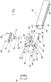
Figure 1 shows schematically, in an exploded view, the support bracket and the metal profile of a preferred embodiment of the present invention and its relative housing profile; -
Figure 2 shows schematically, in an exploded view, the same bracket assembled in its components, one of the carriages with the relative sliding rail, and the same housing profile and part of one of the leaves or doors with the seat for said profile; -
Figure 3 shows schematically, in a front view, the assembly formed by the leaf or door coupled to the sliding rail of the carriage connected to the bracket the preferred embodiment of the present invention; -
Figure 4 shows schematically, in partial longitudinal cross-section, the same bracket in the adjustment step which brings the door or leaf to rise; -
Figure 5 shows schematically, in partial longitudinal cross-section, the same bracket in the adjustment step which brings the door or leaf to lower itself; -
Figure 6 is a partial enlargement of the bracket according toFigure 5 . With initial reference tofigures 1 and2 , the support bracket, globally denoted by reference numeral 10 infigure 2 , comprises a body inmetal 12 such as zamak or other suitable material, of a substantially parallelepiped shape extending horizontally, with the lower face open, the upper side 12' having a planar extension and the front part preferably with a convex arched profile. The bracket 10 is designed to be positioned and stabilized in a metal profile of the known type, shown schematically asreference numeral 14; said profile defines a "U" section in which the free upper end of each of the opposite vertical branches is bent at 90° in the direction of the longitudinal axis and forms oppositelips 16 and 16' extending longitudinally. Said lips reduce the upper access space 14' to the cavity of theprofile 14, indicated as 14". The width of thebody 12 of the bracket 10 is greater than the upper space 14' of theprofile 14, so that said bracket is inserted into the aforementioned profile starting from one of its open heads and is then stabilised in it by the means described below. Theprofile 14 is previously housed in acavity 18 formed along the top edge 20 of the door or leaf, schematically shown asreference numeral 22 infigure 2 ; said cavity extends horizontally and reaches one of the vertical edges, indicated as 24 in the same figure, of the door orleaf 22. AlthoughFigures 1 and2 show a single bracket 10 in relation to theprofile 14, is to be understood that along the top edge 20 opposite andspecular cavities 18 are made for therespective profiles 14, each of which, fixed withscrews 26 in the respective profile, houses a bracket 10; this in function of the need to perfectly align the door orleaf 22 with the floor or bottom of the cabinet, acting at the two opposite ends as specified below. - The attachment of each bracket in the
recess 14" of theprofile 14 is preferably achieved by means of aslider 28, typically in synthetic material such as reinforced nylon, consisting of a prismatic body provided with superposed and aligned openings extended horizontally 30 and 32, the latter threaded; saidopenings body 12. At the bottom of theslider 28, opposite lugs with aninclined profile 34 project, designed to abut and slide along corresponding inclined portions 36 of thebody 12 of the bracket 10. In particular, the inclined portions 36 are made on saidbody 12 in the rear part thereof opposite the front part with the convex arched profile, at the bottom of the opposite sides. The rear wall of thebody 12 opposite the front wall defines a vertical extension and presents, in a position next to the upper side 12', a threaded throughhole 38 for afirst screw 40, provided with anannular grooving 42 at the front end; said screw has a larger diameter in the central-rear area along which the threading is provided. Below thehole 38 and in alignment therewith a through opening 44 for asecond screw 46 is made on said rear wall, having the function of stabilizing the bracket 10 in theprofile 14 by means of the movement of theslider 28, as described in greater detail below. The bracket 10 further comprises a pair of lower 48 andupper wedges 50, superposed along the respective inclined surfaces. From the inclined surface of thelower wedge 48 an opening or vertical throughhole 52 extends, in which a threadedpin 54 is inserted designed to engage with acarriage 56, in itself known, sliding in a conventional profile or guide rail 56'. Said latter typically presents a quadrangular cross-section and is centrally open along the underside for the passage of the threadedpin 54 which connects the bracket 10 to thecarriage 56. In theupper wedge 50, the exposed upper surface defines a planar extension, being designed to abut constantly with the lower face of the upper side 12' of thebody 12. Theupper wedge 50 is also provided with a vertical throughaperture 58 crossed by the threadedpin 54; in this case, such opening defines an ovoid shape extended in the longitudinal direction along the aforementioned wedge, starting from its flat upper face. Said wedge also comprises a vertically extendingwall 60, facing in the direction of theslider 28, at the top of which a groove is made in a central position, which forms arace 62 oriented vertically. Therace 62 constitutes the engagement seat of theannular grooving 42 of thefirst screw 40, provided with a thread in the rear part 40' of greater diameter. - The two superposed lower 48 and
upper wedges 50 crossed by the threadedpin 54 are inserted from below into thebody 12 and abut against theslider 28 in the part near the convex arched front face of said body. The upper side 12' of said latter is provided with athrough hole 64, which allows the threadedpin 54 to protrude from thebody 12 to be screwed to thecarriage 56. Said pin is provided, about halfway along its extension, with a notching 66 which houses a Seeger ring having the function of preventing the excessive tightening of the bracket 10, by means of a conventional nut, to thecarriage 56; this way, instead, the threadedpin 54 can perform a vertical excursion, albeit limited nevertheless sufficient to move the leaf ordoor 22 to adjust its height.Figures 4 and 5 illustrate these steps and also illustrate other advantageous features of the invention. In the first place, thehead 70 of the threadedpin 54 is shaped, preferably faceted, to fit precisely into acomplementary seat 72 made along the bottom surface of thelower wedge 48; such seat is visible inFigures 4 and 5 . This way it is possible to prevent the pin from freely rotating, with the risk of unscrewing itself from thecarriage 56 consequently lowering the door orleaf 22 previously levelled. - Secondly, the threaded
pin 54 is combined with atorsion spring 74 made of harmonic steel, typically in the form of a foil, positioned below thehead 70 of the threadedpin 54 and extending longitudinally in the lower part of thebody 12; said latter is closed by acover plate 76 made of metal or other suitable material, attached to the body withscrews 78 or equivalent. A further plastic cover orcap 80 closes the heads of theprofile 14, shielding the respective brackets 10 inserted and stabilized therein. - In the operating step, the bracket 10 assembled in its components is inserted in the
profile 14, already attached by thescrews 26 in thecavity 18 of the door orleaf 22; said bracket is placed in theaforementioned profile 14 substantially flush with themouth 14" and is stabilized therein by thesecond screw 46. Such latter, inserted in thecavity 18 of thebody 12 is engaged in the threadedhole 32 of theslider 28, provided with the oppositeinclined lugs 34. The sliding of such lugs on the corresponding inclined portions 36 of thebody 12 makes the latter rise and abut from below with the upper side 12' and thelips 16 and 16' of theprofile 14. The bracket is thus stabilized. This sliding is achieved as a result of thesecond screw 46 being screwed fully into the threadedhole 32 of theslider 28, protruding from the opposite side of the said slider and abutting with afixed part 82 of thebody 12, as visible inFigures 4 and 5 and, more in particular, inFigure 6 . At the moment in which thesecond screw 46 screwed into thehole 32 of theslider 28 abuts said fixedpart 82, the slider moves back and makes thebody 12 rise until it locks in theprofile 14, saidscrew 46 acting as a worm.. - Subsequently, the height adjustment of the door or
leaf 22 is realized by acting on thefirst screw 40, the threaded rear part 40' of which of greater diameter is engaged in the through opening 30 of theslider 28 and theannular grooving 42 of which is engaged in therace 62 of theupper wedge 50. As can be seen in particular fromFigures 4 and 5 , by loosening thescrew 40 theupper wedge 48 moves back with respect to thelower wedge 48, thetorsion spring 74 lifts and pushes the threadedpin 54 upwards, as shown infigure 4 . The bracket 10 which said pin protrudes from thus receives a corresponding upward thrust and being stabilized in theprofile 14 in turn fixed to the door orleaf 22, makes the latter rise to find the appropriate levelling. Conversely, as shown inFigure 5 , by tightening thescrew 40 theupper wedge 48 advances, thetorsion spring 74 is compressed and the threadedpin 54 is lowered, thus lowering the door orleaf 22. The presence on theupper wedge 50 of the through opening 58 of an ovoid shape allows the wedge to move with respect to saidlower wedge 48 without interfering with the threadedpin 54. Thetorsion spring 74 also keeps such threaded pin in constant tension which, being connected to thecarriage 56, prevents the door orleaf 22 from being subjected to impact and violent recoils in the vertical direction and to oscillations upon reaching the end stroke, also producing accentuated noise. - As may be seen from the above, the advantages which the invention achieves are evident.
- The use of the support bracket of the present invention makes it possible to substantially reduce the space between the sliding rail of the carriages and the hanging element; the sliding partition doors of rooms, in particular, can thus be easily arranged flush with the ceiling or recessed flush with the plasterboard false ceilings. The possibility of adjusting and laterally locking the door or leaf, which can thus be easily and quickly aligned with each other and/or with the floor is particularly advantageous.
- The presence of the torsion spring, in addition, contributes appreciably to preventing recoils in the vertical direction and possible oscillations of the door or leaf at the end stroke, at the same time reducing the noise.
- Despite the invention having been described above with particular reference to one of its embodiments, given solely by way of a non-limiting example, numerous modifications and variants will appear evident to a person skilled in the art in the light of the above description. The present invention therefore sets out to embrace all the modifications and variants which fall within the scope of the following claims.
Claims (4)
- A support bracket (10) with side locking and adjustment for sliding doors and leaves (22) and a metal profile (14), said support bracket (10) being positioned and stabilised in said metal profile (14) having a "U" section with the free upper end of each of the opposite vertical branches bent at 90° in the direction of the longitudinal axis to form opposite lips (16) and (16') extending longitudinally, attachable with screws (26) in a cavity (18) formed along the upper edge of said doors or leaves, wherein a threaded pin (54) of said support bracket (10) protruding from the top of said metal profile (14) is designed to engage with a carriage (56) sliding in a rail (56'), said support bracket (10) comprising a body (12) of a substantially parallelepiped shape extending in a horizontal direction with an upper side (12') and with an open lower face, characterized in that in the rear part of which opposite a mouth (14 ") of the profile (14) a slider (28) is placed, fitted at the bottom with opposite projecting and inclined lugs (34) designed to abut with corresponding inclined portions (36) made in the lower part of the opposite sides of said body (12) to move said slider, by means of a pair of superposed lower (48) and upper wedges (50), said slider (28) being provided with superposed through openings (30), (32), oriented in alignment with the longitudinal axis of the body (12), which respectively house a partially threaded first screw (40) provided with a thread in the central-rear part (40') defining the greatest diameter and presents, at the front end, an annular grooving (42) and a second screw (46) which stabilizes the bracket (10) in the profile (14) through the movement of said slider (28), to drive said upper side (12') to abut with said lips (16), (16'), and which is moved with respect to said slider (28) starting from a through opening (44) made at the bottom of the rear face of said body (12), said second screw (46) engaging in the threaded hole (32) formed by the other through opening (32) of said slider (28) from which it protrudes to abut with a fixed part (82) of said body (12), the thread made along the centre-rear part (40') of the first screw (40) engages in a threaded through hole (38) made on the rear face of the body (12), above the through opening (44), wherein said two lower (48) and upper wedges (50) are superposed along the respective inclined surfaces and are arranged in the body (12) in front of the slider (28), the lower wedge (48) being provided with a through opening or hole (52) which extends vertically starting from an inclined surface thereof, in said opening the threaded pin (54) being inserted, the head (70) of which is shaped and is recessed in a complementary seat (72) created on the lower face of said lower wedge (48) while the upper wedge (50) is provided with a vertical through opening (58) of an ovoid shape, extending longitudinally starting from its flat upper face, for the passage of the threaded pin (54), and the upper wedge (50) comprises a wall extending vertically, facing the slider (28), at the top of which a race (62) is centrally formed, in which the annular groove (42) of the first screw (40) engages.
- The bracket according to claim 1, characterised in that the threaded pin (54) is provided with a notching (66) for a Seeger ring, said pin protruding upwardly from the body (12) through a hole (64) made along the upper side (12').
- The bracket according to claim 1, characterised in that it comprises a torsion spring (74), placed below the threaded pin (54) and extending in a longitudinal direction in the body (12), said latter being provided below with a cover plate (76) attached with screws (78) or equivalent.
- The bracket according to one or more of the previous claims, characterised in that it comprises a shielding cap (80) to be applied to the mouth (14") of the profile (14) in which said bracket is inserted and stabilized.
Applications Claiming Priority (1)
| Application Number | Priority Date | Filing Date | Title |
|---|---|---|---|
| ITMI20140106 | 2014-01-28 |
Publications (2)
| Publication Number | Publication Date |
|---|---|
| EP2899351A1 EP2899351A1 (en) | 2015-07-29 |
| EP2899351B1 true EP2899351B1 (en) | 2018-01-31 |
Family
ID=50349732
Family Applications (1)
| Application Number | Title | Priority Date | Filing Date |
|---|---|---|---|
| EP14004424.9A Active EP2899351B1 (en) | 2014-01-28 | 2014-12-24 | Support bracket for sliding doors with side locking and adjustment and Metal profile |
Country Status (3)
| Country | Link |
|---|---|
| US (1) | US9376848B2 (en) |
| EP (1) | EP2899351B1 (en) |
| ES (2) | ES2664096T3 (en) |
Families Citing this family (16)
| Publication number | Priority date | Publication date | Assignee | Title |
|---|---|---|---|---|
| EP2851496A1 (en) * | 2013-09-18 | 2015-03-25 | Hawa Ag | Adjustable mounting device for a sliding element and sliding device |
| EP3182865B1 (en) * | 2014-08-19 | 2019-05-01 | Silent Gliss International Ag | Suspension unit for a curtain device and curtain device with such a suspension unit. |
| EP3020901B1 (en) * | 2014-11-14 | 2021-11-10 | dormakaba Deutschland GmbH | Roller carriage for mounting a sliding door with at least two mounting devices |
| EP3020900B1 (en) * | 2014-11-14 | 2018-09-05 | dormakaba Deutschland GmbH | Roller carriage for mounting a sliding door with height adjustment device |
| JP6587885B2 (en) * | 2015-09-30 | 2019-10-09 | アトムリビンテック株式会社 | Sliding door bounce suppression device |
| US10240843B2 (en) * | 2016-01-14 | 2019-03-26 | Viking Range, Llc | Refrigerator ice bin |
| DE102016202774A1 (en) * | 2016-02-23 | 2017-08-24 | Gebr. Willach Gmbh | sliding door system |
| TWM533704U (en) * | 2016-09-06 | 2016-12-11 | Syncmold Entpr Corp | Slide module |
| EP3822113A1 (en) * | 2016-11-15 | 2021-05-19 | Safran Seats USA LLC | Mini suite emergency egress solutions |
| KR102375560B1 (en) * | 2019-07-24 | 2022-03-17 | 정지숙 | Door roller for slide-door |
| USD936459S1 (en) * | 2019-10-14 | 2021-11-23 | Dirtt Environmental Solutions Ltd. | Door and ceiling frame component |
| USD974149S1 (en) * | 2019-10-16 | 2023-01-03 | Dirtt Environmental Solutions Ltd. | Ceiling hanger |
| CN111616727A (en) * | 2020-05-25 | 2020-09-04 | 赛诺威盛科技(北京)有限公司 | Adjusting mechanism, adjusting and assembling method and CT (computed tomography) equipment |
| CN112026798B (en) * | 2020-08-17 | 2024-07-02 | 中车长春轨道客车股份有限公司 | Adjustable side wall mount pad of railway passenger train equipment |
| CA3183789A1 (en) * | 2021-12-02 | 2023-06-02 | Amesbury Group, Inc. | Sliding door rollers |
| USD1005826S1 (en) * | 2022-01-06 | 2023-11-28 | Renin Canada Corp. | Sliding door bracket |
Family Cites Families (18)
| Publication number | Priority date | Publication date | Assignee | Title |
|---|---|---|---|---|
| US257401A (en) * | 1882-05-02 | Sheave for sliding doors | ||
| US477739A (en) * | 1892-06-28 | Door-hanger | ||
| US3283444A (en) * | 1964-12-11 | 1966-11-08 | Aluminite Mfg Co | Sliding door corner and roller assembly |
| US3442052A (en) * | 1967-05-02 | 1969-05-06 | American Aluminum Window Corp | Sealing bar for sliding glass door units |
| US3996643A (en) * | 1975-09-08 | 1976-12-14 | Steigerwald Joseph F | Roller wheel assembly for sliding closure |
| ZA8064B (en) * | 1979-01-24 | 1981-01-28 | Shaw Mfg Ltd | Load supporting roller assemblies |
| US4639970A (en) * | 1984-11-29 | 1987-02-03 | Alcan Aluminum Corporation | Roller assembly with stabilizer elements for sliding panels |
| IT221003Z2 (en) * | 1990-03-05 | 1993-12-21 | Fapim S.N.C. | TROLLEY FOR SUPPORTING SLIDING DOORS. |
| GR960100122A (en) * | 1996-04-11 | 1997-12-31 | System for the suspension of a sliding door with mechanism for adjusting its height and inclination. | |
| US5860189A (en) * | 1997-03-06 | 1999-01-19 | An; Tae-Heup | Door wheel |
| AUPO689097A0 (en) * | 1997-05-20 | 1997-06-12 | Anthony Bearings Pty Ltd | Improved door adjustment mechanism |
| TW435567U (en) * | 2000-09-07 | 2001-05-16 | Chen Chang Plastic Co Ltd | Improved structure for roller seat used in windows/ doors |
| US7712258B2 (en) * | 2004-04-22 | 2010-05-11 | K. Bradley Ewing | Suspension and sill system for sliding members |
| JP5069179B2 (en) | 2008-06-10 | 2012-11-07 | アトムリビンテック株式会社 | Runner equipment |
| ITMI20090574A1 (en) | 2009-04-09 | 2010-10-10 | Protek S R L | SUPPORT DEVICE PARTICULARLY FOR DOORS, SLIDING DOORS AND THE LIKE. |
| PL2246509T3 (en) * | 2009-04-28 | 2013-04-30 | Hawa Ag | Moving device for pivotable partition elements and furniture |
| CA2824683C (en) * | 2010-02-17 | 2018-09-25 | Ciilock Engineering Pty Ltd | Adjustable carriage |
| IT1400826B1 (en) | 2010-06-22 | 2013-07-02 | S C S P A | SYSTEM FOR ADJUSTING THE HEIGHT OF A SLIDING DOOR, IN PARTICULAR A SLIDING DOOR TO BE INSERTED IN A HIDDEN CABINET, MOUNTING KIT OF A SLIDING DOOR INSIDE A BOX, AND METHOD FOR INSERTING A DOOR INSIDE A BOX OF A COUNTERFRAME. |
-
2014
- 2014-12-24 EP EP14004424.9A patent/EP2899351B1/en active Active
- 2014-12-24 ES ES14004424.9T patent/ES2664096T3/en active Active
-
2015
- 2015-01-20 US US14/600,722 patent/US9376848B2/en active Active
- 2015-03-17 ES ES15718606T patent/ES2961841T3/en active Active
Non-Patent Citations (1)
| Title |
|---|
| None * |
Also Published As
| Publication number | Publication date |
|---|---|
| ES2664096T3 (en) | 2018-04-18 |
| ES2961841T3 (en) | 2024-03-14 |
| EP2899351A1 (en) | 2015-07-29 |
| US9376848B2 (en) | 2016-06-28 |
| US20150211275A1 (en) | 2015-07-30 |
Similar Documents
| Publication | Publication Date | Title |
|---|---|---|
| EP2899351B1 (en) | Support bracket for sliding doors with side locking and adjustment and Metal profile | |
| KR102024970B1 (en) | glass handrail for window | |
| US8413299B2 (en) | Hinge for door or window | |
| RU2724862C1 (en) | Device for sliding doors and wardrobe doors, equipped with several adjustments | |
| US20160369547A1 (en) | Sliding-Door Closer Set | |
| US20140259363A1 (en) | Removable header for a shower door track assembly | |
| US3183547A (en) | Hinge and closure assemblies for windows and the like | |
| IE20170097A1 (en) | Hinges | |
| WO2011115530A1 (en) | Method for mounting the frame of an interior door in a wall opening | |
| RU2435919C2 (en) | Door or window swivel hinge | |
| US20150096258A1 (en) | Door assembly | |
| EP2832276A1 (en) | Door assembly | |
| EP3162993B1 (en) | Locking mechanism for a window or door | |
| EP3039207B1 (en) | Leaf of a sliding window or sliding door and sliding window or sliding door provided with such a leaf | |
| KR102524922B1 (en) | Sliding door | |
| EP2789780B1 (en) | Support and adjustment device of a trolley for sliding doors or panels | |
| CA2848989A1 (en) | Shower door assembly with continuous control | |
| KR101600065B1 (en) | Slim-type frame frames for sliding doors | |
| KR101213506B1 (en) | Door clearance screening for furniture | |
| KR20180096122A (en) | Extruding panel and assembly type furniture | |
| KR101614451B1 (en) | Slim frame for sliding type door frame | |
| CN213234658U (en) | Pulley assembly adaptive to sliding door guide rail and shower room | |
| KR101226254B1 (en) | door stopper | |
| KR100663700B1 (en) | Lock apparatus for the furniture | |
| EP3328246B1 (en) | Anchoring group for wall cupboards with an increased capacity with regulation from above |
Legal Events
| Date | Code | Title | Description |
|---|---|---|---|
| PUAI | Public reference made under article 153(3) epc to a published international application that has entered the european phase |
Free format text: ORIGINAL CODE: 0009012 |
|
| 17P | Request for examination filed |
Effective date: 20141224 |
|
| AK | Designated contracting states |
Kind code of ref document: A1 Designated state(s): AL AT BE BG CH CY CZ DE DK EE ES FI FR GB GR HR HU IE IS IT LI LT LU LV MC MK MT NL NO PL PT RO RS SE SI SK SM TR |
|
| AX | Request for extension of the european patent |
Extension state: BA ME |
|
| 17P | Request for examination filed |
Effective date: 20151112 |
|
| RAP1 | Party data changed (applicant data changed or rights of an application transferred) |
Owner name: TERNO SCORREVOLI S.P.A. UNIPERSONALE |
|
| STAA | Information on the status of an ep patent application or granted ep patent |
Free format text: STATUS: EXAMINATION IS IN PROGRESS |
|
| 17Q | First examination report despatched |
Effective date: 20170308 |
|
| GRAP | Despatch of communication of intention to grant a patent |
Free format text: ORIGINAL CODE: EPIDOSNIGR1 |
|
| STAA | Information on the status of an ep patent application or granted ep patent |
Free format text: STATUS: GRANT OF PATENT IS INTENDED |
|
| INTG | Intention to grant announced |
Effective date: 20171006 |
|
| GRAS | Grant fee paid |
Free format text: ORIGINAL CODE: EPIDOSNIGR3 |
|
| GRAA | (expected) grant |
Free format text: ORIGINAL CODE: 0009210 |
|
| STAA | Information on the status of an ep patent application or granted ep patent |
Free format text: STATUS: THE PATENT HAS BEEN GRANTED |
|
| AK | Designated contracting states |
Kind code of ref document: B1 Designated state(s): AL AT BE BG CH CY CZ DE DK EE ES FI FR GB GR HR HU IE IS IT LI LT LU LV MC MK MT NL NO PL PT RO RS SE SI SK SM TR |
|
| REG | Reference to a national code |
Ref country code: GB Ref legal event code: FG4D Ref country code: CH Ref legal event code: EP |
|
| REG | Reference to a national code |
Ref country code: AT Ref legal event code: REF Ref document number: 967555 Country of ref document: AT Kind code of ref document: T Effective date: 20180215 |
|
| REG | Reference to a national code |
Ref country code: IE Ref legal event code: FG4D |
|
| REG | Reference to a national code |
Ref country code: DE Ref legal event code: R096 Ref document number: 602014020227 Country of ref document: DE |
|
| REG | Reference to a national code |
Ref country code: CH Ref legal event code: NV Representative=s name: BOVARD AG PATENT- UND MARKENANWAELTE, CH |
|
| REG | Reference to a national code |
Ref country code: ES Ref legal event code: FG2A Ref document number: 2664096 Country of ref document: ES Kind code of ref document: T3 Effective date: 20180418 |
|
| REG | Reference to a national code |
Ref country code: NL Ref legal event code: MP Effective date: 20180131 |
|
| REG | Reference to a national code |
Ref country code: LT Ref legal event code: MG4D |
|
| PG25 | Lapsed in a contracting state [announced via postgrant information from national office to epo] |
Ref country code: NO Free format text: LAPSE BECAUSE OF FAILURE TO SUBMIT A TRANSLATION OF THE DESCRIPTION OR TO PAY THE FEE WITHIN THE PRESCRIBED TIME-LIMIT Effective date: 20180430 Ref country code: NL Free format text: LAPSE BECAUSE OF FAILURE TO SUBMIT A TRANSLATION OF THE DESCRIPTION OR TO PAY THE FEE WITHIN THE PRESCRIBED TIME-LIMIT Effective date: 20180131 Ref country code: LT Free format text: LAPSE BECAUSE OF FAILURE TO SUBMIT A TRANSLATION OF THE DESCRIPTION OR TO PAY THE FEE WITHIN THE PRESCRIBED TIME-LIMIT Effective date: 20180131 Ref country code: HR Free format text: LAPSE BECAUSE OF FAILURE TO SUBMIT A TRANSLATION OF THE DESCRIPTION OR TO PAY THE FEE WITHIN THE PRESCRIBED TIME-LIMIT Effective date: 20180131 Ref country code: FI Free format text: LAPSE BECAUSE OF FAILURE TO SUBMIT A TRANSLATION OF THE DESCRIPTION OR TO PAY THE FEE WITHIN THE PRESCRIBED TIME-LIMIT Effective date: 20180131 |
|
| PG25 | Lapsed in a contracting state [announced via postgrant information from national office to epo] |
Ref country code: IS Free format text: LAPSE BECAUSE OF FAILURE TO SUBMIT A TRANSLATION OF THE DESCRIPTION OR TO PAY THE FEE WITHIN THE PRESCRIBED TIME-LIMIT Effective date: 20180531 Ref country code: BG Free format text: LAPSE BECAUSE OF FAILURE TO SUBMIT A TRANSLATION OF THE DESCRIPTION OR TO PAY THE FEE WITHIN THE PRESCRIBED TIME-LIMIT Effective date: 20180430 Ref country code: RS Free format text: LAPSE BECAUSE OF FAILURE TO SUBMIT A TRANSLATION OF THE DESCRIPTION OR TO PAY THE FEE WITHIN THE PRESCRIBED TIME-LIMIT Effective date: 20180131 Ref country code: PL Free format text: LAPSE BECAUSE OF FAILURE TO SUBMIT A TRANSLATION OF THE DESCRIPTION OR TO PAY THE FEE WITHIN THE PRESCRIBED TIME-LIMIT Effective date: 20180131 Ref country code: GR Free format text: LAPSE BECAUSE OF FAILURE TO SUBMIT A TRANSLATION OF THE DESCRIPTION OR TO PAY THE FEE WITHIN THE PRESCRIBED TIME-LIMIT Effective date: 20180501 Ref country code: LV Free format text: LAPSE BECAUSE OF FAILURE TO SUBMIT A TRANSLATION OF THE DESCRIPTION OR TO PAY THE FEE WITHIN THE PRESCRIBED TIME-LIMIT Effective date: 20180131 Ref country code: SE Free format text: LAPSE BECAUSE OF FAILURE TO SUBMIT A TRANSLATION OF THE DESCRIPTION OR TO PAY THE FEE WITHIN THE PRESCRIBED TIME-LIMIT Effective date: 20180131 |
|
| PG25 | Lapsed in a contracting state [announced via postgrant information from national office to epo] |
Ref country code: RO Free format text: LAPSE BECAUSE OF FAILURE TO SUBMIT A TRANSLATION OF THE DESCRIPTION OR TO PAY THE FEE WITHIN THE PRESCRIBED TIME-LIMIT Effective date: 20180131 Ref country code: AL Free format text: LAPSE BECAUSE OF FAILURE TO SUBMIT A TRANSLATION OF THE DESCRIPTION OR TO PAY THE FEE WITHIN THE PRESCRIBED TIME-LIMIT Effective date: 20180131 Ref country code: EE Free format text: LAPSE BECAUSE OF FAILURE TO SUBMIT A TRANSLATION OF THE DESCRIPTION OR TO PAY THE FEE WITHIN THE PRESCRIBED TIME-LIMIT Effective date: 20180131 |
|
| REG | Reference to a national code |
Ref country code: DE Ref legal event code: R097 Ref document number: 602014020227 Country of ref document: DE |
|
| PG25 | Lapsed in a contracting state [announced via postgrant information from national office to epo] |
Ref country code: DK Free format text: LAPSE BECAUSE OF FAILURE TO SUBMIT A TRANSLATION OF THE DESCRIPTION OR TO PAY THE FEE WITHIN THE PRESCRIBED TIME-LIMIT Effective date: 20180131 Ref country code: SM Free format text: LAPSE BECAUSE OF FAILURE TO SUBMIT A TRANSLATION OF THE DESCRIPTION OR TO PAY THE FEE WITHIN THE PRESCRIBED TIME-LIMIT Effective date: 20180131 Ref country code: SK Free format text: LAPSE BECAUSE OF FAILURE TO SUBMIT A TRANSLATION OF THE DESCRIPTION OR TO PAY THE FEE WITHIN THE PRESCRIBED TIME-LIMIT Effective date: 20180131 Ref country code: CZ Free format text: LAPSE BECAUSE OF FAILURE TO SUBMIT A TRANSLATION OF THE DESCRIPTION OR TO PAY THE FEE WITHIN THE PRESCRIBED TIME-LIMIT Effective date: 20180131 |
|
| PLBE | No opposition filed within time limit |
Free format text: ORIGINAL CODE: 0009261 |
|
| STAA | Information on the status of an ep patent application or granted ep patent |
Free format text: STATUS: NO OPPOSITION FILED WITHIN TIME LIMIT |
|
| 26N | No opposition filed |
Effective date: 20181102 |
|
| PG25 | Lapsed in a contracting state [announced via postgrant information from national office to epo] |
Ref country code: SI Free format text: LAPSE BECAUSE OF FAILURE TO SUBMIT A TRANSLATION OF THE DESCRIPTION OR TO PAY THE FEE WITHIN THE PRESCRIBED TIME-LIMIT Effective date: 20180131 |
|
| REG | Reference to a national code |
Ref country code: AT Ref legal event code: UEP Ref document number: 967555 Country of ref document: AT Kind code of ref document: T Effective date: 20180131 |
|
| GBPC | Gb: european patent ceased through non-payment of renewal fee |
Effective date: 20181224 |
|
| PG25 | Lapsed in a contracting state [announced via postgrant information from national office to epo] |
Ref country code: MC Free format text: LAPSE BECAUSE OF FAILURE TO SUBMIT A TRANSLATION OF THE DESCRIPTION OR TO PAY THE FEE WITHIN THE PRESCRIBED TIME-LIMIT Effective date: 20180131 Ref country code: LU Free format text: LAPSE BECAUSE OF NON-PAYMENT OF DUE FEES Effective date: 20181224 |
|
| REG | Reference to a national code |
Ref country code: IE Ref legal event code: MM4A |
|
| REG | Reference to a national code |
Ref country code: BE Ref legal event code: MM Effective date: 20181231 |
|
| PG25 | Lapsed in a contracting state [announced via postgrant information from national office to epo] |
Ref country code: IE Free format text: LAPSE BECAUSE OF NON-PAYMENT OF DUE FEES Effective date: 20181224 Ref country code: FR Free format text: LAPSE BECAUSE OF NON-PAYMENT OF DUE FEES Effective date: 20181231 |
|
| PG25 | Lapsed in a contracting state [announced via postgrant information from national office to epo] |
Ref country code: BE Free format text: LAPSE BECAUSE OF NON-PAYMENT OF DUE FEES Effective date: 20181231 |
|
| PG25 | Lapsed in a contracting state [announced via postgrant information from national office to epo] |
Ref country code: GB Free format text: LAPSE BECAUSE OF NON-PAYMENT OF DUE FEES Effective date: 20181224 |
|
| PG25 | Lapsed in a contracting state [announced via postgrant information from national office to epo] |
Ref country code: MT Free format text: LAPSE BECAUSE OF NON-PAYMENT OF DUE FEES Effective date: 20181224 |
|
| PG25 | Lapsed in a contracting state [announced via postgrant information from national office to epo] |
Ref country code: TR Free format text: LAPSE BECAUSE OF FAILURE TO SUBMIT A TRANSLATION OF THE DESCRIPTION OR TO PAY THE FEE WITHIN THE PRESCRIBED TIME-LIMIT Effective date: 20180131 |
|
| PG25 | Lapsed in a contracting state [announced via postgrant information from national office to epo] |
Ref country code: PT Free format text: LAPSE BECAUSE OF FAILURE TO SUBMIT A TRANSLATION OF THE DESCRIPTION OR TO PAY THE FEE WITHIN THE PRESCRIBED TIME-LIMIT Effective date: 20180131 |
|
| PG25 | Lapsed in a contracting state [announced via postgrant information from national office to epo] |
Ref country code: MK Free format text: LAPSE BECAUSE OF NON-PAYMENT OF DUE FEES Effective date: 20180131 Ref country code: CY Free format text: LAPSE BECAUSE OF FAILURE TO SUBMIT A TRANSLATION OF THE DESCRIPTION OR TO PAY THE FEE WITHIN THE PRESCRIBED TIME-LIMIT Effective date: 20180131 Ref country code: HU Free format text: LAPSE BECAUSE OF FAILURE TO SUBMIT A TRANSLATION OF THE DESCRIPTION OR TO PAY THE FEE WITHIN THE PRESCRIBED TIME-LIMIT; INVALID AB INITIO Effective date: 20141224 |
|
| P01 | Opt-out of the competence of the unified patent court (upc) registered |
Effective date: 20230601 |
|
| PGFP | Annual fee paid to national office [announced via postgrant information from national office to epo] |
Ref country code: IT Payment date: 20231229 Year of fee payment: 10 Ref country code: AT Payment date: 20231213 Year of fee payment: 10 |
|
| PGFP | Annual fee paid to national office [announced via postgrant information from national office to epo] |
Ref country code: ES Payment date: 20240117 Year of fee payment: 10 |
|
| PGFP | Annual fee paid to national office [announced via postgrant information from national office to epo] |
Ref country code: DE Payment date: 20240117 Year of fee payment: 10 Ref country code: CH Payment date: 20240120 Year of fee payment: 10 |