EP3328246B1 - Anchoring group for wall cupboards with an increased capacity with regulation from above - Google Patents
Anchoring group for wall cupboards with an increased capacity with regulation from above Download PDFInfo
- Publication number
- EP3328246B1 EP3328246B1 EP16745079.0A EP16745079A EP3328246B1 EP 3328246 B1 EP3328246 B1 EP 3328246B1 EP 16745079 A EP16745079 A EP 16745079A EP 3328246 B1 EP3328246 B1 EP 3328246B1
- Authority
- EP
- European Patent Office
- Prior art keywords
- wall
- slide
- cupboard
- respect
- regulation
- Prior art date
- Legal status (The legal status is an assumption and is not a legal conclusion. Google has not performed a legal analysis and makes no representation as to the accuracy of the status listed.)
- Active
Links
- 238000004873 anchoring Methods 0.000 title claims description 38
- 230000004913 activation Effects 0.000 claims description 14
- 230000000903 blocking effect Effects 0.000 claims description 4
- 230000000295 complement effect Effects 0.000 claims description 3
- 238000003780 insertion Methods 0.000 claims description 3
- 230000037431 insertion Effects 0.000 claims description 3
- 238000000605 extraction Methods 0.000 claims description 2
- 230000001105 regulatory effect Effects 0.000 description 4
- 230000000694 effects Effects 0.000 description 3
- 230000007246 mechanism Effects 0.000 description 3
- 230000001276 controlling effect Effects 0.000 description 2
- 238000007665 sagging Methods 0.000 description 2
- 239000002023 wood Substances 0.000 description 2
- 230000008878 coupling Effects 0.000 description 1
- 238000010168 coupling process Methods 0.000 description 1
- 238000005859 coupling reaction Methods 0.000 description 1
- 230000004048 modification Effects 0.000 description 1
- 238000012986 modification Methods 0.000 description 1
- 239000011120 plywood Substances 0.000 description 1
Images


Classifications
-
- A—HUMAN NECESSITIES
- A47—FURNITURE; DOMESTIC ARTICLES OR APPLIANCES; COFFEE MILLS; SPICE MILLS; SUCTION CLEANERS IN GENERAL
- A47B—TABLES; DESKS; OFFICE FURNITURE; CABINETS; DRAWERS; GENERAL DETAILS OF FURNITURE
- A47B95/00—Fittings for furniture
- A47B95/008—Suspension fittings for cabinets to be hung on walls
Definitions
- the present invention relates to an anchoring group for the wall assembly of wall cupboards with an increased capacity with regulation from above.
- anchoring group generally indicates the combination of a plate (support), that can be fixed to the wall by means of screws and/or dowels, and an anchoring device (so-called hanging bracket) comprising a hook that can be fixed to the furniture.
- wall cupboards are usually provided with a rear wall, called "lining", which typically consists of a plywood panel or made of thin wood.
- the lining can have a double function, both aesthetic for simply closing the back of the cupboard, and also structural for hanging the same cupboard by fixing the hanging bracket to said lining.
- the hanging bracket of the anchoring group must be mainly fixed to structural parts of the cupboard, such as for example, the side shoulders, which are always produced with a load-bearing function, having an adequate thickness and resistance for the purpose, sometimes supported by a fixing also to the upper top of the cupboard.
- the hanging bracket is fixed to the lining of the cupboard and the anchoring support is fixed to the wall of the environment or building.
- the hanging bracket does not have a valid and stable coupling in the thin layer of wood or the like forming the panel.
- This fixing with the insertion of screws or similar elements can also easily cause breakage if the panel is particularly thin and can therefore lead to a possible sagging of the wall cupboard when it is loaded.
- the anchoring groups used must be able to be regulated, in the sense that the hanging bracket, or rather its parts, must be movable with respect to the supporting point to allow a regulation in height (vertical) and also in depth (horizontal).
- the anchoring groups must not have complex mechanisms or be difficult to implement, in any case avoiding difficulty in their regulation in height and depth.
- a further problem connected with the positioning of these wall cupboards lies in the need for holes in the lining and/or panels, allowing the passage of a tool that effects horizontal and vertical adjustments.
- Holing in the lining and/or panels in visible positions is not desirable, as the wall cupboard, for example, has a certain value and must not be ruined by making holes that can easily be seen by an observer, even if covered by specific caps.
- the wall cupboard for example, has a certain value and must not be ruined by making holes that can easily be seen by an observer, even if covered by specific caps.
- the holes and/or relative caps formed in the lining are visible.
- the objective of the present invention is therefore to overcome the drawbacks previously indicated.
- the present invention is proposed as an alternative to the known anchoring groups and already present on the market, in particular when the panels of the cupboard are thin.
- an anchoring group has been conceived for the wall assembly of wall cupboards with an increased capacity with regulation from above, having the characteristics specified in the enclosed claims.
- this shows as a whole with the reference number 11, an embodiment example of an anchoring group according to the invention comprising a pair of hidden hanging-bracket devices adjustable from above, for the wall assembly of a wall cupboard.
- said anchoring group 11 comprises a pair of hanging-bracket devices 12, of the adjustable type and suitable for being assembled on a wall or panel 23 by means of fixing dowels 24.
- a pair of supporting plates 22 are provided at the rear of a wall cupboard P, in a hidden position, in contact with a lining 13, constrained laterally to a shoulder 14 and above a top 15 of the wall cupboard P. It is immediately evident that the hanging bracket or its mechanisms can be produced in various alternative embodiments.
- each hanging bracket device 12 comprises an anchoring base or plate element 16 and a hooking element 17.
- the plate element 16 is provided with at least a pair of holes 60 suitable for receiving the fixing dowels 24, produced in opposite parts of the plate element 16 itself, for constraining it to the wall 23.
- Each hooking element 17 of each hanging bracket 12 is coupled in the front with the same plate element 16 to receive and constrain each supporting plate 22 which is fixed at the rear of the wall cupboard P.
- said fixing is effected thanks to the presence, in each supporting plate 22, of holes 61 formed on side edges 62 and upper edges (if present) of each plate 22 which are juxtaposed with respect to the shoulder 14 and top 15 and constrained by means of screws for obtaining its stable positioning.
- Each hanging bracket 12 comprises a slide 25, sliding linearly with respect to the plate element or flange 16 in a first direction F, whereas the hooking element 17 is at least partly associated with the slide 25.
- the hooking element 17 is in fact movable with respect to the slide 25 in at least a second direction F1, substantially perpendicular with respect to the first direction.
- Each plate element or flange 16 also comprises at least two sliding rails 26 which cooperate with the relative slide 25.
- the slide 25 provides sliding guides 27 destined for cooperating with the respective rails 26 for guiding the sliding of the slide 25 in the first direction, preferably in a vertical direction in an assembled condition.
- the anchoring group comprises regulation means for controlling the sliding of the slide 25 with respect to the plate element or flange 16.
- Said means preferably comprise: a threaded seat 28 formed in the slide 25, an abutment flap 29, having a pair of holes and integral with the plate element 16 and which extends perpendicularly to the rails 26, and a regulation screw 30, accessible and operable from above, cooperating with the abutment flap 29 and with the threaded seat 28.
- This cooperation is such as to allow the sliding of the slide 25 in the above-mentioned first direction F.
- the regulation screw 30 is kept firmly in position with respect to the abutment flap 29, but rotates, thanks to the provision of a blocking ring 31 such as a Seeger ring, which is housed in an annular seat 31A formed below its head 30A which is therefore firmly constrained to the flap 29, but free to rotate.
- each hanging-bracket device 12 comprises activation means for controlling the movement of the hooking element 17 in the second direction F1.
- said activation means comprise a drive screw 32, accessible and operable from above, at least partly housed in the slide 25 and positioned parallelly to the regulation screw 30.
- Said drive screw 32 is also kept firmly in position with respect to the abutment flap 29, but rotates, thanks to the provision of a blocking ring 33, such as a Seeger ring, which is housed in an annular seat 33A formed below its head 32A which is thus firmly constrained to the flap 29, but free to rotate.
- said activation means in addition to comprising in this example the drive screw 32, having a polygonal stem 34, for example hexagonal, provide a cylindrical element 35, provided externally with a portion in the form of a worm-screw 36, and housed in the slide 25, kept rotatingly in position by a pin 37.
- the cylindrical element 35 is internally and axially provided with a cavity 38, having a polygonal form complementary to that of the stem 34 of the drive screw 32.
- Said cavity 38 is also provided in both the head of the regulation screw 30 and in the head of the drive screw 32 for receiving, as described hereunder, the tip of a screwdriver or rotation key.
- the pin 37 is inserted, in an assembled condition, in the slide 25 and then also in the throat 39 of the cylindrical element 35.
- the portion in the form of a worm screw 36 of the cylindrical element 35 cooperates with a toothed wheel 40, also housed in the slide 25 and rotatingly withheld with respect to the same.
- the hooking element 17 is provided with a partially threaded body 41 cooperating with a threaded seat 42 inside the toothed wheel 40.
- the body 41 has two smooth opposite planes (or flat portions) (41A) that slide inside complementary guiding seats of a hole of the slide 25.
- the body 41 of the hooking element 17 can be moved horizontally, in an extraction/insertion direction according to the arrow F1, from the toothed wheel 40 following the rotation of the latter, when activated by the portion in the form of a worm screw 36 of the cylindrical element 35.
- the axes of the portion in the form of a worm screw 36 of the cylindrical element 35, of the drive screw 32 and screw 30 are parallel to each other, so that access by means of keys or screwdrivers for effecting regulations of the wall cupboard P can be obtained by acting from the same part, i.e. directly from above.
- the constraint of the hanging brackets 12 to the wall 23 allows a safe and stable positioning of the anchoring group, avoiding any possible breakage of the wooden parts or breakage points.
- the horizontal or vertical movement of the wall cupboard P can be advantageously regulated, acting on only one side, i.e. from above, and by simply acting with a screwdriver 45.
- FIGs 2, 2A and 3, 3A show how accessibility to the hanging bracket 12 is achieved through the screwdriver 45 introduced from above alternatively in either of the two holes 43 of the top 15 of the wall cupboard P.
- each hanging bracket 12 is constrained to the wall 23 thus creating an increased capacity which prevents any possible sagging also in the case of a considerable load. Furthermore, each supporting plate 22 collaborating with the respective hooking element 17 of the hanging bracket 12 is firmly positioned on the rear part of the cupboard without any holing, for example in correspondence with the convergence between the top 15 and the shoulder 14, in a particularly resistant point of the structure of the wall cupboard P.
- Figure 5 shows by way of example how the screwdriver 45 is introduced from above into one of the holes 43 of the top 15 to effect the adjustment in a horizontal direction, i.e. in depth, according to the arrow F1, after juxtaposing the wall cupboard P with relative supporting plates 22 and the respective hooking element 17 of the corresponding hanging brackets 12, as indicated by the arrow K in the section of figure 4 .
- figure 6 shows how the wall cupboard P has been perfectly regulated in position by moving it as required towards the wall 23.
- an anchoring group has been provided in which the hanging bracket is fixed to the wall or panel with respect to which the wall cupboard P, bearing anchoring supports such as plates or a single bar, must be positioned, optimizing the stable and safe positioning of the wall cupboard also in the presence of particularly thin panels of the top, shoulder and base.
- each anchoring group comprises regulation means and activation means of the reciprocal position between the hanging-bracket device 12, the hooking element 17 and the anchoring support 22 to effect a regulation in the position of the wall cupboard P with respect to the wall 23.
- Said regulation is effected in two directions F, F1, perpendicular to each other, vertically (in height) and in horizontally (in depth) respectively and the regulation and activation are advantageously effected from above.
Description
- The present invention relates to an anchoring group for the wall assembly of wall cupboards with an increased capacity with regulation from above.
- At present, the definition "anchoring group" generally indicates the combination of a plate (support), that can be fixed to the wall by means of screws and/or dowels, and an anchoring device (so-called hanging bracket) comprising a hook that can be fixed to the furniture.
- Furthermore, for a better understanding of the problems associated with anchoring groups and their application, it should also be pointed out that wall cupboards are usually provided with a rear wall, called "lining", which typically consists of a plywood panel or made of thin wood.
- The lining can have a double function, both aesthetic for simply closing the back of the cupboard, and also structural for hanging the same cupboard by fixing the hanging bracket to said lining.
- In any case, the hanging bracket of the anchoring group must be mainly fixed to structural parts of the cupboard, such as for example, the side shoulders, which are always produced with a load-bearing function, having an adequate thickness and resistance for the purpose, sometimes supported by a fixing also to the upper top of the cupboard.
- An example of this application is known from international patent application
WO 2012/140467 of the holder. - In this document, the hanging bracket is fixed to the lining of the cupboard and the anchoring support is fixed to the wall of the environment or building.
- This type of application, however, is not suitable when the wall cupboard does not have a particularly sturdy structure.
- The use of particularly thin structural panels, in fact, hinders the firm positioning of the hanging bracket to the cupboard.
- Thin panels of both the shoulder and top do not support the firm positioning of the hanging bracket and above all are not suitable for validly "bearing" the cupboard and its contents once the hanging bracket has been fixed to them.
- The hanging bracket does not have a valid and stable coupling in the thin layer of wood or the like forming the panel.
- This fixing with the insertion of screws or similar elements can also easily cause breakage if the panel is particularly thin and can therefore lead to a possible sagging of the wall cupboard when it is loaded.
- In this situation of thin panelling, moreover, the anchoring groups used must be able to be regulated, in the sense that the hanging bracket, or rather its parts, must be movable with respect to the supporting point to allow a regulation in height (vertical) and also in depth (horizontal).
- Only in this way is it possible to position the cupboard correctly on the wall, also with respect to other adjacent furniture.
- Furthermore, also in this situation of a thin structure of the cupboard, the anchoring groups must not have complex mechanisms or be difficult to implement, in any case avoiding difficulty in their regulation in height and depth.
- A further problem connected with the positioning of these wall cupboards lies in the need for holes in the lining and/or panels, allowing the passage of a tool that effects horizontal and vertical adjustments.
- Holing in the lining and/or panels in visible positions is not desirable, as the wall cupboard, for example, has a certain value and must not be ruined by making holes that can easily be seen by an observer, even if covered by specific caps. In particular, in the case of furniture that does not have closing doors, or with partially transparent doors, in which the holes and/or relative caps formed in the lining, are visible.
- The objective of the present invention is therefore to overcome the drawbacks previously indicated.
- Furthermore, the present invention is proposed as an alternative to the known anchoring groups and already present on the market, in particular when the panels of the cupboard are thin.
- In view of the above objectives, according to the present invention, an anchoring group has been conceived for the wall assembly of wall cupboards with an increased capacity with regulation from above, having the characteristics specified in the enclosed claims.
- The structural and functional characteristics of the present invention and its advantages with respect to the known art will appear even more evident from the following description, referring to the enclosed drawings, which show embodiment examples of an anchoring group produced according to the present invention.
- In the drawings:
-
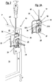
figure 1 shows a perspective view of an adjustable anchoring group for the wall assembly of a wall cupboard with regulation from above in a non-limiting embodiment according to the present invention, in which the wall cupboard has a pair of anchoring plates or bars and a pair of hanging brackets are shown in an exploded view from the cupboard, separate from each other and to be fixed to the wall, individually spaced; -
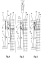
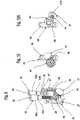
figures 2, 2A and3, 3A show perspective views of the single anchoring group in an assembled and operational position in an adjustment phase in height (vertical) and in an adjustment phase in depth (horizontal), respectively, and also partial views of the hanging bracket alone; -
figures 4, 5 and 6 show raised sectional side views of the anchoring group before its operational assembly, before the adjustment phase in depth (horizontal) and after the adjustment phase which shows the final position acquired by the cupboard with respect to a wall; -
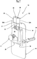
figure 7 shows an enlarged perspective view of a hanging bracket already shown infigure 1 ; -
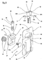
figure 8 is an exploded enlarged perspective view illustrating the hanging bracket forming part of the anchoring group according to the present invention shown infigure 1 ; -
figure 9 is a perspective view of the mechanism of the hanging bracket offigure 8 , assembled, partially split and sectioned; -
figures 10 and 10A show two differently oriented perspective views of details of activation means comprising a screw produced in the form of a worm screw and a toothed wheel that cooperates with said screw for regulating the hooking element. - With particular reference to
figure 1 , this shows as a whole with thereference number 11, an embodiment example of an anchoring group according to the invention comprising a pair of hidden hanging-bracket devices adjustable from above, for the wall assembly of a wall cupboard. - According to the invention, said
anchoring group 11 comprises a pair of hanging-bracket devices 12, of the adjustable type and suitable for being assembled on a wall orpanel 23 by means offixing dowels 24. A pair of supportingplates 22 are provided at the rear of a wall cupboard P, in a hidden position, in contact with alining 13, constrained laterally to ashoulder 14 and above atop 15 of the wall cupboard P. It is immediately evident that the hanging bracket or its mechanisms can be produced in various alternative embodiments. - In the non-limiting embodiment shown, each
hanging bracket device 12 comprises an anchoring base orplate element 16 and ahooking element 17. Theplate element 16 is provided with at least a pair ofholes 60 suitable for receiving thefixing dowels 24, produced in opposite parts of theplate element 16 itself, for constraining it to thewall 23. - Each hooking
element 17 of eachhanging bracket 12 is coupled in the front with thesame plate element 16 to receive and constrain each supportingplate 22 which is fixed at the rear of the wall cupboard P. In particular, said fixing is effected thanks to the presence, in each supportingplate 22, ofholes 61 formed onside edges 62 and upper edges (if present) of eachplate 22 which are juxtaposed with respect to theshoulder 14 andtop 15 and constrained by means of screws for obtaining its stable positioning. - Each
hanging bracket 12 comprises aslide 25, sliding linearly with respect to the plate element orflange 16 in a first direction F, whereas thehooking element 17 is at least partly associated with theslide 25. The hookingelement 17 is in fact movable with respect to theslide 25 in at least a second direction F1, substantially perpendicular with respect to the first direction. - In this way, an adjustment of the wall cupboard P is obtained in two directions F, F1 perpendicular to each other, specifically vertically (in height) and horizontally (in depth).
- Each plate element or
flange 16 also comprises at least two slidingrails 26 which cooperate with therelative slide 25. Theslide 25 providessliding guides 27 destined for cooperating with therespective rails 26 for guiding the sliding of theslide 25 in the first direction, preferably in a vertical direction in an assembled condition. - Furthermore, the anchoring group comprises regulation means for controlling the sliding of the
slide 25 with respect to the plate element orflange 16. - Said means preferably comprise: a threaded
seat 28 formed in theslide 25, anabutment flap 29, having a pair of holes and integral with theplate element 16 and which extends perpendicularly to therails 26, and aregulation screw 30, accessible and operable from above, cooperating with theabutment flap 29 and with the threadedseat 28. This cooperation is such as to allow the sliding of theslide 25 in the above-mentioned first direction F. Theregulation screw 30 is kept firmly in position with respect to theabutment flap 29, but rotates, thanks to the provision of a blockingring 31 such as a Seeger ring, which is housed in anannular seat 31A formed below itshead 30A which is therefore firmly constrained to theflap 29, but free to rotate. - Furthermore, each hanging-
bracket device 12 comprises activation means for controlling the movement of the hookingelement 17 in the second direction F1. In particular, in the example shown, said activation means comprise adrive screw 32, accessible and operable from above, at least partly housed in theslide 25 and positioned parallelly to theregulation screw 30. Saiddrive screw 32 is also kept firmly in position with respect to theabutment flap 29, but rotates, thanks to the provision of a blockingring 33, such as a Seeger ring, which is housed in anannular seat 33A formed below itshead 32A which is thus firmly constrained to theflap 29, but free to rotate. - More specifically, said activation means, in addition to comprising in this example the
drive screw 32, having apolygonal stem 34, for example hexagonal, provide acylindrical element 35, provided externally with a portion in the form of a worm-screw 36, and housed in theslide 25, kept rotatingly in position by apin 37. - The
cylindrical element 35 is internally and axially provided with acavity 38, having a polygonal form complementary to that of thestem 34 of thedrive screw 32. Saidcavity 38 is also provided in both the head of theregulation screw 30 and in the head of thedrive screw 32 for receiving, as described hereunder, the tip of a screwdriver or rotation key. - The
pin 37 is inserted, in an assembled condition, in theslide 25 and then also in thethroat 39 of thecylindrical element 35. - The portion in the form of a
worm screw 36 of thecylindrical element 35 cooperates with atoothed wheel 40, also housed in theslide 25 and rotatingly withheld with respect to the same. - The hooking
element 17 is provided with a partially threadedbody 41 cooperating with a threadedseat 42 inside thetoothed wheel 40. - The
body 41 has two smooth opposite planes (or flat portions) (41A) that slide inside complementary guiding seats of a hole of theslide 25. - In this way, the
body 41 of the hookingelement 17 can be moved horizontally, in an extraction/insertion direction according to the arrow F1, from thetoothed wheel 40 following the rotation of the latter, when activated by the portion in the form of aworm screw 36 of thecylindrical element 35. - As can be seen in the figures, the axes of the portion in the form of a
worm screw 36 of thecylindrical element 35, of thedrive screw 32 andscrew 30 are parallel to each other, so that access by means of keys or screwdrivers for effecting regulations of the wall cupboard P can be obtained by acting from the same part, i.e. directly from above. - The possibility of effecting regulations from above, for example by means of pass-through holes or
recesses 43 formed in thetop 15 of the wall cupboard P, has the result of improving access to the regulations and allowing simplified assembly and adjustments. This eliminates the need for forming and having front pass-through holes on the lining, which are aesthetically unsightly. The positioning of holes orrecesses 43 in thetop 15 of the wall cupboard P eliminates any aesthetical problem, completely hiding them from the view of an observer. - Furthermore, the constraint of the
hanging brackets 12 to thewall 23 allows a safe and stable positioning of the anchoring group, avoiding any possible breakage of the wooden parts or breakage points. - In this way, the horizontal or vertical movement of the wall cupboard P can be advantageously regulated, acting on only one side, i.e. from above, and by simply acting with a
screwdriver 45. -
Figures 2, 2A and3, 3A show how accessibility to thehanging bracket 12 is achieved through thescrewdriver 45 introduced from above alternatively in either of the twoholes 43 of thetop 15 of the wall cupboard P. - More specifically, it can be seen how each hanging
bracket 12 is constrained to thewall 23 thus creating an increased capacity which prevents any possible sagging also in the case of a considerable load. Furthermore, each supportingplate 22 collaborating with the respective hookingelement 17 of the hangingbracket 12 is firmly positioned on the rear part of the cupboard without any holing, for example in correspondence with the convergence between thetop 15 and theshoulder 14, in a particularly resistant point of the structure of the wall cupboard P. -
Figure 5 shows by way of example how thescrewdriver 45 is introduced from above into one of theholes 43 of thetop 15 to effect the adjustment in a horizontal direction, i.e. in depth, according to the arrow F1, after juxtaposing the wall cupboard P with relative supportingplates 22 and therespective hooking element 17 of thecorresponding hanging brackets 12, as indicated by the arrow K in the section offigure 4 . - Once the adjustment has been effected, as indicated in
figure 5, figure 6 shows how the wall cupboard P has been perfectly regulated in position by moving it as required towards thewall 23. - According to the invention, an anchoring group has been provided in which the hanging bracket is fixed to the wall or panel with respect to which the wall cupboard P, bearing anchoring supports such as plates or a single bar, must be positioned, optimizing the stable and safe positioning of the wall cupboard also in the presence of particularly thin panels of the top, shoulder and base.
- It is therefore reiterated that each anchoring group comprises regulation means and activation means of the reciprocal position between the hanging-
bracket device 12, the hookingelement 17 and the anchoringsupport 22 to effect a regulation in the position of the wall cupboard P with respect to thewall 23. Said regulation is effected in two directions F, F1, perpendicular to each other, vertically (in height) and in horizontally (in depth) respectively and the regulation and activation are advantageously effected from above. - The implementation of the adjustments in depth and in height are therefore very practically effected directly from above with a screwdriver.
- Finally, all problems relating to the presence of visible holes in the elements of the wall cupboard and/or closing caps of the same holes, have been eliminated.
- In this way, the problems revealed in the prior art have been solved.
- Further variants, or equivalent modifications are also possible, all to be considered as being included in the scope as defined by the appended claims.
Claims (9)
- An adjustable anchoring group for the wall assembly (23) of wall-cupboards (P) comprising a hanging-bracket device (12), provided with an anchoring base (16) to a panel or wall (23) and a hooking element (17), and an anchoring support (22) to a wall-cupboard (P), regulation means and activation means of the reciprocal position being provided between said hanging-bracket device (12), said hooking element (17) and said anchoring support (22) in order to regulate the position of the wall-cupboard (P) with respect to the wall (23) according to two directions (F, F1) perpendicular to each other, vertically (in height) and horizontally (in depth), respectively, wherein both said regulation means and said activation means are accessible from above by means of holes (43) formed in a top (15) of the wall-cupboard (P), wherein said hanging-bracket (12) comprises a slide (25) sliding linearly with respect to said anchoring base (16) in a first direction, said hooking element (17) being at least partially associated with said slide (25) and movable with respect to the latter in at least a second direction substantially perpendicular with respect to said first direction, wherein said regulation means and said activation means are respectively associated with said slide (25) and said hooking element (17), and
said regulation means comprise: a threaded seat (28) formed in said slide (25), an abutment flap (29) integral with said base (16) which extends perpendicularly to the movement direction of said slide, and a regulation screw (30) cooperating with said abutment flap (29) and with said threaded seat (28) for allowing the sliding of said slide (25) in said first direction,
characterized in that said regulation screw (30) is kept firmly in position with respect to the abutment flap (29), but rotates, thanks to the provision of a blocking ring (31) which is housed in an annular seat (31A) situated below a head (30A) of said regulation screw (30) and above the abutment flap (29). - The group according to claim 1, characterized in that said base (16) comprises fixing holes (60), for receiving fixing dowels to said wall (23), and sliding rails (26) of said slide (25), and wherein said slide (25) comprises sliding guides (27), said rails (26) and said guides (27) being suitable for cooperating with each other for guiding the sliding of said slide (25) in at least a first direction.
- The group according to claim 1 or 2, characterized in that said regulation means accessible from above are suitable for controlling the sliding of said slide (25) with respect to said base (16).
- The group according to one or more of the previous claims from 1 to 3, characterized in that said activation means accessible from above are suitable for controlling said movement of said hooking element (17) in said second direction.
- An adjustable anchoring group for the wall assembly (23) of wall-cupboards (P) comprising a hanging-bracket device (12), provided with an anchoring base (16) to a panel or wall (23) and a hooking element (17), and an anchoring support (22) to a wall-cupboard (P), regulation means and activation means of the reciprocal position being provided between said hanging-bracket device (12), said hooking element (17) and said anchoring support (22) in order to regulate the position of the wall-cupboard (P) with respect to the wall (23) according to two directions (F, F1) perpendicular to each other, vertically (in height) and horizontally (in depth), respectively, wherein both said regulation means and said activation means are accessible from above by means of holes (43) formed in a top (15) of the wall-cupboard (P), wherein said hanging-bracket (12) comprises a slide (25) sliding linearly with respect to said anchoring base (16) in a first direction, said hooking element (17) being at least partially associated with said slide (25) and movable with respect to the latter in at least a second direction substantially perpendicular with respect to said first direction, wherein said regulation means and said activation means are respectively associated with said slide (25) and said hooking element (17), and said activation means comprise a drive screw (32) at least partially housed in said slide (25), said drive screw (32) being arranged parallelly to a regulation screw (30), characterized in that said drive screw (32) is kept firmly in position with respect to an abutment flap (29) of said base (16), but rotates, thanks to the provision of a blocking ring (33) which is housed in an annular seat (33A) situated below a head (32A) of said drive screw (32) and above the abutment flap (29).
- The group according to claim 5, characterized in that said drive screw (32) is provided with a polygonal stem (34) which extends in engagement inside a cylindrical element (35) which, in turn, is externally provided with a portion in the form of a worm-screw (36) which is engaged with a toothed wheel (40), said cylindrical element (35) and said toothed wheel (40) being housed in the slide (25) free to rotate, said hooking element (17) being provided with a partially threaded body (41) cooperating with a threaded seat (42) inside the toothed wheel (40) so as to move in said second direction.
- The group according to claim 6, characterized in that said threaded body (41) has two smooth opposite planes (or flat portions) (41A) that slide inside complementary guiding seats of a hole of the slide (25) so that said hooking element (17) can be moved horizontally, in an extraction/insertion direction from the toothed wheel (40) following the rotation of the latter.
- The group according to one or more of the previous claims, characterized in that said anchoring support positioned behind said wall-cupboard (P) is a single bar.
- The group according to one or more of claims 1 to 8, characterized in that said anchoring support positioned behind said wall-cupboard (P) consists of a pair of supporting plates (22).
Priority Applications (1)
| Application Number | Priority Date | Filing Date | Title |
|---|---|---|---|
| PL16745079T PL3328246T3 (en) | 2015-07-29 | 2016-07-20 | Anchoring group for wall cupboards with an increased capacity with regulation from above |
Applications Claiming Priority (2)
| Application Number | Priority Date | Filing Date | Title |
|---|---|---|---|
| ITUB2015A002604A ITUB20152604A1 (en) | 2015-07-29 | 2015-07-29 | ANCHORAGE GROUP FOR WALL MOUNTED FURNITURE WITH ADJUSTMENT FROM THE TOP |
| PCT/EP2016/067303 WO2017016955A1 (en) | 2015-07-29 | 2016-07-20 | Anchoring group for wall cupboards with an increased capacity with regulation from above |
Publications (2)
| Publication Number | Publication Date |
|---|---|
| EP3328246A1 EP3328246A1 (en) | 2018-06-06 |
| EP3328246B1 true EP3328246B1 (en) | 2019-09-25 |
Family
ID=54329964
Family Applications (1)
| Application Number | Title | Priority Date | Filing Date |
|---|---|---|---|
| EP16745079.0A Active EP3328246B1 (en) | 2015-07-29 | 2016-07-20 | Anchoring group for wall cupboards with an increased capacity with regulation from above |
Country Status (5)
| Country | Link |
|---|---|
| EP (1) | EP3328246B1 (en) |
| ES (1) | ES2760975T3 (en) |
| IT (1) | ITUB20152604A1 (en) |
| PL (1) | PL3328246T3 (en) |
| WO (1) | WO2017016955A1 (en) |
Family Cites Families (1)
| Publication number | Priority date | Publication date | Assignee | Title |
|---|---|---|---|---|
| ITMI20110591A1 (en) * | 2011-04-11 | 2012-10-12 | Leonardo Srl | ANCHOR GROUP FOR HANGING FURNITURE WITH UPPER ADJUSTMENT |
-
2015
- 2015-07-29 IT ITUB2015A002604A patent/ITUB20152604A1/en unknown
-
2016
- 2016-07-20 EP EP16745079.0A patent/EP3328246B1/en active Active
- 2016-07-20 WO PCT/EP2016/067303 patent/WO2017016955A1/en unknown
- 2016-07-20 ES ES16745079T patent/ES2760975T3/en active Active
- 2016-07-20 PL PL16745079T patent/PL3328246T3/en unknown
Non-Patent Citations (1)
| Title |
|---|
| None * |
Also Published As
| Publication number | Publication date |
|---|---|
| WO2017016955A1 (en) | 2017-02-02 |
| PL3328246T3 (en) | 2020-03-31 |
| ITUB20152604A1 (en) | 2017-01-29 |
| ES2760975T3 (en) | 2020-05-18 |
| EP3328246A1 (en) | 2018-06-06 |
Similar Documents
| Publication | Publication Date | Title |
|---|---|---|
| US9101211B2 (en) | Leveling system | |
| KR101558129B1 (en) | Door frame for sliding doors | |
| EP3025619B1 (en) | Anchoring group for wall cupboards with regulation from above | |
| JP2013518622A (en) | Drawer structure | |
| EP3248505B1 (en) | Anchoring device for panels | |
| EP3349618B1 (en) | Anchoring group for wall cupboards with facilitated assembly | |
| EP3328246B1 (en) | Anchoring group for wall cupboards with an increased capacity with regulation from above | |
| EP2510836B1 (en) | Supporting structure for supporting shelves on a wall | |
| EP2510834B1 (en) | Hidden device for the wall assembly of a structural component of a piece of furniture, with side regulation | |
| EP3328244B1 (en) | Anchoring group for wall cupboards with regulation from below | |
| EP3328245B1 (en) | Anchoring group for wall cupboards with an increased capacity with regulation from below | |
| EP3823498B1 (en) | Supporting device for a cantilevered tubular structure | |
| JP2009191562A (en) | Article storage utensil |
Legal Events
| Date | Code | Title | Description |
|---|---|---|---|
| STAA | Information on the status of an ep patent application or granted ep patent |
Free format text: STATUS: THE INTERNATIONAL PUBLICATION HAS BEEN MADE |
|
| PUAI | Public reference made under article 153(3) epc to a published international application that has entered the european phase |
Free format text: ORIGINAL CODE: 0009012 |
|
| STAA | Information on the status of an ep patent application or granted ep patent |
Free format text: STATUS: REQUEST FOR EXAMINATION WAS MADE |
|
| 17P | Request for examination filed |
Effective date: 20171116 |
|
| AK | Designated contracting states |
Kind code of ref document: A1 Designated state(s): AL AT BE BG CH CY CZ DE DK EE ES FI FR GB GR HR HU IE IS IT LI LT LU LV MC MK MT NL NO PL PT RO RS SE SI SK SM TR |
|
| AX | Request for extension of the european patent |
Extension state: BA ME |
|
| DAV | Request for validation of the european patent (deleted) | ||
| DAX | Request for extension of the european patent (deleted) | ||
| GRAP | Despatch of communication of intention to grant a patent |
Free format text: ORIGINAL CODE: EPIDOSNIGR1 |
|
| STAA | Information on the status of an ep patent application or granted ep patent |
Free format text: STATUS: GRANT OF PATENT IS INTENDED |
|
| INTG | Intention to grant announced |
Effective date: 20190502 |
|
| GRAS | Grant fee paid |
Free format text: ORIGINAL CODE: EPIDOSNIGR3 |
|
| GRAA | (expected) grant |
Free format text: ORIGINAL CODE: 0009210 |
|
| STAA | Information on the status of an ep patent application or granted ep patent |
Free format text: STATUS: THE PATENT HAS BEEN GRANTED |
|
| AK | Designated contracting states |
Kind code of ref document: B1 Designated state(s): AL AT BE BG CH CY CZ DE DK EE ES FI FR GB GR HR HU IE IS IT LI LT LU LV MC MK MT NL NO PL PT RO RS SE SI SK SM TR |
|
| REG | Reference to a national code |
Ref country code: GB Ref legal event code: FG4D |
|
| REG | Reference to a national code |
Ref country code: CH Ref legal event code: EP |
|
| REG | Reference to a national code |
Ref country code: AT Ref legal event code: REF Ref document number: 1182958 Country of ref document: AT Kind code of ref document: T Effective date: 20191015 |
|
| REG | Reference to a national code |
Ref country code: IE Ref legal event code: FG4D |
|
| REG | Reference to a national code |
Ref country code: DE Ref legal event code: R096 Ref document number: 602016021273 Country of ref document: DE |
|
| REG | Reference to a national code |
Ref country code: NL Ref legal event code: MP Effective date: 20190925 |
|
| PG25 | Lapsed in a contracting state [announced via postgrant information from national office to epo] |
Ref country code: NO Free format text: LAPSE BECAUSE OF FAILURE TO SUBMIT A TRANSLATION OF THE DESCRIPTION OR TO PAY THE FEE WITHIN THE PRESCRIBED TIME-LIMIT Effective date: 20191225 Ref country code: FI Free format text: LAPSE BECAUSE OF FAILURE TO SUBMIT A TRANSLATION OF THE DESCRIPTION OR TO PAY THE FEE WITHIN THE PRESCRIBED TIME-LIMIT Effective date: 20190925 Ref country code: SE Free format text: LAPSE BECAUSE OF FAILURE TO SUBMIT A TRANSLATION OF THE DESCRIPTION OR TO PAY THE FEE WITHIN THE PRESCRIBED TIME-LIMIT Effective date: 20190925 Ref country code: HR Free format text: LAPSE BECAUSE OF FAILURE TO SUBMIT A TRANSLATION OF THE DESCRIPTION OR TO PAY THE FEE WITHIN THE PRESCRIBED TIME-LIMIT Effective date: 20190925 Ref country code: LT Free format text: LAPSE BECAUSE OF FAILURE TO SUBMIT A TRANSLATION OF THE DESCRIPTION OR TO PAY THE FEE WITHIN THE PRESCRIBED TIME-LIMIT Effective date: 20190925 Ref country code: BG Free format text: LAPSE BECAUSE OF FAILURE TO SUBMIT A TRANSLATION OF THE DESCRIPTION OR TO PAY THE FEE WITHIN THE PRESCRIBED TIME-LIMIT Effective date: 20191225 |
|
| REG | Reference to a national code |
Ref country code: LT Ref legal event code: MG4D |
|
| PG25 | Lapsed in a contracting state [announced via postgrant information from national office to epo] |
Ref country code: LV Free format text: LAPSE BECAUSE OF FAILURE TO SUBMIT A TRANSLATION OF THE DESCRIPTION OR TO PAY THE FEE WITHIN THE PRESCRIBED TIME-LIMIT Effective date: 20190925 Ref country code: RS Free format text: LAPSE BECAUSE OF FAILURE TO SUBMIT A TRANSLATION OF THE DESCRIPTION OR TO PAY THE FEE WITHIN THE PRESCRIBED TIME-LIMIT Effective date: 20190925 Ref country code: GR Free format text: LAPSE BECAUSE OF FAILURE TO SUBMIT A TRANSLATION OF THE DESCRIPTION OR TO PAY THE FEE WITHIN THE PRESCRIBED TIME-LIMIT Effective date: 20191226 |
|
| REG | Reference to a national code |
Ref country code: AT Ref legal event code: MK05 Ref document number: 1182958 Country of ref document: AT Kind code of ref document: T Effective date: 20190925 |
|
| PG25 | Lapsed in a contracting state [announced via postgrant information from national office to epo] |
Ref country code: RO Free format text: LAPSE BECAUSE OF FAILURE TO SUBMIT A TRANSLATION OF THE DESCRIPTION OR TO PAY THE FEE WITHIN THE PRESCRIBED TIME-LIMIT Effective date: 20190925 Ref country code: PT Free format text: LAPSE BECAUSE OF FAILURE TO SUBMIT A TRANSLATION OF THE DESCRIPTION OR TO PAY THE FEE WITHIN THE PRESCRIBED TIME-LIMIT Effective date: 20200127 Ref country code: NL Free format text: LAPSE BECAUSE OF FAILURE TO SUBMIT A TRANSLATION OF THE DESCRIPTION OR TO PAY THE FEE WITHIN THE PRESCRIBED TIME-LIMIT Effective date: 20190925 Ref country code: AT Free format text: LAPSE BECAUSE OF FAILURE TO SUBMIT A TRANSLATION OF THE DESCRIPTION OR TO PAY THE FEE WITHIN THE PRESCRIBED TIME-LIMIT Effective date: 20190925 Ref country code: EE Free format text: LAPSE BECAUSE OF FAILURE TO SUBMIT A TRANSLATION OF THE DESCRIPTION OR TO PAY THE FEE WITHIN THE PRESCRIBED TIME-LIMIT Effective date: 20190925 Ref country code: AL Free format text: LAPSE BECAUSE OF FAILURE TO SUBMIT A TRANSLATION OF THE DESCRIPTION OR TO PAY THE FEE WITHIN THE PRESCRIBED TIME-LIMIT Effective date: 20190925 |
|
| REG | Reference to a national code |
Ref country code: ES Ref legal event code: FG2A Ref document number: 2760975 Country of ref document: ES Kind code of ref document: T3 Effective date: 20200518 |
|
| PG25 | Lapsed in a contracting state [announced via postgrant information from national office to epo] |
Ref country code: IS Free format text: LAPSE BECAUSE OF FAILURE TO SUBMIT A TRANSLATION OF THE DESCRIPTION OR TO PAY THE FEE WITHIN THE PRESCRIBED TIME-LIMIT Effective date: 20200224 Ref country code: CZ Free format text: LAPSE BECAUSE OF FAILURE TO SUBMIT A TRANSLATION OF THE DESCRIPTION OR TO PAY THE FEE WITHIN THE PRESCRIBED TIME-LIMIT Effective date: 20190925 Ref country code: SM Free format text: LAPSE BECAUSE OF FAILURE TO SUBMIT A TRANSLATION OF THE DESCRIPTION OR TO PAY THE FEE WITHIN THE PRESCRIBED TIME-LIMIT Effective date: 20190925 Ref country code: SK Free format text: LAPSE BECAUSE OF FAILURE TO SUBMIT A TRANSLATION OF THE DESCRIPTION OR TO PAY THE FEE WITHIN THE PRESCRIBED TIME-LIMIT Effective date: 20190925 |
|
| REG | Reference to a national code |
Ref country code: DE Ref legal event code: R097 Ref document number: 602016021273 Country of ref document: DE |
|
| PG2D | Information on lapse in contracting state deleted |
Ref country code: IS |
|
| PG25 | Lapsed in a contracting state [announced via postgrant information from national office to epo] |
Ref country code: DK Free format text: LAPSE BECAUSE OF FAILURE TO SUBMIT A TRANSLATION OF THE DESCRIPTION OR TO PAY THE FEE WITHIN THE PRESCRIBED TIME-LIMIT Effective date: 20190925 Ref country code: IS Free format text: LAPSE BECAUSE OF FAILURE TO SUBMIT A TRANSLATION OF THE DESCRIPTION OR TO PAY THE FEE WITHIN THE PRESCRIBED TIME-LIMIT Effective date: 20200126 |
|
| PLBE | No opposition filed within time limit |
Free format text: ORIGINAL CODE: 0009261 |
|
| STAA | Information on the status of an ep patent application or granted ep patent |
Free format text: STATUS: NO OPPOSITION FILED WITHIN TIME LIMIT |
|
| 26N | No opposition filed |
Effective date: 20200626 |
|
| PG25 | Lapsed in a contracting state [announced via postgrant information from national office to epo] |
Ref country code: SI Free format text: LAPSE BECAUSE OF FAILURE TO SUBMIT A TRANSLATION OF THE DESCRIPTION OR TO PAY THE FEE WITHIN THE PRESCRIBED TIME-LIMIT Effective date: 20190925 |
|
| PG25 | Lapsed in a contracting state [announced via postgrant information from national office to epo] |
Ref country code: MC Free format text: LAPSE BECAUSE OF FAILURE TO SUBMIT A TRANSLATION OF THE DESCRIPTION OR TO PAY THE FEE WITHIN THE PRESCRIBED TIME-LIMIT Effective date: 20190925 |
|
| REG | Reference to a national code |
Ref country code: CH Ref legal event code: PL |
|
| GBPC | Gb: european patent ceased through non-payment of renewal fee |
Effective date: 20200720 |
|
| REG | Reference to a national code |
Ref country code: BE Ref legal event code: MM Effective date: 20200731 |
|
| PG25 | Lapsed in a contracting state [announced via postgrant information from national office to epo] |
Ref country code: CH Free format text: LAPSE BECAUSE OF NON-PAYMENT OF DUE FEES Effective date: 20200731 Ref country code: LU Free format text: LAPSE BECAUSE OF NON-PAYMENT OF DUE FEES Effective date: 20200720 Ref country code: LI Free format text: LAPSE BECAUSE OF NON-PAYMENT OF DUE FEES Effective date: 20200731 Ref country code: GB Free format text: LAPSE BECAUSE OF NON-PAYMENT OF DUE FEES Effective date: 20200720 |
|
| PG25 | Lapsed in a contracting state [announced via postgrant information from national office to epo] |
Ref country code: BE Free format text: LAPSE BECAUSE OF NON-PAYMENT OF DUE FEES Effective date: 20200731 |
|
| PG25 | Lapsed in a contracting state [announced via postgrant information from national office to epo] |
Ref country code: IE Free format text: LAPSE BECAUSE OF NON-PAYMENT OF DUE FEES Effective date: 20200720 |
|
| PG25 | Lapsed in a contracting state [announced via postgrant information from national office to epo] |
Ref country code: TR Free format text: LAPSE BECAUSE OF FAILURE TO SUBMIT A TRANSLATION OF THE DESCRIPTION OR TO PAY THE FEE WITHIN THE PRESCRIBED TIME-LIMIT Effective date: 20190925 Ref country code: MT Free format text: LAPSE BECAUSE OF FAILURE TO SUBMIT A TRANSLATION OF THE DESCRIPTION OR TO PAY THE FEE WITHIN THE PRESCRIBED TIME-LIMIT Effective date: 20190925 Ref country code: CY Free format text: LAPSE BECAUSE OF FAILURE TO SUBMIT A TRANSLATION OF THE DESCRIPTION OR TO PAY THE FEE WITHIN THE PRESCRIBED TIME-LIMIT Effective date: 20190925 |
|
| PG25 | Lapsed in a contracting state [announced via postgrant information from national office to epo] |
Ref country code: MK Free format text: LAPSE BECAUSE OF FAILURE TO SUBMIT A TRANSLATION OF THE DESCRIPTION OR TO PAY THE FEE WITHIN THE PRESCRIBED TIME-LIMIT Effective date: 20190925 |
|
| P01 | Opt-out of the competence of the unified patent court (upc) registered |
Effective date: 20230610 |
|
| PGFP | Annual fee paid to national office [announced via postgrant information from national office to epo] |
Ref country code: IT Payment date: 20230720 Year of fee payment: 8 Ref country code: ES Payment date: 20230804 Year of fee payment: 8 |
|
| PGFP | Annual fee paid to national office [announced via postgrant information from national office to epo] |
Ref country code: PL Payment date: 20230704 Year of fee payment: 8 Ref country code: FR Payment date: 20230725 Year of fee payment: 8 Ref country code: DE Payment date: 20230727 Year of fee payment: 8 |