EP3328246B1 - Groupe d'ancrage pour placards muraux avec une capacité accrue avec régulation par le dessus - Google Patents
Groupe d'ancrage pour placards muraux avec une capacité accrue avec régulation par le dessus Download PDFInfo
- Publication number
- EP3328246B1 EP3328246B1 EP16745079.0A EP16745079A EP3328246B1 EP 3328246 B1 EP3328246 B1 EP 3328246B1 EP 16745079 A EP16745079 A EP 16745079A EP 3328246 B1 EP3328246 B1 EP 3328246B1
- Authority
- EP
- European Patent Office
- Prior art keywords
- wall
- slide
- cupboard
- respect
- regulation
- Prior art date
- Legal status (The legal status is an assumption and is not a legal conclusion. Google has not performed a legal analysis and makes no representation as to the accuracy of the status listed.)
- Active
Links
- 238000004873 anchoring Methods 0.000 title claims description 38
- 230000004913 activation Effects 0.000 claims description 14
- 230000000903 blocking effect Effects 0.000 claims description 4
- 230000000295 complement effect Effects 0.000 claims description 3
- 238000003780 insertion Methods 0.000 claims description 3
- 230000037431 insertion Effects 0.000 claims description 3
- 238000000605 extraction Methods 0.000 claims description 2
- 230000001105 regulatory effect Effects 0.000 description 4
- 230000000694 effects Effects 0.000 description 3
- 230000007246 mechanism Effects 0.000 description 3
- 230000001276 controlling effect Effects 0.000 description 2
- 238000007665 sagging Methods 0.000 description 2
- 239000002023 wood Substances 0.000 description 2
- 230000008878 coupling Effects 0.000 description 1
- 238000010168 coupling process Methods 0.000 description 1
- 238000005859 coupling reaction Methods 0.000 description 1
- 230000004048 modification Effects 0.000 description 1
- 238000012986 modification Methods 0.000 description 1
- 239000011120 plywood Substances 0.000 description 1
Images


Classifications
-
- A—HUMAN NECESSITIES
- A47—FURNITURE; DOMESTIC ARTICLES OR APPLIANCES; COFFEE MILLS; SPICE MILLS; SUCTION CLEANERS IN GENERAL
- A47B—TABLES; DESKS; OFFICE FURNITURE; CABINETS; DRAWERS; GENERAL DETAILS OF FURNITURE
- A47B95/00—Fittings for furniture
- A47B95/008—Suspension fittings for cabinets to be hung on walls
Definitions
- the present invention relates to an anchoring group for the wall assembly of wall cupboards with an increased capacity with regulation from above.
- anchoring group generally indicates the combination of a plate (support), that can be fixed to the wall by means of screws and/or dowels, and an anchoring device (so-called hanging bracket) comprising a hook that can be fixed to the furniture.
- wall cupboards are usually provided with a rear wall, called "lining", which typically consists of a plywood panel or made of thin wood.
- the lining can have a double function, both aesthetic for simply closing the back of the cupboard, and also structural for hanging the same cupboard by fixing the hanging bracket to said lining.
- the hanging bracket of the anchoring group must be mainly fixed to structural parts of the cupboard, such as for example, the side shoulders, which are always produced with a load-bearing function, having an adequate thickness and resistance for the purpose, sometimes supported by a fixing also to the upper top of the cupboard.
- the hanging bracket is fixed to the lining of the cupboard and the anchoring support is fixed to the wall of the environment or building.
- the hanging bracket does not have a valid and stable coupling in the thin layer of wood or the like forming the panel.
- This fixing with the insertion of screws or similar elements can also easily cause breakage if the panel is particularly thin and can therefore lead to a possible sagging of the wall cupboard when it is loaded.
- the anchoring groups used must be able to be regulated, in the sense that the hanging bracket, or rather its parts, must be movable with respect to the supporting point to allow a regulation in height (vertical) and also in depth (horizontal).
- the anchoring groups must not have complex mechanisms or be difficult to implement, in any case avoiding difficulty in their regulation in height and depth.
- a further problem connected with the positioning of these wall cupboards lies in the need for holes in the lining and/or panels, allowing the passage of a tool that effects horizontal and vertical adjustments.
- Holing in the lining and/or panels in visible positions is not desirable, as the wall cupboard, for example, has a certain value and must not be ruined by making holes that can easily be seen by an observer, even if covered by specific caps.
- the wall cupboard for example, has a certain value and must not be ruined by making holes that can easily be seen by an observer, even if covered by specific caps.
- the holes and/or relative caps formed in the lining are visible.
- the objective of the present invention is therefore to overcome the drawbacks previously indicated.
- the present invention is proposed as an alternative to the known anchoring groups and already present on the market, in particular when the panels of the cupboard are thin.
- an anchoring group has been conceived for the wall assembly of wall cupboards with an increased capacity with regulation from above, having the characteristics specified in the enclosed claims.
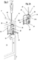
- this shows as a whole with the reference number 11, an embodiment example of an anchoring group according to the invention comprising a pair of hidden hanging-bracket devices adjustable from above, for the wall assembly of a wall cupboard.
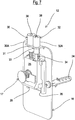
- said anchoring group 11 comprises a pair of hanging-bracket devices 12, of the adjustable type and suitable for being assembled on a wall or panel 23 by means of fixing dowels 24.
- a pair of supporting plates 22 are provided at the rear of a wall cupboard P, in a hidden position, in contact with a lining 13, constrained laterally to a shoulder 14 and above a top 15 of the wall cupboard P. It is immediately evident that the hanging bracket or its mechanisms can be produced in various alternative embodiments.
- each hanging bracket device 12 comprises an anchoring base or plate element 16 and a hooking element 17.
- the plate element 16 is provided with at least a pair of holes 60 suitable for receiving the fixing dowels 24, produced in opposite parts of the plate element 16 itself, for constraining it to the wall 23.
- Each hooking element 17 of each hanging bracket 12 is coupled in the front with the same plate element 16 to receive and constrain each supporting plate 22 which is fixed at the rear of the wall cupboard P.
- said fixing is effected thanks to the presence, in each supporting plate 22, of holes 61 formed on side edges 62 and upper edges (if present) of each plate 22 which are juxtaposed with respect to the shoulder 14 and top 15 and constrained by means of screws for obtaining its stable positioning.
- Each hanging bracket 12 comprises a slide 25, sliding linearly with respect to the plate element or flange 16 in a first direction F, whereas the hooking element 17 is at least partly associated with the slide 25.
- the hooking element 17 is in fact movable with respect to the slide 25 in at least a second direction F1, substantially perpendicular with respect to the first direction.
- Each plate element or flange 16 also comprises at least two sliding rails 26 which cooperate with the relative slide 25.
- the slide 25 provides sliding guides 27 destined for cooperating with the respective rails 26 for guiding the sliding of the slide 25 in the first direction, preferably in a vertical direction in an assembled condition.
- the anchoring group comprises regulation means for controlling the sliding of the slide 25 with respect to the plate element or flange 16.
- Said means preferably comprise: a threaded seat 28 formed in the slide 25, an abutment flap 29, having a pair of holes and integral with the plate element 16 and which extends perpendicularly to the rails 26, and a regulation screw 30, accessible and operable from above, cooperating with the abutment flap 29 and with the threaded seat 28.
- This cooperation is such as to allow the sliding of the slide 25 in the above-mentioned first direction F.
- the regulation screw 30 is kept firmly in position with respect to the abutment flap 29, but rotates, thanks to the provision of a blocking ring 31 such as a Seeger ring, which is housed in an annular seat 31A formed below its head 30A which is therefore firmly constrained to the flap 29, but free to rotate.
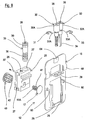
- each hanging-bracket device 12 comprises activation means for controlling the movement of the hooking element 17 in the second direction F1.
- said activation means comprise a drive screw 32, accessible and operable from above, at least partly housed in the slide 25 and positioned parallelly to the regulation screw 30.
- Said drive screw 32 is also kept firmly in position with respect to the abutment flap 29, but rotates, thanks to the provision of a blocking ring 33, such as a Seeger ring, which is housed in an annular seat 33A formed below its head 32A which is thus firmly constrained to the flap 29, but free to rotate.
- said activation means in addition to comprising in this example the drive screw 32, having a polygonal stem 34, for example hexagonal, provide a cylindrical element 35, provided externally with a portion in the form of a worm-screw 36, and housed in the slide 25, kept rotatingly in position by a pin 37.
- the cylindrical element 35 is internally and axially provided with a cavity 38, having a polygonal form complementary to that of the stem 34 of the drive screw 32.
- Said cavity 38 is also provided in both the head of the regulation screw 30 and in the head of the drive screw 32 for receiving, as described hereunder, the tip of a screwdriver or rotation key.
- the pin 37 is inserted, in an assembled condition, in the slide 25 and then also in the throat 39 of the cylindrical element 35.
- the portion in the form of a worm screw 36 of the cylindrical element 35 cooperates with a toothed wheel 40, also housed in the slide 25 and rotatingly withheld with respect to the same.
- the hooking element 17 is provided with a partially threaded body 41 cooperating with a threaded seat 42 inside the toothed wheel 40.
- the body 41 has two smooth opposite planes (or flat portions) (41A) that slide inside complementary guiding seats of a hole of the slide 25.
- the body 41 of the hooking element 17 can be moved horizontally, in an extraction/insertion direction according to the arrow F1, from the toothed wheel 40 following the rotation of the latter, when activated by the portion in the form of a worm screw 36 of the cylindrical element 35.
- the axes of the portion in the form of a worm screw 36 of the cylindrical element 35, of the drive screw 32 and screw 30 are parallel to each other, so that access by means of keys or screwdrivers for effecting regulations of the wall cupboard P can be obtained by acting from the same part, i.e. directly from above.
- the constraint of the hanging brackets 12 to the wall 23 allows a safe and stable positioning of the anchoring group, avoiding any possible breakage of the wooden parts or breakage points.
- the horizontal or vertical movement of the wall cupboard P can be advantageously regulated, acting on only one side, i.e. from above, and by simply acting with a screwdriver 45.
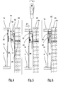
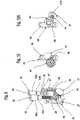
- FIGs 2, 2A and 3, 3A show how accessibility to the hanging bracket 12 is achieved through the screwdriver 45 introduced from above alternatively in either of the two holes 43 of the top 15 of the wall cupboard P.
- each hanging bracket 12 is constrained to the wall 23 thus creating an increased capacity which prevents any possible sagging also in the case of a considerable load. Furthermore, each supporting plate 22 collaborating with the respective hooking element 17 of the hanging bracket 12 is firmly positioned on the rear part of the cupboard without any holing, for example in correspondence with the convergence between the top 15 and the shoulder 14, in a particularly resistant point of the structure of the wall cupboard P.
- Figure 5 shows by way of example how the screwdriver 45 is introduced from above into one of the holes 43 of the top 15 to effect the adjustment in a horizontal direction, i.e. in depth, according to the arrow F1, after juxtaposing the wall cupboard P with relative supporting plates 22 and the respective hooking element 17 of the corresponding hanging brackets 12, as indicated by the arrow K in the section of figure 4 .
- figure 6 shows how the wall cupboard P has been perfectly regulated in position by moving it as required towards the wall 23.
- an anchoring group has been provided in which the hanging bracket is fixed to the wall or panel with respect to which the wall cupboard P, bearing anchoring supports such as plates or a single bar, must be positioned, optimizing the stable and safe positioning of the wall cupboard also in the presence of particularly thin panels of the top, shoulder and base.
- each anchoring group comprises regulation means and activation means of the reciprocal position between the hanging-bracket device 12, the hooking element 17 and the anchoring support 22 to effect a regulation in the position of the wall cupboard P with respect to the wall 23.
- Said regulation is effected in two directions F, F1, perpendicular to each other, vertically (in height) and in horizontally (in depth) respectively and the regulation and activation are advantageously effected from above.
Landscapes
- Connection Of Plates (AREA)
- Furniture Connections (AREA)
Claims (9)
- Groupe d'ancrage ajustable pour l'ensemble mural (23) de placards muraux (P) comprenant un dispositif de crochet de suspension (12), comportant une base d'ancrage (16) à un panneau ou mur (23) et un élément d'accrochage (17), et un support d'ancrage (22) à un placard mural (P), des moyens de régulation et des moyens d'activation de la position réciproque étant prévus entre ledit dispositif de crochet de suspension (12), ledit élément d'accrochage (17) et ledit support d'ancrage (22) afin de réguler la position du placard mural (P) par rapport au mur (23) selon deux directions (F, F1) perpendiculaires l'une à l'autre, verticalement (en hauteur) et horizontalement (en profondeur), respectivement, lesdits moyens de régulation et lesdits moyens d'activation étant tous les deux accessibles par le dessus à l'aide de trous (43) ménagés dans une partie supérieure (15) du placard mural (P), ledit crochet de suspension (12) comprenant un coulisseau (25) coulissant de manière linéaire par rapport à ladite base d'ancrage (16) dans une première direction, ledit élément d'accrochage (17) étant au moins partiellement associé audit coulisseau (25) et mobile par rapport à ce dernier dans au moins une seconde direction sensiblement perpendiculaire à ladite première direction, lesdits moyens de régulation et lesdits moyens d'activation étant respectivement associés audit coulisseau (25) et audit élément d'accrochage (17), et
lesdits moyens de régulation comprenant : un siège fileté (28) ménagé dans ledit coulisseau (25), un rabat de butée (29) solidaire de ladite base (16) qui s'étend perpendiculairement à la direction de déplacement dudit coulisseau, et une vis de régulation (30) coopérant avec ledit rabat de butée (29) et avec ledit siège fileté (28) pour permettre le coulissement dudit coulisseau (25) dans ladite première direction,
caractérisé par le fait que ladite vis de régulation (30) est maintenue fermement en position par rapport au rabat de butée (29), mais tourne, grâce à la disposition d'un anneau de blocage (31) qui est logé dans un siège annulaire (31A) situé sous une tête (30A) de ladite vis de régulation (30) et au-dessus du rabat de butée (29). - Groupe selon la revendication 1, caractérisé par le fait que ladite base (16) comprend des trous de fixation (60), pour recevoir des goujons de fixation audit mur (23), et des rails de coulissement (26) dudit coulisseau (25), et ledit coulisseau (25) comprend des guides de coulissement (27), lesdits rails (26) et lesdits guides (27) étant appropriés pour coopérer les uns avec les autres pour guider le coulissement dudit coulisseau (25) dans au moins une première direction.
- Groupe selon la revendication 1 ou 2, caractérisé par le fait que lesdits moyens de régulation accessibles par le dessus sont appropriés pour commander le coulissement dudit coulisseau (25) par rapport à ladite base (16).
- Groupe selon une ou plusieurs des revendications 1 à 3, caractérisé par le fait que lesdits moyens d'activation accessibles par le dessus sont appropriés pour commander ledit mouvement dudit élément d'accrochage (17) dans ladite seconde direction.
- Groupe d'ancrage ajustable pour l'ensemble mural (23) de placards muraux (P) comprenant un dispositif de crochet de suspension (12), comportant une base d'ancrage (16) à un panneau ou mur (23) et un élément d'accrochage (17), et un support d'ancrage (22) à un placard mural (P), des moyens de régulation et des moyens d'activation de la position réciproque étant prévus entre ledit dispositif de crochet de suspension (12), ledit élément d'accrochage (17) et ledit support d'ancrage (22) afin de réguler la position du placard mural (P) par rapport au mur (23) selon deux directions (F, F1) perpendiculaires l'une à l'autre, verticalement (en hauteur) et horizontalement (en profondeur), respectivement, lesdits moyens de régulation et lesdits moyens d'activation étant tous les deux accessibles par le dessus à l'aide de trous (43) ménagés dans une partie supérieure (15) du placard mural (P), ledit crochet de suspension (12) comprenant un coulisseau (25) coulissant de manière linéaire par rapport à ladite base d'ancrage (16) dans une première direction, ledit élément d'accrochage (17) étant au moins partiellement associé audit coulisseau (25) et mobile par rapport à ce dernier dans au moins une seconde direction sensiblement perpendiculaire à ladite première direction, lesdits moyens de régulation et lesdits moyens d'activation étant respectivement associés audit coulisseau (25) et audit élément d'accrochage (17), et lesdits moyens d'activation comprenant une vis d'entraînement (32) au moins partiellement logée dans ledit coulisseau (25), ladite vis d'entraînement (32) étant disposée parallèlement à une vis de régulation (30), caractérisé par le fait que ladite vis d'entraînement (32) est maintenue fermement en position par rapport à un rabat de butée (29) de ladite base (16), mais tourne, grâce à la disposition d'un anneau de blocage (33) qui est logé dans un siège annulaire (33A) situé sous une tête (32A) de ladite vis d'entraînement (32) et au-dessus du rabat de butée (29).
- Groupe selon la revendication 5, caractérisé par le fait que ladite vis d'entraînement (32) comporte une tige polygonale (34) qui s'étend en engagement à l'intérieur d'un élément cylindrique (35) qui, à son tour, comporte extérieurement une partie sous la forme d'une vis sans fin (36) qui est engagée avec une roue dentée (40), ledit élément cylindrique (35) et ladite roue dentée (40) étant logés dans le coulisseau (25) libres de tourner, ledit élément d'accrochage (17) comportant un corps partiellement fileté (41) coopérant avec un siège fileté (42) à l'intérieur de la roue dentée (40) de façon à se déplacer dans ladite seconde direction.
- Groupe selon la revendication 6, caractérisé par le fait que ledit corps fileté (41) a deux plans opposés lisses (ou parties plates) (41A) qui coulissent à l'intérieur de sièges de guidage complémentaires d'un trou du coulisseau (25) de telle sorte que ledit élément d'accrochage (17) peut être déplacé horizontalement, dans une direction d'extraction/introduction depuis la roue dentée (40) à la suite de la rotation de cette dernière.
- Groupe selon une ou plusieurs des revendications précédentes, caractérisé par le fait que ledit support d'ancrage positionné derrière ledit placard mural (P) est une unique barre.
- Groupe selon une ou plusieurs des revendications 1 à 8, caractérisé par le fait que ledit support d'ancrage positionné derrière ledit placard mural (P) consiste en une paire de plaques de support (22).
Priority Applications (1)
| Application Number | Priority Date | Filing Date | Title |
|---|---|---|---|
| PL16745079T PL3328246T3 (pl) | 2015-07-29 | 2016-07-20 | Grupa kotwiąca dla szafek ściennych o zwiększonej nośności z regulacją od góry |
Applications Claiming Priority (2)
| Application Number | Priority Date | Filing Date | Title |
|---|---|---|---|
| ITUB2015A002604A ITUB20152604A1 (it) | 2015-07-29 | 2015-07-29 | Gruppo di ancoraggio per mobili pensili a portata maggiorata con regolazione dall’alto |
| PCT/EP2016/067303 WO2017016955A1 (fr) | 2015-07-29 | 2016-07-20 | Groupe d'ancrage pour placards muraux avec une capacité accrue avec régulation par le dessus |
Publications (2)
| Publication Number | Publication Date |
|---|---|
| EP3328246A1 EP3328246A1 (fr) | 2018-06-06 |
| EP3328246B1 true EP3328246B1 (fr) | 2019-09-25 |
Family
ID=54329964
Family Applications (1)
| Application Number | Title | Priority Date | Filing Date |
|---|---|---|---|
| EP16745079.0A Active EP3328246B1 (fr) | 2015-07-29 | 2016-07-20 | Groupe d'ancrage pour placards muraux avec une capacité accrue avec régulation par le dessus |
Country Status (5)
| Country | Link |
|---|---|
| EP (1) | EP3328246B1 (fr) |
| ES (1) | ES2760975T3 (fr) |
| IT (1) | ITUB20152604A1 (fr) |
| PL (1) | PL3328246T3 (fr) |
| WO (1) | WO2017016955A1 (fr) |
Family Cites Families (1)
| Publication number | Priority date | Publication date | Assignee | Title |
|---|---|---|---|---|
| ITMI20110591A1 (it) * | 2011-04-11 | 2012-10-12 | Leonardo Srl | Gruppo di ancoraggio per mobili pensili con regolazione dall'alto |
-
2015
- 2015-07-29 IT ITUB2015A002604A patent/ITUB20152604A1/it unknown
-
2016
- 2016-07-20 PL PL16745079T patent/PL3328246T3/pl unknown
- 2016-07-20 WO PCT/EP2016/067303 patent/WO2017016955A1/fr unknown
- 2016-07-20 ES ES16745079T patent/ES2760975T3/es active Active
- 2016-07-20 EP EP16745079.0A patent/EP3328246B1/fr active Active
Non-Patent Citations (1)
| Title |
|---|
| None * |
Also Published As
| Publication number | Publication date |
|---|---|
| ITUB20152604A1 (it) | 2017-01-29 |
| ES2760975T3 (es) | 2020-05-18 |
| PL3328246T3 (pl) | 2020-03-31 |
| WO2017016955A1 (fr) | 2017-02-02 |
| EP3328246A1 (fr) | 2018-06-06 |
Similar Documents
| Publication | Publication Date | Title |
|---|---|---|
| KR101558129B1 (ko) | 미닫이용 도어프레임 | |
| EP3025619B1 (fr) | Groupe d'ancrage pour placards muraux à régulation à partir du dessus | |
| US20090289537A1 (en) | Leveling system | |
| JP2013518622A (ja) | 引き出し構造 | |
| EP3248505B1 (fr) | Dispositif d'ancrage de panneaux | |
| EP3349618B1 (fr) | Groupe d'ancrage pour placards muraux à assemblage facilité | |
| EP3328246B1 (fr) | Groupe d'ancrage pour placards muraux avec une capacité accrue avec régulation par le dessus | |
| EP2510836B1 (fr) | Structure support pour étagères murales | |
| EP2510834B1 (fr) | Dispositif caché pour ensemble de paroi d'un composant structurel d'un meuble à régulation latérale | |
| EP3328244B1 (fr) | Groupe d'ancrage pour placards muraux avec régulation par le dessous | |
| EP3328245B1 (fr) | Groupe d'ancrage pour placards muraux possédant une capacité accrue avec régulation par le dessous | |
| EP3064088A1 (fr) | Crochet de suspension caché pour l'ensemble de paroi d'un composant structurel d'un meuble, avec régulation du dessus | |
| EP3823498B1 (fr) | Dispositif de support pour structure tubulaire en porte-à-faux | |
| JP2009191562A (ja) | 物品収納什器 |
Legal Events
| Date | Code | Title | Description |
|---|---|---|---|
| STAA | Information on the status of an ep patent application or granted ep patent |
Free format text: STATUS: THE INTERNATIONAL PUBLICATION HAS BEEN MADE |
|
| PUAI | Public reference made under article 153(3) epc to a published international application that has entered the european phase |
Free format text: ORIGINAL CODE: 0009012 |
|
| STAA | Information on the status of an ep patent application or granted ep patent |
Free format text: STATUS: REQUEST FOR EXAMINATION WAS MADE |
|
| 17P | Request for examination filed |
Effective date: 20171116 |
|
| AK | Designated contracting states |
Kind code of ref document: A1 Designated state(s): AL AT BE BG CH CY CZ DE DK EE ES FI FR GB GR HR HU IE IS IT LI LT LU LV MC MK MT NL NO PL PT RO RS SE SI SK SM TR |
|
| AX | Request for extension of the european patent |
Extension state: BA ME |
|
| DAV | Request for validation of the european patent (deleted) | ||
| DAX | Request for extension of the european patent (deleted) | ||
| GRAP | Despatch of communication of intention to grant a patent |
Free format text: ORIGINAL CODE: EPIDOSNIGR1 |
|
| STAA | Information on the status of an ep patent application or granted ep patent |
Free format text: STATUS: GRANT OF PATENT IS INTENDED |
|
| INTG | Intention to grant announced |
Effective date: 20190502 |
|
| GRAS | Grant fee paid |
Free format text: ORIGINAL CODE: EPIDOSNIGR3 |
|
| GRAA | (expected) grant |
Free format text: ORIGINAL CODE: 0009210 |
|
| STAA | Information on the status of an ep patent application or granted ep patent |
Free format text: STATUS: THE PATENT HAS BEEN GRANTED |
|
| AK | Designated contracting states |
Kind code of ref document: B1 Designated state(s): AL AT BE BG CH CY CZ DE DK EE ES FI FR GB GR HR HU IE IS IT LI LT LU LV MC MK MT NL NO PL PT RO RS SE SI SK SM TR |
|
| REG | Reference to a national code |
Ref country code: GB Ref legal event code: FG4D |
|
| REG | Reference to a national code |
Ref country code: CH Ref legal event code: EP |
|
| REG | Reference to a national code |
Ref country code: AT Ref legal event code: REF Ref document number: 1182958 Country of ref document: AT Kind code of ref document: T Effective date: 20191015 |
|
| REG | Reference to a national code |
Ref country code: IE Ref legal event code: FG4D |
|
| REG | Reference to a national code |
Ref country code: DE Ref legal event code: R096 Ref document number: 602016021273 Country of ref document: DE |
|
| REG | Reference to a national code |
Ref country code: NL Ref legal event code: MP Effective date: 20190925 |
|
| PG25 | Lapsed in a contracting state [announced via postgrant information from national office to epo] |
Ref country code: NO Free format text: LAPSE BECAUSE OF FAILURE TO SUBMIT A TRANSLATION OF THE DESCRIPTION OR TO PAY THE FEE WITHIN THE PRESCRIBED TIME-LIMIT Effective date: 20191225 Ref country code: FI Free format text: LAPSE BECAUSE OF FAILURE TO SUBMIT A TRANSLATION OF THE DESCRIPTION OR TO PAY THE FEE WITHIN THE PRESCRIBED TIME-LIMIT Effective date: 20190925 Ref country code: SE Free format text: LAPSE BECAUSE OF FAILURE TO SUBMIT A TRANSLATION OF THE DESCRIPTION OR TO PAY THE FEE WITHIN THE PRESCRIBED TIME-LIMIT Effective date: 20190925 Ref country code: HR Free format text: LAPSE BECAUSE OF FAILURE TO SUBMIT A TRANSLATION OF THE DESCRIPTION OR TO PAY THE FEE WITHIN THE PRESCRIBED TIME-LIMIT Effective date: 20190925 Ref country code: LT Free format text: LAPSE BECAUSE OF FAILURE TO SUBMIT A TRANSLATION OF THE DESCRIPTION OR TO PAY THE FEE WITHIN THE PRESCRIBED TIME-LIMIT Effective date: 20190925 Ref country code: BG Free format text: LAPSE BECAUSE OF FAILURE TO SUBMIT A TRANSLATION OF THE DESCRIPTION OR TO PAY THE FEE WITHIN THE PRESCRIBED TIME-LIMIT Effective date: 20191225 |
|
| REG | Reference to a national code |
Ref country code: LT Ref legal event code: MG4D |
|
| PG25 | Lapsed in a contracting state [announced via postgrant information from national office to epo] |
Ref country code: LV Free format text: LAPSE BECAUSE OF FAILURE TO SUBMIT A TRANSLATION OF THE DESCRIPTION OR TO PAY THE FEE WITHIN THE PRESCRIBED TIME-LIMIT Effective date: 20190925 Ref country code: RS Free format text: LAPSE BECAUSE OF FAILURE TO SUBMIT A TRANSLATION OF THE DESCRIPTION OR TO PAY THE FEE WITHIN THE PRESCRIBED TIME-LIMIT Effective date: 20190925 Ref country code: GR Free format text: LAPSE BECAUSE OF FAILURE TO SUBMIT A TRANSLATION OF THE DESCRIPTION OR TO PAY THE FEE WITHIN THE PRESCRIBED TIME-LIMIT Effective date: 20191226 |
|
| REG | Reference to a national code |
Ref country code: AT Ref legal event code: MK05 Ref document number: 1182958 Country of ref document: AT Kind code of ref document: T Effective date: 20190925 |
|
| PG25 | Lapsed in a contracting state [announced via postgrant information from national office to epo] |
Ref country code: RO Free format text: LAPSE BECAUSE OF FAILURE TO SUBMIT A TRANSLATION OF THE DESCRIPTION OR TO PAY THE FEE WITHIN THE PRESCRIBED TIME-LIMIT Effective date: 20190925 Ref country code: PT Free format text: LAPSE BECAUSE OF FAILURE TO SUBMIT A TRANSLATION OF THE DESCRIPTION OR TO PAY THE FEE WITHIN THE PRESCRIBED TIME-LIMIT Effective date: 20200127 Ref country code: NL Free format text: LAPSE BECAUSE OF FAILURE TO SUBMIT A TRANSLATION OF THE DESCRIPTION OR TO PAY THE FEE WITHIN THE PRESCRIBED TIME-LIMIT Effective date: 20190925 Ref country code: AT Free format text: LAPSE BECAUSE OF FAILURE TO SUBMIT A TRANSLATION OF THE DESCRIPTION OR TO PAY THE FEE WITHIN THE PRESCRIBED TIME-LIMIT Effective date: 20190925 Ref country code: EE Free format text: LAPSE BECAUSE OF FAILURE TO SUBMIT A TRANSLATION OF THE DESCRIPTION OR TO PAY THE FEE WITHIN THE PRESCRIBED TIME-LIMIT Effective date: 20190925 Ref country code: AL Free format text: LAPSE BECAUSE OF FAILURE TO SUBMIT A TRANSLATION OF THE DESCRIPTION OR TO PAY THE FEE WITHIN THE PRESCRIBED TIME-LIMIT Effective date: 20190925 |
|
| REG | Reference to a national code |
Ref country code: ES Ref legal event code: FG2A Ref document number: 2760975 Country of ref document: ES Kind code of ref document: T3 Effective date: 20200518 |
|
| PG25 | Lapsed in a contracting state [announced via postgrant information from national office to epo] |
Ref country code: IS Free format text: LAPSE BECAUSE OF FAILURE TO SUBMIT A TRANSLATION OF THE DESCRIPTION OR TO PAY THE FEE WITHIN THE PRESCRIBED TIME-LIMIT Effective date: 20200224 Ref country code: CZ Free format text: LAPSE BECAUSE OF FAILURE TO SUBMIT A TRANSLATION OF THE DESCRIPTION OR TO PAY THE FEE WITHIN THE PRESCRIBED TIME-LIMIT Effective date: 20190925 Ref country code: SM Free format text: LAPSE BECAUSE OF FAILURE TO SUBMIT A TRANSLATION OF THE DESCRIPTION OR TO PAY THE FEE WITHIN THE PRESCRIBED TIME-LIMIT Effective date: 20190925 Ref country code: SK Free format text: LAPSE BECAUSE OF FAILURE TO SUBMIT A TRANSLATION OF THE DESCRIPTION OR TO PAY THE FEE WITHIN THE PRESCRIBED TIME-LIMIT Effective date: 20190925 |
|
| REG | Reference to a national code |
Ref country code: DE Ref legal event code: R097 Ref document number: 602016021273 Country of ref document: DE |
|
| PG2D | Information on lapse in contracting state deleted |
Ref country code: IS |
|
| PG25 | Lapsed in a contracting state [announced via postgrant information from national office to epo] |
Ref country code: DK Free format text: LAPSE BECAUSE OF FAILURE TO SUBMIT A TRANSLATION OF THE DESCRIPTION OR TO PAY THE FEE WITHIN THE PRESCRIBED TIME-LIMIT Effective date: 20190925 Ref country code: IS Free format text: LAPSE BECAUSE OF FAILURE TO SUBMIT A TRANSLATION OF THE DESCRIPTION OR TO PAY THE FEE WITHIN THE PRESCRIBED TIME-LIMIT Effective date: 20200126 |
|
| PLBE | No opposition filed within time limit |
Free format text: ORIGINAL CODE: 0009261 |
|
| STAA | Information on the status of an ep patent application or granted ep patent |
Free format text: STATUS: NO OPPOSITION FILED WITHIN TIME LIMIT |
|
| 26N | No opposition filed |
Effective date: 20200626 |
|
| PG25 | Lapsed in a contracting state [announced via postgrant information from national office to epo] |
Ref country code: SI Free format text: LAPSE BECAUSE OF FAILURE TO SUBMIT A TRANSLATION OF THE DESCRIPTION OR TO PAY THE FEE WITHIN THE PRESCRIBED TIME-LIMIT Effective date: 20190925 |
|
| PG25 | Lapsed in a contracting state [announced via postgrant information from national office to epo] |
Ref country code: MC Free format text: LAPSE BECAUSE OF FAILURE TO SUBMIT A TRANSLATION OF THE DESCRIPTION OR TO PAY THE FEE WITHIN THE PRESCRIBED TIME-LIMIT Effective date: 20190925 |
|
| REG | Reference to a national code |
Ref country code: CH Ref legal event code: PL |
|
| GBPC | Gb: european patent ceased through non-payment of renewal fee |
Effective date: 20200720 |
|
| REG | Reference to a national code |
Ref country code: BE Ref legal event code: MM Effective date: 20200731 |
|
| PG25 | Lapsed in a contracting state [announced via postgrant information from national office to epo] |
Ref country code: CH Free format text: LAPSE BECAUSE OF NON-PAYMENT OF DUE FEES Effective date: 20200731 Ref country code: LU Free format text: LAPSE BECAUSE OF NON-PAYMENT OF DUE FEES Effective date: 20200720 Ref country code: LI Free format text: LAPSE BECAUSE OF NON-PAYMENT OF DUE FEES Effective date: 20200731 Ref country code: GB Free format text: LAPSE BECAUSE OF NON-PAYMENT OF DUE FEES Effective date: 20200720 |
|
| PG25 | Lapsed in a contracting state [announced via postgrant information from national office to epo] |
Ref country code: BE Free format text: LAPSE BECAUSE OF NON-PAYMENT OF DUE FEES Effective date: 20200731 |
|
| PG25 | Lapsed in a contracting state [announced via postgrant information from national office to epo] |
Ref country code: IE Free format text: LAPSE BECAUSE OF NON-PAYMENT OF DUE FEES Effective date: 20200720 |
|
| PG25 | Lapsed in a contracting state [announced via postgrant information from national office to epo] |
Ref country code: TR Free format text: LAPSE BECAUSE OF FAILURE TO SUBMIT A TRANSLATION OF THE DESCRIPTION OR TO PAY THE FEE WITHIN THE PRESCRIBED TIME-LIMIT Effective date: 20190925 Ref country code: MT Free format text: LAPSE BECAUSE OF FAILURE TO SUBMIT A TRANSLATION OF THE DESCRIPTION OR TO PAY THE FEE WITHIN THE PRESCRIBED TIME-LIMIT Effective date: 20190925 Ref country code: CY Free format text: LAPSE BECAUSE OF FAILURE TO SUBMIT A TRANSLATION OF THE DESCRIPTION OR TO PAY THE FEE WITHIN THE PRESCRIBED TIME-LIMIT Effective date: 20190925 |
|
| PG25 | Lapsed in a contracting state [announced via postgrant information from national office to epo] |
Ref country code: MK Free format text: LAPSE BECAUSE OF FAILURE TO SUBMIT A TRANSLATION OF THE DESCRIPTION OR TO PAY THE FEE WITHIN THE PRESCRIBED TIME-LIMIT Effective date: 20190925 |
|
| P01 | Opt-out of the competence of the unified patent court (upc) registered |
Effective date: 20230610 |
|
| PGFP | Annual fee paid to national office [announced via postgrant information from national office to epo] |
Ref country code: IT Payment date: 20230720 Year of fee payment: 8 Ref country code: ES Payment date: 20230804 Year of fee payment: 8 |
|
| PGFP | Annual fee paid to national office [announced via postgrant information from national office to epo] |
Ref country code: PL Payment date: 20230704 Year of fee payment: 8 Ref country code: FR Payment date: 20230725 Year of fee payment: 8 Ref country code: DE Payment date: 20230727 Year of fee payment: 8 |