EP2899337A1 - Lock system - Google Patents
Lock system Download PDFInfo
- Publication number
- EP2899337A1 EP2899337A1 EP14189590.4A EP14189590A EP2899337A1 EP 2899337 A1 EP2899337 A1 EP 2899337A1 EP 14189590 A EP14189590 A EP 14189590A EP 2899337 A1 EP2899337 A1 EP 2899337A1
- Authority
- EP
- European Patent Office
- Prior art keywords
- sidebar
- key
- blocking member
- lock
- keyway
- Prior art date
- Legal status (The legal status is an assumption and is not a legal conclusion. Google has not performed a legal analysis and makes no representation as to the accuracy of the status listed.)
- Granted
Links
- 230000000903 blocking effect Effects 0.000 claims abstract description 63
- 230000000669 biting effect Effects 0.000 claims abstract description 9
- 238000003780 insertion Methods 0.000 claims abstract description 8
- 230000037431 insertion Effects 0.000 claims abstract description 8
- 230000004888 barrier function Effects 0.000 claims abstract description 7
- 230000004048 modification Effects 0.000 description 4
- 238000012986 modification Methods 0.000 description 4
- 230000035515 penetration Effects 0.000 description 3
- 230000007246 mechanism Effects 0.000 description 2
- 230000004308 accommodation Effects 0.000 description 1
- 238000007792 addition Methods 0.000 description 1
- 238000004891 communication Methods 0.000 description 1
- 238000010276 construction Methods 0.000 description 1
- 230000000694 effects Effects 0.000 description 1
- 230000000717 retained effect Effects 0.000 description 1
Images


Classifications
-
- E—FIXED CONSTRUCTIONS
- E05—LOCKS; KEYS; WINDOW OR DOOR FITTINGS; SAFES
- E05B—LOCKS; ACCESSORIES THEREFOR; HANDCUFFS
- E05B27/00—Cylinder locks or other locks with tumbler pins or balls that are set by pushing the key in
- E05B27/0003—Details
-
- E—FIXED CONSTRUCTIONS
- E05—LOCKS; KEYS; WINDOW OR DOOR FITTINGS; SAFES
- E05B—LOCKS; ACCESSORIES THEREFOR; HANDCUFFS
- E05B19/00—Keys; Accessories therefor
-
- E—FIXED CONSTRUCTIONS
- E05—LOCKS; KEYS; WINDOW OR DOOR FITTINGS; SAFES
- E05B—LOCKS; ACCESSORIES THEREFOR; HANDCUFFS
- E05B19/00—Keys; Accessories therefor
- E05B19/0017—Key profiles
- E05B19/0041—Key profiles characterized by the cross-section of the key blade in a plane perpendicular to the longitudinal axis of the key
- E05B19/007—Key profiles characterized by the cross-section of the key blade in a plane perpendicular to the longitudinal axis of the key with U- or V-shaped cross-section
-
- E—FIXED CONSTRUCTIONS
- E05—LOCKS; KEYS; WINDOW OR DOOR FITTINGS; SAFES
- E05B—LOCKS; ACCESSORIES THEREFOR; HANDCUFFS
- E05B19/00—Keys; Accessories therefor
- E05B19/18—Keys adjustable before use
-
- E—FIXED CONSTRUCTIONS
- E05—LOCKS; KEYS; WINDOW OR DOOR FITTINGS; SAFES
- E05B—LOCKS; ACCESSORIES THEREFOR; HANDCUFFS
- E05B27/00—Cylinder locks or other locks with tumbler pins or balls that are set by pushing the key in
- E05B27/0042—Cylinder locks or other locks with tumbler pins or balls that are set by pushing the key in with additional key identifying function, e.g. with use of additional key operated rotor-blocking elements, not of split pin tumbler type
-
- E—FIXED CONSTRUCTIONS
- E05—LOCKS; KEYS; WINDOW OR DOOR FITTINGS; SAFES
- E05B—LOCKS; ACCESSORIES THEREFOR; HANDCUFFS
- E05B27/00—Cylinder locks or other locks with tumbler pins or balls that are set by pushing the key in
- E05B27/0057—Cylinder locks or other locks with tumbler pins or balls that are set by pushing the key in with increased picking resistance
-
- E—FIXED CONSTRUCTIONS
- E05—LOCKS; KEYS; WINDOW OR DOOR FITTINGS; SAFES
- E05B—LOCKS; ACCESSORIES THEREFOR; HANDCUFFS
- E05B27/00—Cylinder locks or other locks with tumbler pins or balls that are set by pushing the key in
- E05B27/0082—Side bar locking
-
- E—FIXED CONSTRUCTIONS
- E05—LOCKS; KEYS; WINDOW OR DOOR FITTINGS; SAFES
- E05B—LOCKS; ACCESSORIES THEREFOR; HANDCUFFS
- E05B27/00—Cylinder locks or other locks with tumbler pins or balls that are set by pushing the key in
- E05B27/02—Cylinder locks or other locks with tumbler pins or balls that are set by pushing the key in operated by the edge of the key
- E05B27/08—Cylinder locks or other locks with tumbler pins or balls that are set by pushing the key in operated by the edge of the key arranged axially
-
- E—FIXED CONSTRUCTIONS
- E05—LOCKS; KEYS; WINDOW OR DOOR FITTINGS; SAFES
- E05B—LOCKS; ACCESSORIES THEREFOR; HANDCUFFS
- E05B35/00—Locks for use with special keys or a plurality of keys ; keys therefor
- E05B35/14—Locks for use with special keys or a plurality of keys ; keys therefor with keys of which different parts operate separate mechanisms
-
- Y—GENERAL TAGGING OF NEW TECHNOLOGICAL DEVELOPMENTS; GENERAL TAGGING OF CROSS-SECTIONAL TECHNOLOGIES SPANNING OVER SEVERAL SECTIONS OF THE IPC; TECHNICAL SUBJECTS COVERED BY FORMER USPC CROSS-REFERENCE ART COLLECTIONS [XRACs] AND DIGESTS
- Y10—TECHNICAL SUBJECTS COVERED BY FORMER USPC
- Y10T—TECHNICAL SUBJECTS COVERED BY FORMER US CLASSIFICATION
- Y10T70/00—Locks
- Y10T70/70—Operating mechanism
- Y10T70/7441—Key
- Y10T70/7486—Single key
- Y10T70/7508—Tumbler type
- Y10T70/752—Sliding tumblers
- Y10T70/7531—Transverse
-
- Y—GENERAL TAGGING OF NEW TECHNOLOGICAL DEVELOPMENTS; GENERAL TAGGING OF CROSS-SECTIONAL TECHNOLOGIES SPANNING OVER SEVERAL SECTIONS OF THE IPC; TECHNICAL SUBJECTS COVERED BY FORMER USPC CROSS-REFERENCE ART COLLECTIONS [XRACs] AND DIGESTS
- Y10—TECHNICAL SUBJECTS COVERED BY FORMER USPC
- Y10T—TECHNICAL SUBJECTS COVERED BY FORMER US CLASSIFICATION
- Y10T70/00—Locks
- Y10T70/70—Operating mechanism
- Y10T70/7441—Key
- Y10T70/7486—Single key
- Y10T70/7508—Tumbler type
- Y10T70/7559—Cylinder type
- Y10T70/7588—Rotary plug
- Y10T70/7593—Sliding tumblers
- Y10T70/7599—Transverse of plug
- Y10T70/7616—Including sidebar
-
- Y—GENERAL TAGGING OF NEW TECHNOLOGICAL DEVELOPMENTS; GENERAL TAGGING OF CROSS-SECTIONAL TECHNOLOGIES SPANNING OVER SEVERAL SECTIONS OF THE IPC; TECHNICAL SUBJECTS COVERED BY FORMER USPC CROSS-REFERENCE ART COLLECTIONS [XRACs] AND DIGESTS
- Y10—TECHNICAL SUBJECTS COVERED BY FORMER USPC
- Y10T—TECHNICAL SUBJECTS COVERED BY FORMER US CLASSIFICATION
- Y10T70/00—Locks
- Y10T70/70—Operating mechanism
- Y10T70/7441—Key
- Y10T70/7486—Single key
- Y10T70/7508—Tumbler type
- Y10T70/7559—Cylinder type
- Y10T70/7588—Rotary plug
- Y10T70/7593—Sliding tumblers
- Y10T70/7621—Including sidebar
-
- Y—GENERAL TAGGING OF NEW TECHNOLOGICAL DEVELOPMENTS; GENERAL TAGGING OF CROSS-SECTIONAL TECHNOLOGIES SPANNING OVER SEVERAL SECTIONS OF THE IPC; TECHNICAL SUBJECTS COVERED BY FORMER USPC CROSS-REFERENCE ART COLLECTIONS [XRACs] AND DIGESTS
- Y10—TECHNICAL SUBJECTS COVERED BY FORMER USPC
- Y10T—TECHNICAL SUBJECTS COVERED BY FORMER US CLASSIFICATION
- Y10T70/00—Locks
- Y10T70/70—Operating mechanism
- Y10T70/7441—Key
- Y10T70/778—Operating elements
- Y10T70/7791—Keys
- Y10T70/7836—Plural shanks, stems or bit wings
-
- Y—GENERAL TAGGING OF NEW TECHNOLOGICAL DEVELOPMENTS; GENERAL TAGGING OF CROSS-SECTIONAL TECHNOLOGIES SPANNING OVER SEVERAL SECTIONS OF THE IPC; TECHNICAL SUBJECTS COVERED BY FORMER USPC CROSS-REFERENCE ART COLLECTIONS [XRACs] AND DIGESTS
- Y10—TECHNICAL SUBJECTS COVERED BY FORMER USPC
- Y10T—TECHNICAL SUBJECTS COVERED BY FORMER US CLASSIFICATION
- Y10T70/00—Locks
- Y10T70/70—Operating mechanism
- Y10T70/7441—Key
- Y10T70/778—Operating elements
- Y10T70/7791—Keys
- Y10T70/7881—Bitting
Definitions
- the present invention relates to locks, keys and lock systems.
- the lock comprises a central core or plug and an outer housing or shell, in which the core rotates, the housing being mounted in a suitable latch structure.
- core and housing will be used in this context.
- the present invention may be applied to any type of latch structure for which pin tumbler and related locks are used, for example, cam locks, door locks, phone locks and security fittings.
- a lock system including:
- the position of the notch on the sidebar blocking member can be selected from a number of possible positions, the selected position dictating the required length which the corresponding unblocking member is required to operatively protrude from the key handle in order to align the selected notch position with the opening.
- a lock a key and a key handle, each having features which are adapted to be employed in the lock system.
- a lock 110 has a core 112 received in a longitudinal cavity 116 of a housing 118.
- the core 112 has a keyway 119 and a plurality of guide bores 120 aligned with the keyway 119 and receptive locking pins 122.
- a face plate 123 is located at the end face of the core 112.
- the locking pins 122 are inwardly biased in the guide bores 120 by springs 125 and a cover plate 127 as per the original BILOCKTM design.
- the core 112 features a longitudinally disposed sidebar recess 124 for the accommodation of sidebars 126.
- the sidebar recess 124 is in communication with the guide bores 120.
- the sidebars 126 feature a series of inwardly extending protrusions 128 in the shape of pins and are biased away from the guide bores 120 by sidebar springs 129 or other biasing means as known in the art.
- the body of the core 112 is flattened on either side to provide a suitable means for interacting with a latch mechanism (not shown).
- the longitudinal slots 130 are shaped to receive the sidebars 126, which are biased theretowards.
- Each locking pin 122 is provided with a hole 136.
- the holes 136 correspond to locking combinations for the lock dictated by the relative position of the hole 136 along the height of the locking pin 122.
- a key 140 is provided by bitings 142 cut on the key blade 144.
- the bitings 142 move the locking pins 122 a corresponding height along the respective guide bores 120.
- a correctly coded key moves the locking pins 122 so that the respective holes 136 are aligned with the sidebar recess 124 and are capable of receiving the inwardly extending protrusions 128 of the sidebars 126 when the sidebars 126 are caused to move against their bias inwardly.
- the core 112 includes a channel 150 which extends longitudinally alongside the keyway 119 and adjacent the recess 124.
- the channel 150 has an opening 152 between the channel 150 and the adjacent recess 124.
- a sidebar blocking member 154 which is biased towards the end face of the core 112 by springs 156 or other biasing means as known in the art.
- the sidebar blocking member 154 has a notch 158 which can be arranged on one of a number of positions along the member 154.
- the sidebar 126 includes additional protrusions 160 on its upper and lower surface which are arranged and shaped to protrude through the opening 152 with the adjacent channel 150. These additional protrusions 160 therefore extend into the adjacent channel 150 and are able to interact with the sidebar blocking member 154 as blockable portions of the sidebar 126.
- the sidebar blocking member 154 When the sidebar blocking member 154 is positioned so that its notch 158 is not aligned with the opening 152, the sidebar blocking member 154 acts as a barrier which prevents the sidebar 126 from moving inwardly due to the fact that the blockable portions 160 of the sidebar 126 would find their inward passage blocked by the sidebar blocking member 154, see Fig. 4 .
- the notch 158 is shaped and sized so as to present an inward passage for the blockable portions 160 of the sidebar 126 and therefore allow inward movement of the sidebar 126, see Fig. 5 .
- the sidebar blocking member 154 and the modification to the sidebar act as an additional locking element to the lock. While a correctly coded BILOCKTM key would, when the blade is inserted into the keyway 119, properly align the holes 136 of the locking pins 122, the sidebar 126 would be prevented from being able to engage the holes 136 of the locking pins 122 due to the notch 158 of the sidebar blocking member 154 being unaligned with the opening 152.
- the sidebar blocking member is formed with an engageable portion 162 at one end.
- the engagement portion 162 is selectably formed in one of a number of positions. In the embodiment shown in Fig 3 , there are two possible positions, an upper position and a lower position, on each side of the keyway 119.
- the face plate 123 includes a keyway cut out 164 which, when the face plate is in position at the end face of the core, aligns with the keyway 119.
- additional cutout portions 166 are additional cutout portions 166. As shown, each additional cutout 166 can be selectively positioned at different heights with respect to the keyway cutout 164. The different heights correspond with the different positions of the engageable portion 162 on the sidebar blocking member 154. As will be appreciated, properly selecting the engagement portion position to correspond to the height of the additional cutout exposes the engagement portion 162 via the additional cutout 166.
- the sidebar blocking member 154 In order to facilitate correct operation of the lock, not only do the holes 136 of the locking pins 122 need to be aligned by correct coding on a corresponding key 140, but the sidebar blocking member 154 needs to be moved so that the notch 158 is aligned with the opening 152. Movement of the sidebar blocking member 154 is achieved by modification to the original BILOCKTM key.
- the key 140 is formed of a key handle 146 and an attachable key blade 144.
- the key 140 includes unblocking members 170 which operatively protrude from the key handle 146 alongside the attached key blade 144.
- the unblocking member 170 includes protrusions 186 which engage holes 188 formed on the key blade 144 and are retained within the key handle 146 when the key handle 146 is attached. Aside from attaching the unblocking member 170 to the key blade 144, this arrangement also properly aligns the unblocking member 170 with the key blade 144.
- the unblocking member 170 is formed with an elongated portion 190 which extends alongside the key blade 144. As shown, the elongated portion 190 can be selectively formed at an upper or lower position. These different positions correlate to different heights, relative to the height of the key blade 144, in which the elongated portion 190 can be arranged.
- the elongated portion 190 which enters the additional cutout 166, during key blade insertion into the key way 119, and engages the engageable portion 162 of the sidebar blocking member 154.
- the selected height position of the elongated portion 190 of the unblocking member 170 needs to correlate with the selected height of the cutout portion 166 and the corresponding position of the engagement portion 162 of the sidebar blocking member 154 in order for engagement to occur. If the positions of the elongated portion 190 and the additional cutout 166 do not correlate, then engagement will not occur during key blade insertion and, hence, the sidebar 126 will remain blocked. As a consequence, the selectable positions of both the elongated portion190 and the additional cutout 166 offer extra coding for the lock system.
- the length of the elongated portion 190 is important for correct operation.
- the length of the elongated portion 190 dictates the amount that the sidebar blocking member 154 is moved in its channel 150, assuming that the selected positions of the elongated portion 190 and the additional cutout 166 correlate.
- the selected length of the elongated portion 190 needs to correlate with the selected notch position on the sidebar blocking member 154 so that the sidebar blocking member 154 is moved to the position in which the notch 158 is aligned with the opening 152.
- the selectable length of the elongated portion 190 and the selectable notch position on the sidebar blocking member 154 adds further coding options for the lock system.
- a correct key is required to have a number of correct factors in order to function. Firstly, it must have correctly coded bitings 142 corresponding to the lock combination provided by the locking pins 122. Secondly, the elongated portion 190 position must correlate with the selected height of the additional cutout 166 as well as the corresponding position of the engageable portion 162 of the sidebar blocking member 154 in order for the elongated portion 190 to engage and, therefore, move the sidebar blocking member 154. Lastly, the length of the elongated portion 190 must correlate with the notch position on the sidebar blocking member 154 in order for the notch 158 to be moved to the unblocking position, in which it is aligned with the opening 152. In other words, the depth of penetration by the elongated portion dictates how far the sidebar blocking member 154 is moved.
- the unblocking member 170 for each side of the key, there are effectively eight interchangeable variations on the unblocking member 170 in order to provide for the two different heights of the elongated portion 190, as well as the four different lengths of the elongated portion 190 (to correspond to the four different notch positions shown in Fig. 3 ).
- the requirements for providing different heights and depth of penetration of the elongated portion 190 could be facilitated by varying the position of the holes 188 on the key blade 144 to achieve the same result. In this way a uniform version of the unblocking member 170 could be utilised.
- the different height of its elongated portion could be dictated by forming the holes 188 at different heights on the key blade.
- the different penetration depths, in order to move the notch158 the required distance could be dictated by forming the holes at different positions along the length of the key.
- a BILOCKTM type of lock with two sidebars 126.
- Each sidebar 126 having only one respective sidebar blocking member 154 in a respective channel 150.
- the key only requires a corresponding number of unblocking members 170, that being two.
- this offers four variations on the positions of the additional cutouts 166.
- a variation on the embodiment illustrated could be the use of more than one sidebar blocking member for each sidebar.
- an additional channel would be required for the additional sidebar blocking member.
- an additional access would be required to allow engagement of the additional sidebar blocking member as well as an additional unblocking member appropriately positioned on the key for engaging the additional sidebar blocking member.
- the elongated portion 190 of the unblocking member 170 is a fixed protrusion extending from the key handle.
Landscapes
- Lock And Its Accessories (AREA)
Abstract
Description
- The present invention relates to locks, keys and lock systems.
- Locksmiths typically use several relevant terms interchangeably when referring to particular features associated with locks. To avoid confusion the following terms will be assumed to be used in the following sense throughout the description and claims.
- In a lock of the pin tumbler or similar type, the lock comprises a central core or plug and an outer housing or shell, in which the core rotates, the housing being mounted in a suitable latch structure. The terms core and housing will be used in this context. Similarly, it will be appreciated that the present invention may be applied to any type of latch structure for which pin tumbler and related locks are used, for example, cam locks, door locks, phone locks and security fittings.
- Although such locks afford a high degree of security, it would be desirable if the resistance of the lock to unauthorised unlocking was increased even further.
- In International PCT No.
PCT/AU99/00722 - In Australian Patent Application No.
2013204413 - It is an object of the present invention to provide an alternative locking system.
- According to the present invention there is provide a lock system including:
- a lock, including:
- a lock housing having a cylindrical cavity for receiving a rotatable lock core, said housing having upon its internal surface a longitudinal slot;
- a substantially cylindrical lock core arranged within said cavity; said lock core having a keyway formed therein and extending longitudinally from an end face of said lock core; said lock core further including a plurality of guide bores which extend outwardly from said keyway and communicate therewith; each guide bore receiving a respective locking pin; wherein coding on a key blade operatively inserted into said keyway causes each locking pin to move along the respective guide bore; said lock core further including a recess extending outwardly from said plurality of guide bores and communicating therewith; said recess receiving a sidebar; said lock core further including a channel, said channel including an opening which communicates with said recess, and a sidebar blocking member slideably received in said channel;
- a face plate arranged to be positioned at the end face of said lock core, the face plate including a keyway cutout which aligns with said keyway, said face plate further including an additional cutout portion, wherein said additional cutout portion is located adjacent the keyway cutout and is selectably positioned at one of a plurality of heights relative to the height of the keyway cutout;
- each locking pin further comprising a hole, the position of the hole along the locking pin defining a locking combination for the respective locking pin;
- said sidebar further comprising protrusions which are directed inwardly towards said guide bores, said sidebar being biased outwardly away from said side bores and into said longitudinal slot; said sidebar further comprising a blockable portion which is arranged to protrude through said opening;
- said sidebar blocking member further comprising a notch; wherein said sidebar blocking member is biased towards a position in which said notch is not aligned with said opening, in which position said sidebar blocking member presents a barrier to said blockable portion and prevents said sidebar from moving inwardly towards said guide bores; said sidebar blocking member further includes an engagement portion which extends from an end of said sidebar blocking member and is formed at one of a plurality of selectable heights with respect to the end of said sidebar blocking member, each of said plurality of selectable heights of said engagement portion corresponding to a respective one of said plurality of heights of said additional cutout portion on said face plate, wherein the engagement portion is exposed to contact via said additional cutout portion when the selected heights of said engagement portion and said additional cutout portion correspond;
- said system further including:
- a key including a key handle and a key blade extending therefrom; said key blade having coded bitings, wherein upon insertion of said key blade into said keyway, correctly coded bitings move the locking pins along the guide bores until the holes are aligned with said recess; said key further including an unblocking member, which unblocking member operatively protrudes from said key handle substantially parallel to and adjacent a side of said key blade, wherein said unblocking member is selectively positioned at one of a plurality of heights relative to the height of said key blade, each of said plurality of heights corresponding respectively to one of said plurality of heights of said additional cutout portion on said face plate;
- wherein operatively, during key blade insertion into said key way, said unblocking member, being positioned at a selected height corresponding with the selected height of the additional cutout portion, engages said exposed engagement portion and moves said sidebar blocking member to an unblocking position in which said notch is aligned with said opening, in which unblocking position said sidebar blocking member presents no barrier to said blockable portion; wherein turning the inserted key causes the lock core to attempt to rotate, causing the unblocked sidebar to move inwardly against its bias and the inwardly directed protrusions enter the aligned holes, whereby the unblocked sidebar is capable of moving out of the longitudinal slot, thereby allowing the lock core to rotate.
- In exemplary embodiments, the position of the notch on the sidebar blocking member can be selected from a number of possible positions, the selected position dictating the required length which the corresponding unblocking member is required to operatively protrude from the key handle in order to align the selected notch position with the opening. This advantageously extends the coding possibilities of the lock system and provides powerful masterkeying options for the system.
- According to further aspects of the present invention there are provided a lock, a key and a key handle, each having features which are adapted to be employed in the lock system.
- Embodiments of the present invention will now be described with reference to the accompanying drawings, in which:
-
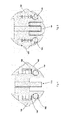
Fig. 1 is an exploded view of a lock system according to a preferred embodiment; -
Fig. 2 is a view of the lock core of the system ofFig. 1 ; -
Fig. 3 shows different notch positions on a sidebar blocking member and different configurations for an engagement portion; -
Fig. 4 is a cross-sectional view of the lock system ofFig. 1 having the sidebars blocked; -
Fig. 5 is a cross-sectional view of the lock system ofFig. 4 having the sidebars unblocked. -
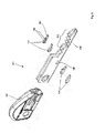
Fig. 6 is an exploded view of one embodiment of a key; -
Fig. 7 shows different configurations of possible cutout positions on a face plate. - The present invention will be discussed in the context of the BILOCK™ devices manufactured and sold by Australian Lock Company, a description of which can be found in
U.S. Patent No. 4,478,061 , the disclosure of which is herein incorporated by way of reference. It is emphasised, however, that in addition the present invention is readily applicable to single bladed key systems or any lock arrangement using a central core containing the complete set of lock coding elements, with suitable modifications to the recesses and sidebar arrangement as will be discussed below. - The present implementation, which will be described below, has been conceived as a direct improvement of the lock system disclosed in Australian Patent Application No.
2013248267 2014203184 2013248267 - Referring to
Figures 1 and2 , alock 110 has acore 112 received in alongitudinal cavity 116 of ahousing 118. As is well known, thecore 112 has akeyway 119 and a plurality ofguide bores 120 aligned with thekeyway 119 andreceptive locking pins 122. Aface plate 123 is located at the end face of thecore 112. Thelocking pins 122 are inwardly biased in the guide bores 120 bysprings 125 and acover plate 127 as per the original BILOCK™ design. On either side, thecore 112 features a longitudinally disposedsidebar recess 124 for the accommodation ofsidebars 126. Thesidebar recess 124 is in communication with the guide bores 120. Thesidebars 126 feature a series of inwardly extendingprotrusions 128 in the shape of pins and are biased away from theguide bores 120 bysidebar springs 129 or other biasing means as known in the art. At the end of thecore 112 opposite the key entry of thekeyway 119 the body of thecore 112 is flattened on either side to provide a suitable means for interacting with a latch mechanism (not shown). - As per the original BILOCK™ design, on the inner surface of the housing are two
longitudinal slots 130. Thelongitudinal slots 130 are shaped to receive thesidebars 126, which are biased theretowards. - Each
locking pin 122 is provided with ahole 136. Theholes 136 correspond to locking combinations for the lock dictated by the relative position of thehole 136 along the height of thelocking pin 122. - The combination of a
key 140 is provided bybitings 142 cut on thekey blade 144. When thekey blade 144 is inserted into thekeyway 119, thebitings 142 move the locking pins 122 a corresponding height along the respective guide bores 120. In accordance with the normal operation of BILOCK™, a correctly coded key moves thelocking pins 122 so that therespective holes 136 are aligned with thesidebar recess 124 and are capable of receiving the inwardly extendingprotrusions 128 of thesidebars 126 when thesidebars 126 are caused to move against their bias inwardly. - As will be appreciated, an incorrectly coded key blade would not align the
holes 136, which would prevent thesidebar 126 moving inwardly and retain thesidebar 126 in thelongitudinal slot 130, hence preventing rotation of thelock core 112. - In contrast to the original BILOCK™ design, the
core 112 includes achannel 150 which extends longitudinally alongside thekeyway 119 and adjacent therecess 124. Thechannel 150 has anopening 152 between thechannel 150 and theadjacent recess 124. Within thechannel 150 is slideably arranged asidebar blocking member 154 which is biased towards the end face of thecore 112 bysprings 156 or other biasing means as known in the art. - As shown in
Fig 3 , thesidebar blocking member 154 has anotch 158 which can be arranged on one of a number of positions along themember 154. - The
sidebar 126 includesadditional protrusions 160 on its upper and lower surface which are arranged and shaped to protrude through theopening 152 with theadjacent channel 150. Theseadditional protrusions 160 therefore extend into theadjacent channel 150 and are able to interact with thesidebar blocking member 154 as blockable portions of thesidebar 126. - When the
sidebar blocking member 154 is positioned so that itsnotch 158 is not aligned with theopening 152, thesidebar blocking member 154 acts as a barrier which prevents thesidebar 126 from moving inwardly due to the fact that theblockable portions 160 of thesidebar 126 would find their inward passage blocked by thesidebar blocking member 154, seeFig. 4 . - However, when the
sidebar blocking member 154 is positioned so that itsnotch 158 is aligned with theopening 152, thenotch 158 is shaped and sized so as to present an inward passage for theblockable portions 160 of thesidebar 126 and therefore allow inward movement of thesidebar 126, seeFig. 5 . - As will be appreciated, the
sidebar blocking member 154 and the modification to the sidebar act as an additional locking element to the lock. While a correctly coded BILOCK™ key would, when the blade is inserted into thekeyway 119, properly align theholes 136 of the locking pins 122, thesidebar 126 would be prevented from being able to engage theholes 136 of the locking pins 122 due to thenotch 158 of thesidebar blocking member 154 being unaligned with theopening 152. - The sidebar blocking member is formed with an
engageable portion 162 at one end. Theengagement portion 162 is selectably formed in one of a number of positions. In the embodiment shown inFig 3 , there are two possible positions, an upper position and a lower position, on each side of thekeyway 119. - The
face plate 123 includes a keyway cut out 164 which, when the face plate is in position at the end face of the core, aligns with thekeyway 119. In addition to thekeyway cutout 164 areadditional cutout portions 166. As shown, eachadditional cutout 166 can be selectively positioned at different heights with respect to thekeyway cutout 164. The different heights correspond with the different positions of theengageable portion 162 on thesidebar blocking member 154. As will be appreciated, properly selecting the engagement portion position to correspond to the height of the additional cutout exposes theengagement portion 162 via theadditional cutout 166. - In order to facilitate correct operation of the lock, not only do the
holes 136 of the locking pins 122 need to be aligned by correct coding on acorresponding key 140, but thesidebar blocking member 154 needs to be moved so that thenotch 158 is aligned with theopening 152. Movement of thesidebar blocking member 154 is achieved by modification to the original BILOCK™ key. - As shown in
Fig. 6 , the key 140 is formed of akey handle 146 and an attachablekey blade 144. The key 140 includes unblockingmembers 170 which operatively protrude from thekey handle 146 alongside the attachedkey blade 144. - The unblocking
member 170 includesprotrusions 186 which engageholes 188 formed on thekey blade 144 and are retained within thekey handle 146 when thekey handle 146 is attached. Aside from attaching the unblockingmember 170 to thekey blade 144, this arrangement also properly aligns the unblockingmember 170 with thekey blade 144. The unblockingmember 170 is formed with anelongated portion 190 which extends alongside thekey blade 144. As shown, theelongated portion 190 can be selectively formed at an upper or lower position. These different positions correlate to different heights, relative to the height of thekey blade 144, in which theelongated portion 190 can be arranged. - In operation, it is the
elongated portion 190 which enters theadditional cutout 166, during key blade insertion into thekey way 119, and engages theengageable portion 162 of thesidebar blocking member 154. As will be appreciated, for correct operation, the selected height position of theelongated portion 190 of the unblockingmember 170 needs to correlate with the selected height of thecutout portion 166 and the corresponding position of theengagement portion 162 of thesidebar blocking member 154 in order for engagement to occur. If the positions of theelongated portion 190 and theadditional cutout 166 do not correlate, then engagement will not occur during key blade insertion and, hence, thesidebar 126 will remain blocked. As a consequence, the selectable positions of both the elongated portion190 and theadditional cutout 166 offer extra coding for the lock system. - In addition, the length of the
elongated portion 190 is important for correct operation. The length of theelongated portion 190 dictates the amount that thesidebar blocking member 154 is moved in itschannel 150, assuming that the selected positions of theelongated portion 190 and theadditional cutout 166 correlate. For correct operation, the selected length of theelongated portion 190 needs to correlate with the selected notch position on thesidebar blocking member 154 so that thesidebar blocking member 154 is moved to the position in which thenotch 158 is aligned with theopening 152. As a consequence, the selectable length of theelongated portion 190 and the selectable notch position on thesidebar blocking member 154 adds further coding options for the lock system. - In effect, a correct key is required to have a number of correct factors in order to function. Firstly, it must have correctly coded
bitings 142 corresponding to the lock combination provided by the locking pins 122. Secondly, theelongated portion 190 position must correlate with the selected height of theadditional cutout 166 as well as the corresponding position of theengageable portion 162 of thesidebar blocking member 154 in order for theelongated portion 190 to engage and, therefore, move thesidebar blocking member 154. Lastly, the length of theelongated portion 190 must correlate with the notch position on thesidebar blocking member 154 in order for thenotch 158 to be moved to the unblocking position, in which it is aligned with theopening 152. In other words, the depth of penetration by the elongated portion dictates how far thesidebar blocking member 154 is moved. - In the embodiment illustrated, for each side of the key, there are effectively eight interchangeable variations on the unblocking
member 170 in order to provide for the two different heights of theelongated portion 190, as well as the four different lengths of the elongated portion 190 (to correspond to the four different notch positions shown inFig. 3 ). In an alternative embodiment, instead of having different variations on the unblockingmember 170, the requirements for providing different heights and depth of penetration of theelongated portion 190 could be facilitated by varying the position of theholes 188 on thekey blade 144 to achieve the same result. In this way a uniform version of the unblockingmember 170 could be utilised. The different height of its elongated portion could be dictated by forming theholes 188 at different heights on the key blade. Similarly, the different penetration depths, in order to move the notch158 the required distance, could be dictated by forming the holes at different positions along the length of the key. - In the embodiment illustrated, there is shown a BILOCK™ type of lock with two
sidebars 126. Eachsidebar 126 having only one respectivesidebar blocking member 154 in arespective channel 150. In this embodiment, the key only requires a corresponding number of unblockingmembers 170, that being two. However, as shown inFig 7 , this offers four variations on the positions of theadditional cutouts 166. - It will be appreciated that while the embodiment shown in
Fig. 3 show only two optional positions for theengageable portion 162, it may be possible to provide more than two options using precision engineering. In such a case, there would need to be a corresponding number of selectable heights for the associatedelongated portion 190 of the unblocking member as well as a corresponding number of heights for theadditional cutout 166. As a consequence, more than just the four variations shown inFig 7 could be derived. - It will be appreciated that in a single bladed key embodiment only a single set of locking
pins 122 would be required and, hence, use of only asingle sidebar 126. Consequently, a single sidebar arrangement may only require one respectivesidebar blocking member 154 and associatedchannel 150; whereby the key would only require a singlecorresponding unblocking member 170. - Conceivably, a variation on the embodiment illustrated could be the use of more than one sidebar blocking member for each sidebar. In which case, an additional channel would be required for the additional sidebar blocking member. Furthermore, an additional access would be required to allow engagement of the additional sidebar blocking member as well as an additional unblocking member appropriately positioned on the key for engaging the additional sidebar blocking member.
- In the assembled key of the illustrated embodiment, the
elongated portion 190 of the unblockingmember 170 is a fixed protrusion extending from the key handle. Conceivably, it would be possible to modify the design in order to allow the protrusions to be retractable within the key handle, such modifications have been proposed in Australian Patent Application No.2013204413 - Reference should be made to the various references incorporated herein in order to clarify any details of operation or construction, as the basic operation of the lock and key according to the implementation described as described in those references in more detail.
- It will be appreciated that variations and additions are possible within the general scope of the present invention. The embodiments described should be taken as illustrative of the implementation of the present invention, and not limitative thereof.
Claims (9)
- A lock system comprising:a lock, comprising:a lock housing having a cylindrical cavity for receiving a rotatable lock core, said housing having upon its internal surface a longitudinal slot;a substantially cylindrical lock core arranged within said cavity; said lock core having a keyway formed therein and extending longitudinally from an end face of said lock core; said lock core further including a plurality of guide bores which extend outwardly from said keyway and communicate therewith; each guide bore receiving a respective locking pin; wherein coding on a key blade operatively inserted into said keyway causes each locking pin to move along the respective guide bore; said lock core further including a recess extending outwardly from said plurality of guide bores and communicating therewith; said recess receiving a sidebar; said lock core further including a channel, said channel including an opening which communicates with said recess, and a sidebar blocking member slideably received in said channel;a face plate arranged to be positioned at the end face of said lock core, the face plate including a keyway cutout which aligns with said keyway, said face plate further including an additional cutout portion, wherein said additional cutout portion is located adjacent the keyway cutout and is selectably positioned at one of a plurality of heights relative to the height of the keyway cutout;each locking pin further comprising a hole, the position of the hole along the locking pin defining a locking combination for the respective locking pin;said sidebar further comprising protrusions which are directed inwardly towards said guide bores, said sidebar being biased outwardly away from said side bores and into said longitudinal slot; said sidebar further comprising a blockable portion which is arranged to protrude through said opening;said sidebar blocking member further comprising a notch; wherein said sidebar blocking member is biased towards a position in which said notch is not aligned with said opening, in which position said sidebar blocking member presents a barrier to said blockable portion and prevents said sidebar from moving inwardly towards said guide bores; said sidebar blocking member further includes an engagement portion which extends from an end of said sidebar blocking member and is formed at one of a plurality of selectable heights with respect to the end of said sidebar blocking member, each of said plurality of selectable heights of said engagement portion corresponding to a respective one of said plurality of heights of said additional cutout portion on said face plate, wherein the engagement portion is exposed to contact via said additional cutout portion when the selected heights of said engagement portion and said additional cutout portion correspond;said system further including:a key including a key handle and a key blade extending therefrom; said key blade having coded bitings, wherein upon insertion of said key blade into said keyway, correctly coded bitings move the locking pins along the guide bores until the holes are aligned with said recess; said key further including an unblocking member, which unblocking member operatively protrudes from said key handle substantially parallel to and adjacent a side of said key blade, wherein said unblocking member is selectively positioned at one of a plurality of heights relative to the height of said key blade, each of said plurality of heights corresponding respectively to one of said plurality of heights of said additional cutout portion on said face plate;wherein operatively, during key blade insertion into said key way, said unblocking member, being positioned at a selected height corresponding with the selected height of the additional cutout portion, engages said exposed engagement portion and moves said sidebar blocking member to an unblocking position in which said notch is aligned with said opening, in which unblocking position said sidebar blocking member presents no barrier to said blockable portion; wherein turning the inserted key causes the lock core to attempt to rotate, causing the unblocked sidebar to move inwardly against its bias and the inwardly directed protrusions enter the aligned holes, whereby the unblocked sidebar is capable of moving out of the longitudinal slot, thereby allowing the lock core to rotate.
- The lock system according to claim 1, wherein the position of the notch on the sidebar blocking member can be selected from a number of possible positions, the selected position dictating the required length which the corresponding unblocking member is required to operatively protrude from the key handle in order to align the selected notch position with the opening.
- The lock system of claim 1 or claim 2, wherein said lock core includes a second recess adapted to receive a second sidebar, said second sidebar being biased outwardly into a second longitudinal slot formed on the internal surface of said lock housing.
- The lock system of claim 3, wherein said lock core includes a second set of locking pins which operatively interact with said second sidebar.
- The lock system of claim 3 or claim 4, wherein said keyway is adapted to receive a key having a second blade, wherein said second blade operatively interacts with said second set of locking pins.
- The lock system of any one of claims 3 to 5, wherein said lock core includes at least one further longitudinal channel with an opening communicating with said second recess and an associated sidebar blocking member which interacts with said second sidebar; wherein said key includes at least one further unblocking member to operatively interact with a corresponding further sidebar blocking member.
- A lock including the features of the lock according to any one of claims 1 to 6, wherein said lock is able to interact with an appropriate key to form the lock system of any one of claims 1 to 6.
- A key including the features of the key set out in any one of claims 1 to 6, wherein said key is able to interact with an appropriate lock to form the lock system of any one of claims 1 to 6.
- A key handle adapted to receive a key blade in order to form the key of claim 8.
Applications Claiming Priority (2)
| Application Number | Priority Date | Filing Date | Title |
|---|---|---|---|
| AU2013248267A AU2013248267B1 (en) | 2013-10-28 | 2013-10-28 | Lock system |
| AU2014203184A AU2014203184B1 (en) | 2013-10-28 | 2014-06-12 | Lock system |
Publications (2)
| Publication Number | Publication Date |
|---|---|
| EP2899337A1 true EP2899337A1 (en) | 2015-07-29 |
| EP2899337B1 EP2899337B1 (en) | 2020-05-06 |
Family
ID=51221210
Family Applications (1)
| Application Number | Title | Priority Date | Filing Date |
|---|---|---|---|
| EP14189590.4A Active EP2899337B1 (en) | 2013-10-28 | 2014-10-20 | Lock system |
Country Status (5)
| Country | Link |
|---|---|
| US (1) | US9157256B2 (en) |
| EP (1) | EP2899337B1 (en) |
| AU (2) | AU2013248267B1 (en) |
| ES (1) | ES2806692T3 (en) |
| NZ (1) | NZ701142A (en) |
Families Citing this family (9)
| Publication number | Priority date | Publication date | Assignee | Title |
|---|---|---|---|---|
| BRPI1016250A2 (en) | 2009-06-30 | 2020-08-18 | United Video Properties, Inc | systems and methods for providing interactive media guidance on a wireless communication device |
| CA2926244C (en) * | 2013-10-03 | 2021-12-07 | Medeco Security Locks, Inc. | Cylinder lock with internal slider and key therefore |
| CA2938074A1 (en) | 2014-01-27 | 2015-07-30 | Assa Abloy High Security Group Inc. | Flat-bladed key and associated cylinder lock |
| CN107217921A (en) * | 2017-06-06 | 2017-09-29 | 广东镖臣防盗设备有限公司 | Anti-theft lock |
| CN108798264B (en) * | 2017-07-27 | 2023-11-10 | 谭召亮 | Key and automatic reset structure |
| US10995521B2 (en) * | 2018-06-27 | 2021-05-04 | Strattec Security Corporation | Linear lock |
| EP3969697B1 (en) * | 2019-05-17 | 2023-12-06 | Banham Patent Locks Holdings Limited | A lock configured to be operated by a key |
| US11624206B2 (en) * | 2019-10-03 | 2023-04-11 | Assa Abloy High Security Group Inc. | Lock cylinder and key with multiple, supplemental locking elements |
| US12077983B2 (en) | 2020-01-24 | 2024-09-03 | Assa Abloy High Security Group Inc. | Key and key blanks operable in vertically and horizontally oriented keyways |
Citations (4)
| Publication number | Priority date | Publication date | Assignee | Title |
|---|---|---|---|---|
| US4478061A (en) | 1981-03-30 | 1984-10-23 | Taboola Pty. Limited | Cylinder lock |
| WO2000014366A1 (en) * | 1998-09-04 | 2000-03-16 | Australian Lock Company Pty. Ltd. | Moveable element key and key handle and lock |
| US20020056301A1 (en) * | 1999-09-01 | 2002-05-16 | International Security Products, Inc. | High security side bar lock |
| US20120247163A1 (en) * | 2011-03-31 | 2012-10-04 | Gerry Damikolas | Rekeyable lock cylinder having rotatable key followers |
Family Cites Families (12)
| Publication number | Priority date | Publication date | Assignee | Title |
|---|---|---|---|---|
| US1899739A (en) * | 1929-02-26 | 1933-02-28 | Mehren Lock Co Inc | Key |
| US2423734A (en) * | 1944-05-10 | 1947-07-08 | Sterner Bernard | Key |
| US2690070A (en) * | 1951-05-26 | 1954-09-28 | Yale & Towne Mfg Co | Rotary tumbler cylinder lock |
| GB1227731A (en) * | 1966-10-14 | 1971-04-07 | ||
| US4446709A (en) * | 1981-07-14 | 1984-05-08 | Chicago Lock Co. | Cylinder lock mechanism |
| DE4420372A1 (en) * | 1994-06-10 | 1995-12-14 | Ymos Ag Ind Produkte | Locking system, in particular for motor vehicles and building equipment |
| AUPN890196A0 (en) * | 1996-03-25 | 1996-04-18 | Australian Lock Company Pty Ltd | Removable plug lock |
| US6945082B2 (en) * | 2001-02-06 | 2005-09-20 | Medeco Security Locks, Inc. | Key blank, key and master keying system |
| US6477875B2 (en) * | 2001-02-06 | 2002-11-12 | Medeco Security Locks, Inc. | Rotating pin tumbler side bar lock with side bar control |
| EP2173954B1 (en) * | 2007-03-14 | 2017-09-27 | Medeco Security Locks, Inc. | Hierarchical cylinder lock system |
| US8186194B2 (en) * | 2008-03-27 | 2012-05-29 | Medeco Security Locks, Inc. | Cylinder lock and auxiliary locking mechanism |
| AU2013204413A1 (en) | 2013-04-12 | 2014-10-30 | Camware Holdings Pty Ltd | Lock system |
-
2013
- 2013-10-28 AU AU2013248267A patent/AU2013248267B1/en active Active
-
2014
- 2014-06-12 AU AU2014203184A patent/AU2014203184B1/en active Active
- 2014-10-17 NZ NZ701142A patent/NZ701142A/en unknown
- 2014-10-20 EP EP14189590.4A patent/EP2899337B1/en active Active
- 2014-10-20 ES ES14189590T patent/ES2806692T3/en active Active
- 2014-10-27 US US14/524,707 patent/US9157256B2/en active Active
Patent Citations (4)
| Publication number | Priority date | Publication date | Assignee | Title |
|---|---|---|---|---|
| US4478061A (en) | 1981-03-30 | 1984-10-23 | Taboola Pty. Limited | Cylinder lock |
| WO2000014366A1 (en) * | 1998-09-04 | 2000-03-16 | Australian Lock Company Pty. Ltd. | Moveable element key and key handle and lock |
| US20020056301A1 (en) * | 1999-09-01 | 2002-05-16 | International Security Products, Inc. | High security side bar lock |
| US20120247163A1 (en) * | 2011-03-31 | 2012-10-04 | Gerry Damikolas | Rekeyable lock cylinder having rotatable key followers |
Also Published As
| Publication number | Publication date |
|---|---|
| ES2806692T3 (en) | 2021-02-18 |
| AU2013248267B1 (en) | 2014-06-26 |
| US20150114059A1 (en) | 2015-04-30 |
| US9157256B2 (en) | 2015-10-13 |
| AU2014203184B1 (en) | 2014-07-24 |
| EP2899337B1 (en) | 2020-05-06 |
| NZ701142A (en) | 2017-12-22 |
Similar Documents
| Publication | Publication Date | Title |
|---|---|---|
| US9157256B2 (en) | Lock system | |
| EP2126256B1 (en) | Cylinder lock and associated key and key blank therefor | |
| US9598880B2 (en) | Lock cylinder including modular plug | |
| US6718807B2 (en) | Lock device with removable core | |
| KR20130041318A (en) | Lock device | |
| EP3111025B1 (en) | Modular lock plug | |
| US10087655B2 (en) | Cylinder lock | |
| US10995521B2 (en) | Linear lock | |
| CN111133163B (en) | Locking device | |
| EP3103944B1 (en) | Key with a pivoting element and a lock | |
| AU2002225035B2 (en) | Cylinder lock with a cylinder housing and flange key for a cylinder lock | |
| AU2013204413A1 (en) | Lock system | |
| CN113445823B (en) | Lock core | |
| US10890012B2 (en) | Lock and key therefor | |
| US6854307B2 (en) | Lock-picking prevention apparatus | |
| RU2761228C2 (en) | Secret padlock | |
| US7793528B2 (en) | Key-operated mechanical lock | |
| EP2532811A1 (en) | Double-bit safety lock | |
| EP1366256B1 (en) | Rotating pin tumbler side bar lock with side bar control | |
| PL198808B1 (en) | Lock with a key | |
| JP3654848B2 (en) | Cylinder lock | |
| JP6268044B2 (en) | Wooden sliding door plug lock mounting structure | |
| AU2013204530B1 (en) | Lock Structure | |
| US20190071893A1 (en) | Cylinder Lock with Interact Mobile Devices | |
| RU2297930C1 (en) | Lock of antitheft device |
Legal Events
| Date | Code | Title | Description |
|---|---|---|---|
| PUAI | Public reference made under article 153(3) epc to a published international application that has entered the european phase |
Free format text: ORIGINAL CODE: 0009012 |
|
| 17P | Request for examination filed |
Effective date: 20141020 |
|
| AK | Designated contracting states |
Kind code of ref document: A1 Designated state(s): AL AT BE BG CH CY CZ DE DK EE ES FI FR GB GR HR HU IE IS IT LI LT LU LV MC MK MT NL NO PL PT RO RS SE SI SK SM TR |
|
| AX | Request for extension of the european patent |
Extension state: BA ME |
|
| 17P | Request for examination filed |
Effective date: 20160129 |
|
| RBV | Designated contracting states (corrected) |
Designated state(s): AL AT BE BG CH CY CZ DE DK EE ES FI FR GB GR HR HU IE IS IT LI LT LU LV MC MK MT NL NO PL PT RO RS SE SI SK SM TR |
|
| GRAP | Despatch of communication of intention to grant a patent |
Free format text: ORIGINAL CODE: EPIDOSNIGR1 |
|
| STAA | Information on the status of an ep patent application or granted ep patent |
Free format text: STATUS: GRANT OF PATENT IS INTENDED |
|
| INTG | Intention to grant announced |
Effective date: 20191205 |
|
| GRAS | Grant fee paid |
Free format text: ORIGINAL CODE: EPIDOSNIGR3 |
|
| GRAA | (expected) grant |
Free format text: ORIGINAL CODE: 0009210 |
|
| STAA | Information on the status of an ep patent application or granted ep patent |
Free format text: STATUS: THE PATENT HAS BEEN GRANTED |
|
| AK | Designated contracting states |
Kind code of ref document: B1 Designated state(s): AL AT BE BG CH CY CZ DE DK EE ES FI FR GB GR HR HU IE IS IT LI LT LU LV MC MK MT NL NO PL PT RO RS SE SI SK SM TR |
|
| REG | Reference to a national code |
Ref country code: GB Ref legal event code: FG4D |
|
| REG | Reference to a national code |
Ref country code: AT Ref legal event code: REF Ref document number: 1266967 Country of ref document: AT Kind code of ref document: T Effective date: 20200515 Ref country code: CH Ref legal event code: EP |
|
| REG | Reference to a national code |
Ref country code: IE Ref legal event code: FG4D |
|
| REG | Reference to a national code |
Ref country code: DE Ref legal event code: R096 Ref document number: 602014064857 Country of ref document: DE |
|
| REG | Reference to a national code |
Ref country code: FI Ref legal event code: FGE |
|
| REG | Reference to a national code |
Ref country code: NL Ref legal event code: FP |
|
| REG | Reference to a national code |
Ref country code: SE Ref legal event code: TRGR |
|
| REG | Reference to a national code |
Ref country code: LT Ref legal event code: MG4D |
|
| REG | Reference to a national code |
Ref country code: GR Ref legal event code: EP Ref document number: 20200402063 Country of ref document: GR Effective date: 20201014 |
|
| PG25 | Lapsed in a contracting state [announced via postgrant information from national office to epo] |
Ref country code: NO Free format text: LAPSE BECAUSE OF FAILURE TO SUBMIT A TRANSLATION OF THE DESCRIPTION OR TO PAY THE FEE WITHIN THE PRESCRIBED TIME-LIMIT Effective date: 20200806 Ref country code: PT Free format text: LAPSE BECAUSE OF FAILURE TO SUBMIT A TRANSLATION OF THE DESCRIPTION OR TO PAY THE FEE WITHIN THE PRESCRIBED TIME-LIMIT Effective date: 20200907 Ref country code: IS Free format text: LAPSE BECAUSE OF FAILURE TO SUBMIT A TRANSLATION OF THE DESCRIPTION OR TO PAY THE FEE WITHIN THE PRESCRIBED TIME-LIMIT Effective date: 20200906 Ref country code: LT Free format text: LAPSE BECAUSE OF FAILURE TO SUBMIT A TRANSLATION OF THE DESCRIPTION OR TO PAY THE FEE WITHIN THE PRESCRIBED TIME-LIMIT Effective date: 20200506 |
|
| PG25 | Lapsed in a contracting state [announced via postgrant information from national office to epo] |
Ref country code: HR Free format text: LAPSE BECAUSE OF FAILURE TO SUBMIT A TRANSLATION OF THE DESCRIPTION OR TO PAY THE FEE WITHIN THE PRESCRIBED TIME-LIMIT Effective date: 20200506 Ref country code: LV Free format text: LAPSE BECAUSE OF FAILURE TO SUBMIT A TRANSLATION OF THE DESCRIPTION OR TO PAY THE FEE WITHIN THE PRESCRIBED TIME-LIMIT Effective date: 20200506 Ref country code: RS Free format text: LAPSE BECAUSE OF FAILURE TO SUBMIT A TRANSLATION OF THE DESCRIPTION OR TO PAY THE FEE WITHIN THE PRESCRIBED TIME-LIMIT Effective date: 20200506 Ref country code: BG Free format text: LAPSE BECAUSE OF FAILURE TO SUBMIT A TRANSLATION OF THE DESCRIPTION OR TO PAY THE FEE WITHIN THE PRESCRIBED TIME-LIMIT Effective date: 20200806 |
|
| PG25 | Lapsed in a contracting state [announced via postgrant information from national office to epo] |
Ref country code: AL Free format text: LAPSE BECAUSE OF FAILURE TO SUBMIT A TRANSLATION OF THE DESCRIPTION OR TO PAY THE FEE WITHIN THE PRESCRIBED TIME-LIMIT Effective date: 20200506 |
|
| PG25 | Lapsed in a contracting state [announced via postgrant information from national office to epo] |
Ref country code: CZ Free format text: LAPSE BECAUSE OF FAILURE TO SUBMIT A TRANSLATION OF THE DESCRIPTION OR TO PAY THE FEE WITHIN THE PRESCRIBED TIME-LIMIT Effective date: 20200506 Ref country code: RO Free format text: LAPSE BECAUSE OF FAILURE TO SUBMIT A TRANSLATION OF THE DESCRIPTION OR TO PAY THE FEE WITHIN THE PRESCRIBED TIME-LIMIT Effective date: 20200506 Ref country code: DK Free format text: LAPSE BECAUSE OF FAILURE TO SUBMIT A TRANSLATION OF THE DESCRIPTION OR TO PAY THE FEE WITHIN THE PRESCRIBED TIME-LIMIT Effective date: 20200506 Ref country code: EE Free format text: LAPSE BECAUSE OF FAILURE TO SUBMIT A TRANSLATION OF THE DESCRIPTION OR TO PAY THE FEE WITHIN THE PRESCRIBED TIME-LIMIT Effective date: 20200506 Ref country code: SM Free format text: LAPSE BECAUSE OF FAILURE TO SUBMIT A TRANSLATION OF THE DESCRIPTION OR TO PAY THE FEE WITHIN THE PRESCRIBED TIME-LIMIT Effective date: 20200506 |
|
| REG | Reference to a national code |
Ref country code: DE Ref legal event code: R097 Ref document number: 602014064857 Country of ref document: DE |
|
| REG | Reference to a national code |
Ref country code: ES Ref legal event code: FG2A Ref document number: 2806692 Country of ref document: ES Kind code of ref document: T3 Effective date: 20210218 |
|
| PG25 | Lapsed in a contracting state [announced via postgrant information from national office to epo] |
Ref country code: SK Free format text: LAPSE BECAUSE OF FAILURE TO SUBMIT A TRANSLATION OF THE DESCRIPTION OR TO PAY THE FEE WITHIN THE PRESCRIBED TIME-LIMIT Effective date: 20200506 Ref country code: PL Free format text: LAPSE BECAUSE OF FAILURE TO SUBMIT A TRANSLATION OF THE DESCRIPTION OR TO PAY THE FEE WITHIN THE PRESCRIBED TIME-LIMIT Effective date: 20200506 |
|
| PLBE | No opposition filed within time limit |
Free format text: ORIGINAL CODE: 0009261 |
|
| STAA | Information on the status of an ep patent application or granted ep patent |
Free format text: STATUS: NO OPPOSITION FILED WITHIN TIME LIMIT |
|
| 26N | No opposition filed |
Effective date: 20210209 |
|
| PG25 | Lapsed in a contracting state [announced via postgrant information from national office to epo] |
Ref country code: SI Free format text: LAPSE BECAUSE OF FAILURE TO SUBMIT A TRANSLATION OF THE DESCRIPTION OR TO PAY THE FEE WITHIN THE PRESCRIBED TIME-LIMIT Effective date: 20200506 |
|
| REG | Reference to a national code |
Ref country code: CH Ref legal event code: PL |
|
| PG25 | Lapsed in a contracting state [announced via postgrant information from national office to epo] |
Ref country code: MC Free format text: LAPSE BECAUSE OF FAILURE TO SUBMIT A TRANSLATION OF THE DESCRIPTION OR TO PAY THE FEE WITHIN THE PRESCRIBED TIME-LIMIT Effective date: 20200506 Ref country code: LU Free format text: LAPSE BECAUSE OF NON-PAYMENT OF DUE FEES Effective date: 20201020 |
|
| REG | Reference to a national code |
Ref country code: BE Ref legal event code: MM Effective date: 20201031 |
|
| PG25 | Lapsed in a contracting state [announced via postgrant information from national office to epo] |
Ref country code: LI Free format text: LAPSE BECAUSE OF NON-PAYMENT OF DUE FEES Effective date: 20201031 Ref country code: CH Free format text: LAPSE BECAUSE OF NON-PAYMENT OF DUE FEES Effective date: 20201031 Ref country code: BE Free format text: LAPSE BECAUSE OF NON-PAYMENT OF DUE FEES Effective date: 20201031 |
|
| REG | Reference to a national code |
Ref country code: AT Ref legal event code: UEP Ref document number: 1266967 Country of ref document: AT Kind code of ref document: T Effective date: 20200506 |
|
| PG25 | Lapsed in a contracting state [announced via postgrant information from national office to epo] |
Ref country code: TR Free format text: LAPSE BECAUSE OF FAILURE TO SUBMIT A TRANSLATION OF THE DESCRIPTION OR TO PAY THE FEE WITHIN THE PRESCRIBED TIME-LIMIT Effective date: 20200506 Ref country code: MT Free format text: LAPSE BECAUSE OF FAILURE TO SUBMIT A TRANSLATION OF THE DESCRIPTION OR TO PAY THE FEE WITHIN THE PRESCRIBED TIME-LIMIT Effective date: 20200506 Ref country code: CY Free format text: LAPSE BECAUSE OF FAILURE TO SUBMIT A TRANSLATION OF THE DESCRIPTION OR TO PAY THE FEE WITHIN THE PRESCRIBED TIME-LIMIT Effective date: 20200506 |
|
| PG25 | Lapsed in a contracting state [announced via postgrant information from national office to epo] |
Ref country code: MK Free format text: LAPSE BECAUSE OF FAILURE TO SUBMIT A TRANSLATION OF THE DESCRIPTION OR TO PAY THE FEE WITHIN THE PRESCRIBED TIME-LIMIT Effective date: 20200506 |
|
| PGFP | Annual fee paid to national office [announced via postgrant information from national office to epo] |
Ref country code: NL Payment date: 20231024 Year of fee payment: 10 |
|
| PGFP | Annual fee paid to national office [announced via postgrant information from national office to epo] |
Ref country code: GB Payment date: 20231019 Year of fee payment: 10 Ref country code: GR Payment date: 20231027 Year of fee payment: 10 |
|
| PGFP | Annual fee paid to national office [announced via postgrant information from national office to epo] |
Ref country code: ES Payment date: 20231123 Year of fee payment: 10 |
|
| PGFP | Annual fee paid to national office [announced via postgrant information from national office to epo] |
Ref country code: SE Payment date: 20231018 Year of fee payment: 10 Ref country code: IT Payment date: 20231018 Year of fee payment: 10 Ref country code: IE Payment date: 20231020 Year of fee payment: 10 Ref country code: FR Payment date: 20231019 Year of fee payment: 10 Ref country code: FI Payment date: 20231023 Year of fee payment: 10 Ref country code: DE Payment date: 20231024 Year of fee payment: 10 Ref country code: AT Payment date: 20231024 Year of fee payment: 10 |