EP2898980A2 - Verfahren zum Verbinden einer metallischen Komponente mit einer nichtmetallischen Komponente mithilfe eines kompatiblen Materials - Google Patents
Verfahren zum Verbinden einer metallischen Komponente mit einer nichtmetallischen Komponente mithilfe eines kompatiblen Materials Download PDFInfo
- Publication number
- EP2898980A2 EP2898980A2 EP15152362.8A EP15152362A EP2898980A2 EP 2898980 A2 EP2898980 A2 EP 2898980A2 EP 15152362 A EP15152362 A EP 15152362A EP 2898980 A2 EP2898980 A2 EP 2898980A2
- Authority
- EP
- European Patent Office
- Prior art keywords
- metallic component
- compliant material
- bonding
- temperature
- assembly
- Prior art date
- Legal status (The legal status is an assumption and is not a legal conclusion. Google has not performed a legal analysis and makes no representation as to the accuracy of the status listed.)
- Granted
Links
Images


Classifications
-
- C—CHEMISTRY; METALLURGY
- C04—CEMENTS; CONCRETE; ARTIFICIAL STONE; CERAMICS; REFRACTORIES
- C04B—LIME, MAGNESIA; SLAG; CEMENTS; COMPOSITIONS THEREOF, e.g. MORTARS, CONCRETE OR LIKE BUILDING MATERIALS; ARTIFICIAL STONE; CERAMICS; REFRACTORIES; TREATMENT OF NATURAL STONE
- C04B37/00—Joining burned ceramic articles with other burned ceramic articles or other articles by heating
- C04B37/02—Joining burned ceramic articles with other burned ceramic articles or other articles by heating with metallic articles
- C04B37/023—Joining burned ceramic articles with other burned ceramic articles or other articles by heating with metallic articles characterised by the interlayer used
- C04B37/026—Joining burned ceramic articles with other burned ceramic articles or other articles by heating with metallic articles characterised by the interlayer used consisting of metals or metal salts
-
- B—PERFORMING OPERATIONS; TRANSPORTING
- B23—MACHINE TOOLS; METAL-WORKING NOT OTHERWISE PROVIDED FOR
- B23K—SOLDERING OR UNSOLDERING; WELDING; CLADDING OR PLATING BY SOLDERING OR WELDING; CUTTING BY APPLYING HEAT LOCALLY, e.g. FLAME CUTTING; WORKING BY LASER BEAM
- B23K20/00—Non-electric welding by applying impact or other pressure, with or without the application of heat, e.g. cladding or plating
- B23K20/02—Non-electric welding by applying impact or other pressure, with or without the application of heat, e.g. cladding or plating by means of a press ; Diffusion bonding
-
- B—PERFORMING OPERATIONS; TRANSPORTING
- B23—MACHINE TOOLS; METAL-WORKING NOT OTHERWISE PROVIDED FOR
- B23K—SOLDERING OR UNSOLDERING; WELDING; CLADDING OR PLATING BY SOLDERING OR WELDING; CUTTING BY APPLYING HEAT LOCALLY, e.g. FLAME CUTTING; WORKING BY LASER BEAM
- B23K20/00—Non-electric welding by applying impact or other pressure, with or without the application of heat, e.g. cladding or plating
- B23K20/02—Non-electric welding by applying impact or other pressure, with or without the application of heat, e.g. cladding or plating by means of a press ; Diffusion bonding
- B23K20/021—Isostatic pressure welding
-
- B—PERFORMING OPERATIONS; TRANSPORTING
- B23—MACHINE TOOLS; METAL-WORKING NOT OTHERWISE PROVIDED FOR
- B23K—SOLDERING OR UNSOLDERING; WELDING; CLADDING OR PLATING BY SOLDERING OR WELDING; CUTTING BY APPLYING HEAT LOCALLY, e.g. FLAME CUTTING; WORKING BY LASER BEAM
- B23K20/00—Non-electric welding by applying impact or other pressure, with or without the application of heat, e.g. cladding or plating
- B23K20/04—Non-electric welding by applying impact or other pressure, with or without the application of heat, e.g. cladding or plating by means of a rolling mill
-
- B—PERFORMING OPERATIONS; TRANSPORTING
- B23—MACHINE TOOLS; METAL-WORKING NOT OTHERWISE PROVIDED FOR
- B23K—SOLDERING OR UNSOLDERING; WELDING; CLADDING OR PLATING BY SOLDERING OR WELDING; CUTTING BY APPLYING HEAT LOCALLY, e.g. FLAME CUTTING; WORKING BY LASER BEAM
- B23K20/00—Non-electric welding by applying impact or other pressure, with or without the application of heat, e.g. cladding or plating
- B23K20/16—Non-electric welding by applying impact or other pressure, with or without the application of heat, e.g. cladding or plating with interposition of special material to facilitate connection of the parts, e.g. material for absorbing or producing gas
-
- B—PERFORMING OPERATIONS; TRANSPORTING
- B23—MACHINE TOOLS; METAL-WORKING NOT OTHERWISE PROVIDED FOR
- B23K—SOLDERING OR UNSOLDERING; WELDING; CLADDING OR PLATING BY SOLDERING OR WELDING; CUTTING BY APPLYING HEAT LOCALLY, e.g. FLAME CUTTING; WORKING BY LASER BEAM
- B23K20/00—Non-electric welding by applying impact or other pressure, with or without the application of heat, e.g. cladding or plating
- B23K20/22—Non-electric welding by applying impact or other pressure, with or without the application of heat, e.g. cladding or plating taking account of the properties of the materials to be welded
- B23K20/233—Non-electric welding by applying impact or other pressure, with or without the application of heat, e.g. cladding or plating taking account of the properties of the materials to be welded without ferrous layer
- B23K20/2333—Non-electric welding by applying impact or other pressure, with or without the application of heat, e.g. cladding or plating taking account of the properties of the materials to be welded without ferrous layer one layer being aluminium, magnesium or beryllium
-
- B—PERFORMING OPERATIONS; TRANSPORTING
- B32—LAYERED PRODUCTS
- B32B—LAYERED PRODUCTS, i.e. PRODUCTS BUILT-UP OF STRATA OF FLAT OR NON-FLAT, e.g. CELLULAR OR HONEYCOMB, FORM
- B32B15/00—Layered products comprising a layer of metal
- B32B15/04—Layered products comprising a layer of metal comprising metal as the main or only constituent of a layer, which is next to another layer of the same or of a different material
-
- B—PERFORMING OPERATIONS; TRANSPORTING
- B32—LAYERED PRODUCTS
- B32B—LAYERED PRODUCTS, i.e. PRODUCTS BUILT-UP OF STRATA OF FLAT OR NON-FLAT, e.g. CELLULAR OR HONEYCOMB, FORM
- B32B7/00—Layered products characterised by the relation between layers; Layered products characterised by the relative orientation of features between layers, or by the relative values of a measurable parameter between layers, i.e. products comprising layers having different physical, chemical or physicochemical properties; Layered products characterised by the interconnection of layers
- B32B7/04—Interconnection of layers
-
- B—PERFORMING OPERATIONS; TRANSPORTING
- B23—MACHINE TOOLS; METAL-WORKING NOT OTHERWISE PROVIDED FOR
- B23K—SOLDERING OR UNSOLDERING; WELDING; CLADDING OR PLATING BY SOLDERING OR WELDING; CUTTING BY APPLYING HEAT LOCALLY, e.g. FLAME CUTTING; WORKING BY LASER BEAM
- B23K2103/00—Materials to be soldered, welded or cut
- B23K2103/16—Composite materials
-
- B—PERFORMING OPERATIONS; TRANSPORTING
- B32—LAYERED PRODUCTS
- B32B—LAYERED PRODUCTS, i.e. PRODUCTS BUILT-UP OF STRATA OF FLAT OR NON-FLAT, e.g. CELLULAR OR HONEYCOMB, FORM
- B32B2311/00—Metals, their alloys or their compounds
- B32B2311/24—Aluminium
-
- B—PERFORMING OPERATIONS; TRANSPORTING
- B32—LAYERED PRODUCTS
- B32B—LAYERED PRODUCTS, i.e. PRODUCTS BUILT-UP OF STRATA OF FLAT OR NON-FLAT, e.g. CELLULAR OR HONEYCOMB, FORM
- B32B2315/00—Other materials containing non-metallic inorganic compounds not provided for in groups B32B2311/00 - B32B2313/04
- B32B2315/02—Ceramics
-
- B—PERFORMING OPERATIONS; TRANSPORTING
- B32—LAYERED PRODUCTS
- B32B—LAYERED PRODUCTS, i.e. PRODUCTS BUILT-UP OF STRATA OF FLAT OR NON-FLAT, e.g. CELLULAR OR HONEYCOMB, FORM
- B32B2605/00—Vehicles
- B32B2605/18—Aircraft
-
- C—CHEMISTRY; METALLURGY
- C04—CEMENTS; CONCRETE; ARTIFICIAL STONE; CERAMICS; REFRACTORIES
- C04B—LIME, MAGNESIA; SLAG; CEMENTS; COMPOSITIONS THEREOF, e.g. MORTARS, CONCRETE OR LIKE BUILDING MATERIALS; ARTIFICIAL STONE; CERAMICS; REFRACTORIES; TREATMENT OF NATURAL STONE
- C04B2237/00—Aspects relating to ceramic laminates or to joining of ceramic articles with other articles by heating
- C04B2237/02—Aspects relating to interlayers, e.g. used to join ceramic articles with other articles by heating
- C04B2237/12—Metallic interlayers
- C04B2237/121—Metallic interlayers based on aluminium
-
- C—CHEMISTRY; METALLURGY
- C04—CEMENTS; CONCRETE; ARTIFICIAL STONE; CERAMICS; REFRACTORIES
- C04B—LIME, MAGNESIA; SLAG; CEMENTS; COMPOSITIONS THEREOF, e.g. MORTARS, CONCRETE OR LIKE BUILDING MATERIALS; ARTIFICIAL STONE; CERAMICS; REFRACTORIES; TREATMENT OF NATURAL STONE
- C04B2237/00—Aspects relating to ceramic laminates or to joining of ceramic articles with other articles by heating
- C04B2237/50—Processing aspects relating to ceramic laminates or to the joining of ceramic articles with other articles by heating
- C04B2237/60—Forming at the joining interface or in the joining layer specific reaction phases or zones, e.g. diffusion of reactive species from the interlayer to the substrate or from a substrate to the joining interface, carbide forming at the joining interface
Definitions
- the present disclosure generally relates to a means for attaching a metallic component to a non-metallic component. More specifically, this disclosure relates to a means for attaching a metallic component to a non-metallic component using a compliant material having thermal properties intermediate those of the metallic component to a non-metallic component.
- Ceramic matrix composites are non-metallic materials that typically comprise ceramic fibers embedded in a composite matrix. CMCs are lightweight and exhibit markedly enhanced thermal strengths. These properties have made them attractive materials for component fabrication in many industries, such as the aerospace, automotive, and military equipment industries, where lightweight thermally resistant structures are desired. For example, CMCs continue to be explored for use in gas turbine engine applications to reduce the overall weight of the engine and improve engine efficiency and fuel savings. However, the strength and performance characteristics of CMCs may be dependent upon the integrity of the interfacial bond between the CMC component and any metallic component to which it is mated.
- CMCs coefficient of thermal expansion
- wear due to the differing thermal characteristics of metallic and non-metallic materials such as CMCs, including for example the coefficient of thermal expansion (CTE), and the significant wear that can be caused by the relative motion of the two mating components, it is difficult to provide a robust method for attaching a metallic component to a non-metallic component.
- CTE coefficient of thermal expansion
- the metallic/non-metallic interface is not permanently affixed but rather experiences significant relative motion.
- interfacial bond strength between the non-metallic component and the metallic component may be compromised upon exposure to high temperatures such as those experienced during some high-temperature engine operations, potentially leading to structural break-down of the component and possible in-service failure.
- strategies are needed to improve the interfacial bond strength of the metallic and non-metallic components.
- TLP Transient liquid phase
- PTLP partial transient liquid phase
- the TLP bonding process generally involves placing one or more thin compliant interlayers of material between the materials to be bonded to form an assembly; heating the assembly to a first temperature to temporarily produce a "transient" liquid in the bonding region; and maintaining the assembly at a bonding temperature (which may be the same as the first temperature) until the liquid has isothermally solidified due to diffusion of the compliant material into the two components being joined. Holding the assembly at the bonding temperature creates a substantially homogeneous diffusion bond between the two materials. The resulting bond can be stronger than either of the two components alone.
- the interlayer(s) can be in many forms, including thin foil, powder, paste, vapor deposition, or electroplating. Pressure may be applied to the opposing materials, and various heat sources used, including radiation, conduction, and radio-frequency induction.
- TLP bonding is that the resulting bond between the compliant material and the metallic component typically has a melting temperature above the temperature used for TLP bonding so that the formed bond may operate at temperatures well above the bonding temperature. This feature may be advantageous, for example, when joining temperature-sensitive metals whose microstructures could be damaged by too much thermal energy input. TLP bonding is often used in high-temperature applications where welding, brazing, and diffusion brazing cannot be used.
- the interlayer material may be any metallic material.
- Partial transient liquid phase (PTLP) bonding is a variant of TLP typically used to join ceramics.
- the interlayer may comprise thin layers of low-melting point metals or alloys on each side of a thicker refractory metallic layer.
- advantages of PTLP bonding are the following: (1) The dual nature of the multi-layer interlayer combines some beneficial properties of brazing and diffusion bonding. (2) Lower bonding temperatures can minimize thermally induced stresses.
- PTLP bonding is often performed with elemental interlayers designed to eventually form a solid solution after isothermal solidification and subsequent homogenization steps.
- the resulting strength of the solid-solution bond may not be sufficient for certain applications, especially in the aerospace industry.
- the present disclosure is directed to providing a means for attaching a metallic component to a non-metallic component such as a CMC using a compliant material having thermal properties intermediate those of the metallic component and the non-metallic component.
- the present disclosure relates to a means for attaching a metallic component to a non-metallic component using a compliant material having thermal properties intermediate those of the metallic component to a non-metallic component.
- a method of bonding a metallic component to a non-metallic component is provided.
- the method may comprise the steps of:
- the compliant material may be applied by a process selected from the group consisting of foil layup, powder application, plating, chemical vapor deposition, physical vapor deposition, cold spraying, and plasma spraying.
- the heating step may be accomplished by a process selected from the group consisting of radiation, conduction, radio-frequency induction, resistance, laser, and infrared heating.
- the compliant material may diffuse into both the metallic component and into the non-metallic component.
- the compliant material may be precipitation hardened by holding the assembly at a hardening temperature lower than the first temperature for a specified period of time.
- One of the one or more thermal properties may be the coefficient of thermal expansion.
- the non-metallic component may be a ceramic matrix composite.
- the compliant material may consists essentially of a single thin homogenous interlayer.
- the interlayer may be a thin foil (such as aluminum foil), a powder or a paste.
- the method may comprise the additional step of homogenizing the compliant material that forms the bond by maintaining the assembly at a suitable second temperature.
- the second temperature may be higher, lower or the same as the first temperature.
- the metallic component may be a platform and the non-metallic component may be a vane or fin structure mountable to the platform.
- the disclosure describes a bonded assembly comprising a metallic component; a non-metallic component; and a compliant material located in a bonding region between the metallic component and the non-metallic component, the compliant material having one or more thermal properties intermediate those of the metallic component and the non-metallic component.
- the thermal property may be the coefficient of thermal expansion.
- the non-metallic component may be a ceramic matrix composite.
- the compliant material may consist essentially of a single thin homogenous interlayer.
- the interlayer may be a thin foil, a powder and a paste.
- the disclosure provides a method of joining a metallic component to a component made of ceramic matrix composite material, the method comprising the steps of:
- the present disclosure relates to a method for attaching a metallic component 12 to a non-metallic component 14 using a compliant material 16 having thermal properties intermediate those of the metallic component 12 and the non-metallic component 14.
- the resulting bonded assembly 10 has a robust mechanical attachment along the bonding region 13 of the metallic component.
- the method can accommodate CTE mismatches and wear-type problems common to many assemblies of dissimilar materials.
- the method provides a sufficient bonding surface to accommodate relative motion and provide a durable wear surface that does not excessively wear/gall/micro-weld itself together, and provide the necessary damping and motion for proper operation.
- Figure 1 is a schematic of a bonded assembly 10 according to the disclosure.
- the assembly 10 comprises a compliant material 16 interposed between a non-metallic component 14 and a metallic component 12.
- the metallic component 12 may be a structure made of metallic or composite materials.
- the metallic component 12 may be a component of a jet engine such as a platform for a vane or fin structure.
- the non-metallic component 14 may be made of ceramic, a ceramic matrix composite (CMC) or any non-metallic material suitable for aeronautical use.
- the non-metallic component 14 may be a component of a jet engine such as a vane or fin structure.
- the compliant material 16 may be non-metallic or metallic (such as aluminum). In the embodiment shown in Figure 1 the compliant material 16 is a single thin homogenous layer of material. The compliant material 16 may be in the form of a thin foil, powder, paste or other suitable form.
- the compliant material 16 should have one or more thermal properties, such as the coefficient of thermal expansion (CTE), intermediate those of the metallic component and the non-metallic component.
- CTE coefficient of thermal expansion
- the compliant material 16 may be capable of imparting the non-metallic component 14 with one or more properties favorable to its operation and use, such as hardness or enhanced thermal stability.
- Figure 2 is a schematic representation illustrating another assembly 100 for forming a compliant wear surface between a metallic material 12 and a non-metallic material 14 in accordance with the present disclosure.
- the complaint material 16 comprises multiple layers.
- the compliant material 16 may comprise a relatively thicker middle layer 30 interposed between a first outer layer 32 and a second outer layer 34.
- the middle layer 30 and the outer layers 32, 34 may be metal, metal alloys or any suitable materials.
- the compliant material 16 may comprise layers of thin foil, powder or paste or combinations thereof.
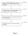
- Figure 3 is a flow-chart diagram illustrating steps involved in the creation of a bonded assembly 10 in accordance with a method of the present disclosure.
- the method may comprise the following steps:
- the bonding step may involve diffusion of the compliant material 16 into both the metallic component 12 and into the non-metallic component 14.
- the bonding step may involve precipitation hardening the compliant material 16 by holding the assembly 10 at a hardening temperature T PH lower than the bonding temperature T bond for a specified period of time, thereby creating a precipitation-hardened bond.
- the assembly 10 may be cooled below the hardening temperature T PH and then heated back up to the hardening temperature T PH , or simply cooled down from the bonding temperature T bond to the hardening temperature T PH and held there until the compliant material forming the bond is hardened.
- TLP or PTLP bonding may occur.
- at least one component of the compliant material 16 reacts with the non-metallic component 14 to wet it (adhere to it) while at least one component of the compliant material 16 diffuses into the metallic component 12. If the compliant material 16 is non-metallic, then the compliant material reacts with the metallic component rather than diffusing into the metallic component.
- the TLP or PTLP bonding materials can be accomplished using an alloy foil, multiple layers of elemental foils or any combination therefor. While foils may be suitable for this purpose, the compliant material 16 may also be a powder, powder compact, braze paste or applied via electroplating or physical vapor deposition (PVD). The selection of bonding materials can be used to further accommodate CTE or compliance mismatches.
- the method may include the additional step 106 of homogenizing the compliant material that forms the bond by maintaining the assembly at a suitable second temperature.
- the second temperature may be higher, lower or the same as the first temperature.
- the homogenizing step may involve diffusion of the middle layer 30 into the outer layers 32, 34.
- the present disclosure can find industrial applicability in many situations, including, but not limited to, industries requiring light-weight and high-strength hybrid components having improved strength and wear resistance, including components that operate in high-temperature environments, such as combustors in jet engines.
- the disclosure can facilitate the optimal selection of non-metallic materials independent of the optimal selection of the metallic materials.
- the technology as disclosed herein can provide CMC components mated to metallic components to increase the temperature resistance of the metallic component and improve the resistance of the compliant material against environmental effects such as erosion and foreign-object damage.
- CMCs may be mated with metallic or metallic composite components to provide hybrid composite structures.
- the technology as disclosed herein may find wide industrial applicability in a wide range of areas including, but not limited to, aerospace industries, automotive industries, and sporting industries.
Landscapes
- Engineering & Computer Science (AREA)
- Mechanical Engineering (AREA)
- Chemical & Material Sciences (AREA)
- Ceramic Engineering (AREA)
- Materials Engineering (AREA)
- Structural Engineering (AREA)
- Organic Chemistry (AREA)
- Laminated Bodies (AREA)
- Pressure Welding/Diffusion-Bonding (AREA)
Applications Claiming Priority (2)
| Application Number | Priority Date | Filing Date | Title |
|---|---|---|---|
| US201461931182P | 2014-01-24 | 2014-01-24 | |
| US14/601,520 US9969654B2 (en) | 2014-01-24 | 2015-01-21 | Method of bonding a metallic component to a non-metallic component using a compliant material |
Publications (3)
| Publication Number | Publication Date |
|---|---|
| EP2898980A2 true EP2898980A2 (de) | 2015-07-29 |
| EP2898980A3 EP2898980A3 (de) | 2015-08-19 |
| EP2898980B1 EP2898980B1 (de) | 2018-04-11 |
Family
ID=52391867
Family Applications (1)
| Application Number | Title | Priority Date | Filing Date |
|---|---|---|---|
| EP15152362.8A Revoked EP2898980B1 (de) | 2014-01-24 | 2015-01-23 | Verfahren zum Verbinden einer metallischen Komponente mit einer nichtmetallischen Komponente mithilfe eines kompatiblen Materials |
Country Status (2)
| Country | Link |
|---|---|
| US (2) | US9969654B2 (de) |
| EP (1) | EP2898980B1 (de) |
Families Citing this family (8)
| Publication number | Priority date | Publication date | Assignee | Title |
|---|---|---|---|---|
| US10472976B2 (en) * | 2015-06-05 | 2019-11-12 | Rolls-Royce Corporation | Machinable CMC insert |
| US10458653B2 (en) * | 2015-06-05 | 2019-10-29 | Rolls-Royce Corporation | Machinable CMC insert |
| US10465534B2 (en) | 2015-06-05 | 2019-11-05 | Rolls-Royce North American Technologies, Inc. | Machinable CMC insert |
| US11149646B2 (en) * | 2015-09-02 | 2021-10-19 | General Electric Company | Piston ring assembly for a turbine engine |
| US10661381B2 (en) * | 2017-02-24 | 2020-05-26 | Spirit Aerosystems, Inc. | Structure and method of making same involving welding otherwise non-weldable materials |
| US10702939B2 (en) * | 2018-04-05 | 2020-07-07 | Hamilton Sundstrand Corporation | Cold-spray braze material deposition |
| CN117206837A (zh) * | 2023-09-27 | 2023-12-12 | 南京理工大学 | 一种基于焊缝位置搅拌摩擦增材辅助的铝基复合材料焊接方法 |
| US12515110B1 (en) * | 2024-09-26 | 2026-01-06 | Topgolf Callaway Brands Corp. | Transient liquid phase bonding of golf club components |
Family Cites Families (56)
| Publication number | Priority date | Publication date | Assignee | Title |
|---|---|---|---|---|
| US3678570A (en) | 1971-04-01 | 1972-07-25 | United Aircraft Corp | Diffusion bonding utilizing transient liquid phase |
| GB1426873A (en) | 1972-05-03 | 1976-03-03 | Mullard Ltd | Methods of pressure bonding a ceramic member to another member |
| US4152816A (en) * | 1977-06-06 | 1979-05-08 | General Motors Corporation | Method of manufacturing a hybrid turbine rotor |
| JPS6036356B2 (ja) | 1981-07-13 | 1985-08-20 | 株式会社日立製作所 | 拡散接合法 |
| GB2136720B (en) | 1982-11-17 | 1985-12-18 | Ae Plc | Joining silicon nitride to metals |
| US4602731A (en) * | 1984-12-24 | 1986-07-29 | Borg-Warner Corporation | Direct liquid phase bonding of ceramics to metals |
| JPS61219765A (ja) * | 1985-03-22 | 1986-09-30 | 新明和工業株式会社 | セラミツクスと金属との複合体 |
| JPS6228091A (ja) * | 1985-07-26 | 1987-02-06 | Ishikawajima Harima Heavy Ind Co Ltd | セラミツクスの接合方法 |
| US4872606A (en) * | 1985-12-11 | 1989-10-10 | Hitachi, Ltd. | Sealed structure and production method thereof |
| FR2608674B1 (fr) | 1986-12-17 | 1991-04-19 | Snecma | Roue de turbine a aubes ceramique |
| JPS63220987A (ja) * | 1987-03-06 | 1988-09-14 | Natl Res Inst For Metals | アルミニウム及びアルミナセラミツクスの拡散接合法 |
| US5247986A (en) * | 1989-07-21 | 1993-09-28 | Lanxide Technology Company, Lp | Method of forming macrocomposite bodies by self-generated vacuum techniques, and products produced therefrom |
| US5139594A (en) * | 1990-06-26 | 1992-08-18 | The United States Of America As Represented By The United States Department Of Energy | Method for joining ceramic shapes |
| US5234152A (en) | 1992-01-07 | 1993-08-10 | Regents Of The University Of California | Transient liquid phase ceramic bonding |
| US5372298A (en) * | 1992-01-07 | 1994-12-13 | The Regents Of The University Of California | Transient liquid phase ceramic bonding |
| US5836075A (en) * | 1996-12-31 | 1998-11-17 | Westinghouse Electric Corporation | Process for forming combustion turbine components by transient liquid phase bonding |
| GB9709167D0 (en) * | 1997-05-06 | 1997-06-25 | Univ Cambridge Tech | Metal bonding |
| US6458466B1 (en) * | 1998-04-24 | 2002-10-01 | Dow Global Technologies Inc. | Brake or clutch components having a ceramic-metal composite friction material |
| US6173886B1 (en) | 1999-05-24 | 2001-01-16 | The University Of Tennessee Research Corportion | Method for joining dissimilar metals or alloys |
| US6619537B1 (en) * | 2000-06-12 | 2003-09-16 | Tosoh Smd, Inc. | Diffusion bonding of copper sputtering targets to backing plates using nickel alloy interlayers |
| CA2444664A1 (en) * | 2001-02-05 | 2002-08-15 | Rutgers, The State University | Transient eutectic phase process for ceramic-metal bonding, metallilzation, and compositing |
| JP2003101184A (ja) * | 2001-09-27 | 2003-04-04 | Kyocera Corp | セラミック回路基板およびその製造方法 |
| US6699571B1 (en) * | 2002-03-27 | 2004-03-02 | Morgan Advanced Ceramics, Inc. | Devices and methods for mounting components of electronic circuitry |
| JP3935037B2 (ja) * | 2002-09-30 | 2007-06-20 | Dowaホールディングス株式会社 | アルミニウム−セラミックス接合基板の製造方法 |
| FR2867096B1 (fr) * | 2004-03-08 | 2007-04-20 | Snecma Moteurs | Procede de fabrication d'un bord d'attaque ou de fuite de renforcement pour une aube de soufflante |
| US7565996B2 (en) | 2004-10-04 | 2009-07-28 | United Technologies Corp. | Transient liquid phase bonding using sandwich interlayers |
| DE102007020389B4 (de) | 2007-04-30 | 2014-01-09 | Airbus Operations Gmbh | Fügeverfahren zum Fügen von Bauteilen im Luft- und Raumfahrtbereich |
| US7857194B2 (en) * | 2007-05-01 | 2010-12-28 | University Of Dayton | Method of joining metals to ceramic matrix composites |
| US8087143B2 (en) * | 2007-06-20 | 2012-01-03 | Exothermics, Inc. | Method for producing armor through metallic encapsulation of a ceramic core |
| DE102007054071B4 (de) * | 2007-11-13 | 2010-06-10 | Eisfink Max Maier Gmbh & Co. Kg | Verbundmetallgegenstand und Verfahren zur Herstellung eines Verbundmetallgegenstands |
| JP4747315B2 (ja) * | 2007-11-19 | 2011-08-17 | 三菱マテリアル株式会社 | パワーモジュール用基板及びパワーモジュール |
| US9586382B2 (en) * | 2008-01-24 | 2017-03-07 | National Taiwan University | Ceramic/metal composite structure |
| US8609993B2 (en) * | 2008-05-16 | 2013-12-17 | Mitsubishi Materials Corporation | Power module substrate, power module, and method for manufacturing power module substrate |
| JP5848239B2 (ja) * | 2009-04-30 | 2016-01-27 | ツィンファ ユニバーシティ | セラミック表面の金属被覆方法及びセラミックとアルミニウムとの接合方法 |
| CN102576697B (zh) * | 2009-10-22 | 2014-11-12 | 三菱综合材料株式会社 | 功率模块用基板、带散热器的功率模块用基板、功率模块、功率模块用基板的制造方法及带散热器的功率模块用基板的制造方法 |
| WO2011052517A1 (ja) * | 2009-10-26 | 2011-05-05 | 株式会社Neomaxマテリアル | アルミニウム接合合金、その合金で形成された接合合金層を有するクラッド材及びアルミニウム接合複合材 |
| FR2957542B1 (fr) * | 2010-03-16 | 2012-05-11 | Commissariat Energie Atomique | Procede d'assemblage de pieces en materiaux a base de sic par brasage non-reactif, compositions de brasure, et joint et assemblage obtenus par ce procede. |
| US20120160084A1 (en) * | 2010-12-13 | 2012-06-28 | Benjamin Mosser | Ceramic armor and method of manufacturing by brazing ceramic to a metal frame |
| US8777583B2 (en) | 2010-12-27 | 2014-07-15 | General Electric Company | Turbine airfoil components containing ceramic-based materials and processes therefor |
| US8876481B2 (en) | 2011-01-05 | 2014-11-04 | General Electric Company | Turbine airfoil component assembly for use in a gas turbine engine and methods for fabricating same |
| JP5548167B2 (ja) * | 2011-07-11 | 2014-07-16 | 日本発條株式会社 | 積層体及び積層体の製造方法 |
| US8967974B2 (en) | 2012-01-03 | 2015-03-03 | General Electric Company | Composite airfoil assembly |
| US9789671B2 (en) * | 2012-02-28 | 2017-10-17 | Mino Ceramic Co., Ltd. | Shock absorbing member |
| WO2013130918A1 (en) * | 2012-02-29 | 2013-09-06 | Harris, Jonathan, H. | Transient liquid phase, pressureless joining of aluminum nitride components |
| JP5403129B2 (ja) * | 2012-03-30 | 2014-01-29 | 三菱マテリアル株式会社 | パワーモジュール用基板、ヒートシンク付パワーモジュール用基板、パワーモジュール、及びパワーモジュール用基板の製造方法 |
| JP2013229579A (ja) * | 2012-03-30 | 2013-11-07 | Mitsubishi Materials Corp | パワーモジュール用基板、ヒートシンク付パワーモジュール用基板及びパワーモジュール |
| FR2989607B1 (fr) * | 2012-04-19 | 2014-05-09 | Snecma | Procede de realisation d'un renfort metallique avec insert pour la protection d'un bord d'attaque en materiau composite |
| CA2904200A1 (en) * | 2013-03-05 | 2014-09-12 | Rolls-Royce Corporation | Dual-wall impingement, convection, effusion combustor tile |
| US9527777B2 (en) * | 2013-03-11 | 2016-12-27 | Rolls-Royce Corporation | Compliant layer for ceramic components and methods of forming the same |
| WO2014158598A1 (en) * | 2013-03-14 | 2014-10-02 | United Technologies Corporation | Transient liquid phase bonded turbine rotor assembly |
| CN105189109B (zh) * | 2013-03-14 | 2017-04-05 | 三菱综合材料株式会社 | 接合体、功率模块用基板及自带散热器的功率模块用基板 |
| WO2014149097A2 (en) * | 2013-03-15 | 2014-09-25 | United Technologies Corporation | Maxmet composites for turbine engine component tips |
| JP6111764B2 (ja) * | 2013-03-18 | 2017-04-12 | 三菱マテリアル株式会社 | パワーモジュール用基板の製造方法 |
| WO2015006435A1 (en) * | 2013-07-09 | 2015-01-15 | United Technologies Corporation | Hybrid plated composite stack |
| US9586868B2 (en) * | 2013-08-29 | 2017-03-07 | United Technologies Corporation | Method for joining dissimilar engine components |
| WO2015031106A1 (en) * | 2013-08-29 | 2015-03-05 | United Technologies Corporation | Cmc airfoil with monolithic ceramic core |
-
2015
- 2015-01-21 US US14/601,520 patent/US9969654B2/en active Active
- 2015-01-23 EP EP15152362.8A patent/EP2898980B1/de not_active Revoked
-
2018
- 2018-05-14 US US15/979,079 patent/US10752557B2/en active Active
Non-Patent Citations (1)
| Title |
|---|
| None |
Also Published As
| Publication number | Publication date |
|---|---|
| US10752557B2 (en) | 2020-08-25 |
| EP2898980A3 (de) | 2015-08-19 |
| US20170015596A1 (en) | 2017-01-19 |
| EP2898980B1 (de) | 2018-04-11 |
| US20180297900A1 (en) | 2018-10-18 |
| US9969654B2 (en) | 2018-05-15 |
Similar Documents
| Publication | Publication Date | Title |
|---|---|---|
| US10752557B2 (en) | Method of bonding a metallic component to a non-metallic component using a compliant material | |
| US10166751B2 (en) | Method for enhanced additive manufacturing | |
| JP5623025B2 (ja) | 過酷な環境の応用のための傾斜分布熱膨張係数を有する積み重ね複合構造 | |
| EP2111975B1 (de) | Verbundene verbundstrukturen mit einer abgestuften wärmeausdehnungskoeffizient für extremumgebungsanwendungen | |
| US10487670B2 (en) | Gas turbine engine component including a compliant layer | |
| US11969796B2 (en) | Tuned multilayered material systems and methods for manufacturing | |
| US20080274362A1 (en) | Method of joining metals to ceramic matrix composites | |
| EP3019300B1 (de) | Vorübergehende flüssigphasenbindung von metallbeschichteten materialien | |
| US11571742B2 (en) | Tuned multilayered material systems and methods for manufacturing | |
| CN1413792A (zh) | 钛铝基合金与钢的一种活性复合梯度阻隔扩散焊接方法 | |
| EP3003720B1 (de) | Ausscheidungsgehärtete teilweise flüchtige flüssig-phasenbindung | |
| US10071543B2 (en) | Precipitation hardened partial transient liquid phase bond | |
| CN104874909B (zh) | 石英复合陶瓷与铁镍合金的液相扩散连接方法 | |
| Li | Joining technology and application of advanced materials | |
| Elrefaey | High-temperature brazing in aerospace engineering | |
| US20160326892A1 (en) | Ceramic covered turbine components | |
| EP2179841B1 (de) | Funktionell gradierte Hochtemperaturverbindung von Fiberglasfasern mit Stahl | |
| Halbig et al. | Joining and integration of silicon carbide-based ceramic materials for aerospace applications: an overview | |
| Li et al. | Joining of Cf/SiC composite with Cu–Pd–V filler alloy and Mo interlayer | |
| Singh et al. | Advanced joining and integration technologies for ceramic matrix composite systems | |
| US10280769B2 (en) | Nonmetallic airfoil with a compliant attachment | |
| Sandin | What’s happening with aerospace brazing | |
| Halbig et al. | Development of High Temperature Joining and Thermomechanical Characterization Approaches for SiC/SiC Composites | |
| Coddington | Joining silicon carbide to metals using advanced vacuum brazing technology | |
| Singh et al. | Joining and Integration of Silicon Nitride Ceramics for Aerospace and Energy Systems |
Legal Events
| Date | Code | Title | Description |
|---|---|---|---|
| PUAL | Search report despatched |
Free format text: ORIGINAL CODE: 0009013 |
|
| PUAI | Public reference made under article 153(3) epc to a published international application that has entered the european phase |
Free format text: ORIGINAL CODE: 0009012 |
|
| 17P | Request for examination filed |
Effective date: 20150123 |
|
| AK | Designated contracting states |
Kind code of ref document: A2 Designated state(s): AL AT BE BG CH CY CZ DE DK EE ES FI FR GB GR HR HU IE IS IT LI LT LU LV MC MK MT NL NO PL PT RO RS SE SI SK SM TR |
|
| AX | Request for extension of the european patent |
Extension state: BA ME |
|
| AK | Designated contracting states |
Kind code of ref document: A3 Designated state(s): AL AT BE BG CH CY CZ DE DK EE ES FI FR GB GR HR HU IE IS IT LI LT LU LV MC MK MT NL NO PL PT RO RS SE SI SK SM TR |
|
| AX | Request for extension of the european patent |
Extension state: BA ME |
|
| RIC1 | Information provided on ipc code assigned before grant |
Ipc: B23K 20/16 20060101ALI20150710BHEP Ipc: B23K 20/02 20060101AFI20150710BHEP Ipc: B23K 20/233 20060101ALI20150710BHEP |
|
| 17P | Request for examination filed |
Effective date: 20160218 |
|
| RBV | Designated contracting states (corrected) |
Designated state(s): AL AT BE BG CH CY CZ DE DK EE ES FI FR GB GR HR HU IE IS IT LI LT LU LV MC MK MT NL NO PL PT RO RS SE SI SK SM TR |
|
| RAP1 | Party data changed (applicant data changed or rights of an application transferred) |
Owner name: UNITED TECHNOLOGIES CORPORATION |
|
| STAA | Information on the status of an ep patent application or granted ep patent |
Free format text: STATUS: EXAMINATION IS IN PROGRESS |
|
| 17Q | First examination report despatched |
Effective date: 20161124 |
|
| GRAP | Despatch of communication of intention to grant a patent |
Free format text: ORIGINAL CODE: EPIDOSNIGR1 |
|
| STAA | Information on the status of an ep patent application or granted ep patent |
Free format text: STATUS: GRANT OF PATENT IS INTENDED |
|
| INTG | Intention to grant announced |
Effective date: 20171018 |
|
| GRAS | Grant fee paid |
Free format text: ORIGINAL CODE: EPIDOSNIGR3 |
|
| GRAA | (expected) grant |
Free format text: ORIGINAL CODE: 0009210 |
|
| STAA | Information on the status of an ep patent application or granted ep patent |
Free format text: STATUS: THE PATENT HAS BEEN GRANTED |
|
| AK | Designated contracting states |
Kind code of ref document: B1 Designated state(s): AL AT BE BG CH CY CZ DE DK EE ES FI FR GB GR HR HU IE IS IT LI LT LU LV MC MK MT NL NO PL PT RO RS SE SI SK SM TR |
|
| REG | Reference to a national code |
Ref country code: GB Ref legal event code: FG4D |
|
| REG | Reference to a national code |
Ref country code: CH Ref legal event code: EP |
|
| REG | Reference to a national code |
Ref country code: AT Ref legal event code: REF Ref document number: 987473 Country of ref document: AT Kind code of ref document: T Effective date: 20180415 |
|
| REG | Reference to a national code |
Ref country code: IE Ref legal event code: FG4D |
|
| REG | Reference to a national code |
Ref country code: DE Ref legal event code: R096 Ref document number: 602015009706 Country of ref document: DE |
|
| REG | Reference to a national code |
Ref country code: NL Ref legal event code: MP Effective date: 20180411 |
|
| REG | Reference to a national code |
Ref country code: LT Ref legal event code: MG4D |
|
| PG25 | Lapsed in a contracting state [announced via postgrant information from national office to epo] |
Ref country code: NL Free format text: LAPSE BECAUSE OF FAILURE TO SUBMIT A TRANSLATION OF THE DESCRIPTION OR TO PAY THE FEE WITHIN THE PRESCRIBED TIME-LIMIT Effective date: 20180411 |
|
| PG25 | Lapsed in a contracting state [announced via postgrant information from national office to epo] |
Ref country code: LT Free format text: LAPSE BECAUSE OF FAILURE TO SUBMIT A TRANSLATION OF THE DESCRIPTION OR TO PAY THE FEE WITHIN THE PRESCRIBED TIME-LIMIT Effective date: 20180411 Ref country code: PL Free format text: LAPSE BECAUSE OF FAILURE TO SUBMIT A TRANSLATION OF THE DESCRIPTION OR TO PAY THE FEE WITHIN THE PRESCRIBED TIME-LIMIT Effective date: 20180411 Ref country code: ES Free format text: LAPSE BECAUSE OF FAILURE TO SUBMIT A TRANSLATION OF THE DESCRIPTION OR TO PAY THE FEE WITHIN THE PRESCRIBED TIME-LIMIT Effective date: 20180411 Ref country code: SE Free format text: LAPSE BECAUSE OF FAILURE TO SUBMIT A TRANSLATION OF THE DESCRIPTION OR TO PAY THE FEE WITHIN THE PRESCRIBED TIME-LIMIT Effective date: 20180411 Ref country code: BG Free format text: LAPSE BECAUSE OF FAILURE TO SUBMIT A TRANSLATION OF THE DESCRIPTION OR TO PAY THE FEE WITHIN THE PRESCRIBED TIME-LIMIT Effective date: 20180711 Ref country code: NO Free format text: LAPSE BECAUSE OF FAILURE TO SUBMIT A TRANSLATION OF THE DESCRIPTION OR TO PAY THE FEE WITHIN THE PRESCRIBED TIME-LIMIT Effective date: 20180711 Ref country code: AL Free format text: LAPSE BECAUSE OF FAILURE TO SUBMIT A TRANSLATION OF THE DESCRIPTION OR TO PAY THE FEE WITHIN THE PRESCRIBED TIME-LIMIT Effective date: 20180411 Ref country code: FI Free format text: LAPSE BECAUSE OF FAILURE TO SUBMIT A TRANSLATION OF THE DESCRIPTION OR TO PAY THE FEE WITHIN THE PRESCRIBED TIME-LIMIT Effective date: 20180411 |
|
| PG25 | Lapsed in a contracting state [announced via postgrant information from national office to epo] |
Ref country code: LV Free format text: LAPSE BECAUSE OF FAILURE TO SUBMIT A TRANSLATION OF THE DESCRIPTION OR TO PAY THE FEE WITHIN THE PRESCRIBED TIME-LIMIT Effective date: 20180411 Ref country code: RS Free format text: LAPSE BECAUSE OF FAILURE TO SUBMIT A TRANSLATION OF THE DESCRIPTION OR TO PAY THE FEE WITHIN THE PRESCRIBED TIME-LIMIT Effective date: 20180411 Ref country code: HR Free format text: LAPSE BECAUSE OF FAILURE TO SUBMIT A TRANSLATION OF THE DESCRIPTION OR TO PAY THE FEE WITHIN THE PRESCRIBED TIME-LIMIT Effective date: 20180411 Ref country code: GR Free format text: LAPSE BECAUSE OF FAILURE TO SUBMIT A TRANSLATION OF THE DESCRIPTION OR TO PAY THE FEE WITHIN THE PRESCRIBED TIME-LIMIT Effective date: 20180712 |
|
| REG | Reference to a national code |
Ref country code: AT Ref legal event code: MK05 Ref document number: 987473 Country of ref document: AT Kind code of ref document: T Effective date: 20180411 |
|
| PG25 | Lapsed in a contracting state [announced via postgrant information from national office to epo] |
Ref country code: PT Free format text: LAPSE BECAUSE OF FAILURE TO SUBMIT A TRANSLATION OF THE DESCRIPTION OR TO PAY THE FEE WITHIN THE PRESCRIBED TIME-LIMIT Effective date: 20180813 |
|
| REG | Reference to a national code |
Ref country code: DE Ref legal event code: R026 Ref document number: 602015009706 Country of ref document: DE |
|
| PLBI | Opposition filed |
Free format text: ORIGINAL CODE: 0009260 |
|
| PLAX | Notice of opposition and request to file observation + time limit sent |
Free format text: ORIGINAL CODE: EPIDOSNOBS2 |
|
| PG25 | Lapsed in a contracting state [announced via postgrant information from national office to epo] |
Ref country code: AT Free format text: LAPSE BECAUSE OF FAILURE TO SUBMIT A TRANSLATION OF THE DESCRIPTION OR TO PAY THE FEE WITHIN THE PRESCRIBED TIME-LIMIT Effective date: 20180411 Ref country code: DK Free format text: LAPSE BECAUSE OF FAILURE TO SUBMIT A TRANSLATION OF THE DESCRIPTION OR TO PAY THE FEE WITHIN THE PRESCRIBED TIME-LIMIT Effective date: 20180411 Ref country code: RO Free format text: LAPSE BECAUSE OF FAILURE TO SUBMIT A TRANSLATION OF THE DESCRIPTION OR TO PAY THE FEE WITHIN THE PRESCRIBED TIME-LIMIT Effective date: 20180411 Ref country code: SK Free format text: LAPSE BECAUSE OF FAILURE TO SUBMIT A TRANSLATION OF THE DESCRIPTION OR TO PAY THE FEE WITHIN THE PRESCRIBED TIME-LIMIT Effective date: 20180411 Ref country code: CZ Free format text: LAPSE BECAUSE OF FAILURE TO SUBMIT A TRANSLATION OF THE DESCRIPTION OR TO PAY THE FEE WITHIN THE PRESCRIBED TIME-LIMIT Effective date: 20180411 Ref country code: EE Free format text: LAPSE BECAUSE OF FAILURE TO SUBMIT A TRANSLATION OF THE DESCRIPTION OR TO PAY THE FEE WITHIN THE PRESCRIBED TIME-LIMIT Effective date: 20180411 |
|
| 26 | Opposition filed |
Opponent name: SAFRAN AIRCRAFT ENGINES Effective date: 20190110 |
|
| PG25 | Lapsed in a contracting state [announced via postgrant information from national office to epo] |
Ref country code: SM Free format text: LAPSE BECAUSE OF FAILURE TO SUBMIT A TRANSLATION OF THE DESCRIPTION OR TO PAY THE FEE WITHIN THE PRESCRIBED TIME-LIMIT Effective date: 20180411 Ref country code: IT Free format text: LAPSE BECAUSE OF FAILURE TO SUBMIT A TRANSLATION OF THE DESCRIPTION OR TO PAY THE FEE WITHIN THE PRESCRIBED TIME-LIMIT Effective date: 20180411 |
|
| PG25 | Lapsed in a contracting state [announced via postgrant information from national office to epo] |
Ref country code: SI Free format text: LAPSE BECAUSE OF FAILURE TO SUBMIT A TRANSLATION OF THE DESCRIPTION OR TO PAY THE FEE WITHIN THE PRESCRIBED TIME-LIMIT Effective date: 20180411 |
|
| PLBB | Reply of patent proprietor to notice(s) of opposition received |
Free format text: ORIGINAL CODE: EPIDOSNOBS3 |
|
| PG25 | Lapsed in a contracting state [announced via postgrant information from national office to epo] |
Ref country code: MC Free format text: LAPSE BECAUSE OF FAILURE TO SUBMIT A TRANSLATION OF THE DESCRIPTION OR TO PAY THE FEE WITHIN THE PRESCRIBED TIME-LIMIT Effective date: 20180411 |
|
| REG | Reference to a national code |
Ref country code: CH Ref legal event code: PL |
|
| PG25 | Lapsed in a contracting state [announced via postgrant information from national office to epo] |
Ref country code: LU Free format text: LAPSE BECAUSE OF NON-PAYMENT OF DUE FEES Effective date: 20190123 |
|
| REG | Reference to a national code |
Ref country code: BE Ref legal event code: MM Effective date: 20190131 |
|
| REG | Reference to a national code |
Ref country code: IE Ref legal event code: MM4A |
|
| PG25 | Lapsed in a contracting state [announced via postgrant information from national office to epo] |
Ref country code: BE Free format text: LAPSE BECAUSE OF NON-PAYMENT OF DUE FEES Effective date: 20190131 |
|
| PG25 | Lapsed in a contracting state [announced via postgrant information from national office to epo] |
Ref country code: LI Free format text: LAPSE BECAUSE OF NON-PAYMENT OF DUE FEES Effective date: 20190131 Ref country code: CH Free format text: LAPSE BECAUSE OF NON-PAYMENT OF DUE FEES Effective date: 20190131 |
|
| PG25 | Lapsed in a contracting state [announced via postgrant information from national office to epo] |
Ref country code: IE Free format text: LAPSE BECAUSE OF NON-PAYMENT OF DUE FEES Effective date: 20190123 |
|
| PG25 | Lapsed in a contracting state [announced via postgrant information from national office to epo] |
Ref country code: TR Free format text: LAPSE BECAUSE OF FAILURE TO SUBMIT A TRANSLATION OF THE DESCRIPTION OR TO PAY THE FEE WITHIN THE PRESCRIBED TIME-LIMIT Effective date: 20180411 |
|
| PG25 | Lapsed in a contracting state [announced via postgrant information from national office to epo] |
Ref country code: MT Free format text: LAPSE BECAUSE OF NON-PAYMENT OF DUE FEES Effective date: 20190123 |
|
| RAP2 | Party data changed (patent owner data changed or rights of a patent transferred) |
Owner name: RAYTHEON TECHNOLOGIES CORPORATION |
|
| PG25 | Lapsed in a contracting state [announced via postgrant information from national office to epo] |
Ref country code: CY Free format text: LAPSE BECAUSE OF FAILURE TO SUBMIT A TRANSLATION OF THE DESCRIPTION OR TO PAY THE FEE WITHIN THE PRESCRIBED TIME-LIMIT Effective date: 20180411 |
|
| PGFP | Annual fee paid to national office [announced via postgrant information from national office to epo] |
Ref country code: DE Payment date: 20201217 Year of fee payment: 7 |
|
| PG25 | Lapsed in a contracting state [announced via postgrant information from national office to epo] |
Ref country code: IS Free format text: LAPSE BECAUSE OF FAILURE TO SUBMIT A TRANSLATION OF THE DESCRIPTION OR TO PAY THE FEE WITHIN THE PRESCRIBED TIME-LIMIT Effective date: 20180811 |
|
| PG25 | Lapsed in a contracting state [announced via postgrant information from national office to epo] |
Ref country code: HU Free format text: LAPSE BECAUSE OF FAILURE TO SUBMIT A TRANSLATION OF THE DESCRIPTION OR TO PAY THE FEE WITHIN THE PRESCRIBED TIME-LIMIT; INVALID AB INITIO Effective date: 20150123 |
|
| RDAD | Information modified related to despatch of communication that patent is revoked |
Free format text: ORIGINAL CODE: EPIDOSCREV1 |
|
| RDAF | Communication despatched that patent is revoked |
Free format text: ORIGINAL CODE: EPIDOSNREV1 |
|
| REG | Reference to a national code |
Ref country code: DE Ref legal event code: R103 Ref document number: 602015009706 Country of ref document: DE Ref country code: DE Ref legal event code: R064 Ref document number: 602015009706 Country of ref document: DE |
|
| RDAG | Patent revoked |
Free format text: ORIGINAL CODE: 0009271 |
|
| STAA | Information on the status of an ep patent application or granted ep patent |
Free format text: STATUS: PATENT REVOKED |
|
| PGFP | Annual fee paid to national office [announced via postgrant information from national office to epo] |
Ref country code: GB Payment date: 20211216 Year of fee payment: 8 Ref country code: FR Payment date: 20211215 Year of fee payment: 8 |
|
| REG | Reference to a national code |
Ref country code: CH Ref legal event code: PL |
|
| REG | Reference to a national code |
Ref country code: FI Ref legal event code: MGE |
|
| 27W | Patent revoked |
Effective date: 20211023 |
|
| GBPR | Gb: patent revoked under art. 102 of the ep convention designating the uk as contracting state |
Effective date: 20211023 |
|
| PG25 | Lapsed in a contracting state [announced via postgrant information from national office to epo] |
Ref country code: MK Free format text: LAPSE BECAUSE OF FAILURE TO SUBMIT A TRANSLATION OF THE DESCRIPTION OR TO PAY THE FEE WITHIN THE PRESCRIBED TIME-LIMIT Effective date: 20180411 |