EP2898604B1 - Method and apparatus for transmitting and receiving channel state information in wireless communication system - Google Patents
Method and apparatus for transmitting and receiving channel state information in wireless communication system Download PDFInfo
- Publication number
- EP2898604B1 EP2898604B1 EP13838422.7A EP13838422A EP2898604B1 EP 2898604 B1 EP2898604 B1 EP 2898604B1 EP 13838422 A EP13838422 A EP 13838422A EP 2898604 B1 EP2898604 B1 EP 2898604B1
- Authority
- EP
- European Patent Office
- Prior art keywords
- csi
- channel state
- pmi
- state information
- cqi
- Prior art date
- Legal status (The legal status is an assumption and is not a legal conclusion. Google has not performed a legal analysis and makes no representation as to the accuracy of the status listed.)
- Active
Links
- 238000000034 method Methods 0.000 title claims description 61
- 238000004891 communication Methods 0.000 title description 8
- 239000011159 matrix material Substances 0.000 claims description 30
- 230000005540 biological transmission Effects 0.000 description 46
- 230000000875 corresponding effect Effects 0.000 description 29
- 238000010586 diagram Methods 0.000 description 28
- 230000007246 mechanism Effects 0.000 description 16
- 238000010295 mobile communication Methods 0.000 description 13
- 238000005259 measurement Methods 0.000 description 11
- 230000006870 function Effects 0.000 description 10
- 230000008569 process Effects 0.000 description 9
- 229920006934 PMI Polymers 0.000 description 5
- 238000004590 computer program Methods 0.000 description 4
- 238000012545 processing Methods 0.000 description 4
- 230000008054 signal transmission Effects 0.000 description 4
- 238000012986 modification Methods 0.000 description 3
- 230000004048 modification Effects 0.000 description 3
- 230000015556 catabolic process Effects 0.000 description 2
- 230000008859 change Effects 0.000 description 2
- 230000002596 correlated effect Effects 0.000 description 2
- 230000007423 decrease Effects 0.000 description 2
- 238000006731 degradation reaction Methods 0.000 description 2
- 238000005457 optimization Methods 0.000 description 2
- 230000009467 reduction Effects 0.000 description 2
- 230000011664 signaling Effects 0.000 description 2
- 101000741965 Homo sapiens Inactive tyrosine-protein kinase PRAG1 Proteins 0.000 description 1
- 102100038659 Inactive tyrosine-protein kinase PRAG1 Human genes 0.000 description 1
- 230000003044 adaptive effect Effects 0.000 description 1
- 238000013459 approach Methods 0.000 description 1
- 238000003491 array Methods 0.000 description 1
- 230000001413 cellular effect Effects 0.000 description 1
- 239000012141 concentrate Substances 0.000 description 1
- 238000010276 construction Methods 0.000 description 1
- 230000001276 controlling effect Effects 0.000 description 1
- 238000012937 correction Methods 0.000 description 1
- 238000013461 design Methods 0.000 description 1
- 230000000694 effects Effects 0.000 description 1
- 238000005516 engineering process Methods 0.000 description 1
- 230000007774 longterm Effects 0.000 description 1
- 238000004519 manufacturing process Methods 0.000 description 1
- 238000013507 mapping Methods 0.000 description 1
- 230000000116 mitigating effect Effects 0.000 description 1
- 238000013468 resource allocation Methods 0.000 description 1
- 238000003860 storage Methods 0.000 description 1
Images


Classifications
-
- H—ELECTRICITY
- H04—ELECTRIC COMMUNICATION TECHNIQUE
- H04B—TRANSMISSION
- H04B7/00—Radio transmission systems, i.e. using radiation field
- H04B7/02—Diversity systems; Multi-antenna system, i.e. transmission or reception using multiple antennas
- H04B7/04—Diversity systems; Multi-antenna system, i.e. transmission or reception using multiple antennas using two or more spaced independent antennas
- H04B7/0413—MIMO systems
- H04B7/0417—Feedback systems
-
- H—ELECTRICITY
- H04—ELECTRIC COMMUNICATION TECHNIQUE
- H04B—TRANSMISSION
- H04B7/00—Radio transmission systems, i.e. using radiation field
- H04B7/02—Diversity systems; Multi-antenna system, i.e. transmission or reception using multiple antennas
- H04B7/04—Diversity systems; Multi-antenna system, i.e. transmission or reception using multiple antennas using two or more spaced independent antennas
- H04B7/06—Diversity systems; Multi-antenna system, i.e. transmission or reception using multiple antennas using two or more spaced independent antennas at the transmitting station
- H04B7/0613—Diversity systems; Multi-antenna system, i.e. transmission or reception using multiple antennas using two or more spaced independent antennas at the transmitting station using simultaneous transmission
- H04B7/0615—Diversity systems; Multi-antenna system, i.e. transmission or reception using multiple antennas using two or more spaced independent antennas at the transmitting station using simultaneous transmission of weighted versions of same signal
- H04B7/0619—Diversity systems; Multi-antenna system, i.e. transmission or reception using multiple antennas using two or more spaced independent antennas at the transmitting station using simultaneous transmission of weighted versions of same signal using feedback from receiving side
- H04B7/0621—Feedback content
- H04B7/0626—Channel coefficients, e.g. channel state information [CSI]
-
- H—ELECTRICITY
- H04—ELECTRIC COMMUNICATION TECHNIQUE
- H04B—TRANSMISSION
- H04B7/00—Radio transmission systems, i.e. using radiation field
- H04B7/02—Diversity systems; Multi-antenna system, i.e. transmission or reception using multiple antennas
- H04B7/04—Diversity systems; Multi-antenna system, i.e. transmission or reception using multiple antennas using two or more spaced independent antennas
- H04B7/0404—Diversity systems; Multi-antenna system, i.e. transmission or reception using multiple antennas using two or more spaced independent antennas the mobile station comprising multiple antennas, e.g. to provide uplink diversity
-
- H—ELECTRICITY
- H04—ELECTRIC COMMUNICATION TECHNIQUE
- H04B—TRANSMISSION
- H04B7/00—Radio transmission systems, i.e. using radiation field
- H04B7/02—Diversity systems; Multi-antenna system, i.e. transmission or reception using multiple antennas
- H04B7/04—Diversity systems; Multi-antenna system, i.e. transmission or reception using multiple antennas using two or more spaced independent antennas
- H04B7/0413—MIMO systems
- H04B7/0456—Selection of precoding matrices or codebooks, e.g. using matrices antenna weighting
- H04B7/046—Selection of precoding matrices or codebooks, e.g. using matrices antenna weighting taking physical layer constraints into account
- H04B7/0469—Selection of precoding matrices or codebooks, e.g. using matrices antenna weighting taking physical layer constraints into account taking special antenna structures, e.g. cross polarized antennas into account
-
- H—ELECTRICITY
- H04—ELECTRIC COMMUNICATION TECHNIQUE
- H04B—TRANSMISSION
- H04B7/00—Radio transmission systems, i.e. using radiation field
- H04B7/02—Diversity systems; Multi-antenna system, i.e. transmission or reception using multiple antennas
- H04B7/04—Diversity systems; Multi-antenna system, i.e. transmission or reception using multiple antennas using two or more spaced independent antennas
- H04B7/0413—MIMO systems
- H04B7/0456—Selection of precoding matrices or codebooks, e.g. using matrices antenna weighting
- H04B7/0478—Special codebook structures directed to feedback optimisation
-
- H—ELECTRICITY
- H04—ELECTRIC COMMUNICATION TECHNIQUE
- H04B—TRANSMISSION
- H04B7/00—Radio transmission systems, i.e. using radiation field
- H04B7/02—Diversity systems; Multi-antenna system, i.e. transmission or reception using multiple antennas
- H04B7/04—Diversity systems; Multi-antenna system, i.e. transmission or reception using multiple antennas using two or more spaced independent antennas
- H04B7/06—Diversity systems; Multi-antenna system, i.e. transmission or reception using multiple antennas using two or more spaced independent antennas at the transmitting station
- H04B7/0613—Diversity systems; Multi-antenna system, i.e. transmission or reception using multiple antennas using two or more spaced independent antennas at the transmitting station using simultaneous transmission
- H04B7/0615—Diversity systems; Multi-antenna system, i.e. transmission or reception using multiple antennas using two or more spaced independent antennas at the transmitting station using simultaneous transmission of weighted versions of same signal
- H04B7/0619—Diversity systems; Multi-antenna system, i.e. transmission or reception using multiple antennas using two or more spaced independent antennas at the transmitting station using simultaneous transmission of weighted versions of same signal using feedback from receiving side
- H04B7/0636—Feedback format
- H04B7/0639—Using selective indices, e.g. of a codebook, e.g. pre-distortion matrix index [PMI] or for beam selection
-
- H—ELECTRICITY
- H04—ELECTRIC COMMUNICATION TECHNIQUE
- H04B—TRANSMISSION
- H04B7/00—Radio transmission systems, i.e. using radiation field
- H04B7/02—Diversity systems; Multi-antenna system, i.e. transmission or reception using multiple antennas
- H04B7/04—Diversity systems; Multi-antenna system, i.e. transmission or reception using multiple antennas using two or more spaced independent antennas
- H04B7/06—Diversity systems; Multi-antenna system, i.e. transmission or reception using multiple antennas using two or more spaced independent antennas at the transmitting station
- H04B7/0613—Diversity systems; Multi-antenna system, i.e. transmission or reception using multiple antennas using two or more spaced independent antennas at the transmitting station using simultaneous transmission
- H04B7/0615—Diversity systems; Multi-antenna system, i.e. transmission or reception using multiple antennas using two or more spaced independent antennas at the transmitting station using simultaneous transmission of weighted versions of same signal
- H04B7/0619—Diversity systems; Multi-antenna system, i.e. transmission or reception using multiple antennas using two or more spaced independent antennas at the transmitting station using simultaneous transmission of weighted versions of same signal using feedback from receiving side
- H04B7/0636—Feedback format
- H04B7/0645—Variable feedback
- H04B7/065—Variable contents, e.g. long-term or short-short
-
- H—ELECTRICITY
- H04—ELECTRIC COMMUNICATION TECHNIQUE
- H04L—TRANSMISSION OF DIGITAL INFORMATION, e.g. TELEGRAPHIC COMMUNICATION
- H04L25/00—Baseband systems
- H04L25/02—Details ; arrangements for supplying electrical power along data transmission lines
- H04L25/0202—Channel estimation
- H04L25/0224—Channel estimation using sounding signals
-
- H—ELECTRICITY
- H04—ELECTRIC COMMUNICATION TECHNIQUE
- H04L—TRANSMISSION OF DIGITAL INFORMATION, e.g. TELEGRAPHIC COMMUNICATION
- H04L5/00—Arrangements affording multiple use of the transmission path
- H04L5/003—Arrangements for allocating sub-channels of the transmission path
- H04L5/0048—Allocation of pilot signals, i.e. of signals known to the receiver
-
- H—ELECTRICITY
- H04—ELECTRIC COMMUNICATION TECHNIQUE
- H04B—TRANSMISSION
- H04B7/00—Radio transmission systems, i.e. using radiation field
- H04B7/02—Diversity systems; Multi-antenna system, i.e. transmission or reception using multiple antennas
- H04B7/04—Diversity systems; Multi-antenna system, i.e. transmission or reception using multiple antennas using two or more spaced independent antennas
- H04B7/06—Diversity systems; Multi-antenna system, i.e. transmission or reception using multiple antennas using two or more spaced independent antennas at the transmitting station
- H04B7/0613—Diversity systems; Multi-antenna system, i.e. transmission or reception using multiple antennas using two or more spaced independent antennas at the transmitting station using simultaneous transmission
- H04B7/0615—Diversity systems; Multi-antenna system, i.e. transmission or reception using multiple antennas using two or more spaced independent antennas at the transmitting station using simultaneous transmission of weighted versions of same signal
- H04B7/0619—Diversity systems; Multi-antenna system, i.e. transmission or reception using multiple antennas using two or more spaced independent antennas at the transmitting station using simultaneous transmission of weighted versions of same signal using feedback from receiving side
- H04B7/0621—Feedback content
- H04B7/063—Parameters other than those covered in groups H04B7/0623 - H04B7/0634, e.g. channel matrix rank or transmit mode selection
-
- H—ELECTRICITY
- H04—ELECTRIC COMMUNICATION TECHNIQUE
- H04B—TRANSMISSION
- H04B7/00—Radio transmission systems, i.e. using radiation field
- H04B7/02—Diversity systems; Multi-antenna system, i.e. transmission or reception using multiple antennas
- H04B7/04—Diversity systems; Multi-antenna system, i.e. transmission or reception using multiple antennas using two or more spaced independent antennas
- H04B7/06—Diversity systems; Multi-antenna system, i.e. transmission or reception using multiple antennas using two or more spaced independent antennas at the transmitting station
- H04B7/0613—Diversity systems; Multi-antenna system, i.e. transmission or reception using multiple antennas using two or more spaced independent antennas at the transmitting station using simultaneous transmission
- H04B7/0615—Diversity systems; Multi-antenna system, i.e. transmission or reception using multiple antennas using two or more spaced independent antennas at the transmitting station using simultaneous transmission of weighted versions of same signal
- H04B7/0619—Diversity systems; Multi-antenna system, i.e. transmission or reception using multiple antennas using two or more spaced independent antennas at the transmitting station using simultaneous transmission of weighted versions of same signal using feedback from receiving side
- H04B7/0621—Feedback content
- H04B7/0632—Channel quality parameters, e.g. channel quality indicator [CQI]
-
- H—ELECTRICITY
- H04—ELECTRIC COMMUNICATION TECHNIQUE
- H04L—TRANSMISSION OF DIGITAL INFORMATION, e.g. TELEGRAPHIC COMMUNICATION
- H04L5/00—Arrangements affording multiple use of the transmission path
- H04L5/003—Arrangements for allocating sub-channels of the transmission path
- H04L5/0053—Allocation of signaling, i.e. of overhead other than pilot signals
- H04L5/0057—Physical resource allocation for CQI
Definitions
- the present invention relates generally to a channel state information transmission/ reception method and apparatus and, more particularly, to a method and apparatus for transmitting and receiving channel state information in a wireless communication system supporting a plurality of antennas.
- a Reference Signal is used to measure the channel state (or quality) between a base station and users (such as, for example, signal strength and distortion, interference strength, and Gaussian noise), and is used in demodulation and decoding of a received data symbol in a wireless mobile communication system.
- the reference signal is also to measure a radio channel state.
- the receiver measures the strength of the reference signal transmitted by the transmitter at a predetermined transmit power to determine the radio channel state between the receiver and the transmitter.
- the receiver sends a request to the transmitter for a data rate based on the determined radio channel state.
- the 3 rd generation evolved mobile communication standards such as, for example, the 3 rd Generation Partnership Project Long Term Evolution-Advanced (3GPP LTE-A) and Institute of Electrical and Electronics Engineers (IEEE) 802.16m, adopt a multi-carrier multiple access technique such as Orthogonal Frequency Division Multiplexing (Multiple Access) (OFDM(A)).
- OFDM(A) Orthogonal Frequency Division Multiplexing
- the channel estimation and measurement performance is influenced by the number of symbols and the number of subcarriers to which the reference signal is mapped on the time-frequency resource grid.
- the channel estimation and measurement performance is also influenced by the power allocated for reference signal transmission. Accordingly, by allocating more radio resources (including time, frequency, and power), it is possible to improve channel estimation and measurement performance, resulting in improved received data symbol demodulation and decoding performance and channel state measurement accuracy.
- WO 2013/187669 A1 relates to a method and an apparatus for transmitting/receiving channel state information for use in a multi-antenna system.
- EP 2 665 203 A1 relates to a mobile station configured to receive transmissions from a two-dimensional array of antennas at the base station.
- WO2013/187669 and EP 2 665 203 are prior art according to Art. 54(3) EPC and are thus only relevant for novelty.
- an aspect of the present invention provides a method and apparatus for efficiently transmitting/receiving channel state information.
- Another aspect of the present invention provides a method and apparatus for efficiently transmitting/receiving the channel state information when using a plurality of antennas.
- a method for transmitting channel state information of a terminal is provided.
- a first Channel State Information Reference Signal (CSI-RS) and a second CSI-RS are received.
- Channel State Information (CSI) is generated based on both the first CSI-RS and the second CSI-RS.
- the CSI is transmitted.
- a terminal for transmitting channel state information includes a receiver that receives a first CSI-RS and a second CSI-RS.
- the terminal also includes a controller that generates CSI based on both the first CSI-RS and the second CSI-RS.
- the terminal further includes a transmitter that transmits the CSI.
- the channel state information feedback method of the present invention is capable of transmitting/receiving channel state information efficiently in a wireless system using a plurality of antennas.
- E-UTRA Evolved Universal Terrestrial Radio Access
- Embodiments of the present invention relate to a wireless mobile communication system and, in particular, to a method for efficiently transmitting/receiving channel state information in a wireless mobile communication system operating with a multicarrier multiple access scheme such as, for example, Orthogonal Frequency Division Multiple Access (OFDMA).
- OFDMA Orthogonal Frequency Division Multiple Access
- HSDPA High Speed Downlink Packet Access
- HSUPA High Speed Uplink Packet Access
- LTE Long Term Evolution
- LTE-A Long Term Evolution-to-term evolution
- 3GPP 3 rd Generation Partnership Project
- HRPD High Rate Packet Data
- 3GPP2 3 rd Generation Partnership Project-2
- 802.16 802.16 defined in IEEE
- Existing 3 rd generation mobile communications including LTE, Ultra Mobile Broadband (UMB), and 802.16m, operate based on a multi-carrier multiple access scheme and adopt Multiple Input Multiple Output (MIMO) with channel sensitive scheduling, such as beamforming and Adaptive Modulation and Coding (AMC), to improve transmission efficiency.
- MIMO Multiple Input Multiple Output
- AMC Adaptive Modulation and Coding
- These techniques increase the system throughput by improving transmission efficiency in such a way as to concentrate transmit power of a plurality of antennas, adjusting an amount of transmit data, and selectively transmitting data to the user with a best channel quality. Since most of these techniques operate based on the channel state information between the base station (eNB) and the terminal (UE or Mobile Station (MS)), the eNB or UE has to measure the channel state between the eNB and the UE.
- the signal used for channel state measurement is a Channel State Indication Reference Signal (CSI-RS).
- the eNB is a transmitter in downlink and a receiver in uplink.
- the one eNB may manage a plurality of cells for transmission/reception.
- a mobile communication system includes a plurality of eNBs distributed geographically, and each eNB performs transmission/reception through a plurality of cells.
- LTE/ LTE-A Existing 3 rd and 4 th Generation mobile communication systems represented by LTE/ LTE-A adopt a MIMO scheme with a plurality of transmit and receive antennas to transmit a plurality of information streams as spatially separated.
- This technique of transmitting the plurality of information streams as spatially separated is referred to as spatial multiplexing.
- the number of information streams capable of being spatially multiplexed depends on the number of antennas of the transmitter and the receiver.
- the number of information streams that can be spatially multiplexed is referred to rank in general.
- the spatial multiplexing of up to 8 x 8 antennas and up to rank 8 are supported.
- the FD-MIMO system to which a technique proposed in an embodiment of the present invention is applied, has been evolved from the LTE/LTE-A MIMO system supporting up to 8 transmit antennas so as to support 32 or more transmit antennas.
- the scope of the present invention is not limited thereto.
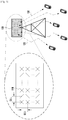
- FIG. 1 is a diagram illustrating an FD-MIMO system.
- the FD-MIMO system is a wireless communication system that is capable of transmitting data using a few dozen or more transmit antennas.
- a base station transmitter 100 transmits radio signals 120 and 130 through a few dozen or more transmit antennas.
- Transmit antennas 110 are arranged at a minimum distance among each other. The minimum distance may be half of the wavelength ( ⁇ /2) of the radio signal.
- the transmit antennas are arranged at the distance of half of the wavelength of the radio signal, the signals transmitted by the respective transmit antennas are influenced by the radio channel with low correlation. Assuming a radio signal band of 2GHz, this distance is 7.5 cm, and is shortened as the band becomes higher than 2GHz.
- a few dozen or more transmit antennas 110 arranged at the base station are used to transmit signals to one or more terminals as denoted by reference numerals 120 and 130.
- an appropriated precoding is applied.
- One terminal may receive a plurality of information streams.
- a number of information streams that a terminal can receive is determined depending on the number of receive antennas of the terminal, channel state, and reception capability of the terminal.
- the terminal In order to efficiently implement the FD-MIMO system, the terminal has to accurately measure the channel condition and interference size and efficiently transmit the channel state information to the base station. If the channel state information is received, the base station determines the terminals for downlink transmission, downlink data rate, and precoding to be applied. In the case of an FD-MIMO system using a large number of transmit antennas, if the channel state information transmission method of the legacy LTE/LTE-A system is applied without modification, the amount of control information to be transmitted in uplink significantly increases, resulting in uplink overhead.
- the mobile communication system is restricted in resources such as, for example, time, frequency, and transmission power. Accordingly, if a resource allocated for a reference signal increases, the resource amount to be allocated for data traffic channel transmission decreases, resulting in a reduction in the amount of data transmission. Although the channel estimation and measurement performance are improved, the data transmission amount decreases, resulting in reduction of entire system throughput. Thus, there is a need for efficiently allocating resources for reference signal and traffic channel transmissions in order to maximize the entire system throughput.
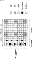
- FIG. 2 is a time-frequency grid illustrating a single RB of a downlink subframe as a smallest scheduling unit in the LTE/LTE-A system.
- the radio resource is of one subframe in the time domain and one RB in the frequency domain.
- the radio resource consists of 12 subcarriers in the frequency domain and 14 OFDM symbols in the time domain, i.e., 168 unique frequency-time positions.
- each frequency-time position is referred to as a Resource Element (RE).
- RE Resource Element
- the radio resource structured as shown in FIG. 2 can be used for transmitting different types of signals as follows.
- zero power CSI-RS can be configured in order for the UEs within the corresponding cells to receive the CSI-RSs transmitted by different eNBs in the LTE-A system.
- the zero power CSI-RS (muting) can be mapped to the positions designated for CSI-RS, and the UE receives the traffic signal skipping the corresponding radio resource in general.
- the zero power CSI-RS is referred to as muting.
- the zero power CSI-RS (muting) by nature is mapped to the CSI-RS position without transmission power allocation.
- the CSI-RS can be transmitted at some of the positions marked by A, B, C, D, E, F, G, H, I, and J, according to the number of number of antennas transmitting CSI-RS.
- the zero power CSI-RS (muting) can be mapped to some of the positions A, B, C, D, E, F, G, H, I, and J.
- the CSI-RS can be mapped to 2, 4, or 8 REs, according to the number of antenna ports for transmission. For two antenna ports, half of a specific pattern is used for CSI-RS transmission. For four antenna ports, an entire specific pattern is used for CSI-RS transmission. For eight antenna ports, two patterns are used for CSI-RS transmission. Muting is always performed by pattern. Specifically, although muting may be applied to a plurality of patterns, if the muting positions mismatch CSI-RS positions, it cannot be partially applied to one pattern.
- the CSI-RSs When transmitting CSI-RSs of two antenna ports, the CSI-RSs are mapped to two consecutive REs in the time domain and distinguished from each other using orthogonal codes. When transmitting CSI-RSs of four antenna ports, the CSI-RSs are mapped in the same way of mapping the two more CSI-RSs to two more consecutive REs. This is applied to the case of transmitting CSI-RSs of eight antenna ports.
- the reference signal has to be transmitted for downlink channel state measurement.
- the UE measures the channel state with the eNB using the CSI-RS transmitted by the eNB.
- the channel state is measured in consideration of a few factors including downlink interference.
- the downlink interference includes the interference caused by the antennas of neighbor eNBs and thermal noise that are important in determining the downlink channel condition. For example, when an eNB with one transmit antenna transmits a reference signal to a UE with one receive antenna, the UE has to determine an energy per symbol that can be received in downlink and an interference amount that may be received for the duration of receiving the corresponding symbol to calculate Es/Io from the received reference signal. The calculated Es/Io is reported to the eNB such that the eNB determines the downlink data rate for the UE.
- the UE feeds back the information on the downlink channel state for use in downlink scheduling of the eNB. Specifically, the UE measures the reference signal transmitted by the eNB in downlink and feeds back the information estimated from the reference signal to the eNB in the format defined in LTE/LTE-A standard.
- the UE feedback information includes the following three indicators:
- the RI, PMI, and CQI have associated meanings.
- the precoding matrix supported in LTE/LTE-A is configured differently per rank. Accordingly, the PMI value 'X' is interpreted differently for the cases of RI set to 1 and RI set to 2.
- the UE assumes that the PMI and RI, which it has reported, are applied by the eNB. Specifically, if the UE reports RI_X, PMI_Y, and CQI_Z; this means that the UE is capable of receiving the signal at the data rate corresponding to CQI_Z when the rank RI_X and the precoding matrix PMI_Y are applied. In this way, the UE calculates CQI with which the optimal performance is achieved in real transmission under the assumption of the transmission mode to be selected by the eNB.
- the number of CSI-RSs has to increase in proportion to the number of transmit antennas.
- the eNB has to transmit CSI-RSs of 8 ports to the UE for downlink channel state measurement.
- 8 REs In order to transmit 8-port CSI-RSs, 8 REs must be allocated for CSI-RS transmission in one RB.
- the REs indicated by A and B can be used for CSI-RS transmission of the corresponding eNB.
- the CSI-RS transmission resource increases in proportion to the number of transmit antennas.
- the eNB having 128 transmit antennas has to transmit CSI-RS on 128 REs in one RB.
- Such a CSI-RS transmission scheme consumes excessive radio resources, and thus, causes a shortage of resources for data transmission.
- an FD-MIMO may transmit CSI-RSs on N dimensions such that the UE performs channel measurements for a plurality of transmit antennas without excessive resource allocation for CSI-RS transmission.
- the CSI-RSs may be transmitted as separated into 2 dimensions.
- One CSI-RS is used as a horizontal CSI-RS for acquiring the horizontal direction channel information, while the other CSI-RS is used as a vertical CSI-RS for acquiring vertical direction channel information.
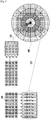
- FIG. 3 is a diagram illustrating a mechanism of CSI-RS transmission in FD-MIMO system, according to an embodiment of the present invention.
- the eNB operating in FD-MIMO mode has total 32 antennas.
- the number of antennas may vary depending on the embodiment.
- 32 antennas 300 are indicated by A0, ..., A3, B0, ..., B3, C0, ..., C3, D0, ..., D3, E0, ..., E3, F0, ..., F3, G0,..., G3, and H0, ..., H3.
- Two CSI-RSs are transmitted through the 32 antennas.
- the antenna ports corresponding to H-CSI-RS for use in measuring horizontal channel state consist of the following 8 antenna ports.
- the grouping a plurality of antennas into one CSI-RS port is a concept referred to as antenna virtualization.
- antenna virtualization is performed through linear combination of a plurality of antennas.
- the antenna ports corresponding to V-CSI-RS for use in measuring vertical channel state consist of the following 4 antenna ports.
- a plurality of antennas are arranged 2-dimensionally as described above.
- the antennas are arranged orthogonally forming M rows in the vertical direction and N columns in the horizontal direction.
- the UE is capable of measuring FD-MIMO channels using N H-CSI-RS ports and M V-CSI-RS ports.
- the channel state information can be acquired using M+N CSI-RS ports for M ⁇ N transmit antennas. Since the channel information on a large number of transmit antennas is acquired using a relatively small number of CSI-RS ports, it is advantageous in reducing the CSI-RS overhead.
- embodiments of the present invention are directed to channel information on the FD-MIMO transmit antennas using two CSI-RSs, this approach can be applied to the cases of using two or more CSI-RSs.
- the RSs of the 32 transmit antennas are mapped to 8 H-CSI-RS ports and 4 V-CSI-RS ports, and the UE measures the radio channels using the CSI-RSs of the FD-MIMO system.
- the H-CSI-RS can be used for estimating the horizontal angle between the UE and the eNB transmit antennas as denoted by reference numeral 310, while the V-CSI-RS can be used for estimating the vertical angle between the UE and the eNB transmit antennas as denoted by reference numeral 320.
- the following description is directed to the case of using the horizontal direction channel state information and the vertical direction channel state information.
- an eNB operates with two or more CSI-RSs
- other types of channel state information can also be applied to the horizontal and vertical direction channel state information.
- the UE is capable of acquiring the channel state information (first and second channel state information) based on the two respective CSI-RSs and the channel state information (third channel state information) based on both the CSI-RSs.
- the configuration described in the following description is applicable to various embodiments in similar manner.
- the following description is directed to an embodiment of the present invention using V-CSI-RS and H-CSI-RS.
- the channel state information corresponding to the vertical direction CSI-RS is referred to as vertical direction channel state information.
- the vertical direction channel state information includes at least one of RI, PMI, and CQI acquired based on the vertical direction CSI-RS.
- the channel state information corresponding to the horizontal direction CSI-RS is referred to as horizontal direction channel state information.
- the horizontal channel state information includes at least one of RI, PMI, and CQI acquired based on the horizontal direction CSI-RS.
- the UE When the eNB sends the UE two or more CSI-RSs, the UE is capable of transmitting the channel state information corresponding to the respective CSI-RSs.
- Each of the channel state information includes at least one of RI, PMI, and CQI.
- the UE may acquire the channel state information based on the two or more CSI-RSs in an embodiment of the present invention. Acquisition of the channel state information is described in greater detail below.
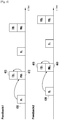
- FIG. 4 is a diagram illustrating a mechanism of transmitting RI, PMI, and CQI based on two CSI-RS in the feedback method, according to an embodiment of the present disclosure.
- the UE reports the radio channel state information of the FD-MIMO to the eNB by transmitting RI, PMI, and CQI for the respective CSI-RSs.
- the arrow indicates how a certain type of channel state information is related to other types of channel state information.
- the arrow starting from RIv 400 and ending at PMIv 410 indicates that the PMIv 410 is interpreted differently according to the value of RIv 400.
- the arrow means that the UE uses the value of the RI V 400 to interpret CQI V 420.
- the UE measures the V-CSI-RS and transmits the channel state information in the method indicated by "Feedback 1".
- the UE also measures the H-CSI-RS and transmits the channel state information in the method indicated by "Feedback 2".
- RI, PMI, and CQI are transmitted in the state of being correlated among each other.
- the RI V 400 notifies of the rank of the precoding matrix indicated by the PMI V 410.
- the CQI V 420 indicates the data rate at which the UE can receive data or a corresponding value in the case of applying the precoding matrix of the corresponding rank which is indicated by the PMI V 410, when the transmission is performed at the rank indicated by the RI V 400.
- the RI 430, the PMI 440, and CQI 450 are transmitted in the state of being correlated among each other like the case of "Feedback 1".
- one of the channel state information report methods may configure a plurality of feedback for a plurality of transmit antennas of the FD-MIMO eNB, and make the UE report channel state information to the eNB.
- This method is advantageous in that the UE is capable of generating and reporting channel state information for FD-MIMO without extra implementation.
- the channel state information report method of FIG. 4 it is difficult to achieve enough throughput of the FD-MIMO system. This is due to the fact that although the UE configures a plurality of feedback to report the channel state information to the eNB, the CQI is generated without an assumption on the precoding when the FD-MIMO is applied.
- both the vertical direction precoding matrix and the horizontal direction precoding matrix are applied to the signal transmitted by the UE.
- the UE receives the signal to which the precoding matrices corresponding to the PMI H 440 and the PMI V 410 other than the signal to which one of the PMI H 440 and the PMI V 410.
- the eNB has to determine the CQI to which both the vertical and horizontal direction precoding matrices are applied, without receipt of such a CQI. If the eNB determines the CQI to which both the vertical and horizontal direction precoding matrices are applied arbitrarily, this may cause degradation of system performance.
- one of the methods for mitigating the use of radio resource for CSI-RS transmission in the FD-MIMO system is to make the UE measure a plurality CSI-RSs capable of efficiently estimating a plurality of transmit antennas.
- Each CSI-RS can be used for the UE to measure the channel state of one of a plurality dimensions for measuring one radio channel.
- This method requires a relatively small amount of radio resources for CSI-RS transmission as compared to the method of allocating a unique CSI-RS ports for the respective transmit antennas.
- the UE is capable of efficiently measuring the channel state.
- Embodiments of the present invention propose a novel technology and apparatus that is capable of allowing the UE to measure a plurality of CSI-RSs and efficiently report the channel state information in the FD-MIMO system including a plurality of transmit antennas.
- FIG. 5 is a diagram illustrating a mechanism of transmitting channel state information, according to an embodiment of the present disclosure.
- the channel state information corresponding to the two CSI-RSs are reported as in the embodiment of FIG. 4 .
- the channel state information transmission method is indicated by "Feedback 1" as in the embodiment of FIG. 4 .
- the UE measures V-CSI-RS to report RI V 500, PMI V 510, and CQI V 520 to the eNB.
- the embodiment of FIG. 5 differs from the embodiment of FIG. 4 in the procedure of indication with "Feedback 2".
- the UE reports the CQI for the case where the precoding is applied in both the vertical and horizontal directions, i.e., CQI HV 550, to the eNB.
- the UE reports to the eNB the most recent PMI V 510 generated in the procedure indicated with "Feedback 1" and CQI HV 550 generated in the case where the precodings indicated by PMI 540, which is determined optimal based on the H-CSI-RS measurement.
- the UE measures the V-CSI-RS to generate the RI V 500, which is reported to the eNB.
- the UE determines the PMI V 510 optimal to the corresponding rank 500 and reports the CQI V 520 when the precoding indicated by the PMI V 510 is applied.
- the UE measures H-CSI-RS to generate RI 530, which is reported to the eNB.
- the UE reports to the eNB the CQI HV 550 generated by applying the precoding indicated by PMI 540 optimal to the corresponding rank 530 and the precoding indicated by the previously transmitted PMI V 510.
- the UE in order for the UE to report the CQI value for the case where the precoding matrix indicated by the PMI H 540 and the precoding matrix indicated by the PMI V 510 are allocated simultaneously to the eNB, the following may be required.
- the eNB notifies the UE of the correlation of the feedback information in configuring a plurality of feedbacks to the UE, and the UE generates CQI based thereon.
- a control message instructing to calculate the second CQI, i.e., the CQI HV 550, by applying the first PMI, i.e. the PMI V 510, and the second PMI, i.e. the PMI H 540, together has to be transmitted from the eNB to the UE.
- the UE calculates CQI under the assumption that the precoding indicated by RI and PMI it has reported is applied in downlink.
- the UE calculates CQI under the assumption that two precodings are simultaneously applied in downlink.
- the UE may interpret the application of two precodings as the Kronecker product.
- the Kronecker product is defined with two matrices as shown in Equation (1) below.
- a ⁇ B a 11 B ⁇ a 1 ⁇ n B ⁇ ⁇ ⁇ a m 1 B ⁇ a mn B
- a and B denote matrices
- a 11 to a mn denote elements of matrix A
- a ij denotes the element at i th row and j th column.
- the UE is capable of acquiring the precoding matrix for the case where two precoding matrices are applied simultaneously by replacing A and B with the precoding matrices indicated by the PMI H 540 and the PMI V 510.
- the UE calculates the CQI HV 550 under the assumption that the precoding matrix acquired by applying the Equation (1) to the precoding matrices indicated by the PMI H 540 and PMI V 510 is applied in downlink.
- the eNB configures one of the RI V 500 and the RI H 530 with rank 1 always. For example, if the CQI HV 550 is reported along with the RI H 530 to the eNB, the RI V 500 is restricted to be always set to 1.
- the rank supported in the case where two precoding matrices are applied simultaneously is determined depending on the RI H 530. Specifically, when the RI H 530 is set to 1, the UE is capable of supporting rank 1; and when the RI H 530 is set to 2, the UE is capable of supporting rank 2.
- the UE and the eNB operate in the FD-MIMO system under this assumption. Although two CSI-RSs are assumed in this embodiment of the present invention, if the number of CSI-RS is 3 or more, RIs have to be set to 1 with the exception of the RI corresponding to one CSI-RS.
- rank HV rank RI H ⁇ rank RI V
- the UE and the eNB exchange the channel state information under the assumption that the rank for the case where the vertical and horizontal direction precoding matrices are applied simultaneously is the product of the two ranks supportable in the respective directions. For example, if the UE reports the RI H set to 2 and RI V set to 3 to the eNB, the eNB and the UE assume that the rank for the case where all of the precoding matrices are applied is 6.
- LTE/LTE-A if the UE reports to the eNB the RI corresponding to rank 2 or higher, two CQI values are reported to the eNB. This is due to the fact that the eNB transmits two codewords to the UE, and thus, the UE has to separately report the CQIs corresponding to respective codewords.
- the UE transmits the two CQIs in the form of the CQI HV 550. Also, if the rank for the case where all of the precodings obtained by Equation (2) is 2 or higher, the eNB receives the two CQIs under the assumption that they are transmitted in the form of the CQI HV 550.
- transmission of "Feedback 1" and "Feedback 2" may cause collision.
- the term 'collision' refers to a situation in which transmission of "Feedback 1" and "Feedback 2" is required at the same time. If any collision is predicted, the UE may report the channel state information of one of "Feedback 1" and "Feedback 2".
- the FD-MIMO operation with the configuration of a plurality of feedback, as shown in FIG. 4 or 5 may cause the channel state information to be partially missed.
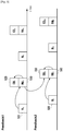
- FIG. 6 is a diagram illustrating a mechanism of transmitting channel state information, according to an embodiment of the present invention.
- the feedback method of FIG. 6 differs from that of FIG. 4 in that the feedback is completed in only one feedback process.
- the UE transmits RI HV 600 to report the horizontal and vertical direction ranks.
- Table 1 shows horizontal and vertical direction ranks (first second ranks).
- the eNB may acquire the horizontal and vertical direction ranks from the RI HV 600 transmitted by the UE.
- the UE determines the value of the RI HV 600 based on both the two CSI-RS, i.e., H-CSI-RS and V-CSI-RS.
- the eNB checks the information on the horizontal and vertical direction precodings and UE-supportable data rate based on PMIs 610 and 630 and CQIs 620 and 640 corresponding to the H-CSI-RS and V-CSI-RS. Since the horizontal and vertical direction PMIs and CQIs are transmitted alternately in one feedback process, it is possible to avoid the collisions of the feedback transmissions that may occur in the embodiments of FIGS. 4 and 5 . In FIG.
- the horizontal and vertical direction ranks may have different values depending on the value of the RI HV 600 reported by the UE.
- the precoding matrix indicated by the PMI H 610 is determined depending on the horizontal direction PMI indicated by the value of the RI HV 600.
- the UE also transmits CQI obtained under the assumption of the case where the precoding matrix indicated by the RI H 610 is applied, i.e., the CQI H 620.
- the UE measures the H-CSI-RS.
- the precoding matrix indicated by the PMI V 630 is determined depending on the vertical direction rank indicated by the RI HV 600.
- the UE also transmits CQI obtained under the assumption of the case where the precoding matrix indicated by the PMI V 630 is applied, i.e., the CQI V 640.
- the UE measures V-CSI-RS.
- the UE alternately transmits the horizontal channel state information 610 and 620 and the vertical channel state information 630 and 640. It is also possible to alternately transmit the horizontal and vertical channel state information in the same interval.
- the UE may report specific direction channel state information at an interval shorter than that of the other direction channel state information in view of system throughput optimization.
- the eNB may perform configuration thereon. Specifically, in the case that the UE reports different direction channel state information to the eNB in one feedback process, the eNB may notify the UE of the following information for configuration thereon.
- the subframe offset value is the value determining the subframe position for real transmission in a period. For example, if the period is 10 milliseconds (msec) and the subframe offset is 5, this means that the corresponding signal is transmitted at the subframe 5 in the period of 10 milliseconds.
- the horizontal and vertical direction ranks reported from the UE to the eNB may be determined depending on different rank restrictions.
- the rank restriction is to restrict, when the UE measures the RS to determine the rank, the maximum value to the value preconfigured by the eNB.
- the eNB may notify the UE of the following information through higher layer signaling or in another method.
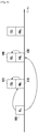
- FIG. 7 is a diagram illustrating a mechanism of transmitting channel state information, according to another embodiment of the present invention.
- the UE reports the channel state information to the eNB in one feedback process as in the embodiment of FIG. 6 .
- the embodiment of FIG. 7 differs from the embodiment of FIG. 6 in that the horizontal and vertical direction ranks are reported with RI H 700 and RI V 730 separately, rather than with RI HV 600.
- the RI H 700 is reported and then followed by PMI H 710 and CQI H 720 based thereon.
- the RI V 730 is reported and then followed by PMI V 740 and CQI V 750 based thereon.
- the intervals and ranks of the horizontal and vertical channel state information may be configured differently, as in the embodiment of FIG. 6 .
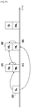
- FIG. 8 is a diagram illustrating a mechanism of transmitting channel state information, according to another embodiment of the present invention.
- the absence of the CQI for the case where the horizontal and vertical direction precodings are applied simultaneously may cause system performance degradation, as described above.
- the UE transmits RI HV 800 to the eNB.
- the eNB may acquire or recognize the horizontal and vertical direction ranks based on the RI HV 800.
- the UE transmits the horizontal direction channel state information including PMI H 810 and CQI H 820.
- the UE also transmits PMI V 830 as the horizontal channel state information, and then the CQI is acquired by taking both the horizontal and vertical direction precodings into account, i.e., CQI HV 840, along with the PMI V 830 simultaneously.
- the CQI HV 840 is the CQI acquired for the case where the horizontal and vertical direction precodings are applied. Accordingly, the rank is also determined as the function of the horizontal and vertical direction ranks.
- the UE assumes the Kronecker product of the two precoding matrices as shown in Equation (1) as the precoding applied for generating the CQI HV 840.
- This method of transmitting the horizontal and vertical direction channel state information and the CQI HV 840 from the UE to the eNB in a signal feedback process makes it possible to transmit the value of the CQI HV 840 under the assumption of the application of horizontal and vertical direction precodings.
- this method has a shortcoming in that the CQI H 820 generated under the assumption of the application of only the horizontal direction precoding has a low degree of utilization.
- FIG. 8 shows a shortcoming in that the CQI H 820 generated under the assumption of the application of only the horizontal direction precoding has a low degree of utilization.
- the reason for transmitting the CQI H 820 is because the information on the PMI H 810 and the PMI V 830 is required for transmitting CQI assuming horizontal and vertical direction precodings, but only one of the PMIs can be reported at the time of transmitting the CQI H 820.
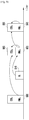
- FIG. 9 is a diagram illustrating a mechanism of transmitting channel state information, according to another embodiment of the present invention.
- the UE In the channel state information transmission method of FIG. 9 , all CQI values reported from the UE to the eNB are generated under the assumption that the horizontal and vertical direction precodings are applied unlike the embodiment of FIG. 8 .
- the UE generates CQI HV 930 under the assumption that the horizontal and vertical precoding matrices have been applied as indicated by PMI V 900 and PMI H 920.
- the UE generates the CQI HV 930 transmitted along with the PMI H 920 under the assumption that both the precoding matrix indicated by the PMI V 900, as the most recently transmitted vertical direction precoding-related information, and the precoding matrix indicated by the PMI H 920 have been applied.
- the UE generates CQI HV 950 transmitted along with PMI V 940 under the assumption that both the precoding matrix indicated by the PMI H 920, as the most recently transmitted horizontal direction precoding-related information, and the precoding matrix indicated by the PMI V 940 have been applied.
- the reason for referencing the previously transmitted PMI H or PMI V is to prevent a plurality of PMIs from being transmitted in one time duration.
- CQI HV may be transmitted only after the two precodings have been updated.
- the vertical direction rank is fixed to 1 always in the embodiment of FIG. 9 . Since the vertical direction rank is always 1, the vertical direction rank is not changed, such that the UE is capable of assuming that the precoding matrix indicated by the previously transmitted PMI V and the precoding matrix indicated by PMI V are applied simultaneously.
- the present invention may be embodied in such a way to fix the horizontal direction rank to 1.
- the UE reports RI V at every RI transmission occasion instead of RI H .
- the transmission intervals of RI, horizontal direction channel state information 920 and 930, vertical direction channel state information 940 and 950 may be configured differently depending on the system environment.
- FIG. 10 is a diagram illustrating a mechanism of transmitting channel state information, according to another embodiment of the present invention.
- the UE transmits CQI HV under the assumption that the horizontal and vertical direction precodings are applied at every CQI transmission occasion as in FIG. 9 .
- an extra RI V 1000 is transmitted to change the vertical direction rank.
- the UE notifies the eNB of the vertical direction rank to the eNB using the RI V 1000 and reports PMI V 1010 based thereon.
- CQI HV 1020 transmitted along with the PMI V 1010 is generated under the assumption that the precoding matrix indicated by the most recently transmitted RI and PMI and the precoding matrix indicated by the PMI V 1010 are applied.
- the UE updates PMI H 1040 based thereon and generates CQI HV 1050 under the assumption that the precoding indicated by the PMI V 1010 and the precoding indicated by the PMI H 1040 are applied simultaneously.
- the UE may separately update the horizontal and vertical direction ranks. Accordingly, the UE calculates the rank to be assumed for generating the channel state information CQI HV 1020 and 1050 using Equation (2). If the product of the ranks indicated by the RI V 1000 and the RI H 1030 is assumed as the rank for generating the CQI HV 1050. Accordingly, if the product of the ranks indicated by the RI V 1000 and the RI H 1030 at the time when the CQI HV 1050 is transmitted is 1, the UE transmits one CQI. If the product is equal to or greater than 2, the UE transmits two CQIs.
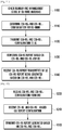
- FIG. 11 is a flowchart illustrating an eNB procedure of configuring channel state information feedback of the UE in a FD-MIMO system, according to an embodiment of the present invention.
- the eNB checks the number of transmit antennas of the FD-MIMO transmitter and 2-dimensional arrangement state, in step 1100.
- the eNB determines how to configure the horizontal and vertical CSI-RSs for use in measuring the FD-MIMO channel state information, in step 1110.
- CSI-RS H and CSI-RS V are configured in an embodiment of the present invention, the present invention may be embodied in such a way of configuring a first type CSI-RS and a second CSI-RS in another format.
- the configuration on CSI-RSH and CSI-RS V are informed to the UE through higher layer signaling or in another method, in step 1120.
- the eNB notifies the UE of the feedback scheme for the UE to transmit the channel state information corresponding to the CSI-RS H and CSI-RS V , in step 1130. Finally, the eNB receives the CSI-RSH and CSI-RS V transmitted by the UE, in step 1140. The eNB controls the system operation including scheduling based on the received channel state information.
- FIG. 12 is a flowchart illustrating a UE procedure for transmitting the channel state information based on the configuration indicated by the eNB in the FD-MIMO system, according to an embodiment of the present disclosure.
- the UE receives the information on how to receive the horizontal and vertical direction CSI-RSs, i.e., CSI-RS H and CSI-RS V , from the eNB. in step 1200.
- CSI-RS H and CSI-RS V are configured in an embodiment of the present invention, the present invention may be embodied in such a way of configuring a first type CSI-RS and a second CSI-RS in another format.
- the UE receives CSI feedback configuration information on how to measure the CSI-RS H and CSI-RS V and reports the channel state information, in step operation 1210.
- the UE measures the CSI-RSH and CSI-RSV and transmits channel state information according to the CSI feedback configuration information, in step 1220.
- the channel state information is generated and transmitted as described with reference to FIGS. 5 to 10 .
- FIGS. 11 and 12 are directed to an embodiment in which the eNB transmits CSI-RS and channel state information feedback configuration explicitly
- the present invention may be embodied in such a way that the eNB notifies the UE of at least one of CSI-RS transmission position of the eNB, number of CSI-RSs, and number of ports per CSI-RS, and the UE generates and transmits the channel state information according to a feedback configuration predetermined based on the received information. It is enough for the eNB to provide the UE with the information necessary for determining the channel state information generation and transmission method.
- FIG. 13 is a block diagram illustrating a configuration of the eNB, according to an embodiment of the present invention.
- the eNB includes a controller 1300, a transmitter 1310, and a receiver 1320.
- the controller 1300 determines the configuration on the plurality of CSI-RSs.
- the controller 1300 may determine the CSI-RS transmission scheme and the corresponding channel state information generation and feedback scheme.
- the transmitter 1310 transmits the determination result to the UE.
- the transmitter 1310 transmits the plurality of CSI-RSs to the UE.
- the receiver 1320 receives the channel state information corresponding to the CSI-RSs from the UE.
- FIG. 14 is a block diagram illustrating a configuration of the UE, according to an embodiment of the present invention.
- a receiver 1420 receives the configuration information on the plurality of CSI-RSs, and channel state information generation and feedback scheme.
- a controller 1400 controls the receiver 1420 to receive the plurality of CSI-RSs transmitted by the eNB.
- the controller 1400 generates channel state information based on the plurality of CSI-RSs.
- the controller 1400 controls a transmitter 1410 to transmit the channel state information to the eNB.
- These computer program instructions may also be stored in a computer-readable memory that can direct a computer or other programmable data processing apparatus to function in a particular manner, such that the instructions stored in the computer-readable memory produce an article of manufacture including instruction means which implement the function/act specified in the flowchart and/or block diagram block or blocks.
- the computer program instructions may also be loaded onto a computer or other programmable data processing apparatus to cause a series of operational steps to be performed on the computer or other programmable apparatus to produce a computer implemented process such that the instructions which execute on the computer or other programmable apparatus provide steps for implementing the functions/acts specified in the flowchart and/or block diagram block or blocks.
- the respective block diagrams may illustrate parts of modules, segments or codes including at least one or more executable instructions for performing specific logic function(s).
- the functions of the blocks may be performed in different order in several modifications. For example, two successive blocks may be performed substantially at the same time, or may be performed in reverse order according to their functions.?
- module means, but is not limited to, a software or hardware component, such as a Field Programmable Gate Array (FPGA) or Application Specific Integrated Circuit (ASIC), which performs certain tasks.
- a module may advantageously be configured to reside on the addressable storage medium and configured to be executed on one or more processors.
- a module may include, by way of example, components, such as software components, object-oriented software components, class components and task components, processes, functions, attributes, procedures, subroutines, segments of program code, drivers, firmware, microcode, circuitry, data, databases, data structures, tables, arrays, and variables.
- the functionality provided for in the components and modules may be combined into fewer components and modules or further separated into additional components and modules.
- the components and modules may be implemented such that they execute one or more CPUs in a device or a secure multimedia card.?
Description
- The present invention relates generally to a channel state information transmission/ reception method and apparatus and, more particularly, to a method and apparatus for transmitting and receiving channel state information in a wireless communication system supporting a plurality of antennas.
- A Reference Signal (RS) is used to measure the channel state (or quality) between a base station and users (such as, for example, signal strength and distortion, interference strength, and Gaussian noise), and is used in demodulation and decoding of a received data symbol in a wireless mobile communication system. The reference signal is also to measure a radio channel state. The receiver measures the strength of the reference signal transmitted by the transmitter at a predetermined transmit power to determine the radio channel state between the receiver and the transmitter. The receiver sends a request to the transmitter for a data rate based on the determined radio channel state.
- The 3rd generation evolved mobile communication standards such as, for example, the 3rd Generation Partnership Project Long Term Evolution-Advanced (3GPP LTE-A) and Institute of Electrical and Electronics Engineers (IEEE) 802.16m, adopt a multi-carrier multiple access technique such as Orthogonal Frequency Division Multiplexing (Multiple Access) (OFDM(A)). In the case of a multi-carrier multiple access-based wireless mobile communication system, the channel estimation and measurement performance is influenced by the number of symbols and the number of subcarriers to which the reference signal is mapped on the time-frequency resource grid. The channel estimation and measurement performance is also influenced by the power allocated for reference signal transmission. Accordingly, by allocating more radio resources (including time, frequency, and power), it is possible to improve channel estimation and measurement performance, resulting in improved received data symbol demodulation and decoding performance and channel state measurement accuracy.
- In a resource-constrained mobile communication system, however, if the radio resource is allocated for transmitting resource signals, the resource amount for data signal transmission is reduced. For this reason, the resource amount for the reference signal transmission is determined by taking the system throughput into account. Particularly, in a Multiple Input Multiple Output (MIMO) system including a plurality of antennas, a key issue is how to design and measure reference signals.
US 2012/076024 A1 relates to a method and apparatus for performing effective feedback in a wireless communication system supporting multiple antennas. -
WO 2013/187669 A1 relates to a method and an apparatus for transmitting/receiving channel state information for use in a multi-antenna system. -
EP 2 665 203 A1 -
WO2013/187669 andEP 2 665 203 - The present invention has been made to address at least the above problems and/or disadvantages and to provide at least the advantages described below. Accordingly, an aspect of the present invention provides a method and apparatus for efficiently transmitting/receiving channel state information.
- Another aspect of the present invention provides a method and apparatus for efficiently transmitting/receiving the channel state information when using a plurality of antennas.
- In accordance with an aspect of the present invention, a method for transmitting channel state information of a terminal is provided. A first Channel State Information Reference Signal (CSI-RS) and a second CSI-RS are received. Channel State Information (CSI) is generated based on both the first CSI-RS and the second CSI-RS. The CSI is transmitted.
- In accordance with another aspect of the present disclosure, a terminal for transmitting channel state information is provided. The terminal includes a receiver that receives a first CSI-RS and a second CSI-RS. The terminal also includes a controller that generates CSI based on both the first CSI-RS and the second CSI-RS. The terminal further includes a transmitter that transmits the CSI.
- The channel state information feedback method of the present invention is capable of transmitting/receiving channel state information efficiently in a wireless system using a plurality of antennas.
- The above and other aspects, features, and advantages of the present invention will be more apparent from the following detailed description when taken in conjunction with the accompanying drawings, in which:
-
FIG. 1 is a diagram illustrating a Full Dimension MIMO (FD-MIMO) system; -
FIG. 2 is a time-frequency grid illustrating a single Resource Block (RB) of a downlink subframe as a smallest scheduling unit in the LTE/LTE-A system; -
FIG. 3 is a diagram illustrating a mechanism for CSI-RS transmission in FD-MIMO system, according to an embodiment of the present invention; -
FIG. 4 is a diagram illustrating a mechanism for transmitting Rank Indicator (RI), Precoding Matrix Indicator (PMI), and Channel Quality Indicator (CQI) based on two CSI-RS in the feedback method, according to an embodiment of the present invention; -
FIG. 5 is a diagram illustrating a mechanism for transmitting channel state information, according to an embodiment of the present invention; -
FIG. 6 is a diagram illustrating a mechanism for transmitting channel state information, according to an embodiment of the present invention; -
FIG. 7 is a diagram illustrating a mechanism for transmitting channel state information, according to another embodiment of the present invention; -
FIG. 8 is a diagram illustrating a mechanism for transmitting channel state information, according to another embodiment of the present invention; -
FIG. 9 is a diagram illustrating a mechanism for transmitting channel state information, according to another embodiment of the present invention; -
FIG. 10 is a diagram illustrating a mechanism for transmitting channel state information, according to another embodiment of the present invention; -
FIG. 11 is a flowchart illustrating an eNB procedure of configuring channel state information feedback of the User Equipment (UE) in a FD-MIMO system, according to an embodiment of the present invention; -
FIG. 12 is a flowchart illustrating a UE procedure for transmitting the channel state information based on the configuration indicated by the evolved Node B (eNB) in the FD-MIMO system, according to an embodiment of the present invention; -
FIG. 13 is a block diagram illustrating a configuration of the eNB, according to an embodiment of the present invention; and -
FIG. 14 is a block diagram illustrating a configuration the UE, according to an embodiment of the present invention. - Embodiments of the present invention are described in detail with reference to the accompanying drawings. The same or similar components may be designated by the same or similar reference numerals although they are illustrated in different drawings. Detailed descriptions of constructions or processes known in the art may be omitted to avoid obscuring the subject matter of the present disclosure.
- The following terms are defined in consideration of the functionality in embodiments of the present invention, and may vary according to the intention of a user or an operator, usage, etc. Therefore, the definition should be made on the basis of the overall content of the present specification.
- Although the description is directed to an OFDM-based radio communication system, particularly, the 3GPP Evolved Universal Terrestrial Radio Access (E-UTRA), it will be understood by those skilled in the art that embodiments of the present invention can be applied to other communication systems having a similar technical background and channel format, with a slight modification, without departing from the scope of the present invention.
- Embodiments of the present invention relate to a wireless mobile communication system and, in particular, to a method for efficiently transmitting/receiving channel state information in a wireless mobile communication system operating with a multicarrier multiple access scheme such as, for example, Orthogonal Frequency Division Multiple Access (OFDMA).
- Mobile communication systems have evolved into high-speed, high-quality wireless packet data communication systems that provide data and multimedia services beyond the early voice-oriented services. Recently, various mobile communication standards, such as, for example, High Speed Downlink Packet Access (HSDPA), High Speed Uplink Packet Access (HSUPA), LTE, and LTE-A defined in 3rd Generation Partnership Project (3GPP), High Rate Packet Data (HRPD) defined in 3rd Generation Partnership Project-2 (3GPP2), and 802.16 defined in IEEE, have been developed to support the high-speed, high-quality wireless packet data communication services.
- Existing 3rd generation mobile communications, including LTE, Ultra Mobile Broadband (UMB), and 802.16m, operate based on a multi-carrier multiple access scheme and adopt Multiple Input Multiple Output (MIMO) with channel sensitive scheduling, such as beamforming and Adaptive Modulation and Coding (AMC), to improve transmission efficiency. These techniques increase the system throughput by improving transmission efficiency in such a way as to concentrate transmit power of a plurality of antennas, adjusting an amount of transmit data, and selectively transmitting data to the user with a best channel quality. Since most of these techniques operate based on the channel state information between the base station (eNB) and the terminal (UE or Mobile Station (MS)), the eNB or UE has to measure the channel state between the eNB and the UE. At this time, the signal used for channel state measurement is a Channel State Indication Reference Signal (CSI-RS). The eNB is a transmitter in downlink and a receiver in uplink. The one eNB may manage a plurality of cells for transmission/reception. A mobile communication system includes a plurality of eNBs distributed geographically, and each eNB performs transmission/reception through a plurality of cells.
- Existing 3rd and 4th Generation mobile communication systems represented by LTE/ LTE-A adopt a MIMO scheme with a plurality of transmit and receive antennas to transmit a plurality of information streams as spatially separated. This technique of transmitting the plurality of information streams as spatially separated is referred to as spatial multiplexing. Typically, the number of information streams capable of being spatially multiplexed depends on the number of antennas of the transmitter and the receiver. The number of information streams that can be spatially multiplexed is referred to rank in general. In the case of the MIMO scheme till the standard of LTE/ LTE-A Release 11, the spatial multiplexing of up to 8 x 8 antennas and up to rank 8 are supported.
- The FD-MIMO system, to which a technique proposed in an embodiment of the present invention is applied, has been evolved from the LTE/LTE-A MIMO system supporting up to 8 transmit antennas so as to support 32 or more transmit antennas. However, the scope of the present invention is not limited thereto.
-
FIG. 1 is a diagram illustrating an FD-MIMO system. The FD-MIMO system is a wireless communication system that is capable of transmitting data using a few dozen or more transmit antennas. - Referring to
FIG. 1 , abase station transmitter 100 transmitsradio signals antennas 110 are arranged at a minimum distance among each other. The minimum distance may be half of the wavelength (λ/2) of the radio signal. Typically, when the transmit antennas are arranged at the distance of half of the wavelength of the radio signal, the signals transmitted by the respective transmit antennas are influenced by the radio channel with low correlation. Assuming a radio signal band of 2GHz, this distance is 7.5 cm, and is shortened as the band becomes higher than 2GHz. - In
FIG. 1 , a few dozen or more transmitantennas 110 arranged at the base station are used to transmit signals to one or more terminals as denoted byreference numerals - In order to efficiently implement the FD-MIMO system, the terminal has to accurately measure the channel condition and interference size and efficiently transmit the channel state information to the base station. If the channel state information is received, the base station determines the terminals for downlink transmission, downlink data rate, and precoding to be applied. In the case of an FD-MIMO system using a large number of transmit antennas, if the channel state information transmission method of the legacy LTE/LTE-A system is applied without modification, the amount of control information to be transmitted in uplink significantly increases, resulting in uplink overhead.
- The mobile communication system is restricted in resources such as, for example, time, frequency, and transmission power. Accordingly, if a resource allocated for a reference signal increases, the resource amount to be allocated for data traffic channel transmission decreases, resulting in a reduction in the amount of data transmission. Although the channel estimation and measurement performance are improved, the data transmission amount decreases, resulting in reduction of entire system throughput. Thus, there is a need for efficiently allocating resources for reference signal and traffic channel transmissions in order to maximize the entire system throughput.
-
FIG. 2 is a time-frequency grid illustrating a single RB of a downlink subframe as a smallest scheduling unit in the LTE/LTE-A system. - As shown in
FIG. 2 , the radio resource is of one subframe in the time domain and one RB in the frequency domain. The radio resource consists of 12 subcarriers in the frequency domain and 14 OFDM symbols in the time domain, i.e., 168 unique frequency-time positions. In LTE/LTE-A, each frequency-time position is referred to as a Resource Element (RE). - The radio resource structured as shown in
FIG. 2 can be used for transmitting different types of signals as follows. - 1. Cell-specific Reference Signal (CRS): reference signal transmitted to all the UEs within a cell
- 2. Demodulation Reference Signal (DMRS): reference signal transmitted to a specific UE
- 3. Physical Downlink Shared Channel (PDSCH): data channel transmitted in downlink, which the eNB uses to transmit data to the UE, and mapped to REs not used for reference signal transmission in a data region of
FIG. 2 - 4. Channel State Information Reference Signal (CSI-RS): reference signal transmitted to the UEs within a cell and used for channel state measurement. Multiple CSI-RSs can be transmitted within a cell
- 5. Physical Hybrid-ARQ Indicator Channel (PHICH), Physical Control Format Indicator Channel (PCFICH), Physical Downlink Control Channel (PDCCH): channels for providing a control channel necessary for the UE to receive PDCCH and transmitting ACK/NACK of HARQ operation for uplink data transmission
- In addition to the above signals, zero power CSI-RS can be configured in order for the UEs within the corresponding cells to receive the CSI-RSs transmitted by different eNBs in the LTE-A system. The zero power CSI-RS (muting) can be mapped to the positions designated for CSI-RS, and the UE receives the traffic signal skipping the corresponding radio resource in general. In the LTE-A system, the zero power CSI-RS is referred to as muting. The zero power CSI-RS (muting) by nature is mapped to the CSI-RS position without transmission power allocation.
- In
FIG. 2 , the CSI-RS can be transmitted at some of the positions marked by A, B, C, D, E, F, G, H, I, and J, according to the number of number of antennas transmitting CSI-RS. Also, the zero power CSI-RS (muting) can be mapped to some of the positions A, B, C, D, E, F, G, H, I, and J. The CSI-RS can be mapped to 2, 4, or 8 REs, according to the number of antenna ports for transmission. For two antenna ports, half of a specific pattern is used for CSI-RS transmission. For four antenna ports, an entire specific pattern is used for CSI-RS transmission. For eight antenna ports, two patterns are used for CSI-RS transmission. Muting is always performed by pattern. Specifically, although muting may be applied to a plurality of patterns, if the muting positions mismatch CSI-RS positions, it cannot be partially applied to one pattern. - When transmitting CSI-RSs of two antenna ports, the CSI-RSs are mapped to two consecutive REs in the time domain and distinguished from each other using orthogonal codes. When transmitting CSI-RSs of four antenna ports, the CSI-RSs are mapped in the same way of mapping the two more CSI-RSs to two more consecutive REs. This is applied to the case of transmitting CSI-RSs of eight antenna ports.
- In a cellular system, the reference signal has to be transmitted for downlink channel state measurement. In the case of the 3GPP LTE-A system, the UE measures the channel state with the eNB using the CSI-RS transmitted by the eNB. The channel state is measured in consideration of a few factors including downlink interference. The downlink interference includes the interference caused by the antennas of neighbor eNBs and thermal noise that are important in determining the downlink channel condition. For example, when an eNB with one transmit antenna transmits a reference signal to a UE with one receive antenna, the UE has to determine an energy per symbol that can be received in downlink and an interference amount that may be received for the duration of receiving the corresponding symbol to calculate Es/Io from the received reference signal. The calculated Es/Io is reported to the eNB such that the eNB determines the downlink data rate for the UE.
- In the LTE-A system, the UE feeds back the information on the downlink channel state for use in downlink scheduling of the eNB. Specifically, the UE measures the reference signal transmitted by the eNB in downlink and feeds back the information estimated from the reference signal to the eNB in the format defined in LTE/LTE-A standard. In LTE/LTE-A, the UE feedback information includes the following three indicators:
- 1. RI: number of spatial layers that can be supported by the current channel experienced at the UE
- 2. PMI: precoding matrix recommended by the current channel experienced at the UE
- 3. CQI: maximum possible data rate that the UE can receive signals in the current channel state. CQI may be replaced with the SINR, a maximum error correction code rate and modulation scheme, or per-frequency data efficiency that can be used in a similar way to the maximum data rate.
- The RI, PMI, and CQI have associated meanings. For example, the precoding matrix supported in LTE/LTE-A is configured differently per rank. Accordingly, the PMI value 'X' is interpreted differently for the cases of RI set to 1 and RI set to 2. Also, when determining CQI, the UE assumes that the PMI and RI, which it has reported, are applied by the eNB. Specifically, if the UE reports RI_X, PMI_Y, and CQI_Z; this means that the UE is capable of receiving the signal at the data rate corresponding to CQI_Z when the rank RI_X and the precoding matrix PMI_Y are applied. In this way, the UE calculates CQI with which the optimal performance is achieved in real transmission under the assumption of the transmission mode to be selected by the eNB.
- Typically, in FD-MIMO using a plurality of transmit antennas, the number of CSI-RSs has to increase in proportion to the number of transmit antennas. For an LTE/ LTE-A using 8 transmit antennas, the eNB has to transmit CSI-RSs of 8 ports to the UE for downlink channel state measurement. In order to transmit 8-port CSI-RSs, 8 REs must be allocated for CSI-RS transmission in one RB. For example, the REs indicated by A and B can be used for CSI-RS transmission of the corresponding eNB. When applying a CSI-RS transmission scheme of LTE/LTE-A to FD-MIMO, the CSI-RS transmission resource increases in proportion to the number of transmit antennas. Specifically, the eNB having 128 transmit antennas has to transmit CSI-RS on 128 REs in one RB. Such a CSI-RS transmission scheme consumes excessive radio resources, and thus, causes a shortage of resources for data transmission.
- For the eNB having a plurality of transmit antennas, an FD-MIMO may transmit CSI-RSs on N dimensions such that the UE performs channel measurements for a plurality of transmit antennas without excessive resource allocation for CSI-RS transmission. As shown in
FIG. 1 where the transmitantennas 110 of the eNB are arranged 2-dimensionally, the CSI-RSs may be transmitted as separated into 2 dimensions. One CSI-RS is used as a horizontal CSI-RS for acquiring the horizontal direction channel information, while the other CSI-RS is used as a vertical CSI-RS for acquiring vertical direction channel information. -
FIG. 3 is a diagram illustrating a mechanism of CSI-RS transmission in FD-MIMO system, according to an embodiment of the present invention. - Referring to
FIG. 3 , the eNB operating in FD-MIMO mode has total 32 antennas. The number of antennas may vary depending on the embodiment. InFIG. 3 , 32antennas 300 are indicated by A0, ..., A3, B0, ..., B3, C0, ..., C3, D0, ..., D3, E0, ..., E3, F0, ..., F3, G0,..., G3, and H0, ..., H3. Two CSI-RSs are transmitted through the 32 antennas. The antenna ports corresponding to H-CSI-RS for use in measuring horizontal channel state consist of the following 8 antenna ports. - 1. H-CSI-RS port 0: group of antennas A0, A1, A2, and A3
- 2. H-CSI-RS port 1: group of antennas B0, B1, B2, and B3
- 3. H-CSI-RS port 2: group of antennas C0, C1, C2, and C3
- 4. H-CSI-RS port 3: group of antennas D0, D1, D2, and D3
- 5. H-CSI-RS port 4: group of antennas E0, E1, E2, and E3
- 6. H-CSI-RS port 5: group of antennas F0, F1, F2, and F3
- 7. H-CSI-RS port 6: group of antennas G0, G1, G2, and G3
- 8. H-CSI-RS port 7: group of antennas H0, H1, H2, and H3
- The grouping a plurality of antennas into one CSI-RS port is a concept referred to as antenna virtualization. Typically, antenna virtualization is performed through linear combination of a plurality of antennas. The antenna ports corresponding to V-CSI-RS for use in measuring vertical channel state consist of the following 4 antenna ports.
- 1. V-CSI-RS port 0: group of antennas A0, B0, C0, D0, E0, F0, G0, and H0
- 2. V-CSI-RS port 1: group of antennas A1, B1, C1, D1, E1, F1, G1, and H1
- 3. V-CSI-RS port 2: group of antennas A2, B2, C2, D2, E2, F2, G2, and H2
- 4. V-CSI-RS port 3: group of antennas A3, B3, C3, D3, E3, F3, G3, and H3
- It is assumed that a plurality of antennas are arranged 2-dimensionally as described above. The antennas are arranged orthogonally forming M rows in the vertical direction and N columns in the horizontal direction. The UE is capable of measuring FD-MIMO channels using N H-CSI-RS ports and M V-CSI-RS ports. As aforementioned, if two CSI-RSs are used, the channel state information can be acquired using M+N CSI-RS ports for M×N transmit antennas. Since the channel information on a large number of transmit antennas is acquired using a relatively small number of CSI-RS ports, it is advantageous in reducing the CSI-RS overhead. Although embodiments of the present invention are directed to channel information on the FD-MIMO transmit antennas using two CSI-RSs, this approach can be applied to the cases of using two or more CSI-RSs.
- In
FIG. 3 , the RSs of the 32 transmit antennas are mapped to 8 H-CSI-RS ports and 4 V-CSI-RS ports, and the UE measures the radio channels using the CSI-RSs of the FD-MIMO system. The H-CSI-RS can be used for estimating the horizontal angle between the UE and the eNB transmit antennas as denoted byreference numeral 310, while the V-CSI-RS can be used for estimating the vertical angle between the UE and the eNB transmit antennas as denoted byreference numeral 320. - The following abbreviations are used throughout the specification.
- ?RIH: RI generated based on H-CSI-RS for feedback to the eNB
- ?RIV: RI generated based on V-CSI-RS for feedback to the eNB
- ?RIHV: RI generated based on H-CSI-RS and V-CSI-RS for feedback to the eNB
- ?PMIH: PMI generated based on H-CSI-RS for feedback to the eNB
- ?PMIV: PMI generated based on V-CSI-RS for feedback to the eNB
- ?CQIH: UE-recommended data rate generated under the assumption that only the horizontal direction precoding matrix is applied
- ?CQIV: UE-recommended data rate generated under the assumption that only the vertical precoding matrix is applied
- ?CQIHV: UE-recommended data rage generated under the assumption that both the horizontal and vertical precoding matrices are applied
- The following description is directed to the case of using the horizontal direction channel state information and the vertical direction channel state information. When an eNB operates with two or more CSI-RSs, however, other types of channel state information can also be applied to the horizontal and vertical direction channel state information. In an embodiment of the present invention where the CSI-RS mapped to an antenna port from the first view point (first CSI-RS) and the CSI-RS mapped to an antenna port from the second view point (second CSI-RS) are used, the UE is capable of acquiring the channel state information (first and second channel state information) based on the two respective CSI-RSs and the channel state information (third channel state information) based on both the CSI-RSs. The configuration described in the following description is applicable to various embodiments in similar manner. The following description is directed to an embodiment of the present invention using V-CSI-RS and H-CSI-RS.
- In the following description, the channel state information corresponding to the vertical direction CSI-RS is referred to as vertical direction channel state information. The vertical direction channel state information includes at least one of RI, PMI, and CQI acquired based on the vertical direction CSI-RS.
- In the following description, the channel state information corresponding to the horizontal direction CSI-RS is referred to as horizontal direction channel state information. The horizontal channel state information includes at least one of RI, PMI, and CQI acquired based on the horizontal direction CSI-RS.
- When the eNB sends the UE two or more CSI-RSs, the UE is capable of transmitting the channel state information corresponding to the respective CSI-RSs. Each of the channel state information includes at least one of RI, PMI, and CQI. However, the UE may acquire the channel state information based on the two or more CSI-RSs in an embodiment of the present invention. Acquisition of the channel state information is described in greater detail below.
-
FIG. 4 is a diagram illustrating a mechanism of transmitting RI, PMI, and CQI based on two CSI-RS in the feedback method, according to an embodiment of the present disclosure. The UE reports the radio channel state information of the FD-MIMO to the eNB by transmitting RI, PMI, and CQI for the respective CSI-RSs. - In
FIG. 4 , the arrow indicates how a certain type of channel state information is related to other types of channel state information. The arrow starting fromRIv 400 and ending atPMIv 410 indicates that thePMIv 410 is interpreted differently according to the value ofRIv 400. Specifically, the arrow means that the UE uses the value of theRI V 400 to interpretCQI V 420. Likewise, the UE uses the value ofRI H 430 to interpretPMI H 440. - In
FIG. 4 , the UE measures the V-CSI-RS and transmits the channel state information in the method indicated by "Feedback 1". The UE also measures the H-CSI-RS and transmits the channel state information in the method indicated by "Feedback 2". Here, RI, PMI, and CQI are transmitted in the state of being correlated among each other. In the case of "Feedback 1", theRI V 400 notifies of the rank of the precoding matrix indicated by thePMI V 410. Also, theCQI V 420 indicates the data rate at which the UE can receive data or a corresponding value in the case of applying the precoding matrix of the corresponding rank which is indicated by thePMI V 410, when the transmission is performed at the rank indicated by theRI V 400. In the case of "Feedback 2", theRI 430, thePMI 440, andCQI 450 are transmitted in the state of being correlated among each other like the case of "Feedback 1". - As shown in
FIG. 4 , one of the channel state information report methods may configure a plurality of feedback for a plurality of transmit antennas of the FD-MIMO eNB, and make the UE report channel state information to the eNB. This method is advantageous in that the UE is capable of generating and reporting channel state information for FD-MIMO without extra implementation. - However, in the channel state information report method of
FIG. 4 , it is difficult to achieve enough throughput of the FD-MIMO system. This is due to the fact that although the UE configures a plurality of feedback to report the channel state information to the eNB, the CQI is generated without an assumption on the precoding when the FD-MIMO is applied. - When a plurality of transmit
antennas 110 of the FD-MIMO system are arranged 2-dimentinally, as shown inFIG. 3 , both the vertical direction precoding matrix and the horizontal direction precoding matrix are applied to the signal transmitted by the UE. Specifically, the UE receives the signal to which the precoding matrices corresponding to thePMI H 440 and thePMI V 410 other than the signal to which one of thePMI H 440 and thePMI V 410. - If only the
CQI H450 and theCQI V420 corresponding to precodings indicated by therespective PMI H 440 andPMI V 410 are reported to the eNB, the eNB has to determine the CQI to which both the vertical and horizontal direction precoding matrices are applied, without receipt of such a CQI. If the eNB determines the CQI to which both the vertical and horizontal direction precoding matrices are applied arbitrarily, this may cause degradation of system performance. - As described above, one of the methods for mitigating the use of radio resource for CSI-RS transmission in the FD-MIMO system is to make the UE measure a plurality CSI-RSs capable of efficiently estimating a plurality of transmit antennas. Each CSI-RS can be used for the UE to measure the channel state of one of a plurality dimensions for measuring one radio channel. This method requires a relatively small amount of radio resources for CSI-RS transmission as compared to the method of allocating a unique CSI-RS ports for the respective transmit antennas. For example, when using two CSI-RSs in the vertical and horizontal direction for the transmit antennas of the FD-MIMO that are arranged in the form of a rectangle, the UE is capable of efficiently measuring the channel state. Embodiments of the present invention propose a novel technology and apparatus that is capable of allowing the UE to measure a plurality of CSI-RSs and efficiently report the channel state information in the FD-MIMO system including a plurality of transmit antennas.
-
FIG. 5 is a diagram illustrating a mechanism of transmitting channel state information, according to an embodiment of the present disclosure. - In
FIG. 5 , the channel state information corresponding to the two CSI-RSs are reported as in the embodiment ofFIG. 4 . The channel state information transmission method is indicated by "Feedback 1" as in the embodiment ofFIG. 4 . Specifically, the UE measures V-CSI-RS to reportRI V 500,PMI V 510, andCQI V 520 to the eNB. The embodiment ofFIG. 5 differs from the embodiment ofFIG. 4 in the procedure of indication with "Feedback 2". The UE reports the CQI for the case where the precoding is applied in both the vertical and horizontal directions, i.e.,CQI HV 550, to the eNB. Specifically, the UE reports to the eNB the mostrecent PMI V 510 generated in the procedure indicated with "Feedback 1" andCQI HV 550 generated in the case where the precodings indicated byPMI 540, which is determined optimal based on the H-CSI-RS measurement. - In the embodiment of
FIG. 5 , the UE measures the V-CSI-RS to generate theRI V 500, which is reported to the eNB. The UE determines thePMI V 510 optimal to thecorresponding rank 500 and reports theCQI V 520 when the precoding indicated by thePMI V 510 is applied. The UE measures H-CSI-RS to generateRI 530, which is reported to the eNB. The UE reports to the eNB theCQI HV 550 generated by applying the precoding indicated byPMI 540 optimal to thecorresponding rank 530 and the precoding indicated by the previously transmittedPMI V 510. - As shown in
FIG. 5 , in order for the UE to report the CQI value for the case where the precoding matrix indicated by thePMI H 540 and the precoding matrix indicated by thePMI V 510 are allocated simultaneously to the eNB, the following may be required. - First, it is required to define a function for determining whether to take two PMIs into consideration to determine at least one of two CQIs. Specifically, the eNB notifies the UE of the correlation of the feedback information in configuring a plurality of feedbacks to the UE, and the UE generates CQI based thereon. In the case of
FIG. 5 , a control message instructing to calculate the second CQI, i.e., theCQI HV 550, by applying the first PMI, i.e. thePMI V 510, and the second PMI, i.e. thePMI H 540, together has to be transmitted from the eNB to the UE. - Second, it is required to define how to determine CQI in the case of applying a plurality of precodings. When calculating a CQI when only one precoding is applied, the UE calculates CQI under the assumption that the precoding indicated by RI and PMI it has reported is applied in downlink. However, in the case of the
CQI HV 550, the UE calculates CQI under the assumption that two precodings are simultaneously applied in downlink. The UE may interpret the application of two precodings as the Kronecker product. The Kronecker product is defined with two matrices as shown in Equation (1) below.
In Equation (1), A and B denote matrices, and a11 to amn denote elements of matrix A, and aij denotes the element at ith row and jth column. - In Equation (1), the UE is capable of acquiring the precoding matrix for the case where two precoding matrices are applied simultaneously by replacing A and B with the precoding matrices indicated by the
PMI H 540 and thePMI V 510. When calculating theCQI HV 550, the UE calculates theCQI HV 550 under the assumption that the precoding matrix acquired by applying the Equation (1) to the precoding matrices indicated by thePMI H 540 andPMI V 510 is applied in downlink. - In order to acquire the precoding matrix for the case where the two precoding matrices are applied using the Kronecker product of Equation (1), it is necessary for the UE and eNB to operate differently depending on the rank reported by the UE. Three embodiments are proposed for this purpose.
- The eNB configures one of the
RI V 500 and theRI H530 withrank 1 always. For example, if theCQI HV 550 is reported along with theRI H530 to the eNB, theRI V 500 is restricted to be always set to 1. The rank supported in the case where two precoding matrices are applied simultaneously is determined depending on theRI H530. Specifically, when theRI H530 is set to 1, the UE is capable of supportingrank 1; and when theRI H530 is set to 2, the UE is capable of supportingrank 2. The UE and the eNB operate in the FD-MIMO system under this assumption. Although two CSI-RSs are assumed in this embodiment of the present invention, if the number of CSI-RS is 3 or more, RIs have to be set to 1 with the exception of the RI corresponding to one CSI-RS. - When the vertical and horizontal direction precoding matrices are applied simultaneously, the eNB and the UE determine the rank supportable by the UE using Equation (2) set forth below.

- Specifically, the UE and the eNB exchange the channel state information under the assumption that the rank for the case where the vertical and horizontal direction precoding matrices are applied simultaneously is the product of the two ranks supportable in the respective directions. For example, if the UE reports the RIH set to 2 and RIV set to 3 to the eNB, the eNB and the UE assume that the rank for the case where all of the precoding matrices are applied is 6.
- In LTE/LTE-A, if the UE reports to the eNB the RI corresponding to rank 2 or higher, two CQI values are reported to the eNB. This is due to the fact that the eNB transmits two codewords to the UE, and thus, the UE has to separately report the CQIs corresponding to respective codewords.
- When the method of Equation (2) is applied to the embodiment of
FIG. 5 , if the rank for the case where the precodings obtained by Equation (2) is 2 or higher although theRI H 530 is set to 1, the UE transmits the two CQIs in the form of theCQI HV 550. Also, if the rank for the case where all of the precodings obtained by Equation (2) is 2 or higher, the eNB receives the two CQIs under the assumption that they are transmitted in the form of theCQI HV 550. - In the method of measuring, at the UE, the horizontal and vertical direction channel state information corresponding to two CSI-RS and reporting the channel state information to the eNB, as shown in
FIG. 4 or5 , transmission of "Feedback 1" and "Feedback 2" may cause collision. The term 'collision' refers to a situation in which transmission of "Feedback 1" and "Feedback 2" is required at the same time. If any collision is predicted, the UE may report the channel state information of one of "Feedback 1" and "Feedback 2". The FD-MIMO operation with the configuration of a plurality of feedback, as shown inFIG. 4 or5 , may cause the channel state information to be partially missed. -
FIG. 6 is a diagram illustrating a mechanism of transmitting channel state information, according to an embodiment of the present invention. - Although the UE reports the channel state information corresponding to two CSI-RSs, the feedback method of
FIG. 6 differs from that ofFIG. 4 in that the feedback is completed in only one feedback process. Referring toFIG. 6 , the UE transmitsRI HV 600 to report the horizontal and vertical direction ranks. Table 1 shows horizontal and vertical direction ranks (first second ranks). -
[Table 1] RIHV Horizontal direction rank Vertical direction rank 000 1 1 001 2 1 010 3 1 011 4 1 100 1 2 101 2 2 110 3 2 111 4 2 - The eNB may acquire the horizontal and vertical direction ranks from the
RI HV 600 transmitted by the UE. The UE determines the value of theRI HV 600 based on both the two CSI-RS, i.e., H-CSI-RS and V-CSI-RS. The eNB checks the information on the horizontal and vertical direction precodings and UE-supportable data rate based onPMIs FIGS. 4 and5 . InFIG. 6 , the horizontal and vertical direction ranks may have different values depending on the value of theRI HV 600 reported by the UE. Specifically, the precoding matrix indicated by thePMI H 610 is determined depending on the horizontal direction PMI indicated by the value of theRI HV 600. The UE also transmits CQI obtained under the assumption of the case where the precoding matrix indicated by theRI H 610 is applied, i.e., theCQI H 620. In order to determine the values of thePMI H 610 and theCQI H 620, the UE measures the H-CSI-RS. Likewise, the precoding matrix indicated by thePMI V 630 is determined depending on the vertical direction rank indicated by theRI HV 600. The UE also transmits CQI obtained under the assumption of the case where the precoding matrix indicated by thePMI V 630 is applied, i.e., theCQI V 640. In order to determine the values ofPMI V 630 andCQI V 640, the UE measures V-CSI-RS. - Referring to
FIG. 6 , the UE alternately transmits the horizontalchannel state information channel state information - In a real system, however, such a method may not be appropriate. Specifically, it may advantageous for the UE to report specific direction channel state information at an interval shorter than that of the other direction channel state information in view of system throughput optimization. In order for the UE to report channel state information corresponding to a plurality of CSI-RSs to the eNB at different intervals, it is preferred for the eNB to perform configuration thereon. Specifically, in the case that the UE reports different direction channel state information to the eNB in one feedback process, the eNB may notify the UE of the following information for configuration thereon.
- Feedback interval and frame offset for horizontal direction channel state information (CQIH, PMIH), i.e., first channel state information
- Feedback interval and frame offset for vertical direction channel state information (CQIV and PMIV), i.e., second channel state information
- The subframe offset value is the value determining the subframe position for real transmission in a period. For example, if the period is 10 milliseconds (msec) and the subframe offset is 5, this means that the corresponding signal is transmitted at the subframe 5 in the period of 10 milliseconds.
- In
FIG. 6 , the horizontal and vertical direction ranks reported from the UE to the eNB may be determined depending on different rank restrictions. The rank restriction is to restrict, when the UE measures the RS to determine the rank, the maximum value to the value preconfigured by the eNB. In the mobile communication system, if the eNB is allowed to restrict the maximum value of the rank for the UE, it can be interpreted as a part of the optimization procedure for controlling the system in the eNB-preferred way. In order to apply the rank restriction to the respective horizontal and vertical direction ranks, the eNB may notify the UE of the following information through higher layer signaling or in another method. - 1. Maximum value of horizontal direction rank
- 2. Maximum value of vertical direction rank
-
FIG. 7 is a diagram illustrating a mechanism of transmitting channel state information, according to another embodiment of the present invention. In the embodiment ofFIG. 7 , the UE reports the channel state information to the eNB in one feedback process as in the embodiment ofFIG. 6 . However, the embodiment ofFIG. 7 differs from the embodiment ofFIG. 6 in that the horizontal and vertical direction ranks are reported withRI H700 andRI V 730 separately, rather than withRI HV 600. - Referring to
FIG. 7 , theRI H700 is reported and then followed byPMI H 710 andCQI H 720 based thereon. Also, theRI V 730 is reported and then followed byPMI V 740 andCQI V 750 based thereon. Although theRI H700 and theRI V 730 are reported separately, the intervals and ranks of the horizontal and vertical channel state information may be configured differently, as in the embodiment ofFIG. 6 . -
FIG. 8 is a diagram illustrating a mechanism of transmitting channel state information, according to another embodiment of the present invention. - When the UE reports the channel state information corresponding to a plurality of CSI-RSs in a signal feedback process, as in the embodiments of
FIGS. 6 and7 , the absence of the CQI for the case where the horizontal and vertical direction precodings are applied simultaneously may cause system performance degradation, as described above. - Referring to
FIG. 8 , the UE transmitsRI HV 800 to the eNB. The eNB may acquire or recognize the horizontal and vertical direction ranks based on theRI HV 800. The UE transmits the horizontal direction channel stateinformation including PMI H 810 andCQI H 820. The UE also transmitsPMI V 830 as the horizontal channel state information, and then the CQI is acquired by taking both the horizontal and vertical direction precodings into account, i.e.,CQI HV 840, along with thePMI V 830 simultaneously. TheCQI HV840 is the CQI acquired for the case where the horizontal and vertical direction precodings are applied. Accordingly, the rank is also determined as the function of the horizontal and vertical direction ranks. The UE assumes the Kronecker product of the two precoding matrices as shown in Equation (1) as the precoding applied for generating theCQI HV840. - This method of transmitting the horizontal and vertical direction channel state information and the
CQI HV 840 from the UE to the eNB in a signal feedback process, as shown inFIG. 8 , makes it possible to transmit the value of theCQI HV 840 under the assumption of the application of horizontal and vertical direction precodings. However, this method has a shortcoming in that theCQI H 820 generated under the assumption of the application of only the horizontal direction precoding has a low degree of utilization. InFIG. 8 , the reason for transmitting theCQI H 820 is because the information on thePMI H 810 and thePMI V 830 is required for transmitting CQI assuming horizontal and vertical direction precodings, but only one of the PMIs can be reported at the time of transmitting theCQI H 820. -
FIG. 9 is a diagram illustrating a mechanism of transmitting channel state information, according to another embodiment of the present invention. - In the channel state information transmission method of
FIG. 9 , all CQI values reported from the UE to the eNB are generated under the assumption that the horizontal and vertical direction precodings are applied unlike the embodiment ofFIG. 8 . InFIG. 9 , the UE generatesCQI HV 930 under the assumption that the horizontal and vertical precoding matrices have been applied as indicated byPMI V 900 andPMI H920. Specifically, the UE generates theCQI HV 930 transmitted along with thePMI H920 under the assumption that both the precoding matrix indicated by thePMI V 900, as the most recently transmitted vertical direction precoding-related information, and the precoding matrix indicated by thePMI H920 have been applied. Likewise, the UE generatesCQI HV 950 transmitted along withPMI V 940 under the assumption that both the precoding matrix indicated by thePMI H 920, as the most recently transmitted horizontal direction precoding-related information, and the precoding matrix indicated by thePMI V940 have been applied. The reason for referencing the previously transmitted PMIH or PMIV is to prevent a plurality of PMIs from being transmitted in one time duration. - In order to transmit CQIHV at every CQI transmission occasion, as shown in
FIG. 9 , it is necessary to restrict the rank in a specific direction. In order to change the horizontal and vertical direction ranks simultaneously, the horizontal and vertical direction precodings also have to be updated according to the changed rank values. CQIHV may be transmitted only after the two precodings have been updated. By taking notice of this, it is assumed that the vertical direction rank is fixed to 1 always in the embodiment ofFIG. 9 . Since the vertical direction rank is always 1, the vertical direction rank is not changed, such that the UE is capable of assuming that the precoding matrix indicated by the previously transmitted PMIV and the precoding matrix indicated by PMIV are applied simultaneously. Although the description is directed to the case where the vertical direction rank is fixed to 1, the present invention may be embodied in such a way to fix the horizontal direction rank to 1. When the horizontal direction rank is fixed to 1, the UE reports RIV at every RI transmission occasion instead of RIH. - In
FIG. 9 , the transmission intervals of RI, horizontal directionchannel state information channel state information -
FIG. 10 is a diagram illustrating a mechanism of transmitting channel state information, according to another embodiment of the present invention. - In
FIG. 10 , the UE transmits CQIHV under the assumption that the horizontal and vertical direction precodings are applied at every CQI transmission occasion as inFIG. 9 . In the embodiment ofFIG. 10 , however, anextra RI V 1000 is transmitted to change the vertical direction rank. Specifically, the UE notifies the eNB of the vertical direction rank to the eNB using theRI V 1000 andreports PMI V 1010 based thereon.CQI HV 1020 transmitted along with thePMI V 1010 is generated under the assumption that the precoding matrix indicated by the most recently transmitted RI and PMI and the precoding matrix indicated by thePMI V 1010 are applied. When the horizontal direction rank is updated withRI H 1030, the UE updatesPMI H 1040 based thereon and generatesCQI HV 1050 under the assumption that the precoding indicated by thePMI V 1010 and the precoding indicated by thePMI H 1040 are applied simultaneously. - In
FIG. 10 , the UE may separately update the horizontal and vertical direction ranks. Accordingly, the UE calculates the rank to be assumed for generating the channelstate information CQI RI V 1000 and theRI H 1030 is assumed as the rank for generating theCQI HV 1050. Accordingly, if the product of the ranks indicated by theRI V 1000 and theRI H 1030 at the time when theCQI HV 1050 is transmitted is 1, the UE transmits one CQI. If the product is equal to or greater than 2, the UE transmits two CQIs. -
FIG. 11 is a flowchart illustrating an eNB procedure of configuring channel state information feedback of the UE in a FD-MIMO system, according to an embodiment of the present invention. - In
FIG. 11 , the eNB checks the number of transmit antennas of the FD-MIMO transmitter and 2-dimensional arrangement state, instep 1100. The eNB determines how to configure the horizontal and vertical CSI-RSs for use in measuring the FD-MIMO channel state information, instep 1110. Although CSI-RSH and CSI-RSV are configured in an embodiment of the present invention, the present invention may be embodied in such a way of configuring a first type CSI-RS and a second CSI-RS in another format. The configuration on CSI-RSH and CSI-RSV are informed to the UE through higher layer signaling or in another method, instep 1120. The eNB notifies the UE of the feedback scheme for the UE to transmit the channel state information corresponding to the CSI-RSH and CSI-RSV, instep 1130. Finally, the eNB receives the CSI-RSH and CSI-RSV transmitted by the UE, instep 1140. The eNB controls the system operation including scheduling based on the received channel state information. -
FIG. 12 is a flowchart illustrating a UE procedure for transmitting the channel state information based on the configuration indicated by the eNB in the FD-MIMO system, according to an embodiment of the present disclosure. - The UE receives the information on how to receive the horizontal and vertical direction CSI-RSs, i.e., CSI-RSH and CSI-RSV, from the eNB. in
step 1200. Although CSI-RSH and CSI-RSV are configured in an embodiment of the present invention, the present invention may be embodied in such a way of configuring a first type CSI-RS and a second CSI-RS in another format. The UE receives CSI feedback configuration information on how to measure the CSI-RSH and CSI-RSV and reports the channel state information, instep operation 1210. The UE measures the CSI-RSH and CSI-RSV and transmits channel state information according to the CSI feedback configuration information, instep 1220. The channel state information is generated and transmitted as described with reference toFIGS. 5 to 10 . - Although the embodiments of
FIGS. 11 and 12 are directed to an embodiment in which the eNB transmits CSI-RS and channel state information feedback configuration explicitly, the present invention may be embodied in such a way that the eNB notifies the UE of at least one of CSI-RS transmission position of the eNB, number of CSI-RSs, and number of ports per CSI-RS, and the UE generates and transmits the channel state information according to a feedback configuration predetermined based on the received information. It is enough for the eNB to provide the UE with the information necessary for determining the channel state information generation and transmission method. -
FIG. 13 is a block diagram illustrating a configuration of the eNB, according to an embodiment of the present invention. - As shown in
FIG. 13 , the eNB includes acontroller 1300, atransmitter 1310, and areceiver 1320. Thecontroller 1300 determines the configuration on the plurality of CSI-RSs. Thecontroller 1300 may determine the CSI-RS transmission scheme and the corresponding channel state information generation and feedback scheme. Thetransmitter 1310 transmits the determination result to the UE. Thetransmitter 1310 transmits the plurality of CSI-RSs to the UE. Thereceiver 1320 receives the channel state information corresponding to the CSI-RSs from the UE. -
FIG. 14 is a block diagram illustrating a configuration of the UE, according to an embodiment of the present invention. - A
receiver 1420 receives the configuration information on the plurality of CSI-RSs, and channel state information generation and feedback scheme. Acontroller 1400 controls thereceiver 1420 to receive the plurality of CSI-RSs transmitted by the eNB. Thecontroller 1400 generates channel state information based on the plurality of CSI-RSs. Thecontroller 1400 controls atransmitter 1410 to transmit the channel state information to the eNB. - It will be understood that each block of the flowchart illustrations and/or block diagrams, and combinations of blocks in the flowchart illustrations and/or block diagrams, can be implemented by computer program instructions. These computer program instructions may be provided to a processor of a general purpose computer, special purpose computer, or other programmable data processing apparatus to produce a machine, such that the instructions, which execute via the processor of the computer or other programmable data processing apparatus, create means for implementing the functions/acts specified in the flowchart and/or block diagram block or blocks. These computer program instructions may also be stored in a computer-readable memory that can direct a computer or other programmable data processing apparatus to function in a particular manner, such that the instructions stored in the computer-readable memory produce an article of manufacture including instruction means which implement the function/act specified in the flowchart and/or block diagram block or blocks. The computer program instructions may also be loaded onto a computer or other programmable data processing apparatus to cause a series of operational steps to be performed on the computer or other programmable apparatus to produce a computer implemented process such that the instructions which execute on the computer or other programmable apparatus provide steps for implementing the functions/acts specified in the flowchart and/or block diagram block or blocks.
- Furthermore, the respective block diagrams may illustrate parts of modules, segments or codes including at least one or more executable instructions for performing specific logic function(s). Moreover, it should be noted that the functions of the blocks may be performed in different order in several modifications. For example, two successive blocks may be performed substantially at the same time, or may be performed in reverse order according to their functions.?
- The term "module" according to embodiments of the present invention, means, but is not limited to, a software or hardware component, such as a Field Programmable Gate Array (FPGA) or Application Specific Integrated Circuit (ASIC), which performs certain tasks. A module may advantageously be configured to reside on the addressable storage medium and configured to be executed on one or more processors. Thus, a module may include, by way of example, components, such as software components, object-oriented software components, class components and task components, processes, functions, attributes, procedures, subroutines, segments of program code, drivers, firmware, microcode, circuitry, data, databases, data structures, tables, arrays, and variables. The functionality provided for in the components and modules may be combined into fewer components and modules or further separated into additional components and modules. In addition, the components and modules may be implemented such that they execute one or more CPUs in a device or a secure multimedia card.?
- While the invention has been shown and described with reference to certain embodiments thereof, it will be understood by those skilled in the art that various changes in form and detail may be made therein without departing form the scope of the invention as defined by the appended claims.
Claims (12)
- A method for transmitting channel state information of a terminal, the method comprising the steps of:receiving (1200), from a base station, first configuration information for a first channel state information reference signal, CSI-RS, and second configuration information for a second CSI-RS;receiving (1210), from the base station, third configuration information for reporting channel state information, CSI, the third configuration information including feedback interval and frame offset for the first CSI-RS and feedback interval and frame offset for the second CSI-RS;receiving, from the base station, the first CSI-RS and the second CSI-RS based on the first and second configuration information;generating the CSI based on the third configuration information, the first CSI-RS and the second CSI-RS; andreporting (1220), to the base station, the CSI.
- The method of claim 1, wherein generating the CSI comprises:acquiring a first precoding matrix indicator, PMI, corresponding to the first CSI-RS and a second PMI corresponding to the second CSI-RS; andacquiring a Channel Quality Indicator, CQI, based on the first PMI and the second PMI.
- The method of claim 1, wherein generating the CSI-RS comprises:acquiring a first rank indicator, RI, corresponding to the first CSI-RS and a second RI corresponding to the second CSI-RS; andgenerating a third RI based on the first RI and the second RI.
- The method of claim 1, wherein a characteristic of the first CSI-RS is different from a characteristic of the second CSI-RS.
- The method of claim 2, further comprising:transmitting the first PMI at a first time; andtransmitting the second PMI at a second time, wherein transmitting the CSI comprises transmitting the CQI and the second PMI at a same time.
- The method of claim 1, wherein generating the CSI comprises:receiving an indicator that indicates whether to consider both the first CSI-RS and the second CSI-RS in generating the CSI; andif the indicator indicates to consider both the first CSI-RS and the second CSI-RS, generating the CSI based on the first CSI-RS and the second CSI-RS.
- A terminal for transmitting channel state information, the terminal comprising:a receiver configured to receive, from a base station, first configuration information for a first channel state information reference signal, CSI-RS, and second configuration information for a second CSI-RS,receive, from the base station, third configuration information for reporting channel state information, CSI, the third configuration information including feedback interval and frame offset for the first CSI-RS and feedback interval and frame offset for the second CSI-RS, and receives the first CSI-RS and the second CSI-RS based on the first and second configuration information;a controller configured to generate the CSI based on the third configuration information, the first CSI-RS and the second CSI-RS; anda transmitter configured to report, to the base station, the CSI.
- The terminal of claim 7, wherein the controller is configured to acquire a first precoding matrix indicator, PMI, corresponding to the first CSI-RS and a second PMI corresponding to the second CSI-RS, and acquires a channel quality indicator, CQI, based on the first PMI and the second PMI.
- The terminal of claim 8, wherein the controller is configured to acquire a first rank indicator, RI, corresponding to the first CSI-RS and a second RI corresponding to the second CSI-RS and generates a third RI based on the first RI and the second RI.
- The terminal of claim 8, wherein a characteristic of the first CSI-RS is different from a characteristic of the second CSI-RS.
- The terminal of claim 9, wherein the transmitter is configured to transmit the first PMI at a first time, and transmits the second PMI and the CQI simultaneously at a second time.
- The terminal of claim 7, wherein the receiver is configured to receive an indicator that indicates whether to consider both the first CSI-RS and the second CSI-RS in generating the CSI and, if the indicator indicates to consider both the first CSI-RS and the second CSI-RS, generates the CSI based on the first CSI-RS and the second CSI-RS.
Priority Applications (1)
| Application Number | Priority Date | Filing Date | Title |
|---|---|---|---|
| EP19207222.1A EP3627720A1 (en) | 2012-09-18 | 2013-09-23 | Method and apparatus for transmitting and receiving channel state information in wireless communication system |
Applications Claiming Priority (3)
| Application Number | Priority Date | Filing Date | Title |
|---|---|---|---|
| KR20120103431 | 2012-09-18 | ||
| KR1020120113608A KR101972945B1 (en) | 2012-09-18 | 2012-10-12 | Method and apparatus for transmitting and receiving channel state information in wireless communication system |
| PCT/KR2013/008489 WO2014046507A1 (en) | 2012-09-18 | 2013-09-23 | Method and apparatus for transmitting and receiving channel state information in wireless communication system |
Related Child Applications (1)
| Application Number | Title | Priority Date | Filing Date |
|---|---|---|---|
| EP19207222.1A Division EP3627720A1 (en) | 2012-09-18 | 2013-09-23 | Method and apparatus for transmitting and receiving channel state information in wireless communication system |
Publications (3)
| Publication Number | Publication Date |
|---|---|
| EP2898604A1 EP2898604A1 (en) | 2015-07-29 |
| EP2898604A4 EP2898604A4 (en) | 2016-07-27 |
| EP2898604B1 true EP2898604B1 (en) | 2019-11-06 |
Family
ID=50646072
Family Applications (2)
| Application Number | Title | Priority Date | Filing Date |
|---|---|---|---|
| EP19207222.1A Pending EP3627720A1 (en) | 2012-09-18 | 2013-09-23 | Method and apparatus for transmitting and receiving channel state information in wireless communication system |
| EP13838422.7A Active EP2898604B1 (en) | 2012-09-18 | 2013-09-23 | Method and apparatus for transmitting and receiving channel state information in wireless communication system |
Family Applications Before (1)
| Application Number | Title | Priority Date | Filing Date |
|---|---|---|---|
| EP19207222.1A Pending EP3627720A1 (en) | 2012-09-18 | 2013-09-23 | Method and apparatus for transmitting and receiving channel state information in wireless communication system |
Country Status (6)
| Country | Link |
|---|---|
| US (5) | US9294168B2 (en) |
| EP (2) | EP3627720A1 (en) |
| JP (1) | JP6755092B2 (en) |
| KR (1) | KR101972945B1 (en) |
| CN (2) | CN108900227B (en) |
| WO (1) | WO2014046507A1 (en) |
Families Citing this family (39)
| Publication number | Priority date | Publication date | Assignee | Title |
|---|---|---|---|---|
| CN105721032B (en) * | 2010-06-22 | 2019-02-05 | Lg电子株式会社 | The method and apparatus of reporting channel status information |
| US9161241B2 (en) * | 2012-03-30 | 2015-10-13 | Nokia Solutions And Networks Oy | Reference signal design and signaling for per-user elevation MIMO |
| US9769813B2 (en) * | 2012-09-05 | 2017-09-19 | Lg Electronics Inc. | Method and apparatus for transmitting downlink signal in wireless communication system |
| KR101972945B1 (en) * | 2012-09-18 | 2019-04-29 | 삼성전자 주식회사 | Method and apparatus for transmitting and receiving channel state information in wireless communication system |
| CN104604285B (en) * | 2012-10-23 | 2019-02-15 | Lg电子株式会社 | The method and its equipment of feeding back channel state information in a wireless communication system |
| KR101852914B1 (en) * | 2013-11-22 | 2018-04-27 | 후아웨이 테크놀러지 컴퍼니 리미티드 | Method and apparatus for feedback of channel state information |
| KR102344081B1 (en) | 2014-05-23 | 2021-12-28 | 삼성전자 주식회사 | Method and apparatus for transmitting and receivintg feedback information in mobile communication system based on 2-dimensional massive mimo |
| CN111212477B (en) | 2014-06-13 | 2023-10-10 | 北京三星通信技术研究有限公司 | Data transmission method and device |
| KR102333401B1 (en) * | 2014-08-01 | 2021-11-30 | 엘지전자 주식회사 | Method for reporting channel state, and device therefor |
| CN105515732B (en) * | 2014-09-24 | 2018-01-09 | 上海朗帛通信技术有限公司 | A kind of method and apparatus for multi-antenna communication in UE, base station |
| CN105530075B (en) * | 2014-10-04 | 2019-05-17 | 上海朗帛通信技术有限公司 | A kind of CSI feedback method and apparatus in FD-MIMO communication |
| US10020860B2 (en) * | 2014-12-02 | 2018-07-10 | Samsung Electronics Co., Ltd. | Downlink signaling for partially precoded CSI-RS and CSI feedback |
| KR102574004B1 (en) * | 2015-01-19 | 2023-09-01 | 퀄컴 인코포레이티드 | Csi feedback overhead reduction for fd-mimo |
| US10826577B2 (en) | 2015-01-19 | 2020-11-03 | Qualcomm Incorporated | Enhanced CSI feedback for FD-MIMO |
| CN104967471B (en) * | 2015-05-06 | 2018-01-05 | 西安交通大学 | A kind of channel feedback method in full dimension MIMO systems |
| CN106302269B (en) * | 2015-06-04 | 2020-06-23 | 电信科学技术研究院 | Feedback of channel state information and control method and device thereof |
| CN105471546B (en) | 2015-07-31 | 2016-11-30 | 电信科学技术研究院 | A kind of feedback and the method and device of receiving channel state information CSI |
| US10516459B2 (en) * | 2015-09-14 | 2019-12-24 | Lg Electronics Inc. | Method for transmitting and receiving channel state information (CSI) in wireless communication system, and apparatus therefor |
| CN106656445B (en) * | 2015-11-04 | 2019-10-22 | 中国移动通信集团公司 | Send method, apparatus, base station and the terminal of channel state information reference signals |
| WO2017075803A1 (en) * | 2015-11-06 | 2017-05-11 | Qualcomm Incorporated | Csi feedback processing and reporting for eb/fd-mimo |
| CN106941367A (en) * | 2016-01-04 | 2017-07-11 | 中兴通讯股份有限公司 | Multiple-input and multiple-output MIMO processing method and processing device |
| EP3400740A4 (en) | 2016-01-07 | 2019-11-06 | Qualcomm Incorporated | Enhanced csi feedback for fd-mimo |
| CN107294644A (en) * | 2016-03-31 | 2017-10-24 | 株式会社Ntt都科摩 | Reference signal sending method, channel state information feedback method, base station and mobile station |
| CN109314551B (en) * | 2016-06-23 | 2021-08-27 | 索尼移动通讯有限公司 | Multiple input multiple output pilot signal |
| CN107666340B (en) * | 2016-07-29 | 2021-02-19 | 华硕电脑股份有限公司 | Channel state information reporting method and device for beam operation in wireless communication |
| KR102414697B1 (en) * | 2016-07-29 | 2022-06-29 | 삼성전자 주식회사 | Method and apparatus for reference signal configurations for csi-rs port sharing in mobile communication system using massive array antennas |
| AU2017371947B2 (en) | 2016-12-08 | 2020-05-14 | Telefonaktiebolaget Lm Ericsson (Publ) | Obtaining and indicating of component combination used for CSI-RS |
| WO2018170821A1 (en) * | 2017-03-23 | 2018-09-27 | Qualcomm Incorporated | Differential csi reporting for higher resolution csi |
| WO2018199664A1 (en) * | 2017-04-28 | 2018-11-01 | 엘지전자 주식회사 | Method for measuring interference in next generation communication system and apparatus therefor |
| WO2018201447A1 (en) * | 2017-05-05 | 2018-11-08 | Qualcomm Incorporated | Procedures for differential csi reporting |
| AU2017419378A1 (en) * | 2017-06-23 | 2020-01-16 | Guangdong Oppo Mobile Telecommunications Corp., Ltd. | Wireless communication method and apparatus |
| CN109120313B (en) * | 2017-06-26 | 2023-11-10 | 华为技术有限公司 | Rank indication reporting method and device, and indication method and device |
| US11122549B2 (en) * | 2017-11-17 | 2021-09-14 | Qualcomm Incorporated | Channel state information and hybrid automatic repeat request feedback resource allocation in 5G |
| CN111106862A (en) * | 2018-10-26 | 2020-05-05 | 索尼公司 | Electronic device, communication method, and medium |
| US20220077993A1 (en) * | 2019-02-24 | 2022-03-10 | Lg Electronics Inc. | Method and apparatus for sidelink terminal to transmit and receive signal related to channel state report in wireless communication system |
| CN112383332B (en) * | 2020-11-03 | 2021-08-24 | 电子科技大学 | Honeycomb base station communication system based on intelligent reflection surface |
| CN116941203A (en) * | 2021-02-18 | 2023-10-24 | 苹果公司 | Systems and methods for robust CSI feedback |
| CN114338302B (en) * | 2021-12-22 | 2024-02-09 | 中国南方电网有限责任公司超高压输电公司 | Intelligent reflecting surface two-stage channel estimation method based on millimeter wave combined structure |
| CN115866779A (en) * | 2022-11-22 | 2023-03-28 | 三维通信股份有限公司 | Control method and device for downlink scheduling of base station, storage medium and electronic device |
Citations (1)
| Publication number | Priority date | Publication date | Assignee | Title |
|---|---|---|---|---|
| WO2011162520A2 (en) * | 2010-06-22 | 2011-12-29 | 엘지전자 주식회사 | Method and apparatus for transmitting channel state information |
Family Cites Families (38)
| Publication number | Priority date | Publication date | Assignee | Title |
|---|---|---|---|---|
| JP2011004161A (en) * | 2009-06-18 | 2011-01-06 | Sharp Corp | Communication system, communication equipment and communication method |
| JP5149257B2 (en) | 2009-10-02 | 2013-02-20 | シャープ株式会社 | Wireless communication system, communication apparatus, and wireless communication method |
| US8824384B2 (en) * | 2009-12-14 | 2014-09-02 | Samsung Electronics Co., Ltd. | Systems and methods for transmitting channel quality information in wireless communication systems |
| WO2011096646A2 (en) * | 2010-02-07 | 2011-08-11 | Lg Electronics Inc. | Method and apparatus for transmitting downlink reference signal in wireless communication system supporting multiple antennas |
| EP2534857B1 (en) * | 2010-02-12 | 2019-05-22 | BlackBerry Limited | Reference signal for a coordinated multi-point network implementation |
| CN102696183B (en) * | 2010-03-17 | 2016-01-13 | Lg电子株式会社 | For providing the method and apparatus of channel condition information-reference signal (CSI-RS) configuration information in the wireless communication system supporting multiple antenna |
| EP2573953B1 (en) * | 2010-05-18 | 2019-03-20 | LG Electronics Inc. | Method and apparatus for performing channel measurement in a distributed multi-node system |
| WO2011155763A2 (en) | 2010-06-08 | 2011-12-15 | 엘지전자 주식회사 | Method and device for transmitting/receiving channel state information in coordinated multipoint communication system |
| CN101877627B (en) | 2010-06-21 | 2015-09-16 | 中兴通讯股份有限公司 | The feedback method of channel condition information and terminal |
| KR101875609B1 (en) * | 2010-09-26 | 2018-08-02 | 엘지전자 주식회사 | Method and apparatus for efficient feedback in a wireless communication system supporting multiple antenna |
| WO2012060550A2 (en) * | 2010-11-02 | 2012-05-10 | 엘지전자 주식회사 | Method and apparatus for efficient feedback in wireless communication system supporting multiple antennas |
| WO2012086998A2 (en) * | 2010-12-20 | 2012-06-28 | 엘지전자 주식회사 | Method for reporting channel state information in wireless communication system and device therefor |
| CN102111246B (en) * | 2011-01-12 | 2017-03-29 | 中兴通讯股份有限公司 | The method and user equipment of feeding back channel state information |
| CN102595469B (en) * | 2011-01-12 | 2016-11-16 | 中兴通讯股份有限公司 | A kind of determination method of channel quality indication (CQI) information |
| WO2012096532A2 (en) * | 2011-01-14 | 2012-07-19 | 엘지전자 주식회사 | Method and device for setting channel status information measuring resource in a wireless communication system |
| CN102624495B (en) * | 2011-01-30 | 2016-03-30 | 华为技术有限公司 | The processing method of reference signal configuration information and base station, terminal in wireless communication system |
| US8817647B2 (en) * | 2011-02-15 | 2014-08-26 | Mediatek Inc. | Priority rules of periodic CSI reporting in carrier aggregation |
| US9559820B2 (en) | 2011-02-18 | 2017-01-31 | Qualcomm Incorporated | Feedback reporting based on channel state information reference signal (CSI-RS) groups |
| US8619716B2 (en) * | 2011-02-21 | 2013-12-31 | Motorola Mobility Llc | IQ imbalance image compensation in multi-carrier wireless communication systems |
| JP5896619B2 (en) * | 2011-04-05 | 2016-03-30 | シャープ株式会社 | Terminal apparatus, base station apparatus, communication system, and communication method |
| US8298633B1 (en) * | 2011-05-20 | 2012-10-30 | Willis Electric Co., Ltd. | Multi-positional, locking artificial tree trunk |
| EP2728767B1 (en) * | 2011-06-29 | 2020-10-07 | Lg Electronics Inc. | Channel state information transmitting method and user equipment |
| CN102291223B (en) * | 2011-08-05 | 2014-03-12 | 电信科学技术研究院 | Channel state information feedback indication and feedback method and device |
| EP3373650B1 (en) * | 2011-08-05 | 2022-11-16 | Panasonic Intellectual Property Corporation of America | Csi-rs reporting in coordinated multipoint (comp) systems |
| CN102938688B (en) * | 2011-08-15 | 2015-05-27 | 上海贝尔股份有限公司 | Method and device for channel measurement and feedback of multi-dimensional antenna array |
| KR101560392B1 (en) * | 2011-09-23 | 2015-10-13 | 엘지전자 주식회사 | Method for transmitting control information and apparatus for same |
| WO2013051908A2 (en) * | 2011-10-07 | 2013-04-11 | 엘지전자 주식회사 | Method and apparatus for transreceiving channel state information in cooperative multipoint communication system |
| WO2013055166A1 (en) * | 2011-10-14 | 2013-04-18 | Lg Electronics Inc. | Method and apparatus for channel information feedback in wireless communication system |
| US10250364B2 (en) * | 2011-12-09 | 2019-04-02 | Nokia Corporation | Channel measurements supporting coordinated multi-point operation |
| CN103188796B (en) * | 2011-12-28 | 2017-09-08 | 中兴通讯股份有限公司 | It polymerize CQI sending methods and device |
| US8953478B2 (en) * | 2012-01-27 | 2015-02-10 | Intel Corporation | Evolved node B and method for coherent coordinated multipoint transmission with per CSI-RS feedback |
| US9161241B2 (en) * | 2012-03-30 | 2015-10-13 | Nokia Solutions And Networks Oy | Reference signal design and signaling for per-user elevation MIMO |
| US20150078472A1 (en) | 2012-03-30 | 2015-03-19 | Nokia Solutions And Networks Oy | Feedback Methodology for Per-User Elevation MIMO |
| US8913682B2 (en) | 2012-05-18 | 2014-12-16 | Samsung Electronics Co., Ltd. | Apparatus and method for channel state information codeword construction for a cellular wireless communication system |
| EP3681051B1 (en) * | 2012-06-11 | 2023-02-22 | Samsung Electronics Co., Ltd. | Channel state information transmission/reception method and apparatus for use in wireless communication system |
| EP2891251B1 (en) * | 2012-08-31 | 2021-08-04 | Nokia Solutions and Networks Oy | Methods and apparatus for beamforming |
| JP6121118B2 (en) * | 2012-09-07 | 2017-04-26 | 株式会社Nttドコモ | Wireless communication method, user terminal, wireless base station, and wireless communication system |
| KR101972945B1 (en) * | 2012-09-18 | 2019-04-29 | 삼성전자 주식회사 | Method and apparatus for transmitting and receiving channel state information in wireless communication system |
-
2012
- 2012-10-12 KR KR1020120113608A patent/KR101972945B1/en active IP Right Grant
-
2013
- 2013-09-18 US US14/030,545 patent/US9294168B2/en active Active
- 2013-09-23 EP EP19207222.1A patent/EP3627720A1/en active Pending
- 2013-09-23 CN CN201811098715.XA patent/CN108900227B/en active Active
- 2013-09-23 CN CN201380048246.XA patent/CN104641572B/en active Active
- 2013-09-23 WO PCT/KR2013/008489 patent/WO2014046507A1/en active Application Filing
- 2013-09-23 JP JP2015531872A patent/JP6755092B2/en active Active
- 2013-09-23 EP EP13838422.7A patent/EP2898604B1/en active Active
-
2016
- 2016-03-21 US US15/075,524 patent/US10050682B2/en active Active
-
2018
- 2018-08-13 US US16/102,254 patent/US10630351B2/en active Active
-
2020
- 2020-04-20 US US16/852,985 patent/US11057082B2/en active Active
-
2021
- 2021-07-02 US US17/366,553 patent/US11489565B2/en active Active
Patent Citations (2)
| Publication number | Priority date | Publication date | Assignee | Title |
|---|---|---|---|---|
| WO2011162520A2 (en) * | 2010-06-22 | 2011-12-29 | 엘지전자 주식회사 | Method and apparatus for transmitting channel state information |
| EP2587685A2 (en) * | 2010-06-22 | 2013-05-01 | LG Electronics Inc. | Method and apparatus for transmitting channel state information |
Also Published As
| Publication number | Publication date |
|---|---|
| US11057082B2 (en) | 2021-07-06 |
| US20200252110A1 (en) | 2020-08-06 |
| US11489565B2 (en) | 2022-11-01 |
| EP2898604A1 (en) | 2015-07-29 |
| US10630351B2 (en) | 2020-04-21 |
| US20160204845A1 (en) | 2016-07-14 |
| CN104641572B (en) | 2018-10-19 |
| JP6755092B2 (en) | 2020-09-16 |
| CN108900227A (en) | 2018-11-27 |
| EP3627720A1 (en) | 2020-03-25 |
| KR20140036923A (en) | 2014-03-26 |
| WO2014046507A1 (en) | 2014-03-27 |
| KR101972945B1 (en) | 2019-04-29 |
| CN104641572A (en) | 2015-05-20 |
| CN108900227B (en) | 2021-10-15 |
| US10050682B2 (en) | 2018-08-14 |
| US20180351612A1 (en) | 2018-12-06 |
| JP2015534346A (en) | 2015-11-26 |
| US9294168B2 (en) | 2016-03-22 |
| EP2898604A4 (en) | 2016-07-27 |
| US20140079146A1 (en) | 2014-03-20 |
| US20210336661A1 (en) | 2021-10-28 |
Similar Documents
| Publication | Publication Date | Title |
|---|---|---|
| US11489565B2 (en) | Method and apparatus for transmitting and receiving channel state information in wireless communication system | |
| US11159292B2 (en) | Channel state information transmission/reception method and apparatus for use in wireless communication system | |
| EP2898605B1 (en) | Method and apparatus for transmitting and receiving channel state information in a wireless communication system | |
| EP2898606B1 (en) | Feedback method and apparatus for use in mobile communication system | |
| US10911166B2 (en) | Method and apparatus for measuring channel in wireless communication system | |
| KR20140108793A (en) | Method and apparatus for transmitting and receivintg feedback information in mobile communication system based on full dimension mimo |
Legal Events
| Date | Code | Title | Description |
|---|---|---|---|
| PUAI | Public reference made under article 153(3) epc to a published international application that has entered the european phase |
Free format text: ORIGINAL CODE: 0009012 |
|
| 17P | Request for examination filed |
Effective date: 20150318 |
|
| AK | Designated contracting states |
Kind code of ref document: A1 Designated state(s): AL AT BE BG CH CY CZ DE DK EE ES FI FR GB GR HR HU IE IS IT LI LT LU LV MC MK MT NL NO PL PT RO RS SE SI SK SM TR |
|
| AX | Request for extension of the european patent |
Extension state: BA ME |
|
| DAX | Request for extension of the european patent (deleted) | ||
| RA4 | Supplementary search report drawn up and despatched (corrected) |
Effective date: 20160627 |
|
| RIC1 | Information provided on ipc code assigned before grant |
Ipc: H04B 7/04 20060101AFI20160621BHEP Ipc: H04B 7/06 20060101ALI20160621BHEP Ipc: H04L 5/00 20060101ALI20160621BHEP |
|
| STAA | Information on the status of an ep patent application or granted ep patent |
Free format text: STATUS: EXAMINATION IS IN PROGRESS |
|
| 17Q | First examination report despatched |
Effective date: 20161222 |
|
| 17Q | First examination report despatched |
Effective date: 20170104 |
|
| RIC1 | Information provided on ipc code assigned before grant |
Ipc: H04B 7/0417 20170101ALI20171221BHEP Ipc: H04B 7/04 20170101AFI20171221BHEP Ipc: H04B 7/06 20060101ALI20171221BHEP Ipc: H04L 5/00 20060101ALI20171221BHEP |
|
| GRAP | Despatch of communication of intention to grant a patent |
Free format text: ORIGINAL CODE: EPIDOSNIGR1 |
|
| STAA | Information on the status of an ep patent application or granted ep patent |
Free format text: STATUS: GRANT OF PATENT IS INTENDED |
|
| INTG | Intention to grant announced |
Effective date: 20180212 |
|
| GRAJ | Information related to disapproval of communication of intention to grant by the applicant or resumption of examination proceedings by the epo deleted |
Free format text: ORIGINAL CODE: EPIDOSDIGR1 |
|
| STAA | Information on the status of an ep patent application or granted ep patent |
Free format text: STATUS: EXAMINATION IS IN PROGRESS |
|
| INTC | Intention to grant announced (deleted) | ||
| RIC1 | Information provided on ipc code assigned before grant |
Ipc: H04B 7/06 20060101ALI20171221BHEP Ipc: H04L 5/00 20060101ALI20171221BHEP Ipc: H04B 7/0417 20170101ALI20171221BHEP Ipc: H04B 7/04 20170101AFI20171221BHEP |
|
| REG | Reference to a national code |
Ref country code: DE Ref legal event code: R079 Ref document number: 602013062677 Country of ref document: DE Free format text: PREVIOUS MAIN CLASS: H04B0007040000 Ipc: H04B0007045600 |
|
| RIC1 | Information provided on ipc code assigned before grant |
Ipc: H04B 7/0456 20170101AFI20190529BHEP Ipc: H04B 7/06 20060101ALI20190529BHEP Ipc: H04L 5/00 20060101ALI20190529BHEP |
|
| GRAP | Despatch of communication of intention to grant a patent |
Free format text: ORIGINAL CODE: EPIDOSNIGR1 |
|
| STAA | Information on the status of an ep patent application or granted ep patent |
Free format text: STATUS: GRANT OF PATENT IS INTENDED |
|
| INTG | Intention to grant announced |
Effective date: 20190711 |
|
| GRAS | Grant fee paid |
Free format text: ORIGINAL CODE: EPIDOSNIGR3 |
|
| GRAA | (expected) grant |
Free format text: ORIGINAL CODE: 0009210 |
|
| STAA | Information on the status of an ep patent application or granted ep patent |
Free format text: STATUS: THE PATENT HAS BEEN GRANTED |
|
| AK | Designated contracting states |
Kind code of ref document: B1 Designated state(s): AL AT BE BG CH CY CZ DE DK EE ES FI FR GB GR HR HU IE IS IT LI LT LU LV MC MK MT NL NO PL PT RO RS SE SI SK SM TR |
|
| REG | Reference to a national code |
Ref country code: GB Ref legal event code: FG4D |
|
| REG | Reference to a national code |
Ref country code: AT Ref legal event code: REF Ref document number: 1200217 Country of ref document: AT Kind code of ref document: T Effective date: 20191115 Ref country code: CH Ref legal event code: EP |
|
| REG | Reference to a national code |
Ref country code: IE Ref legal event code: FG4D |
|
| REG | Reference to a national code |
Ref country code: DE Ref legal event code: R096 Ref document number: 602013062677 Country of ref document: DE |
|
| REG | Reference to a national code |
Ref country code: NL Ref legal event code: FP |
|
| REG | Reference to a national code |
Ref country code: LT Ref legal event code: MG4D |
|
| PG25 | Lapsed in a contracting state [announced via postgrant information from national office to epo] |
Ref country code: GR Free format text: LAPSE BECAUSE OF FAILURE TO SUBMIT A TRANSLATION OF THE DESCRIPTION OR TO PAY THE FEE WITHIN THE PRESCRIBED TIME-LIMIT Effective date: 20200207 Ref country code: LV Free format text: LAPSE BECAUSE OF FAILURE TO SUBMIT A TRANSLATION OF THE DESCRIPTION OR TO PAY THE FEE WITHIN THE PRESCRIBED TIME-LIMIT Effective date: 20191106 Ref country code: SE Free format text: LAPSE BECAUSE OF FAILURE TO SUBMIT A TRANSLATION OF THE DESCRIPTION OR TO PAY THE FEE WITHIN THE PRESCRIBED TIME-LIMIT Effective date: 20191106 Ref country code: BG Free format text: LAPSE BECAUSE OF FAILURE TO SUBMIT A TRANSLATION OF THE DESCRIPTION OR TO PAY THE FEE WITHIN THE PRESCRIBED TIME-LIMIT Effective date: 20200206 Ref country code: LT Free format text: LAPSE BECAUSE OF FAILURE TO SUBMIT A TRANSLATION OF THE DESCRIPTION OR TO PAY THE FEE WITHIN THE PRESCRIBED TIME-LIMIT Effective date: 20191106 Ref country code: NO Free format text: LAPSE BECAUSE OF FAILURE TO SUBMIT A TRANSLATION OF THE DESCRIPTION OR TO PAY THE FEE WITHIN THE PRESCRIBED TIME-LIMIT Effective date: 20200206 Ref country code: PL Free format text: LAPSE BECAUSE OF FAILURE TO SUBMIT A TRANSLATION OF THE DESCRIPTION OR TO PAY THE FEE WITHIN THE PRESCRIBED TIME-LIMIT Effective date: 20191106 Ref country code: FI Free format text: LAPSE BECAUSE OF FAILURE TO SUBMIT A TRANSLATION OF THE DESCRIPTION OR TO PAY THE FEE WITHIN THE PRESCRIBED TIME-LIMIT Effective date: 20191106 Ref country code: PT Free format text: LAPSE BECAUSE OF FAILURE TO SUBMIT A TRANSLATION OF THE DESCRIPTION OR TO PAY THE FEE WITHIN THE PRESCRIBED TIME-LIMIT Effective date: 20200306 |
|
| PG25 | Lapsed in a contracting state [announced via postgrant information from national office to epo] |
Ref country code: RS Free format text: LAPSE BECAUSE OF FAILURE TO SUBMIT A TRANSLATION OF THE DESCRIPTION OR TO PAY THE FEE WITHIN THE PRESCRIBED TIME-LIMIT Effective date: 20191106 Ref country code: IS Free format text: LAPSE BECAUSE OF FAILURE TO SUBMIT A TRANSLATION OF THE DESCRIPTION OR TO PAY THE FEE WITHIN THE PRESCRIBED TIME-LIMIT Effective date: 20200306 Ref country code: HR Free format text: LAPSE BECAUSE OF FAILURE TO SUBMIT A TRANSLATION OF THE DESCRIPTION OR TO PAY THE FEE WITHIN THE PRESCRIBED TIME-LIMIT Effective date: 20191106 |
|
| PG25 | Lapsed in a contracting state [announced via postgrant information from national office to epo] |
Ref country code: AL Free format text: LAPSE BECAUSE OF FAILURE TO SUBMIT A TRANSLATION OF THE DESCRIPTION OR TO PAY THE FEE WITHIN THE PRESCRIBED TIME-LIMIT Effective date: 20191106 |
|
| PG25 | Lapsed in a contracting state [announced via postgrant information from national office to epo] |
Ref country code: DK Free format text: LAPSE BECAUSE OF FAILURE TO SUBMIT A TRANSLATION OF THE DESCRIPTION OR TO PAY THE FEE WITHIN THE PRESCRIBED TIME-LIMIT Effective date: 20191106 Ref country code: ES Free format text: LAPSE BECAUSE OF FAILURE TO SUBMIT A TRANSLATION OF THE DESCRIPTION OR TO PAY THE FEE WITHIN THE PRESCRIBED TIME-LIMIT Effective date: 20191106 Ref country code: CZ Free format text: LAPSE BECAUSE OF FAILURE TO SUBMIT A TRANSLATION OF THE DESCRIPTION OR TO PAY THE FEE WITHIN THE PRESCRIBED TIME-LIMIT Effective date: 20191106 Ref country code: RO Free format text: LAPSE BECAUSE OF FAILURE TO SUBMIT A TRANSLATION OF THE DESCRIPTION OR TO PAY THE FEE WITHIN THE PRESCRIBED TIME-LIMIT Effective date: 20191106 Ref country code: EE Free format text: LAPSE BECAUSE OF FAILURE TO SUBMIT A TRANSLATION OF THE DESCRIPTION OR TO PAY THE FEE WITHIN THE PRESCRIBED TIME-LIMIT Effective date: 20191106 |
|
| REG | Reference to a national code |
Ref country code: DE Ref legal event code: R097 Ref document number: 602013062677 Country of ref document: DE |
|
| REG | Reference to a national code |
Ref country code: AT Ref legal event code: MK05 Ref document number: 1200217 Country of ref document: AT Kind code of ref document: T Effective date: 20191106 |
|
| PG25 | Lapsed in a contracting state [announced via postgrant information from national office to epo] |
Ref country code: SK Free format text: LAPSE BECAUSE OF FAILURE TO SUBMIT A TRANSLATION OF THE DESCRIPTION OR TO PAY THE FEE WITHIN THE PRESCRIBED TIME-LIMIT Effective date: 20191106 Ref country code: SM Free format text: LAPSE BECAUSE OF FAILURE TO SUBMIT A TRANSLATION OF THE DESCRIPTION OR TO PAY THE FEE WITHIN THE PRESCRIBED TIME-LIMIT Effective date: 20191106 |
|
| PLBE | No opposition filed within time limit |
Free format text: ORIGINAL CODE: 0009261 |
|
| STAA | Information on the status of an ep patent application or granted ep patent |
Free format text: STATUS: NO OPPOSITION FILED WITHIN TIME LIMIT |
|
| 26N | No opposition filed |
Effective date: 20200807 |
|
| PG25 | Lapsed in a contracting state [announced via postgrant information from national office to epo] |
Ref country code: AT Free format text: LAPSE BECAUSE OF FAILURE TO SUBMIT A TRANSLATION OF THE DESCRIPTION OR TO PAY THE FEE WITHIN THE PRESCRIBED TIME-LIMIT Effective date: 20191106 Ref country code: SI Free format text: LAPSE BECAUSE OF FAILURE TO SUBMIT A TRANSLATION OF THE DESCRIPTION OR TO PAY THE FEE WITHIN THE PRESCRIBED TIME-LIMIT Effective date: 20191106 |
|
| PG25 | Lapsed in a contracting state [announced via postgrant information from national office to epo] |
Ref country code: MC Free format text: LAPSE BECAUSE OF FAILURE TO SUBMIT A TRANSLATION OF THE DESCRIPTION OR TO PAY THE FEE WITHIN THE PRESCRIBED TIME-LIMIT Effective date: 20191106 |
|
| REG | Reference to a national code |
Ref country code: CH Ref legal event code: PL |
|
| REG | Reference to a national code |
Ref country code: BE Ref legal event code: MM Effective date: 20200930 |
|
| PG25 | Lapsed in a contracting state [announced via postgrant information from national office to epo] |
Ref country code: LU Free format text: LAPSE BECAUSE OF NON-PAYMENT OF DUE FEES Effective date: 20200923 |
|
| PG25 | Lapsed in a contracting state [announced via postgrant information from national office to epo] |
Ref country code: LI Free format text: LAPSE BECAUSE OF NON-PAYMENT OF DUE FEES Effective date: 20200930 Ref country code: IE Free format text: LAPSE BECAUSE OF NON-PAYMENT OF DUE FEES Effective date: 20200923 Ref country code: BE Free format text: LAPSE BECAUSE OF NON-PAYMENT OF DUE FEES Effective date: 20200930 Ref country code: CH Free format text: LAPSE BECAUSE OF NON-PAYMENT OF DUE FEES Effective date: 20200930 |
|
| PG25 | Lapsed in a contracting state [announced via postgrant information from national office to epo] |
Ref country code: TR Free format text: LAPSE BECAUSE OF FAILURE TO SUBMIT A TRANSLATION OF THE DESCRIPTION OR TO PAY THE FEE WITHIN THE PRESCRIBED TIME-LIMIT Effective date: 20191106 Ref country code: MT Free format text: LAPSE BECAUSE OF FAILURE TO SUBMIT A TRANSLATION OF THE DESCRIPTION OR TO PAY THE FEE WITHIN THE PRESCRIBED TIME-LIMIT Effective date: 20191106 Ref country code: CY Free format text: LAPSE BECAUSE OF FAILURE TO SUBMIT A TRANSLATION OF THE DESCRIPTION OR TO PAY THE FEE WITHIN THE PRESCRIBED TIME-LIMIT Effective date: 20191106 |
|
| PG25 | Lapsed in a contracting state [announced via postgrant information from national office to epo] |
Ref country code: MK Free format text: LAPSE BECAUSE OF FAILURE TO SUBMIT A TRANSLATION OF THE DESCRIPTION OR TO PAY THE FEE WITHIN THE PRESCRIBED TIME-LIMIT Effective date: 20191106 |
|
| PGFP | Annual fee paid to national office [announced via postgrant information from national office to epo] |
Ref country code: NL Payment date: 20230823 Year of fee payment: 11 |
|
| PGFP | Annual fee paid to national office [announced via postgrant information from national office to epo] |
Ref country code: IT Payment date: 20230823 Year of fee payment: 11 Ref country code: GB Payment date: 20230821 Year of fee payment: 11 |
|
| PGFP | Annual fee paid to national office [announced via postgrant information from national office to epo] |
Ref country code: FR Payment date: 20230821 Year of fee payment: 11 Ref country code: DE Payment date: 20230822 Year of fee payment: 11 |